

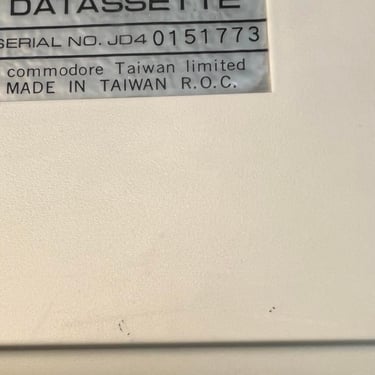
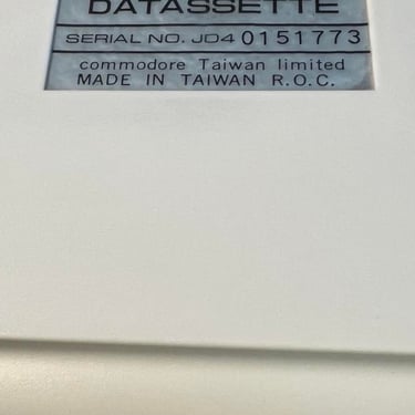
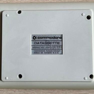
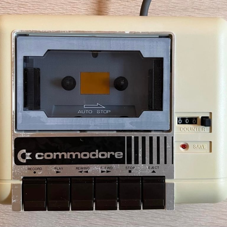
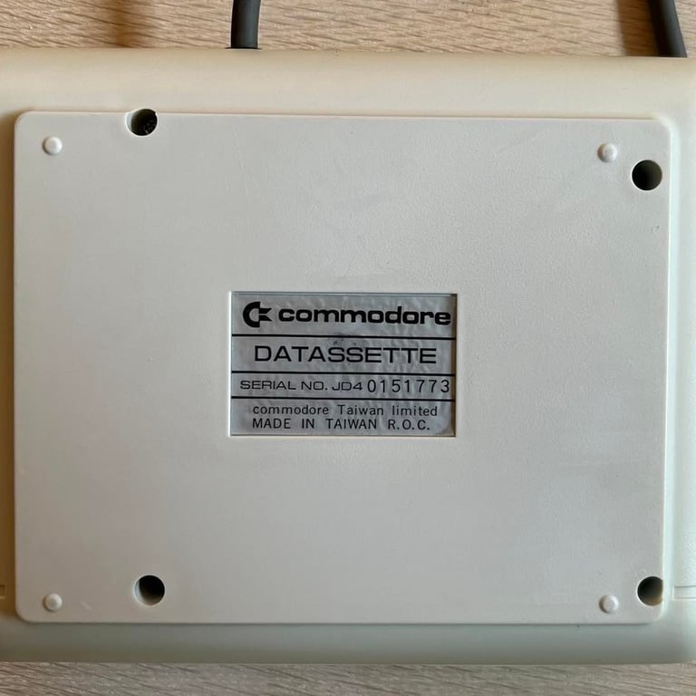
1530 (C2N)
Ser. No. 0151773
To refurbish this datasette the plan is to do this trough the following steps:
- Clean and remove stains from chassis
- Clean the interior mechanics
- Replace motor- and counter belts
- Check PCB for corrosion and replace old electrolytic capacitors
- Adjust head for optimal tape reading
- Verify datasette operation by testing
Refurbishment plan
Chassis
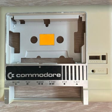
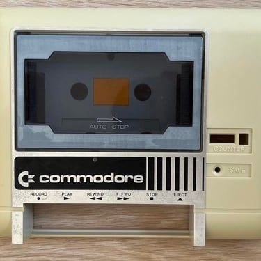
I began this refurbishment before my website was operational, so I don´t have any "before" pictures unfortunately. Nevertheless, I remember the visual state of this datasette to be quite ok. It was a bit dirty - but otherwise looking quite ok. The lid is missing the metallic finish, but I don´t think it matters much.
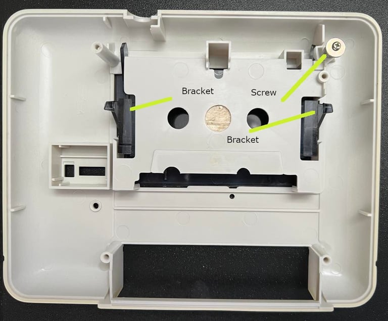
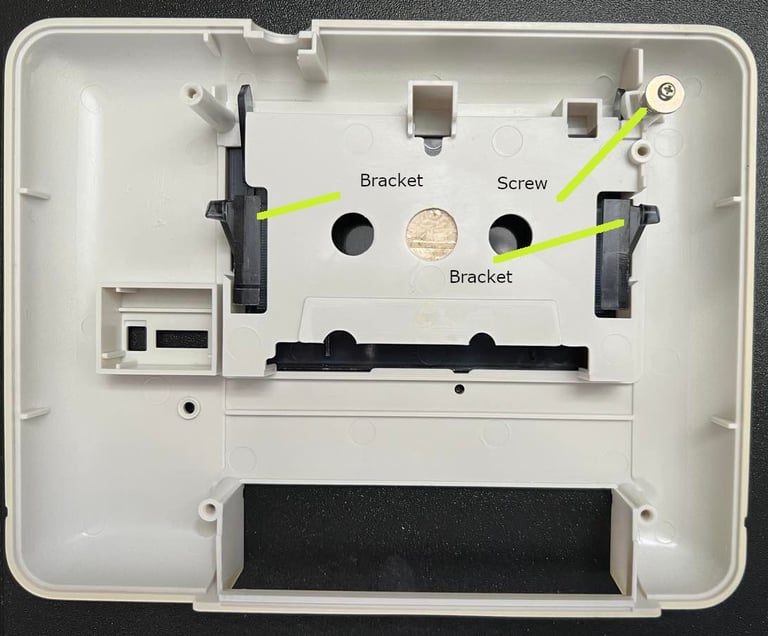
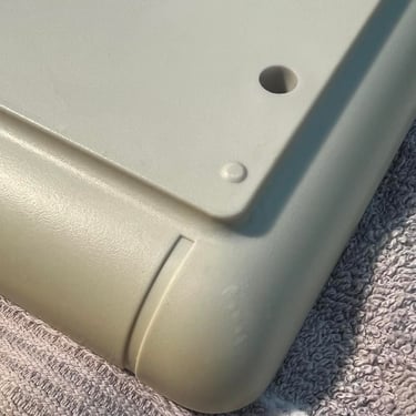
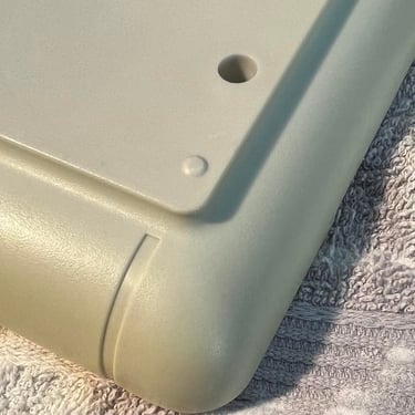
The datasette is disassembled by removing the four screws at the bottom cover. Also the lid is carefully removed - when I remove the lid I remove the screw in the upper right corner and gently push both brackets. This will loosen the lid from the top cover. See picture below for the positions of these.
When the lid is detached I carefully remove the yellow sticker inside the top cover. Sometimes this stickers are hard to remove and in such cases some heat (from a hair dryer) will help.
All parts are then washed with mild, luke warm, soap water. I use a paint brush to carefully wash all parts to avoid scratching the chassis. After this cleaning the chassis looks quite ok I think. Nevertheless, there are quite a lot of small marks which I remove with baking soda and glass cleaning spray. This is quite time consuming, but I think the result is quite good! See pictures below for some "before" and "after" pictures from this process - click to enlarge.
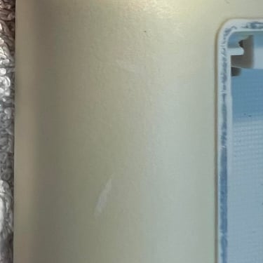
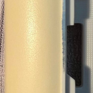
The final result of the cleaning looks quite nice I think. The datasette is a bit yellow (but not too much I think), the sticker at the back is a bit rugged and some of the metallic finish is gone - but all-in-all I think the result is good. See pictures below (click to enlarge).
Interior mechanics
The interior of the datasette is cleaned thoroughly. I do this by using a combination of compressed air, mild soap water, isopropanol, P240 sanding paper and vinegar. The compressed air removes most of the loose dust - especially in places where it is hard to reach with a Q-tip.
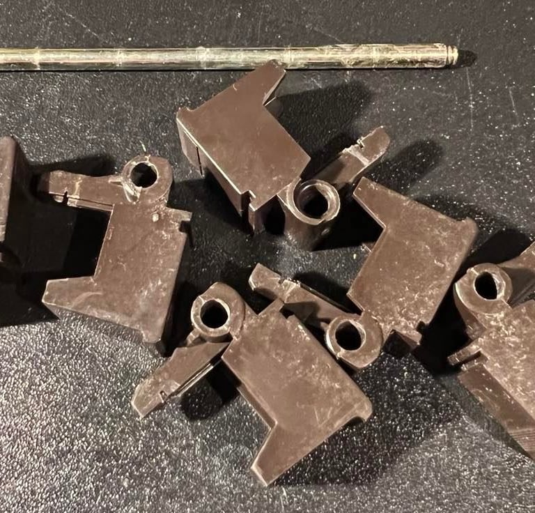
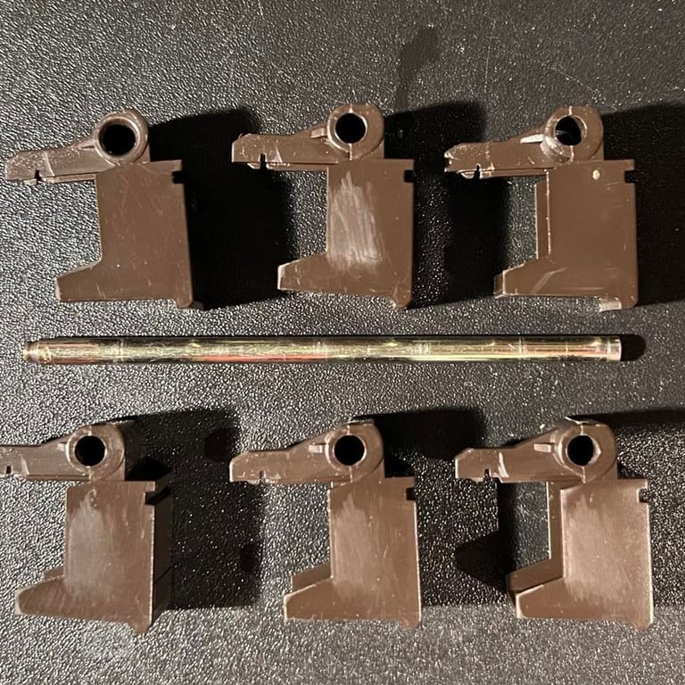
I remove all the keys also. This is easy to do by removing the little clip on the right hand side of the keys, and then gently drag the shaft out. Then every key kan be withdrawn from the interior. Note: there are three springs (Y-shaped) on the back pushing these keys. With the keys removed it´s likely that these will fall out so I put these in a plastic bag not to loose them.
Below you will find pictures, before and after, from the cleaning of the keys. Click to enlarge.
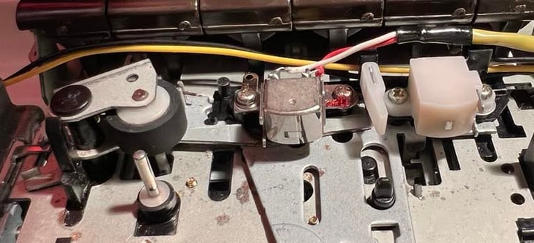
Four areas are cleaned with special care (see picture below for the position of these):
1) The erase head
2) The read/write head
3) The capstan and pinch roller
4) Rust below the keys

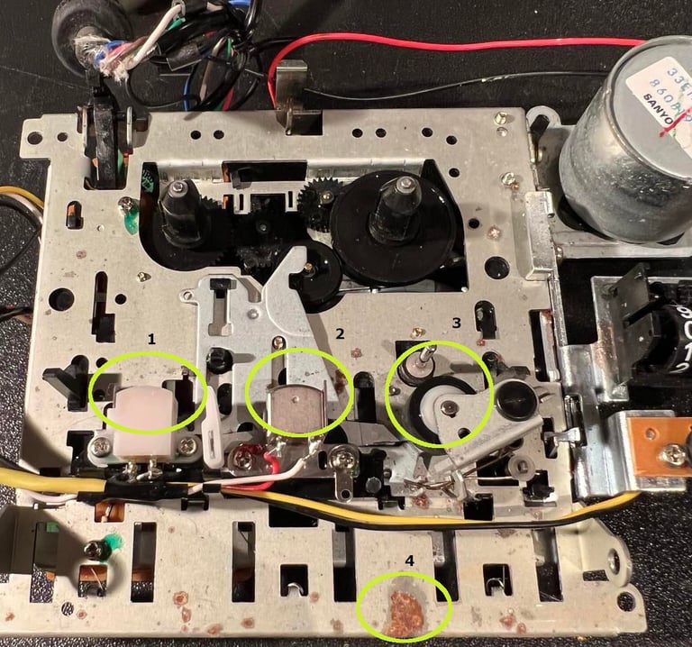
The erase- and the read/write head (area "1" and "2") are cleaned with isopropanol on a Q-tip. These are not very dirty, but it´s good to clean them anyhow. There are some areas with rust (or some mild corrosion). I use a Q-tip dipped with vinegar to remove this - the area marked "4" needs a good scrub with vinegar. It´s not possible (or more adequate: required) to remove all this corrosion from all spots. They are just some surface corrosion that does not affect any functions of the datasette. See picture below for the result of the removal of surface corrosion.
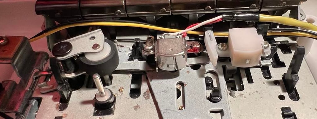
To clean the capstan and the pinch roller I do this in two stages. First I gently clean the capstan with isopropanol. The pinch roller I clean with a tiny bit of isopropanol and gently rub the pinch roller with some P240 sandpaper. The purpose of this mild sanding is to remove residue from tapes that are stuck on the rubber wheel.
The second stage of cleaning is done after the new motor- and counter belts are installed. The reason for this is that it´s now quite elegant to get an extra good clean of the capstan and the pinch roller - while they are moving! I connect the datasette to my C64 and press "PLAY". This will engage the capstan and the pinch roller, and while they are rotating I use a Q-tip with some mild soap water. Note that I place the Q-tip at the right hand side of the pinch roller to avoid the fabric getting stuck. See picture below (click to enlarge) to see the cleaned erase head, R/W head, capstan and pinch roller.
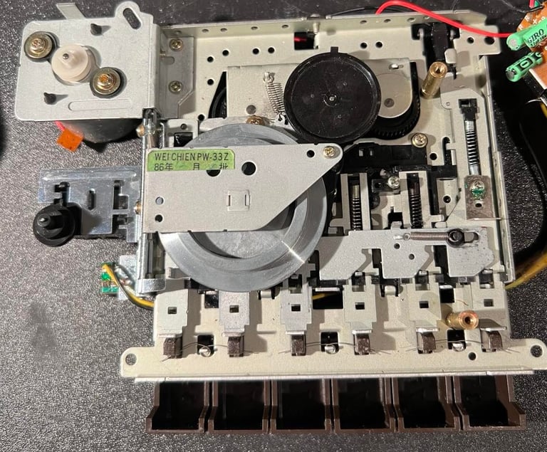
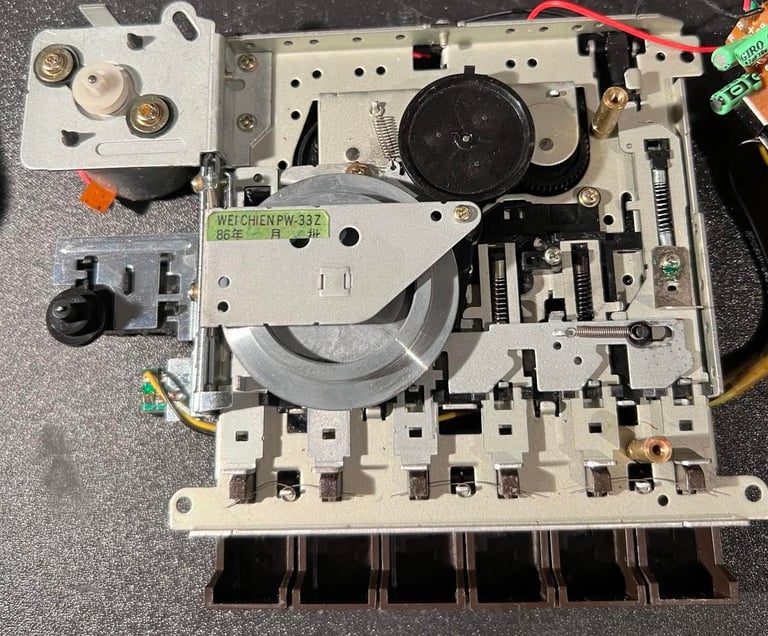
The backside of the interior is also cleaned. There is not very much to clean here actually since this side looks quite good already. Nevertheless, I clean everything with some mild luke warm soap water and isopropanol. Note that I also clean the "notch/channel" in the flywheel where the motor belt will be. The backside is cleaned while the motor- and counter belts are removed. See picture below.
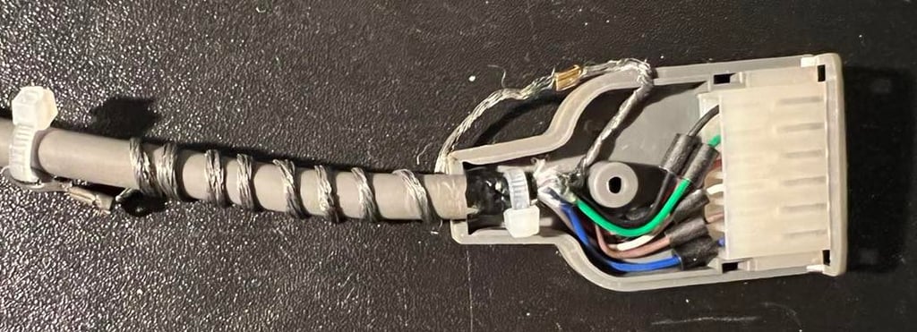
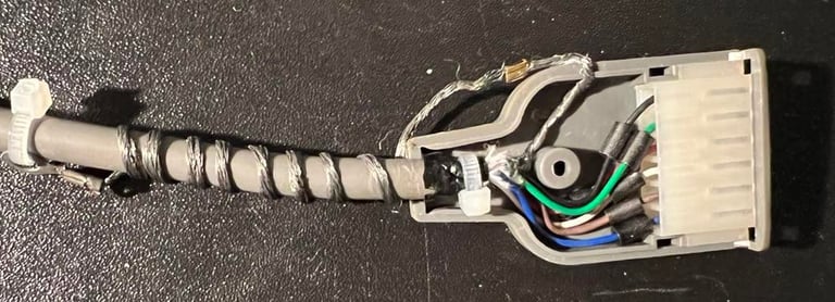
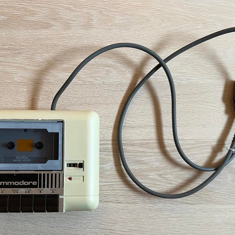
The cable is also inspected and cleaned with contact cleaner. I can´t see anything wrong with the cable, but I use a small cable tie inside the plastic cage. See picture below. This is to function as a strain relief to make sure that the cable is not pulled out of the plastic cage. Also, the ground cable is wrapped around the cable and tightened with a cable tie. You don´t want this cable to short circuit something in the user port - so I do this to get it out of the way. The ground cable is not used in the Commodore 64 (it was used in Commodore machines prior to the 64).
Motor- and counter belts
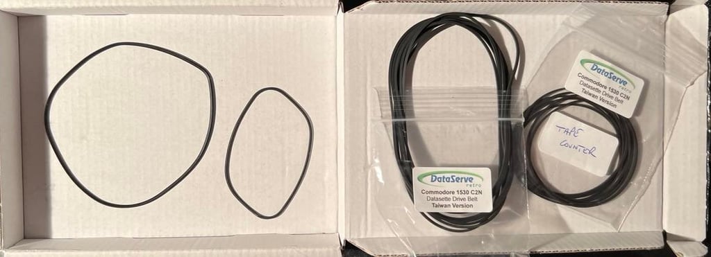
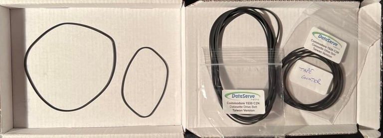
Both the motor- and the counter belts are removed and replaced with new ones. The new ones have been ordered from dataserve-retro.co.uk. Note that there are two main categories for belt sizes; one for "Made in Taiwan" datasettes and one for "Made in Japan" datasettes. This is a Taiwan version to I make sure to use the correct size... In the picture below you find the old belts to the left, and the new one to the right. Note that you can actually see the contour of the old belt positioning - after years stored away the position is "locked" in the belts.
The replacement of the counter belt is very easy. No screws need to be removed. It´s not mandatory to replace this belt as the datasette will work good enough without it, but I think it´s a good thing to replace them both. They are nearly 40 years old.
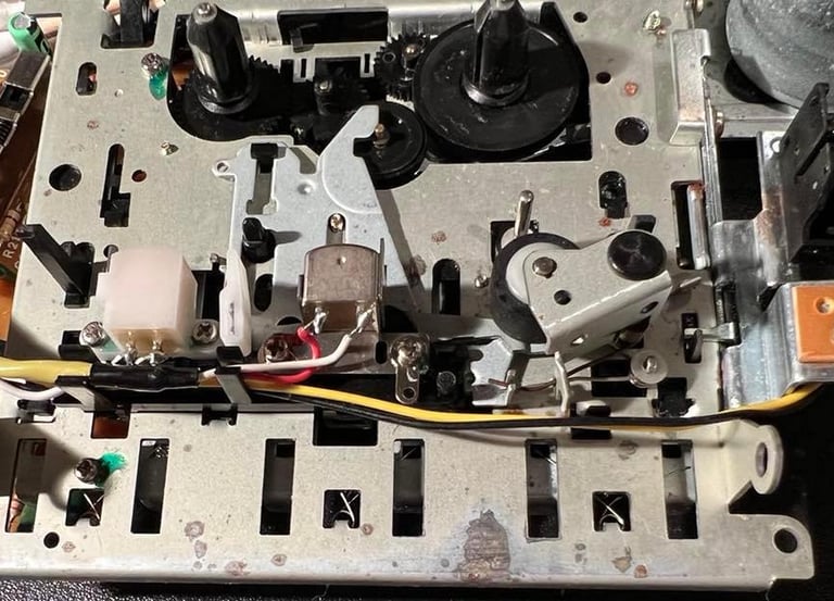
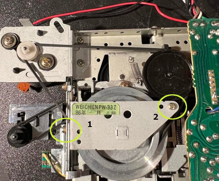
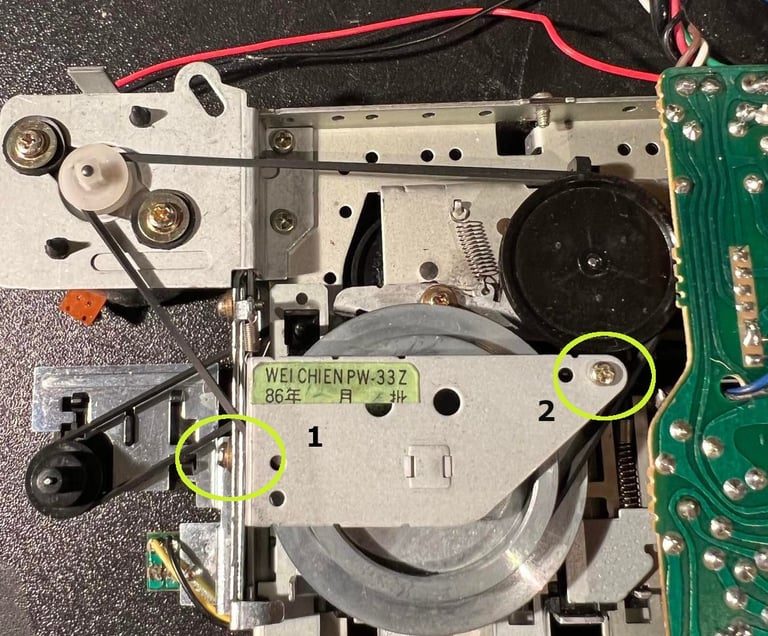
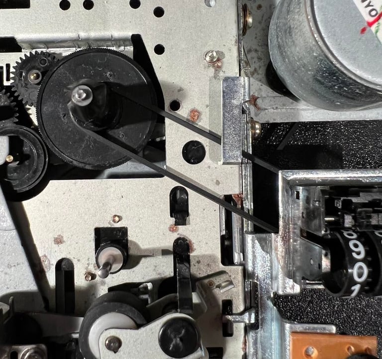
To change the motor belt I need to completely remove one screw (position "1") and partially remove one screw (position "2"). You only need to partially lift the plate above the flywheel - only enough to get the belt out. See picture below.

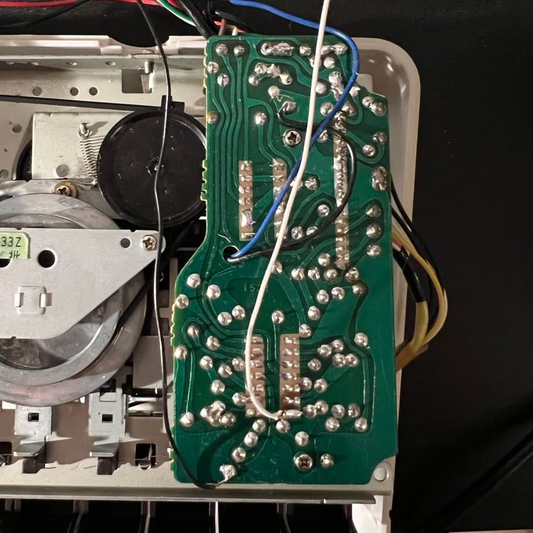
PCB cleaning and re-cap
There are only three electrolytic capacitors in this datasette: 3 x 47uF 16V. Since electrolytic capacitors can dry out it´s good to replace, and also to check for any corrosion or faults at the PCB. As far as I can see there are no issues with the PCB, so I only clean it with isopropanol and replace the old capacitors. I use 47uF 16 V capacitors from Wurth Electronics (bought at no.mouser.com).
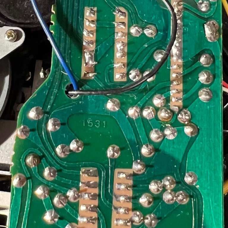
You will find pictures of the cleaned PCB (both back and front) with the new electrolytic capacitors below. Click to enlarge and see the pictures in full screen. This is the "1531" revision of the PCB.
Read/write head alignment
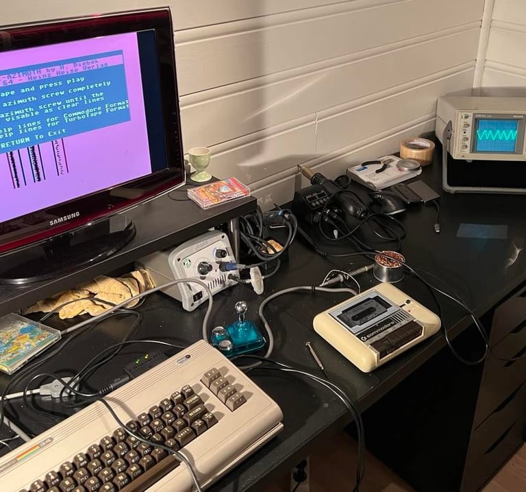
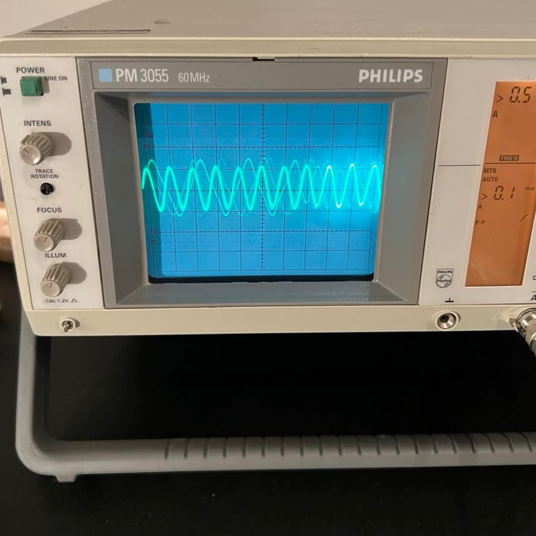
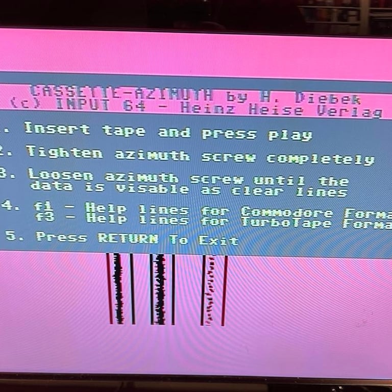
I´ve found that the easiest way to align the R/W head is to use both an oscilloscope and the azimuth align software on my C64 simultaneously, and then adjust the R/W head alignment screw.

To get a good measurement with the oscilloscope I solder on two wires on the PCB. These wires are then placed in parallell with the datasette cord and made available to the scope through the cable hole at the back side of the datasette. This method gives two advantages:
1) I can adjust the R/W head while the datasette is fully assembled. That means that the tape is in the correct position.
2) I can measure the output signal at the 2nd op-amp stage. This gives a DC signal which I think is way better to use as a reference while adjusting for optimal performance.
I mentioned earlier that this is the "1531" revision of the PCB. I found a very interesting page at World of Jani where he shows the op-amp schematics of the datasette. And also pictures where the different stages are at different PCB revisions. I use this page to find pin 7 (output stage 2) and ground. For a reference please check out his webpage here: http://blog.worldofjani.com/?p=1477.
See pictures below for where the two wires are soldered on, and how these two cables come out at the backside connecting the oscilloscope. Click to enlarge.
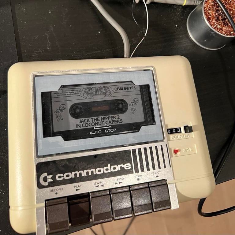
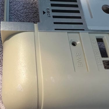
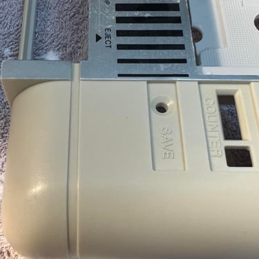
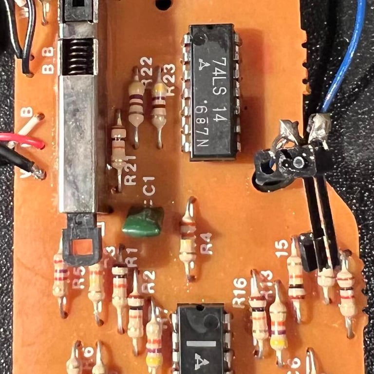
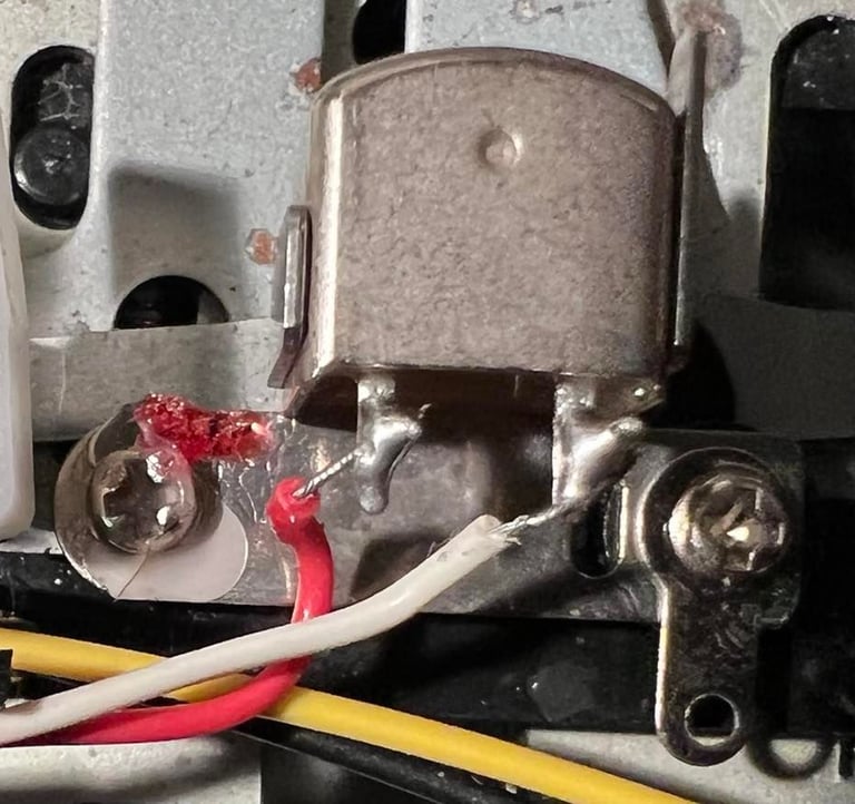
With a thin screwdriver I carefully adjust the R/W head through the small hole just above the second "O" in the Commodore logo. I watch the oscilloscope while turning - and when I reach the maximum amplitude I stop. And then at the same time verify the result with the azimuth software on my C64 -> three distinct lines telling me that the R/W is now aligned. See pictures below.
To secure the position of the R/W head I add a small drop of nail polish on the screw.

Testing
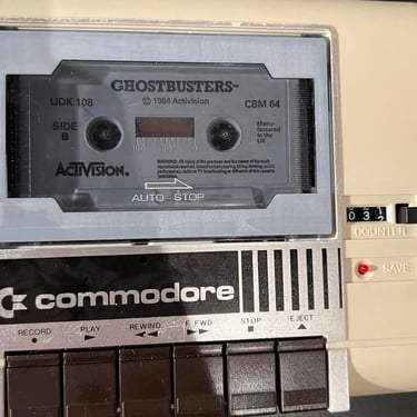
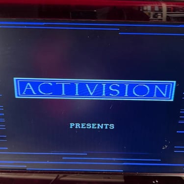
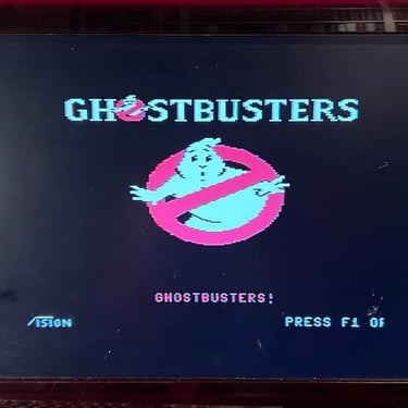
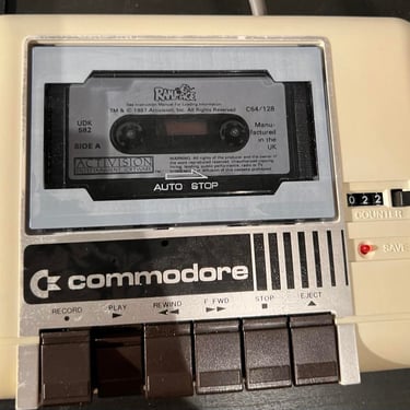
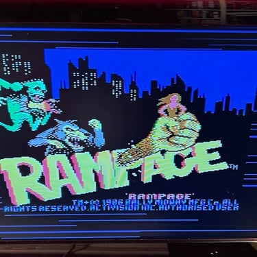
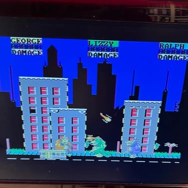
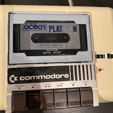
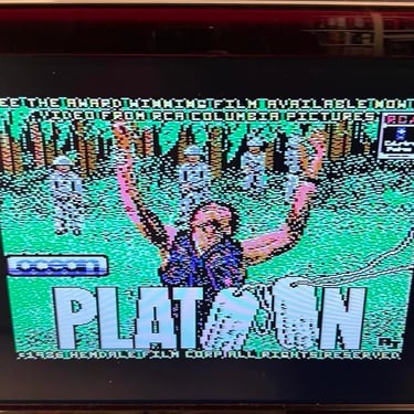
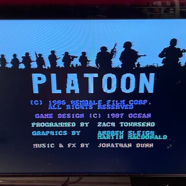
I pick three original old games at random for testing; Rampage, Ghostbusters and Platoon.


Result is that these three games loads ok. Well, Ghostbusters needs to be played at side B - but I think this tape is marginal. Anyway, as far as I can tell this datasette is working. Pictures below from the testing.
Final result
"A picture worth a thousand words"
Below is a collection of the final result from the refurbishment of this datasette.
Hope you like it! Click to enlarge!
Banner picture credits: Evan-Amos