

HOWTO
Datasette head alignment
Introduction
To make sure that the datasette can read and write cassette tapes without errors it is crucial that the tape R/W head is aligned correctly. This is often called “azimuth head alignment”. The goal of the datasette head alignment is to have a tape R/W head that is aligned so that it gives the best possible analog signal when playing and recording cassette tapes.
In this HOWTO article I will describe how I do this. I do not claim to be an expert on this, but hopefully you will find it useful if you plan to adjust your own datasette.
Standing on the shoulders of giants: my knowledge on this subject is a combination of gathering tips from the many skilled Commodore enthusiast and my own experience.
Background theory

The principle behind the datasette playback is that the analog signal from the tape R/W head is amplified and converted to a digital signal before being transmitted to the Commodore 64/128.
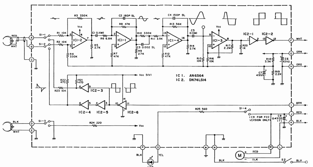
In the schematics below this principle is described. Please note that this schematics is for the “NP-090” assy of the datasette, but the principle applies for all versions.
The analog signal is generated from the R/W head seen at the left side of the schematics above. This signal is then amplified trough a chain of four operational amplifiers (OP-Amp). Now, the clever thing with this OP-Amp chain is that the signal will both be amplified, but also become converted to a semi-digital signal.
What happens is that for each of the OP-Amp stages the signal is continuously amplified. But when it reaches a certain amplitude, the amplitude is “cut-off” (saturated). In the schematics above this saturation barely starts to happen at the third OP-Amp stage. And at the fourth OP-Amp stage you can see that the peaks of the analog signal is "cut-off" (saturated).
After the fourth OP-Amp stage the semi-digital signal is input to two Schmitt triggers. The purpose of these Schmitt triggers is to create a full purpose digital signal out of the semi-digital signal.
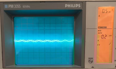
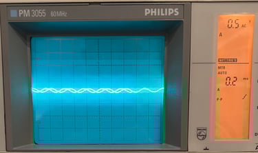
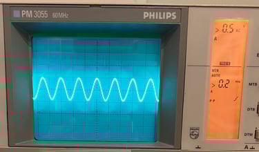
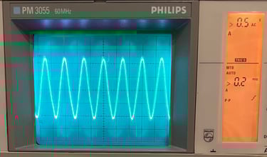
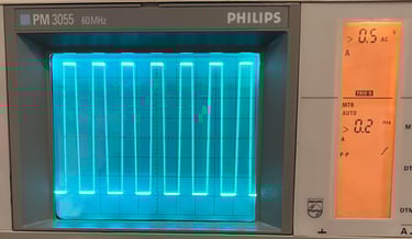
In the pictures below it is shown how a 3150 Hz sine signal from a audio calibration tape looks at each of the four stages (0.5 V/DIV). As can be seen the first three stages the sine signal amplitude increases by each stage until the fourth stage where the signal amplification is saturated resulting in a square wave.


Conceptual model - Aligning the R/W head
The conceptual model behind the alignment process:
Measure the analog signal from the output from one of the OP-Amp´s in the amplifying chain. The measuring point must be where the analog signal is amplified, but not saturated
While an original tape is running in the datasette - and the oscilloscope is connected at the OP-Amp output - the little screw at the left side of the read/write head is turned until maximum amplitude is reached
Verify that the read/write head is correctly aligned by using a Commodore 64 running properly cassette azimuth software
Lock screw in position with some tightening material
Measuring the signal - where?
Where to measure the analog signal in the OP-Amp chain? It needs to be amplified, but not saturated. My experience is that the 2nd OP-Amp is the best place to measure. At this stage the signal is amplified enough to clearly see how the amplitude changes from maximum to minimum while adjusting the screw on the R/W head. This "spot" is based on the great article on how to make a VU-datasette from World of Jani.
Now, to actually measure the signal on the oscilloscope during playback two wires needs to be soldered onto the PCB; one wire from the 2nd OP-Amp output and one wire to ground. These two wires need to long enough so that they can be brought out of the datasette alongside the cable connected to the Commodore 64.
Important: to get a proper adjustment of the R/W head the datasette must be completely re-assembled with screws and everything. If you adjust the R/W head without the top- and bottom cover in place you risk that the R/W will be "wrong" aligned since the covers can place the cassette in a different position. The two wires which are soldered to PCB will be connected to the scope, and with a completely assembled datasette the R/W is aligned by finding the maximum amplitude on the scope.
Where to find the places to solder the two wires?
Well, it depends on the PCB assy. All datasettes have four OP-Amps in amplifier chain, but some PCBs have two separate OP-Amp chips (2 x 2) and some have only one OP-Amp chip (1 x 4).
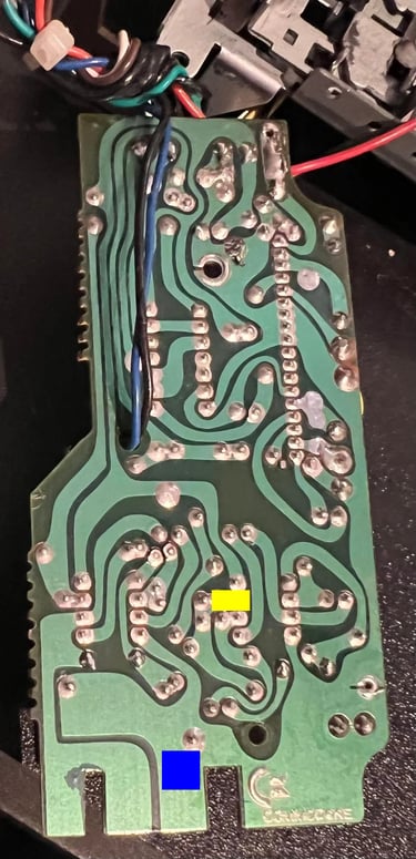
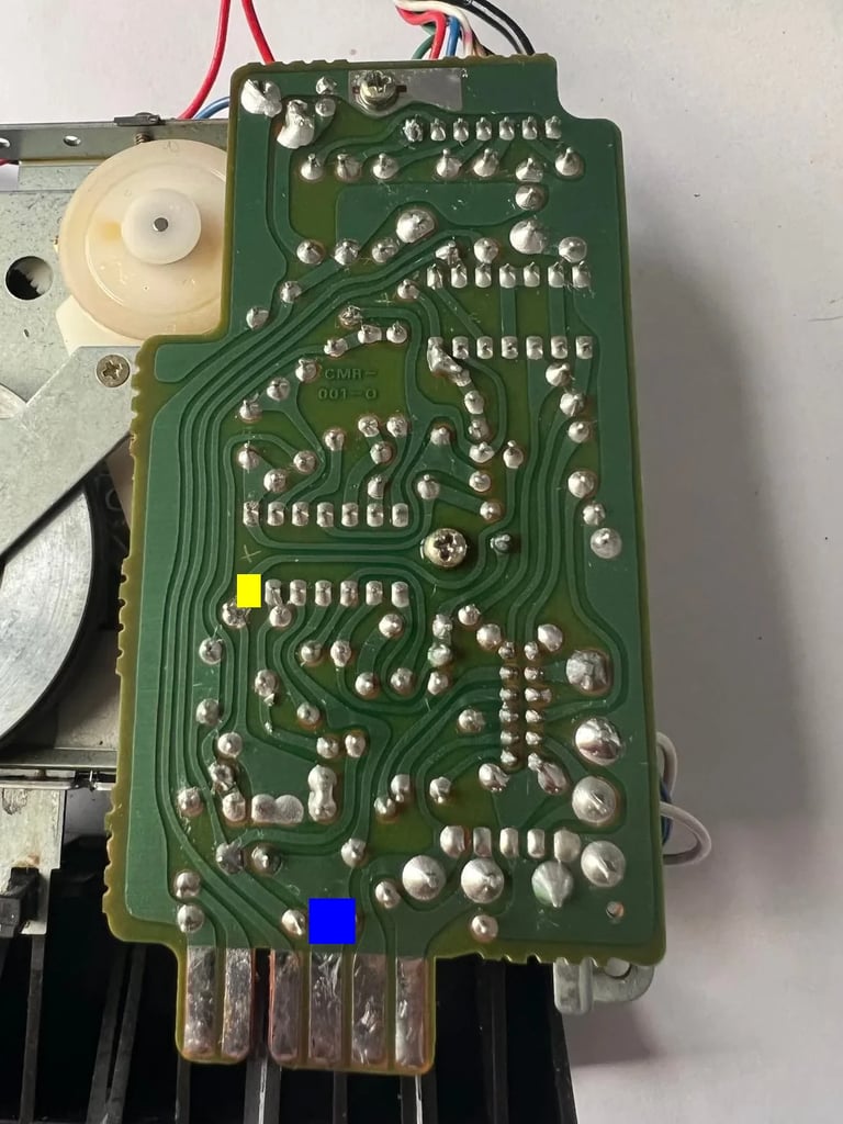
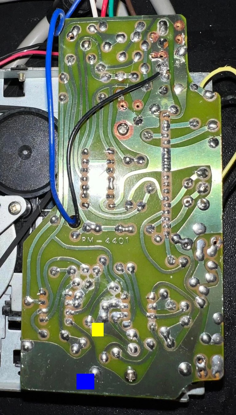
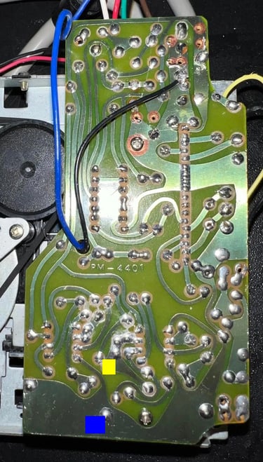
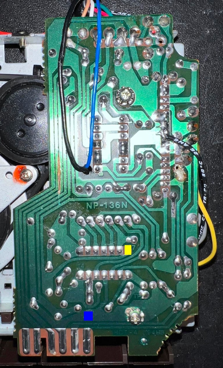
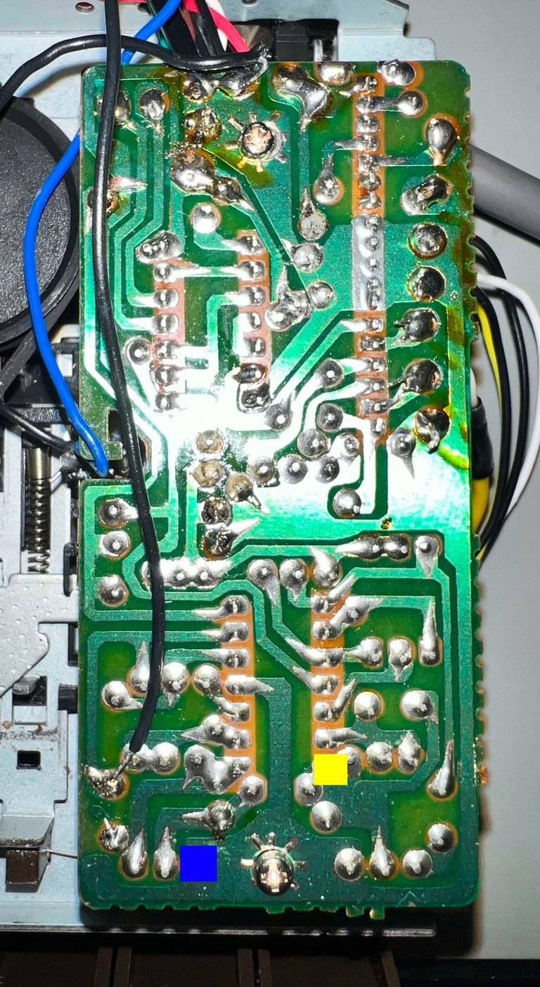
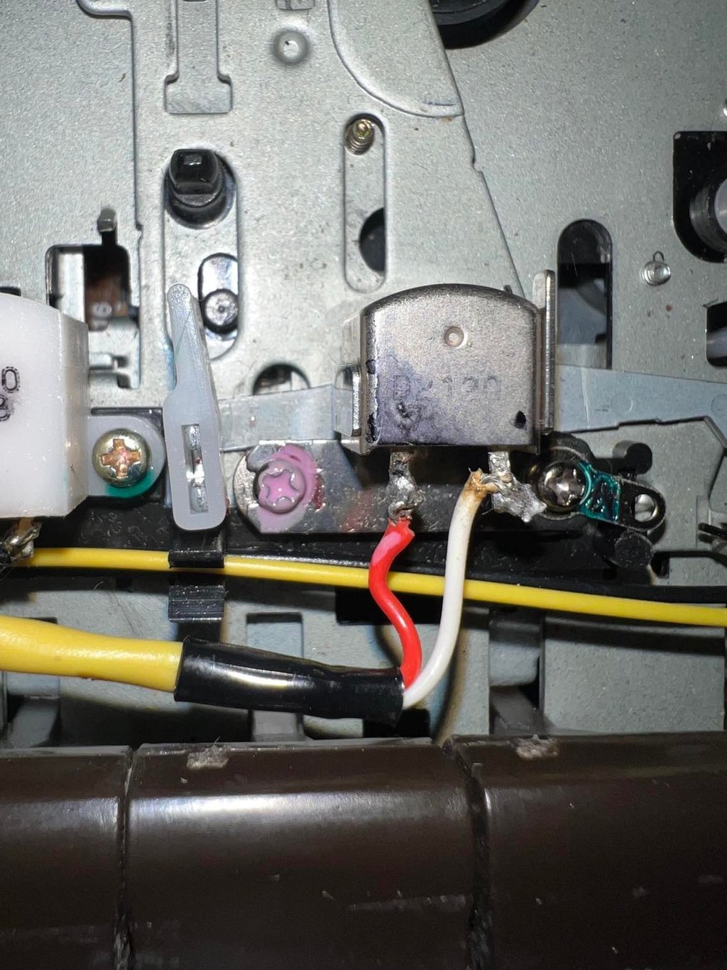
Below are some pictures of where these two points can be found on the datasettes I´ve refurbished so far. The yellow square indicates where the first wire must be soldered (output signal from OP-Amp), and the blue indicates where the second wire must be soldered (ground).
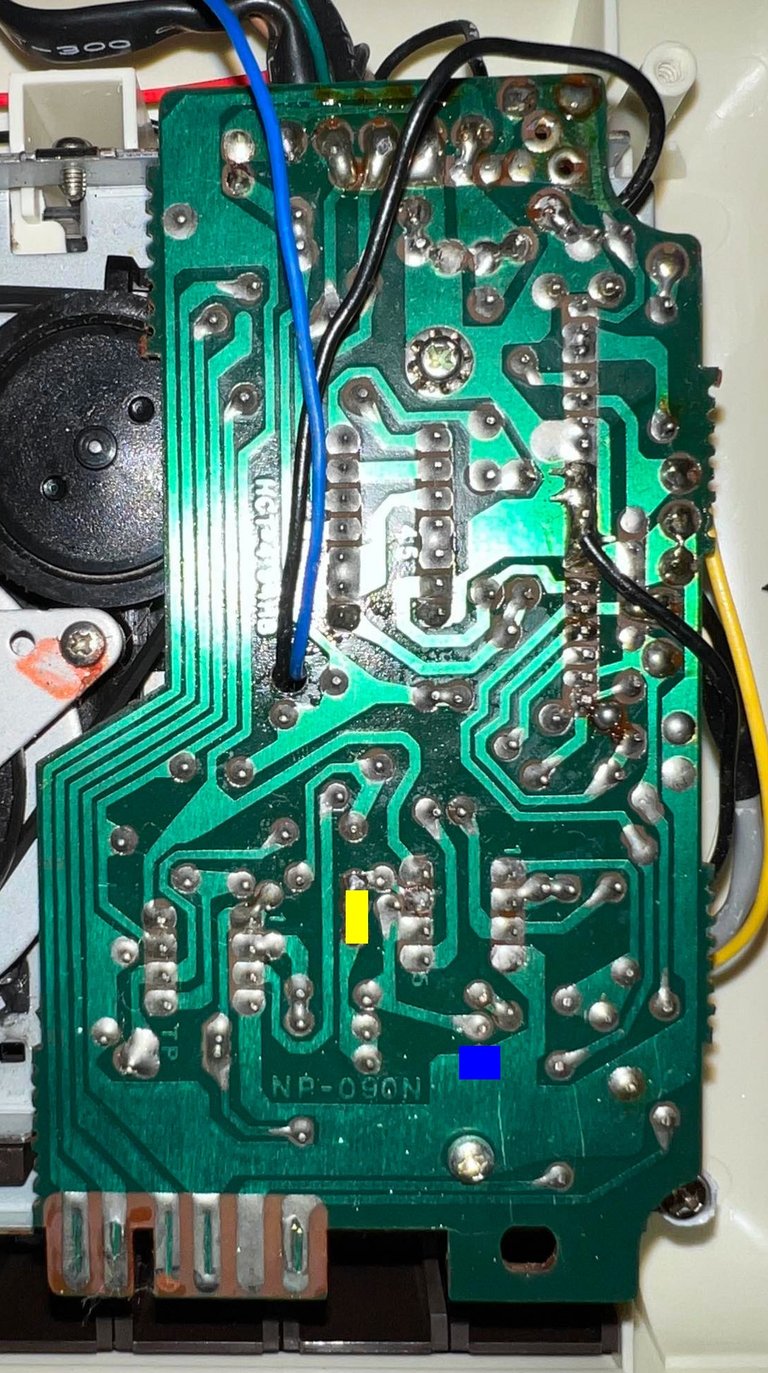
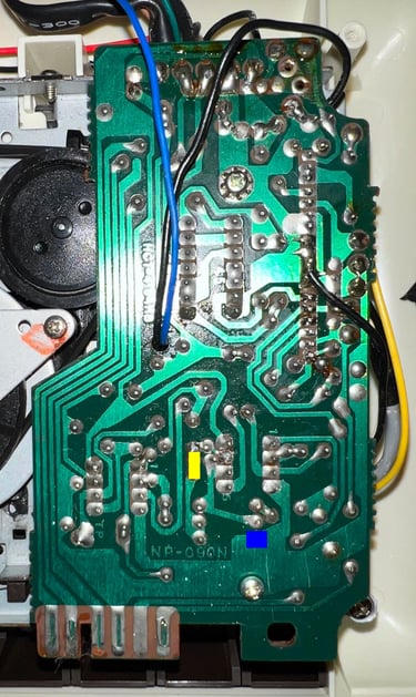
NP-090N
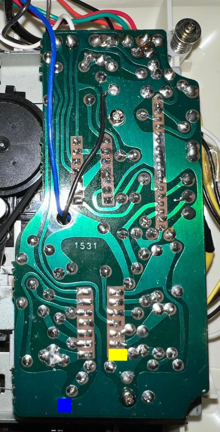

1531
CPC-47 94HB (1530)

CMR-001-0
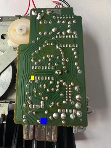
PM-4401 (Fujisonic)
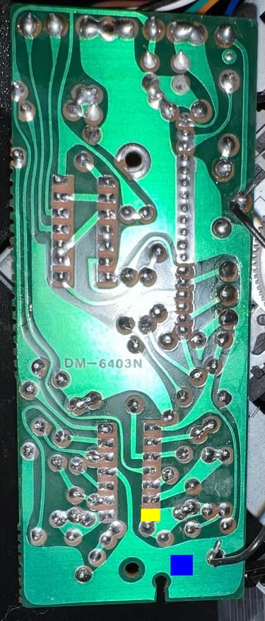
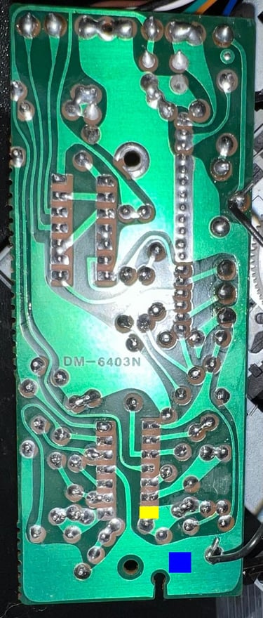
DM-6403N (Datenrekoder)
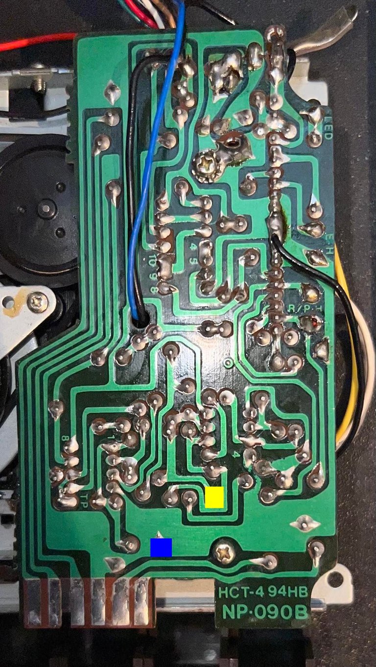

NP-090B
NP-136N

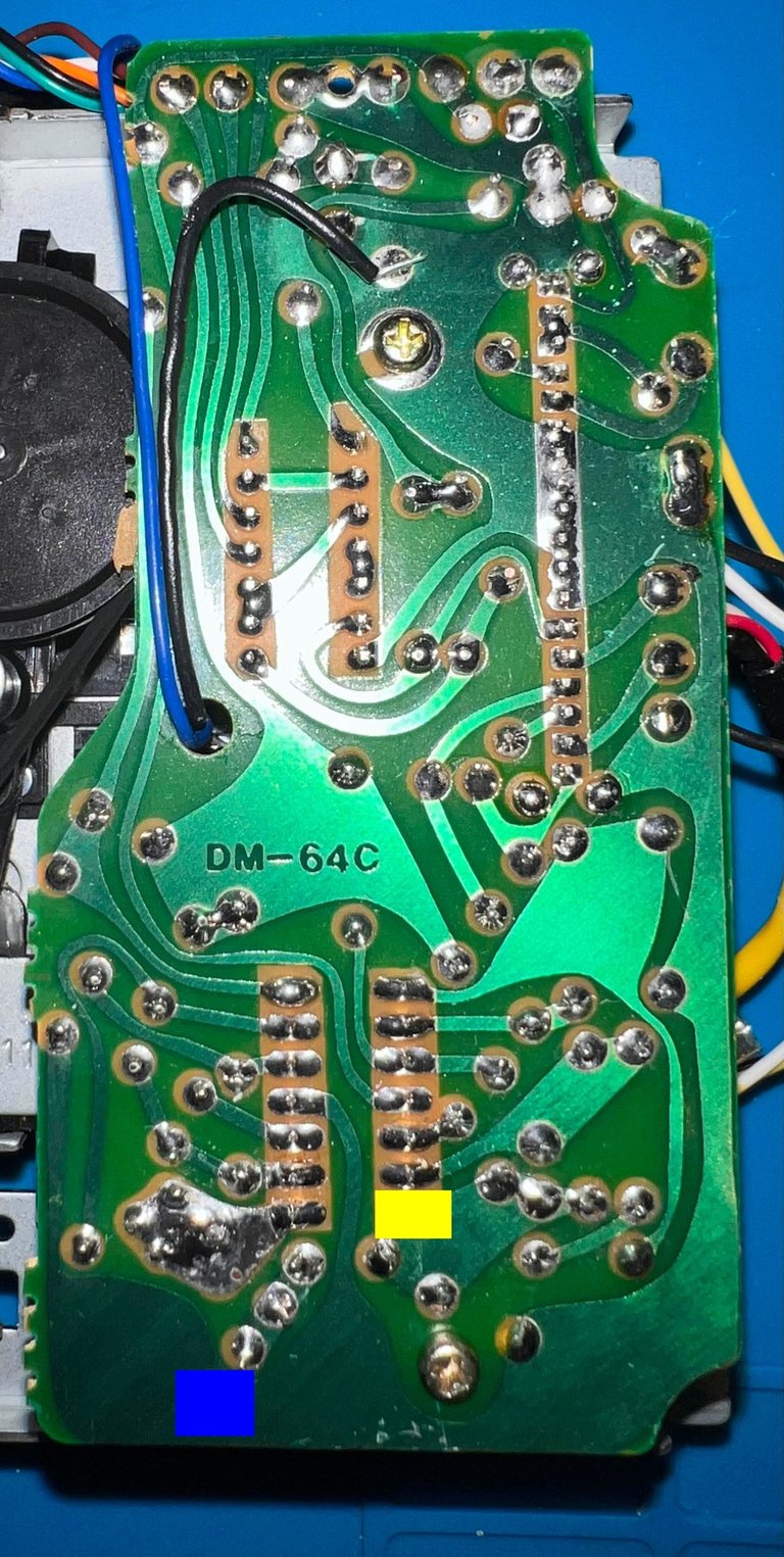

DM-64C (Datenrekoder)

Measuring the signal - what should it look like?
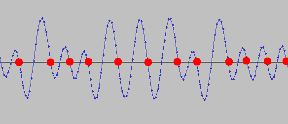
The Commodore compatible datasette use Frequency-shift keying to encode the data. This means in simple terms that a "0" and "1" are encoded by using two different frequencies. The picture below shows a typical waveform from the datasette (source: How Commodore tapes work)
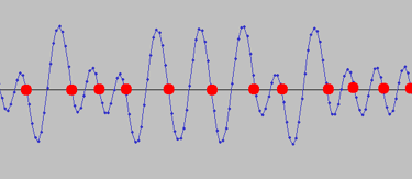
You can read the details on how the encoding is done in the source link above. But think of the encoding like this; a "0" is a short and low amplitude pulse and a "1" is a long and high amplitude pulse. So in the picture above the signal will be : 010011101000.
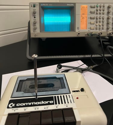
When watching on an old analog oscilloscope (which I have) you will see the signal dancing around and will typically look like the picture below. It is worth noticing that the amplitude on the "0" and the "1" are different as seen in the picture above. And while watching the signal on the oscilloscope you will see this effect quite good - it is not a nice stable sinewave with a fixed amplitude.
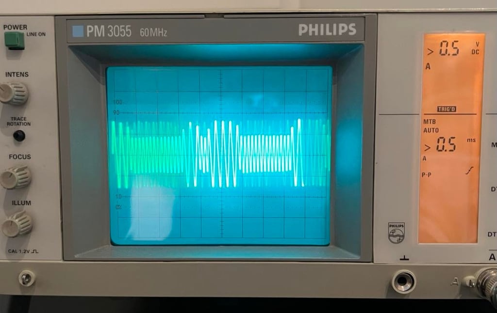
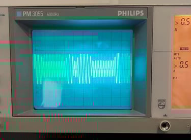
So what is the maximum signal strength we can get? My experience is the maximum amplitude for the "1" signal is about 0.8 V at the 2nd OP-Amp stage. This will give a peak-to-peak value of 1.6 V. In the picture above the oscilloscope is set to 0.5 V/DIV.
Adjusting the R/W head
The R/W head can be adjusted by turning the little screw which is on the left side of the head. See picture below - the blue circle shows the position of the alignment screw.
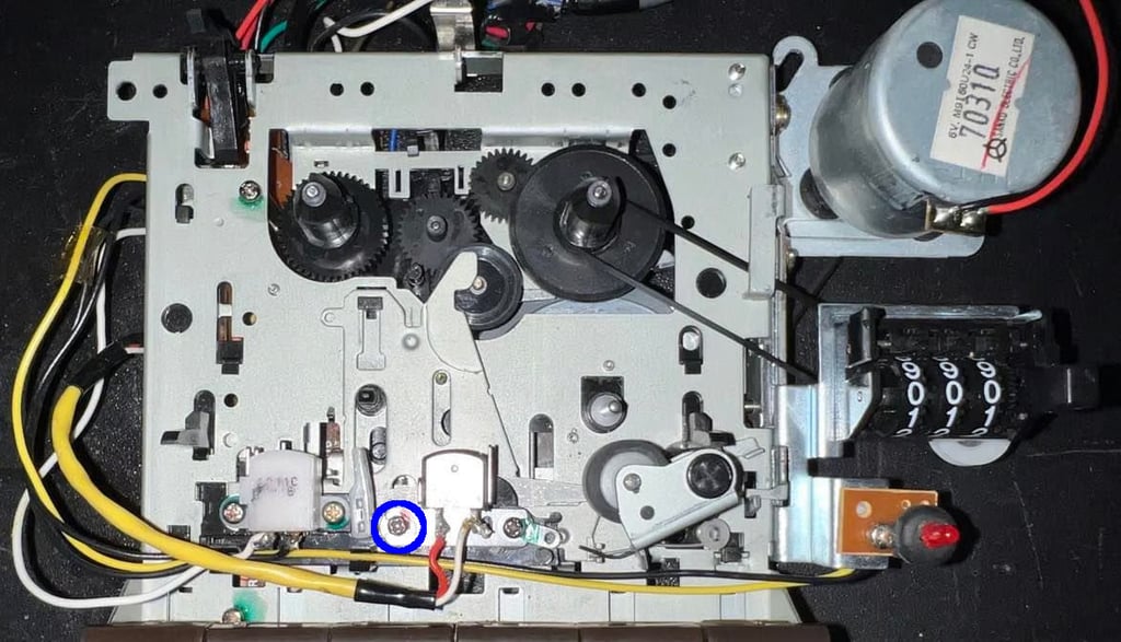

NOTE#1: it is very important that the alignment is done when the datasette is completely assembled. Otherwise you could experience that even if the R/W were aligned without the exterior chassis it will be somewhat misaligned when all the parts of the datasette is assembled. There is a small hole in front of the datasette which is designed for this purpose. When the datasette is set to "PLAY" the screw become available trough this little hole. As seen in the picture below a small screwdriver fits perfectly into this hole and you can adjust the R/W head while the datasette is assembled. You can also see the two wires soldered to the PCB coming out of the datasette and are connected to the oscilloscope.

To align the R/W head first tighten the screw completely (clockwise). Then start the tape while watching the signal appear on the scope. At first, the signal will be barely visible. Then start turning the screw counter-clockwise and the amplitude will start to increase. Keep turning until the signal reaches maximum and begin to decrease. Then turn the screw back to maximum - you should now have the optimal R/W head alignment.
NOTE#2: Make sure to use a original recorded tape (e.g. an original game for the Commodore 64). The reason for this is that these tapes have been recorded professionally. If you use own recorded tapes you are likely to align the R/W head wrong - it will be aligned to a special recording instead of a general professional recording.
In the video below you can see how a signal is increased from "zero" (screw tightened completely) to maximum.

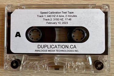
NOTE#3: I can sometimes be a bit hard to find the optimal amplitude of the signal since it is dancing and jumping all around. There is a way to circumvent this; by using "Speed Calibration Test Tapes" you will get a nice since wave of e.g. 440 Hz or 3150 Hz (picture below). Even if these tapes are designed for measuring the tape speed they also serve the purpose of giving a stable sine wave. With a stable sine wave it is easier to get a good calibration. In the video below the same calibration is done - but now with a "Speed Calibration Test Tape" loaded in the datasette.


Verification -
is the R/W head really aligned?
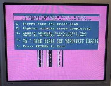
To make sure that the alignment operation was a success it is important to verify that it is indeed correctly aligned. To do this you can use the C64 Cassette-azimuth software.
Connect the datasette to the Commodore 64, start the cassette-azimuth software and press "PLAY". If the alignment was a success you should now see three vertical lines being drawn on the screen. These lines should have some scattering, but should appear as semi-solid lines. If the alignment is off these lines will be very scattered and barely looking like lines at all.
Picture below shows the cassette-azimuth software running after a successful R/W head alignment.

Last part of the verification is to play some original tapes on the datasette and the Commodore 64. Make sure that they are "known good working" tapes. They should now load successfully without any issues.
Closing - locking it all up
When everything is tested and verified it is time to "lock it all". This is done by carefully opening the datasette and desolder the two wires. Then put a drop of glue / tightening material on the alignment screw. I use nail polish for this operation.
When applying the glue/nail polish make sure you don´t spill it to other areas in the datasette. If you get glue in these places you risk that the mechanical operation will malfunction.
