

HOWTO
Checking the
Commodore 64 voltages
Introduction
For the Commodore 64 to operate flawlessly it is crucial that the voltages powering all the components on the mainboard are correct. They all need to be present and needs to within acceptable tolerances.
Voltages? As in plural? It is not sufficient just to check the 9V AC (1.0 A) and 5 V DC (1.5 A) from the PSU? In short; no. E.g. you will see in this article that here are more than just one 5 V DC and that both 9V DC and 12 V DC are required for the mainboard to operate.
In this HOWTO article I will describe how I check the voltages on a Commodore 64 primarily with a "longboard" mainboard. This mainboard has the MOS 656x VIC-II and the MOS 6581 SID chip. There are some voltage differences on the "shortboard" mainboards with the MOS 856x VIC-II and MOS 8580 SID chips, and I will try to describe these differences in the article as good as I can. I do not claim to be an expert on this, but hopefully you will find it useful if you plan to check that your Commodore have all the required voltages.
Standing on the shoulders of giants: my knowledge on this subject is a combination of gathering tips from the many skilled Commodore enthusiast and my own knowledge and experience.
Note:
Before doing the voltage measurements make sure that the power connector and switch are fully operational. Often it helps to spray contact cleaner in both the connector and switch, reconnect / connect the power plug several times and "massage" the switch to get the maximum voltage. After 30+ years these connector can be oxidised creating unwanted current resistance.
Background theory
C64 Power Supply (PSU) voltages
It all starts with the Commodore 64 power supply (PSU). The original PSU is Infamous for failing; if you are lucking it will just stop working and if you are unlucky it can cause havoc inside the machine destroying several precious MOS chips due to too high voltage.
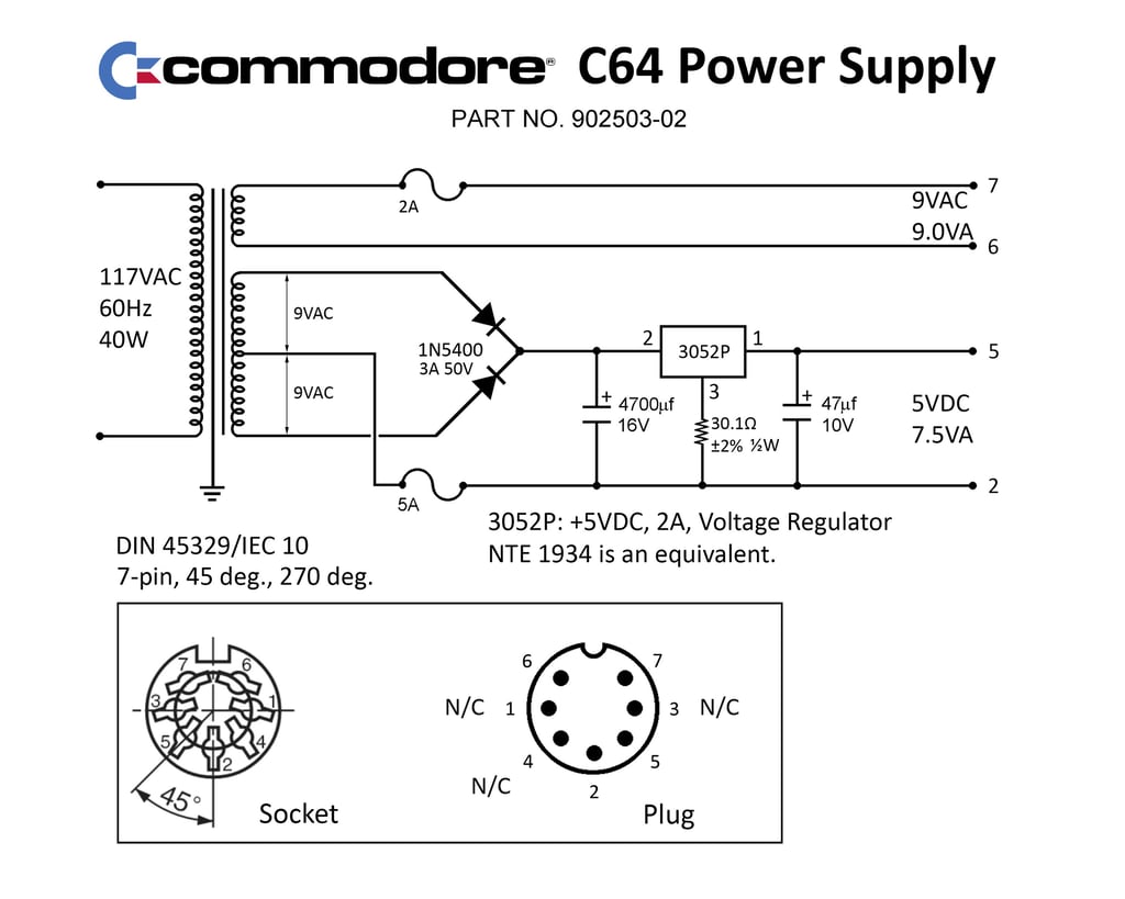
The PSU provides the Commodore 64 mainboard with two voltage sources: 9 V AC and regulated 5 V DC. The schematics and pinout for the Commodore 64 PSU (110 V version) is shown below (source).
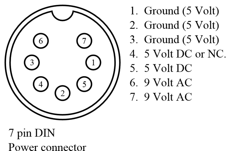
Note that there are some version of the PSU where pin #4 is used instead of pin #5 for 5V DC. Also pin #1 and pin #3 can be used as ground instead of pin #2. The image below show the pinout alternatives (seen from the plug).
C64 Mainboard voltages - Longboard edition(s)
There are six voltages that are of special interest on the Commodore 64 mainboard - longboard editions. All of these have different voltages, current flow and purpose within the machine - see table below.

WARNING: Before connecting an old original power supply to a Commodore 64 check the voltages. The 9 V AC doesn´t normally fail, but it is quite common that the 5 V DC is too high. I don´t think there is a hard limit on how high voltage the chips can handle, but if the voltage is higher than 5.25 V I would recommend NOT to use this.
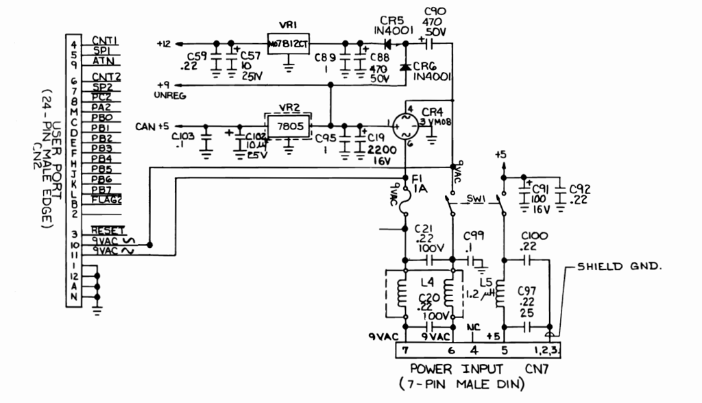
The schematics below shows how the power is supplied from the PSU trough the CN7 input connector on the mainboard and how this is used to generate a 12 V DC, another 5 V DC (called CAN 5) and an unregulated 9 V DC.

5 V DC - To power the CPU, PLA, CIA, ROM, RAM, SID (Vcc) and glue logic
All the chips, with the exception of VIC, on the mainboard are powered by this +5V DC. This includes the CPU, PLA, CIA, ROM, RAM, SID (Vcc) and glue logic. The 5V DC is derived directly from the power supply trough the CN7 plug and only filtered by L5, C97 and C100 before provided to all the chips.
Note that the SID chip is also powered by this +5 V DC rail. But the SID also has a second voltage source (Vdd) either of + 12 V DC (MOS 6581) or +9 V DC (MOS 8580). See information about +12 V DC generation later.
5 V DC - To power the VIC-II (Vcc) and clock circuits
The VIC-II chip and the surround clock circuitry is powered with a separate 5 V DC often called "CAN +5V". Why a separate 5 V DC? Well, I don´t really know but I guess it has something to do with noise from the other chips on the mainboard if they were on the same 5 V rail. Anyhow, the 5V DC is generated by first converting the 9 V AC to 9V DC (unregulated) through the CR4 bridge rectifier. Then this 9 V DC is converted to +5 V DC regulated through the 7805 voltage regulator.
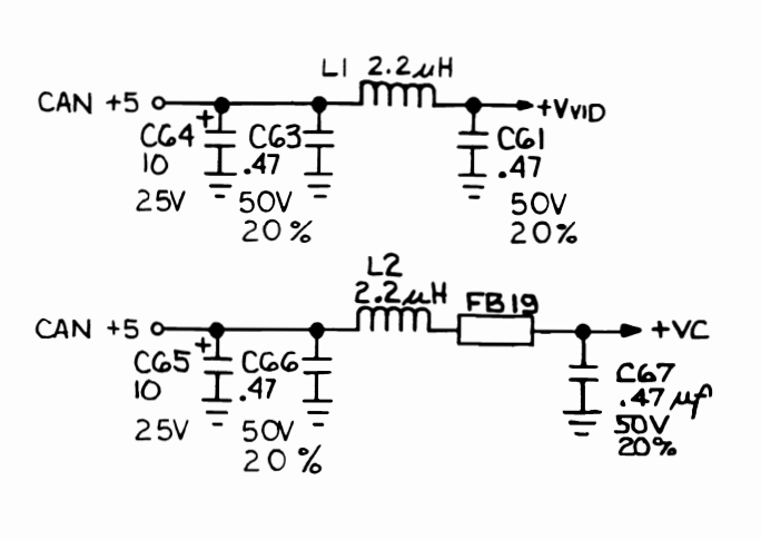
Further on, the regulated 5 V DC from the voltage regulator is filtered into two sources; one for the VIC-II and one for the surround clock circuit - both "(CAN)ned" inside the RF-shield. Schematics below show filters used to generate Vvid for the VIC-II and Vc for the clock circuits.
Note that the VIC-II chip also has a second voltage source - Vdd - (just like the SID). This second source has a voltage of either +12 V DC (MOS 656x) or +5V DC (MOS 856x). See information about +12 V DC generation later.

12 V DC - To power the VIC-II (Vdd), SID (Vdd) and audio amplifiers
The 12 V DC is output from the 7812 voltage regulator. The input of the voltage regulator is in the order of 2 x 9 V. This is because the + 9V DC (unregulated) is added to the 9 V AC, rectified through CR5, and then the total is input to the 7812 voltage regulator.
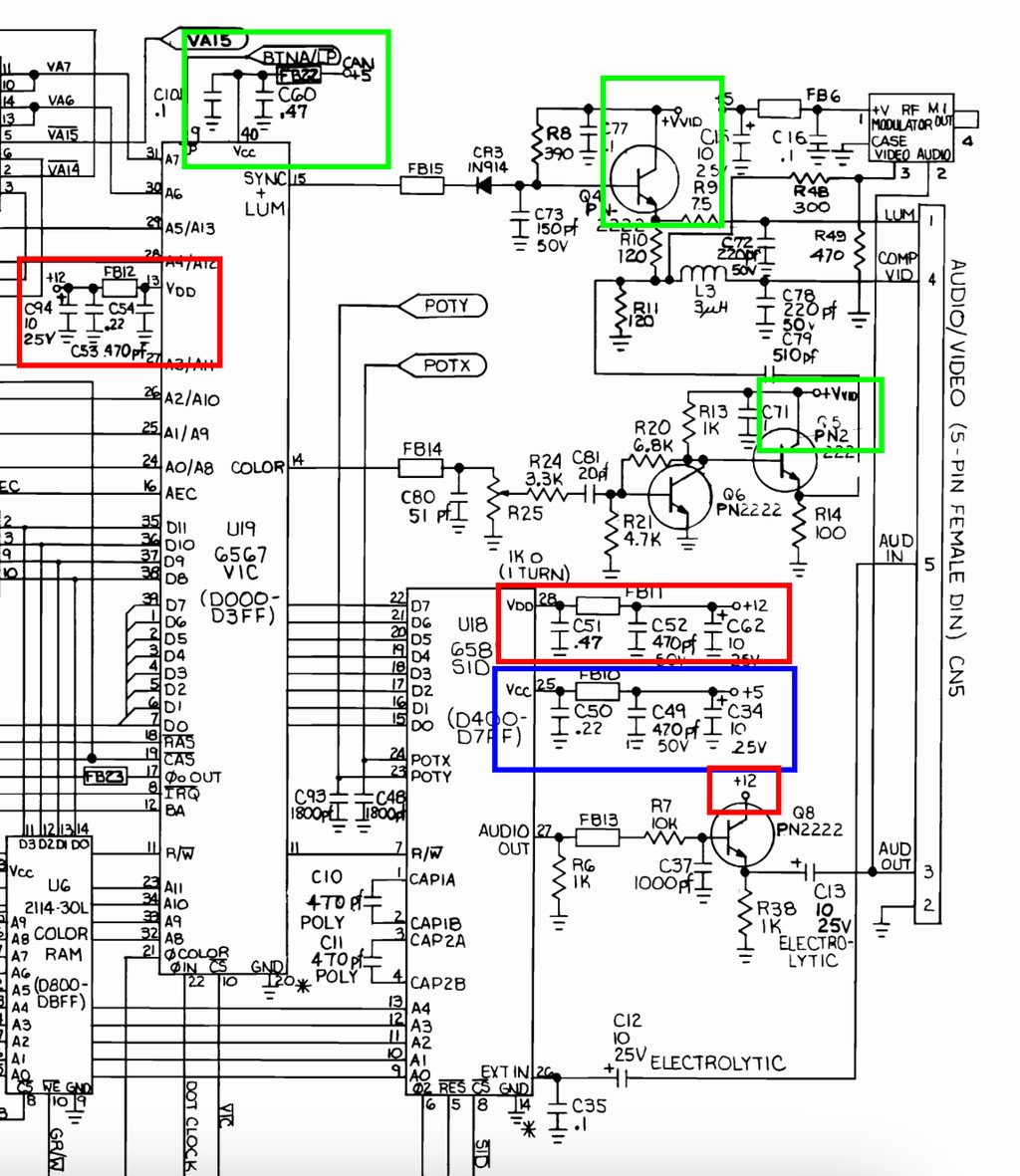
In the schematics below the voltages for the SID, VIC-II and the audio amplifier are shown. The blue area shows the +5 V DC (from PSU) to SID, the green area shows the +5V DC (CAN) to VIC-II and the red areas shows the +12 V DC to the SID, VIC-II and audio amplifier.
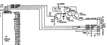
9 V unregulated DC - To power the datasette motor
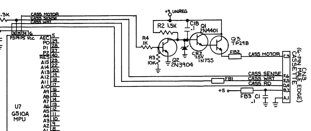
The 9 V unregulated DC is simply generated by rectifying the 9 V AC from the PSU through the CR6 diode. This supplies the transistor amplifier circuits in the datasette to power the motor. The "+9 UNREG" is shown in the schematics below - and shows how the +9 V unregulated DC is used to power the transistor circuits between the CPU and the 6-pin datasette port.
C64 Mainboard voltages - Shortboard edition(s)
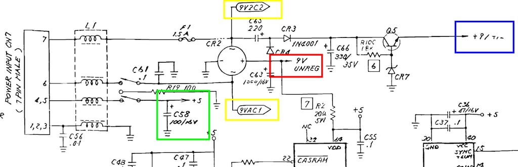
The biggest difference between the longboard and the shortboard, from a voltage perspective, is the lack of a +12 V DC and a CAN +5 V DC. These voltages which are supplied from the 7812 / 7805 voltage regulators on the longboard are not present at all on the shortboard. Instead, the + 12 V DC is replaced by a +9 V DC and the CAN +5 V DC is replaced by the normal +5 V DC from the power supply (PSU).
Schematics below shows the power circuitry for the shortboard. Blue: regulated +9 V DC, red: unregulated +9 V DC, yellow: 9 V AC and green: regulated +5 V DC.
Measuring the voltages - where?
C64 Mainboard voltages - Longboard edition(s)
#1: 5 V DC - From the PSU
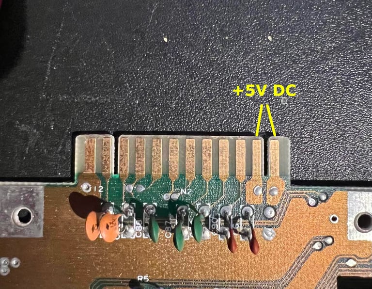
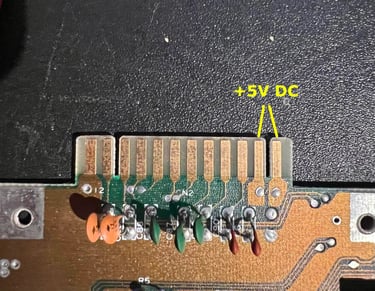
The easiest place to measure the 5 V DC which stems from the power supply (PSU) is at the user port. Pin #1 is ground (GND) and pin #2 is 5 V DC - the rightmost notch.
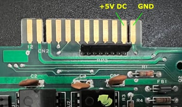
Also it is wise to check the +5 V DC supply on a few of the chips. In the table below is a list of suggested chips to check, and which pin to measure for + 5V DC.
#2: 9 V AC - From the PSU
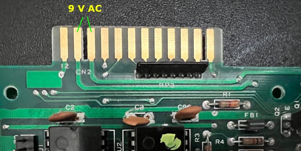
Just as easy as the +5 V DC the user port is a great place to check. The 9 V AC is found at pin #10 and #11 - the leftmost notch.

#3: CAN +5 V DC - Supply to the VIC-II (Vvid)
Best place to measure this voltage is at pin # 3 on the 7805 voltage regulator. As explained in the background theory chapter previously we know that this is not completely correct since the CAN +5 V DC is actually split in two; Vvid and Vc. But in my experience it is sufficient to measure directly on the 7805, and measure directly on the VIC-II if in doubt if the voltage supply reaches the chip.

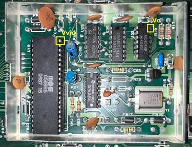
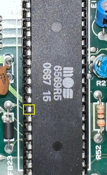
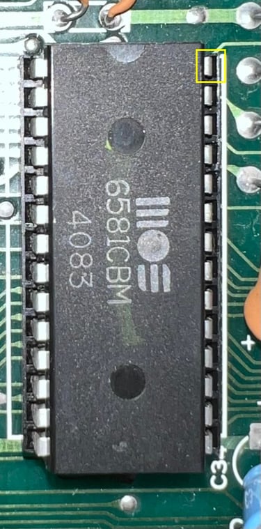
If you want, or need, to measure directly on the VIC-II chip you find the +5 V DC (Vvid) on pin #40 on the MOS 6567 chip. See picture below (yellow square - left side).

#4: CAN +5 V DC - Supply to the clock circuits (Vc)
This is a continuation of the 7805 voltage regulator supply shown above. To measure the +5 V DC for the clock circuit an easy spot is on pin #14 on the phase-frequency detector (4044). See picture above (yellow square - right side).
#5: +12 V DC - Supply to the VIC-II, SID and audio amplifier
The easiest place to measure the +12 V DC is directly on pin #3 on the 7812 voltage regulator.

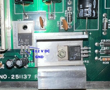
It is also possible to measure the + 12 V DC directly on the VIC-II, the SID and audio amplifier. Below are pictures of where the position is of the +12 V - and ground can be taken from any ground position on the mainboard.
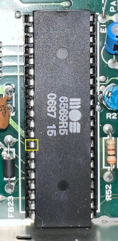
Pin #13 on VIC-II
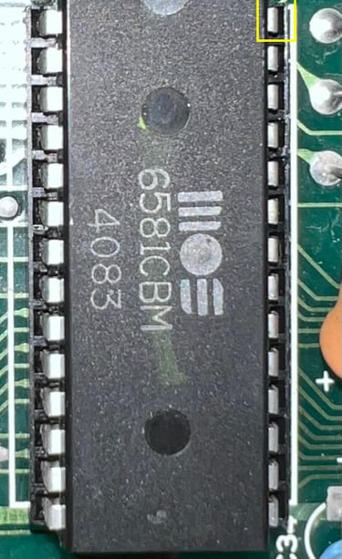
Pin #24 on SID
Collector on transistor Q8
#6: Unregulated +9 V DC - Supply to datasette motor amplifier circuits
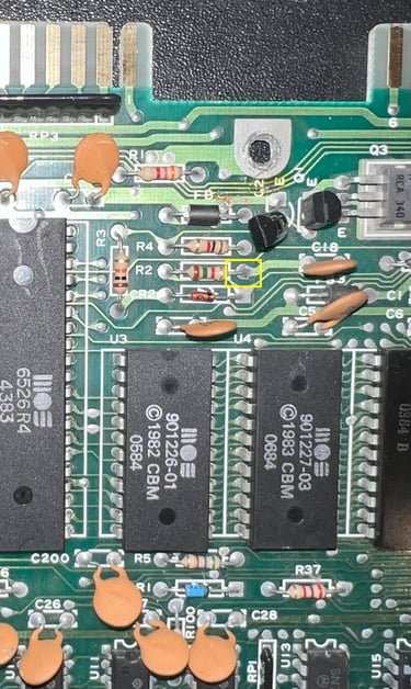
Most easy place to measure the unregulated +9V DC is at the R2 resistor. This resistor is found near the datasette port. See picture below.

C64 Mainboard voltages - Shortboard edition(s)
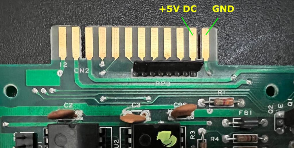
#1: 5 V DC - From the PSU
The easiest place to measure the 5 V DC which stems from the power supply (PSU) is at the user port. Pin #1 is ground (GND) and pin #2 is 5 V DC - the rightmost notch.
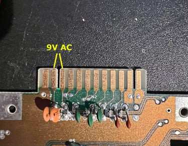
#2: 9 V AC - From the PSU
Just as easy as the +5 V DC the user port is a great place to check. The 9 V AC is found at pin #10 and #11 - the leftmost notch.

#3: Regulated 9 V DC
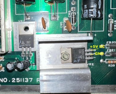
The easiest place to measure the +9 V DC (Regulated) is at the emitter of the Q5 transistor. The emitter is marked with an "E" on the board and is placed leftmost of the three transistor legs. See picture below (yellow line).
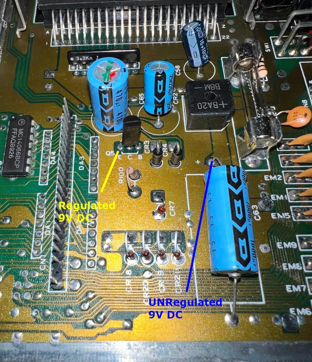

#4: Unregulated 9 V DC
In the same area as the regulated 9 V DC the unregulated 9 V DC is found also. The large 1000 uF (C63) electrolytic capacitor is a good place to measure the unregulated voltage. See picture above (blue line).
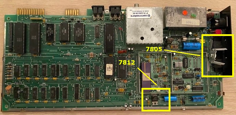
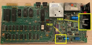
NOTE: The 7805 voltage regulator gets very hot! And it must be attached to a heat sink to transfer the excessive heat away from the regulator and to the surroundings/mainboard. A voltage regulator such as this one is designed to waste power in order to maintain a stable output voltage. And this waste results in heat. On older Commodore 64 mainboard, such as ASSY 326298, the 7805 voltage regulator is mounted close to the input power connector. If this 7805 voltage regulator on these older boards is not attached to a heat sink it is highly recommended that such a heat sink is installed! A 7805 which is damaged due to overheating can malfunction - and in worst case damage critical chips such as the VIC-II.
Below is a picture of an early revision of the Commodore 64 mainboard (ASSY 326298/REV A) where the 7805- and the 7812 voltage regulators are placed differently compared to later revisions.
Measured voltages - A reference
Longboard mainboard
The following voltages are measured on a Commodore 64 with mainboard assy 250407 artwork 251137 REV C longboard. The power supply (PSU) is a modern Electroware PSU C64 B/EU rated at 5VDC (4.0A) and 9VAC (1.1A).
Shortboard mainboard
The following voltages are measured on a Commodore 64C with mainboard assy 250469 artwork 252311 REV A shortboard. The power supply (PSU) is a modern Electroware PSU C64 B/EU rated at 5VDC (4.0A) and 9VAC (1.1A).