
HOWTO
Refurbish the C64 keyboard
Introduction
All Commodore 64 enthusiasts have been there… trying to press SPACEBAR or RETURN… but N-O-T-H-I-N-G happens! You press harder and harder… smashing the keyboard… and finally! Yeah! The Commodore 64 reacts to your keypress! Fingers hurt… but you managed! You passed the games crack intro! Ready to the next (key) challenge…
The Commodore 64 keyboard is in my opinion a good quality keyboard. But it do require maintenance to work properly. And after almost 40 years with neglected maintenance it is more likely that the keyboard requires a complete refurbish; broken plungers, yellowed keycaps, corroded springs, missing keycaps, dirt and grease and marginal plungers…
This HOWTO article will describe how I refurbish the Commodore 64 keyboard and hope that I can inspire others to refurbish their own keyboard.
Background theory
This is part contains background information about how the Commodore 64 keyboard works which can be useful when doing repair works or refurbishing.
The Commodore 64 use a keyboard with 66 keys. Two of these keys, the RESTORE and SHIFT LOCK, are special and will be described later. But the remaining 64 keys functions as small switches on the keyboard PCB. When a key is pressed, a plunger below the keycap is pressed onto the PCB. Since the end of the plunger consists of a conductive rubber with low resistance, and the PCB is made out of open copper- or carbon pads, this functions as a switch. When the switch is closed a low (ground) level signal is used to detect that is a key is pressed.
Instead of using a single wire for each switch the switches are cleverly arranged in a 8 x 8 matrix; giving a total of 64 positions. Each of these 64 positions represent a symbol / key as shown in the schematics below (retrieved from https://ist.uwaterloo.ca/~schepers/MJK/keyboard_int.html).
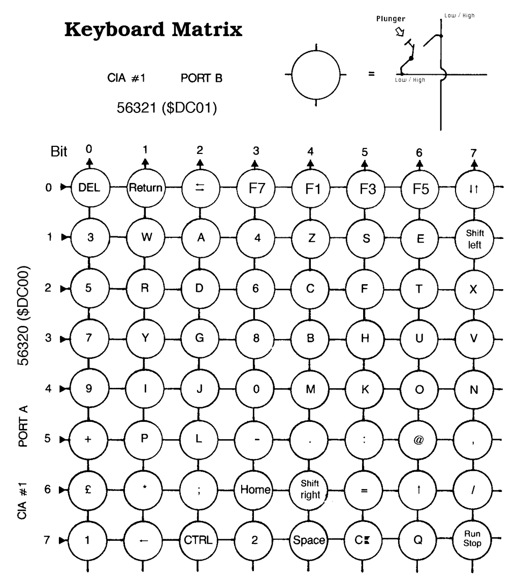

What is The Matrix?
The keyboard matrix is not complicated once you´ve understood how it works - and you don´t need to choose between red or blue pills at any point (!). In the matrix above we see that all the 64 key symbols are placed within a grid of circles. The circle is a representation of the switch composed of the key plunger and the copper/carbon pads on the PCB. On the top right of the schematics we see how this works:
If the circle input is "LOW" and the plunger is pressed the output is also "LOW"
If the circle input is "HIGH" and the plunger is pressed the output is also "HIGH"
Now, what is important to know is that when NO key/plunger is pressed all the eight bits output on PORT B are HIGH. So, when a user is not typing anything (the keyboard is idle) all the eight bits on PORT B are HIGH.
The principle behind the keyboard matrix is to SET the input and READ the output in the following way:
SET: One of the eight bits in the PORT A register in $DC00 (CIA #1) to LOW
READ: Check if one of the eight bits in the PORT B register in $DC01 (CIA #1) is LOW
As will be explained in a different chapter later the Kernal will set each of the input bits in PORT A to LOW in a sequential way, one-by-one. And then "listen" to PORT B to see if any of the bits go LOW.
Example
Let´s say that we have loaded the PORT A register ($DC00) with the value #%11110111. This would mean that bit 3 is set to LOW, and all the other bits are set to HIGH. Since the PORT A of CIA #1 is connected to the keyboard matrix the voltage level of the 3rd horizontal line is now 0 volts. If we now read what value is in the PORT B register ($DC01) and let´s say that we read the value "11011111". This means that bit 5 is LOW and all the other bits are HIGH. And again, since the PORT B of CIA #1 is also connected to the keyboard matrix we now measure 0 volts on the 5th vertical line. By checking the keyboard matrix we can now determine that the plunger for key "H" is pressed.
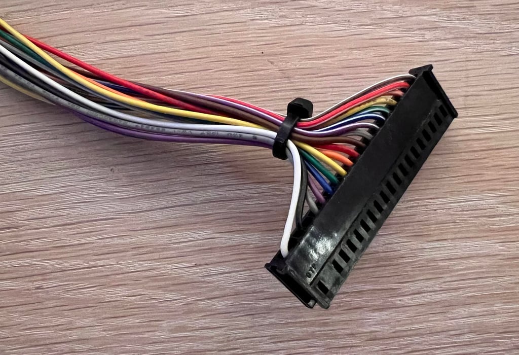
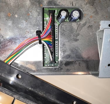
Connecting the keyboard to the mainboard
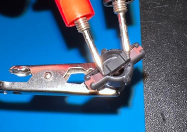
The keyboard is connected to the mainboard by a flat 20 pin connector (referred to at CN1). Although it is common that only 18 of these are used.
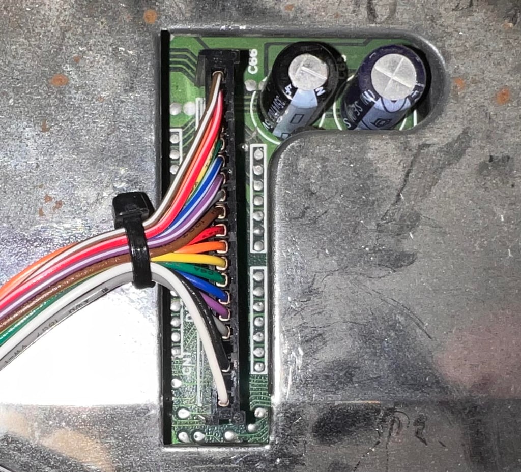
In the schematics below we can see that all of the 16 wires (from the 8 x 8 matrix) are directly connected to the MOS 6526 CIA #1 chip. The inputs are named "PAx" and "PBx" for PORT A and PORT B respectively. Also, note that these 16 lines are often referred to as columns and rows.
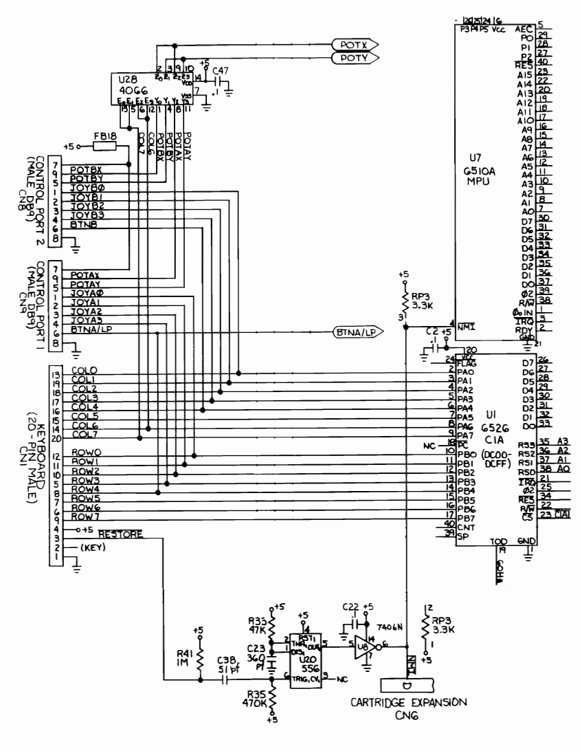

From the schematics (taken from the C64 Service Manual) we can also see some additional things:
Both joystick ports are connected to the same bus that goes into PORT A and PORT B on the CIA #1. If you have sometimes seen characters printed on the screen while the joystick is connected you now can see why. So when refurbishing or repairing a Commodore 64 make sure that your joystick doesn´t play you a trick...
The RESTORE key is indirectly connected to the MOS 6510/8500 CPUs NMI input. The NMI is an acronym for "Non-Maskable Interrupt" basically saying that if an interrupt is detected on this pin the CPU will go to the NMI interrupt vector no matter what. It is not possible to "mask" this interrupt request (which is not entirely true, but that is another story...)
When repairing or refurbishing the Commodore 64 keyboard / mainboard it can be a bit hard to follow the schematics since the ordering of the pins on the connector are not in increasing order. Therefore I have this sketch which I think is easier to follow:


How is the keyboard scanned for keypresses?
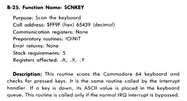
When the Commodore 64 is in default operation (the normal blue boot-up screen) the KERNAL ROM is active. The KERNAL ROM is a library of operating subroutines required for Commodore 64 to function in default mode, and one of these routines is the "SCNKEY" which scans the keyboard. See description below (from the Commodore 64 Programmers Reference Guide").

This routine is called by the KERNAL operating system as part of the default interrupt service (default IRW). We can expect this to be every vertical blank - that is each time the screen is re-drawn the keyboard is scanned for a keypress. On a PAL machine this the frame rate is approximately 50 times pr. second, so each 1/50 s = 0.02 s the keyboard is scanned.
The way that the KERNAL scans the keyboard matrix is approximately like this:
The first bit in register $DC00 (PORT A) is set LOW
Bit 0 to 7 of register $DC01 (PORT B) is read. If any of these bits are read as LOW then a key is detected and the routine exit. If all of the eight bits in $DC01 are read as HIGH the routine starts over again with the next bit in register $DC00 set to LOW.
So by writing column values in sequence (in register $DC00), then reading the row values (in register $DC01) the KERNAL detects the switch closures.
The KERNAL routine for SCNKEY can be found at memory address $EA87 (note that the address $FF9F is just a jump address to $EA87 for this KERNAL ROM version). You can find the complete listing elsewhere, but as shown in the picture below it is easy to see that the $DC00 and $DC01 are in operation in the SCNKEY routine. The disassembly is done with the Super Snapshot monitor on a stock C64C.

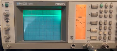
We can also use an oscilloscope to see the KERNAL routine setting the $DC00 bits to LOW in sequence. As previously mentioned this happens as part of the default KERNAL IRQ routine which is about each frame re-refresh (at 1/50 second). In the picture below pin #19 is probed (bit 1 on PORT A). With the oscilloscope we see that we get a small "dip" to 0 V at approximately each 0.015 seconds (my oscilloscope is not accurate enough). This small "dip" is when the KERNAL set bit 1 of the register to LOW.


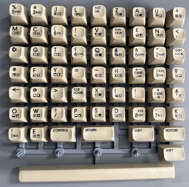
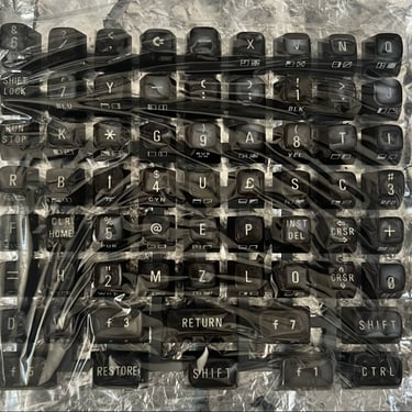
Visual inspection
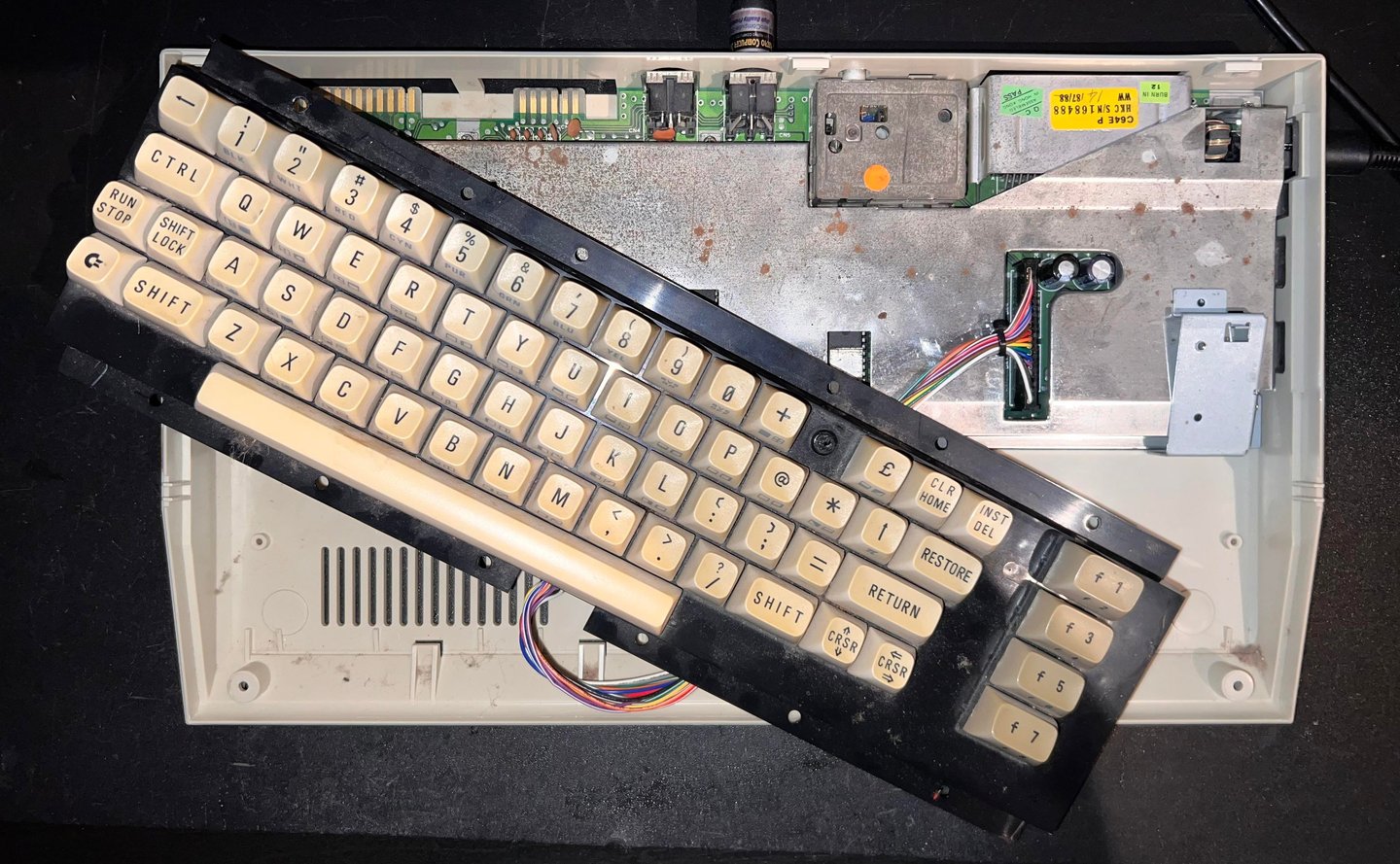
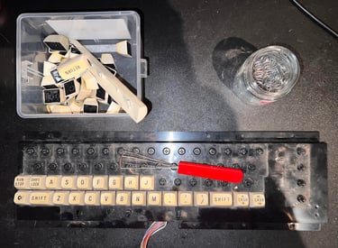
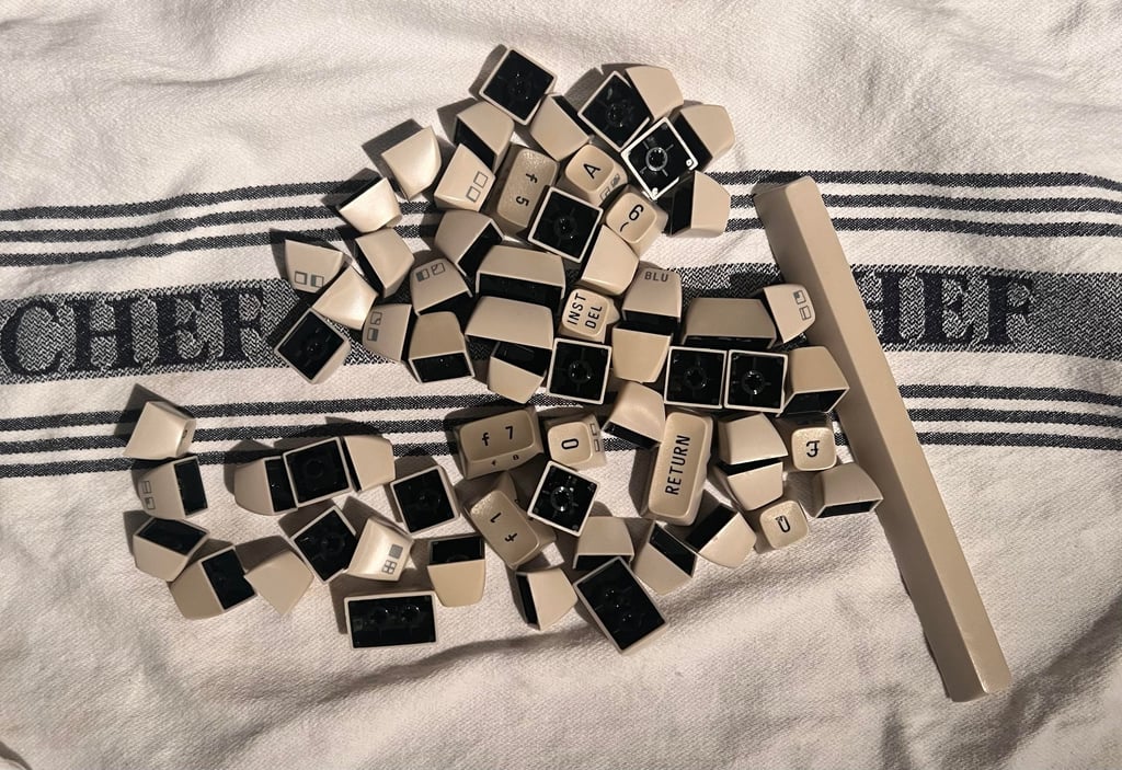
A good starting point for refurbishment or repair is with a visual inspection. How does the keyboard look? Anything obviously wrong, missing parts or major damage? Any of the keys feeling “odd” compared to the other?
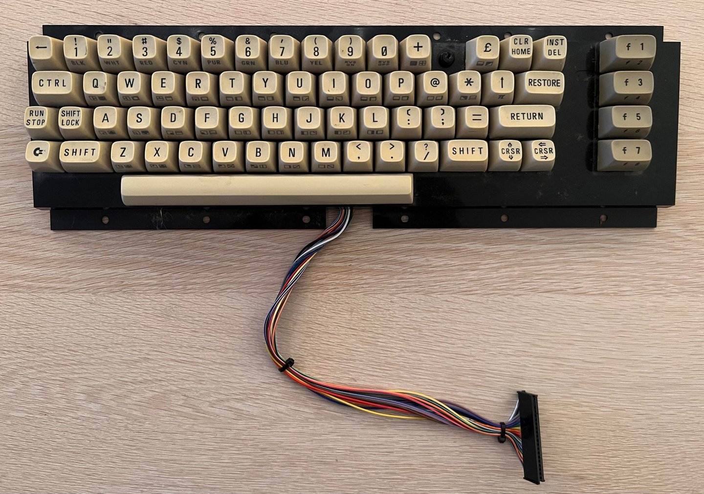
With this keyboard I note the following (see picture below):
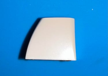
The “-“ keycap is missing
One spring is missing
One plunger is broken
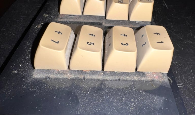
The “F7” appear to be more sticky than the other
All keycaps are quite yellowed
A lot of dirt and grease under the keycaps


Initial testing
Before refurbishment it is good practice to check the function of the keyboard. Some areas to check:
Does the Commodore 64 register the keys when they are pressed? All? Some?
Is there a group of keys not working at all? Could be a sign of an oxidized connector or broken wire.
Are there some keys which needs to be pressed harder in order to be registered as a key press?
Does the SHIFT-LOCK key work? Does the Commodore 64 print the symbols when characters are pressed?
This keyboard is actually functioning quite good. Some of the keys needs to be exposed to a bit more pressure before a key press is registered, but most of the keys are working fine. Nevertheless, for the purpose of this HOWTO article all the keys will be completely refurbished.
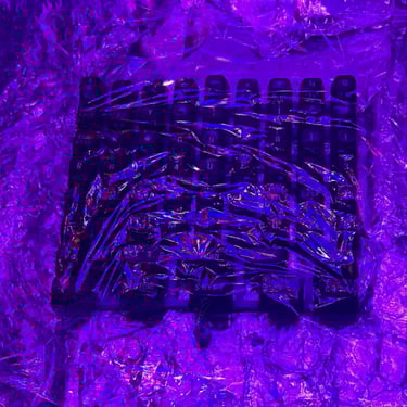
Below are some pictures from the initial testing.

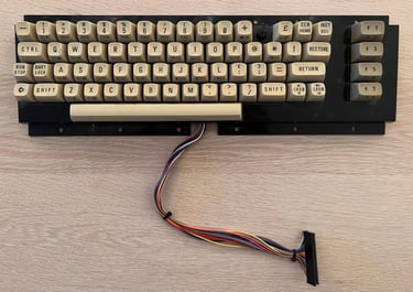
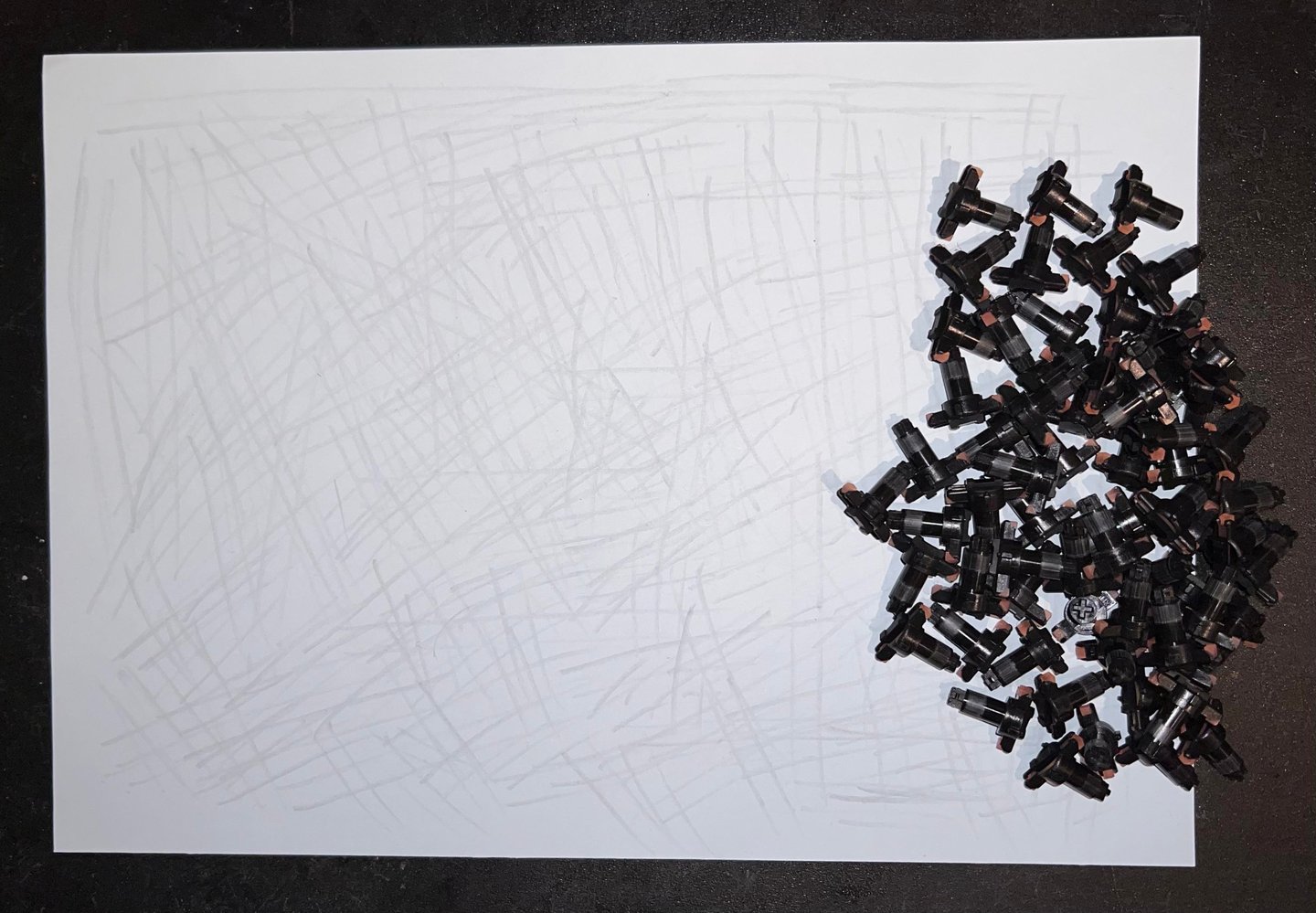
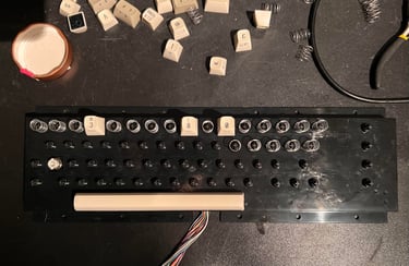
Removing the keycaps
To remove all of the 66 keycaps it is highly recommended to use a keycap puller. With this tool you reduce the risk of damaging the keycap and/or the plunger below that otherwise needs to be removed with a flat screwdriver or your bare fingers. You can buy these keycap pullers cheap from webshops such as eBay and Aliexpress.

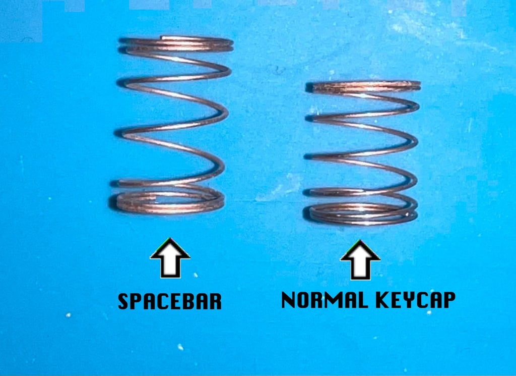
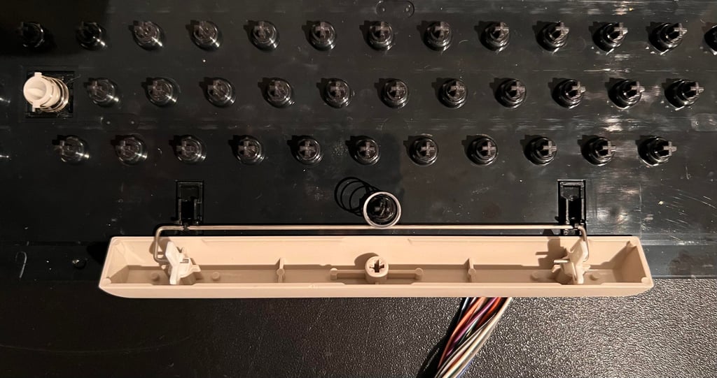
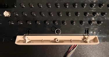
The first key to remove should be the SPACEBAR. The reason for the is simple, but important:
The spring beneath the SPACEBAR is larger than the rest of the springs beneath all other keys
It is good practice to keep this spring in a separate plastic bag to make sure you don´t mix them up. Even if the spacebar spring is larger, it is not significantly larger as can be seen from the picture below.

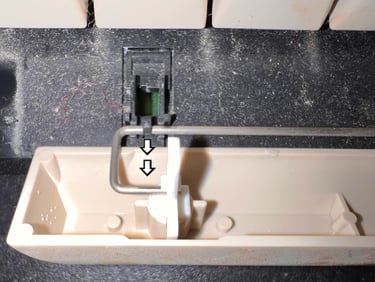
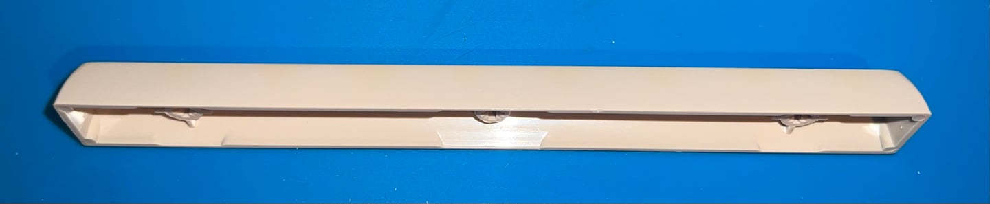
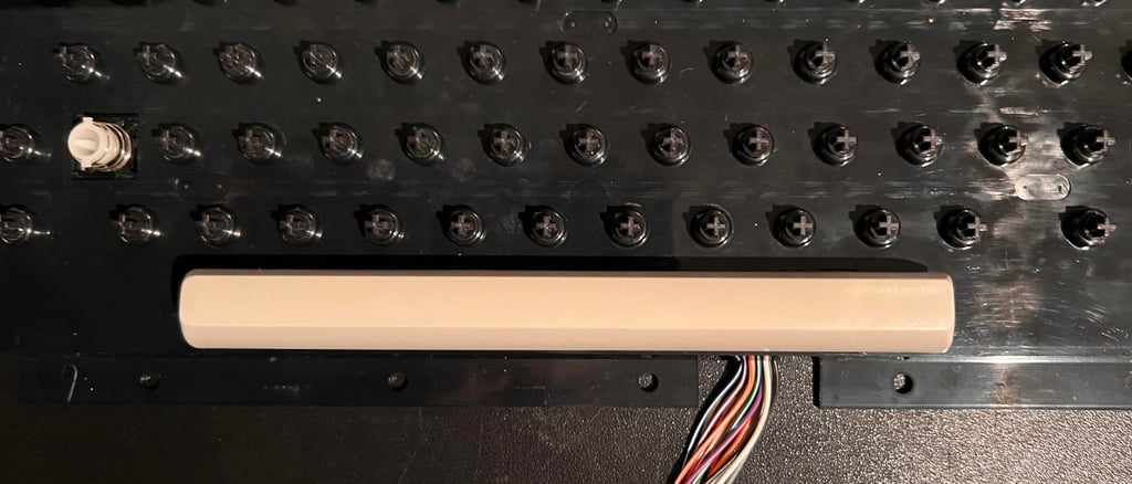
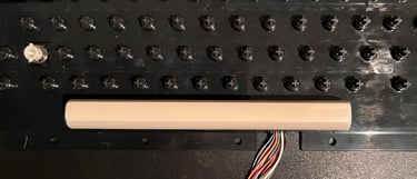
The spacebar is attached to plastic casing by a long metal bracket mounted on a clip on each side. To remove the metal bracket from the plastic clips it is pulled downwards with a pair of pliers.
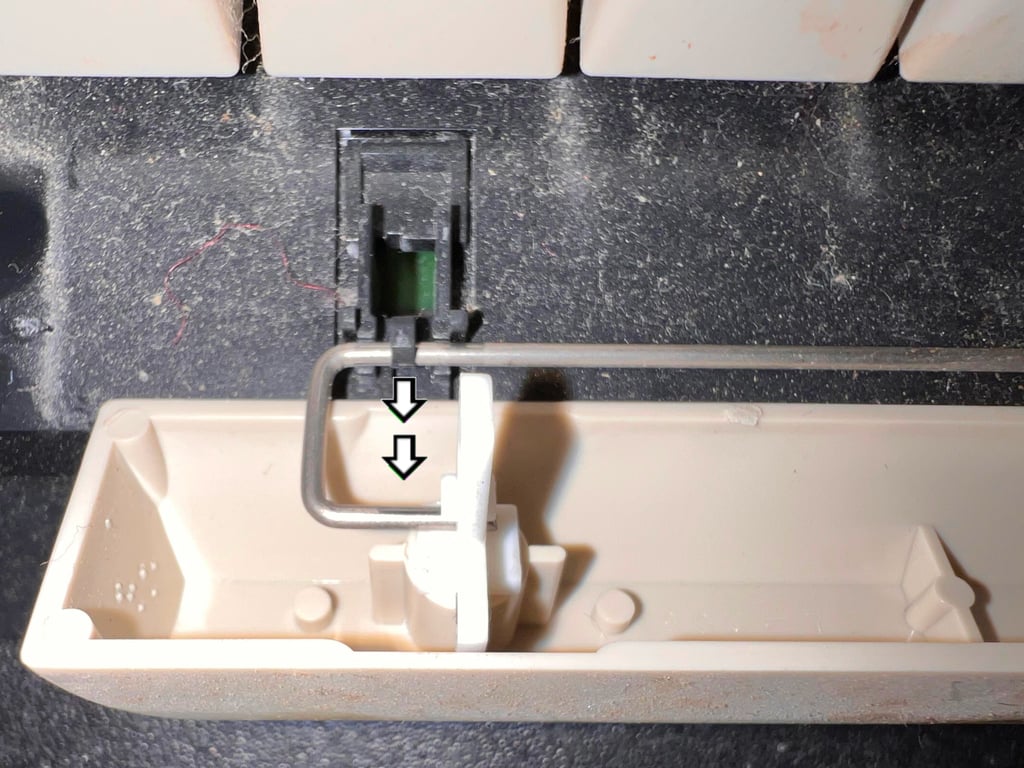
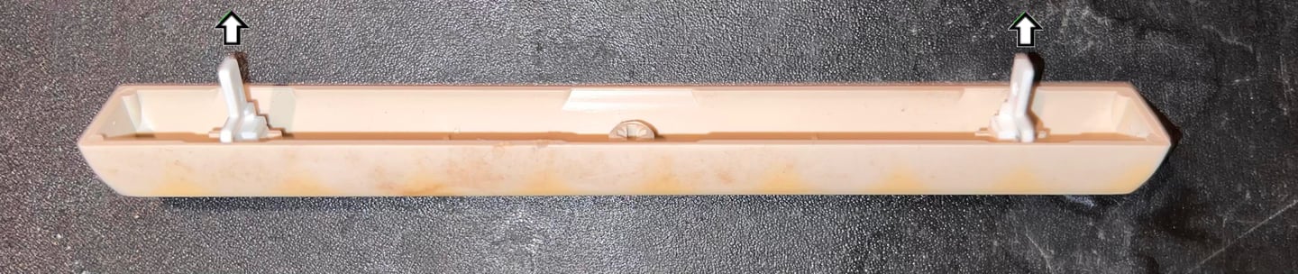
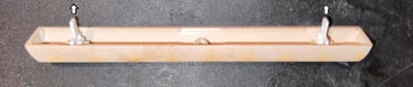
To make sure you don´t loose the two small plastic insert clips it is wise to remove these also. With a pair of pliers these are pulled out of the spacebar and placed in a small bag.
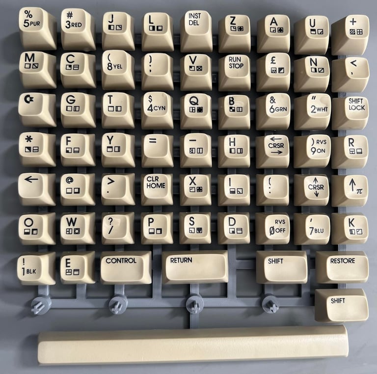
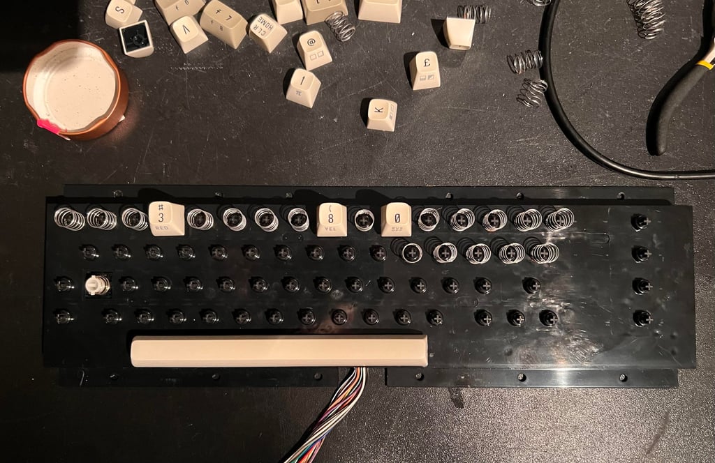
With the keycap puller all of the keycaps are removed. As mentioned above, some of the keycaps can be a bit "stubborn" requiring a firm pull to get if off the plunger. So even if the keycap puller is a great tool, it is important to be careful to make sure you don´t damage the either keycap or plunger.

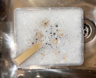
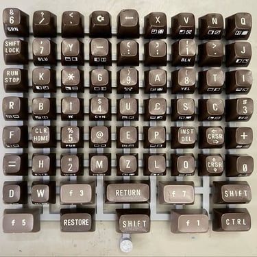
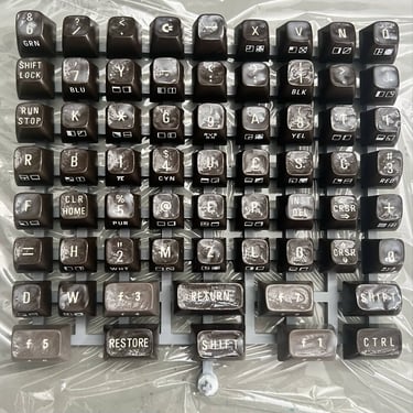
All of the keycaps are placed in a box of soap water and some glass cleaning spray. The keycaps are left in this bath for about 12 hours to make sure all the grease is dissolved.

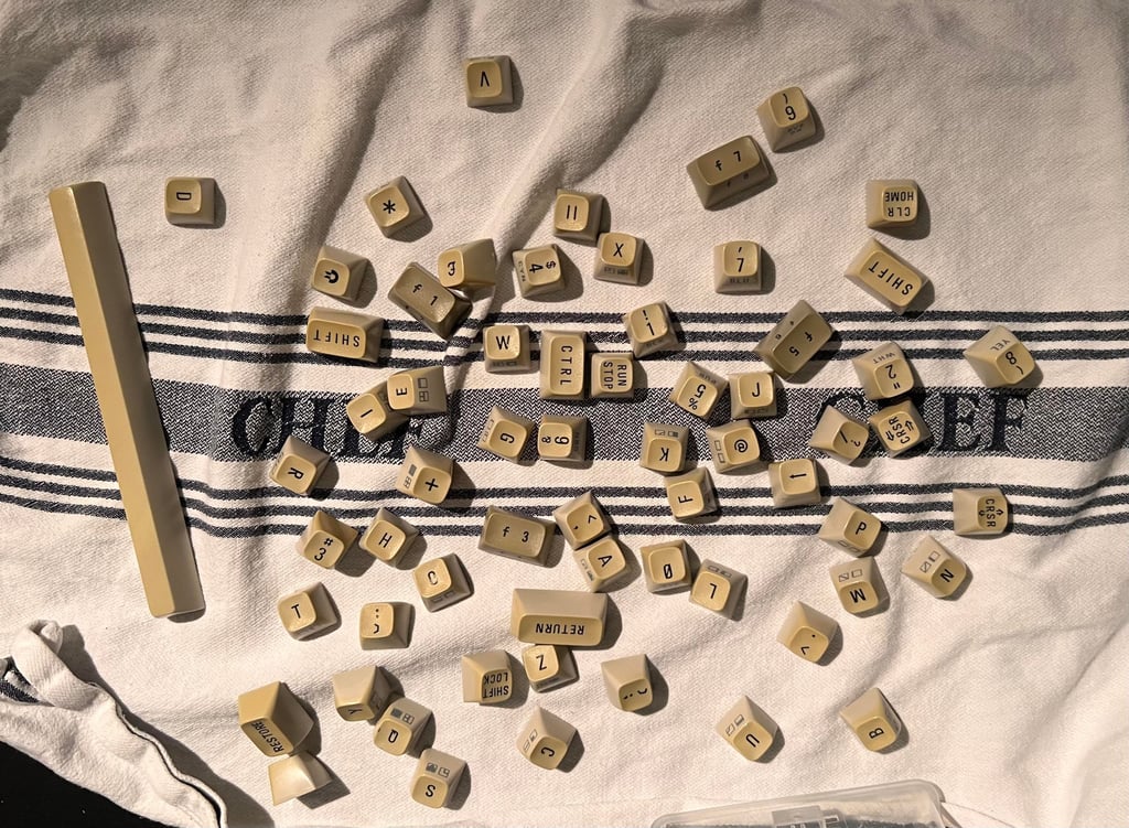
After cleaning the keys are left to dry. They look much better than before - still very yellowed, but all of the dust and fat are gone.

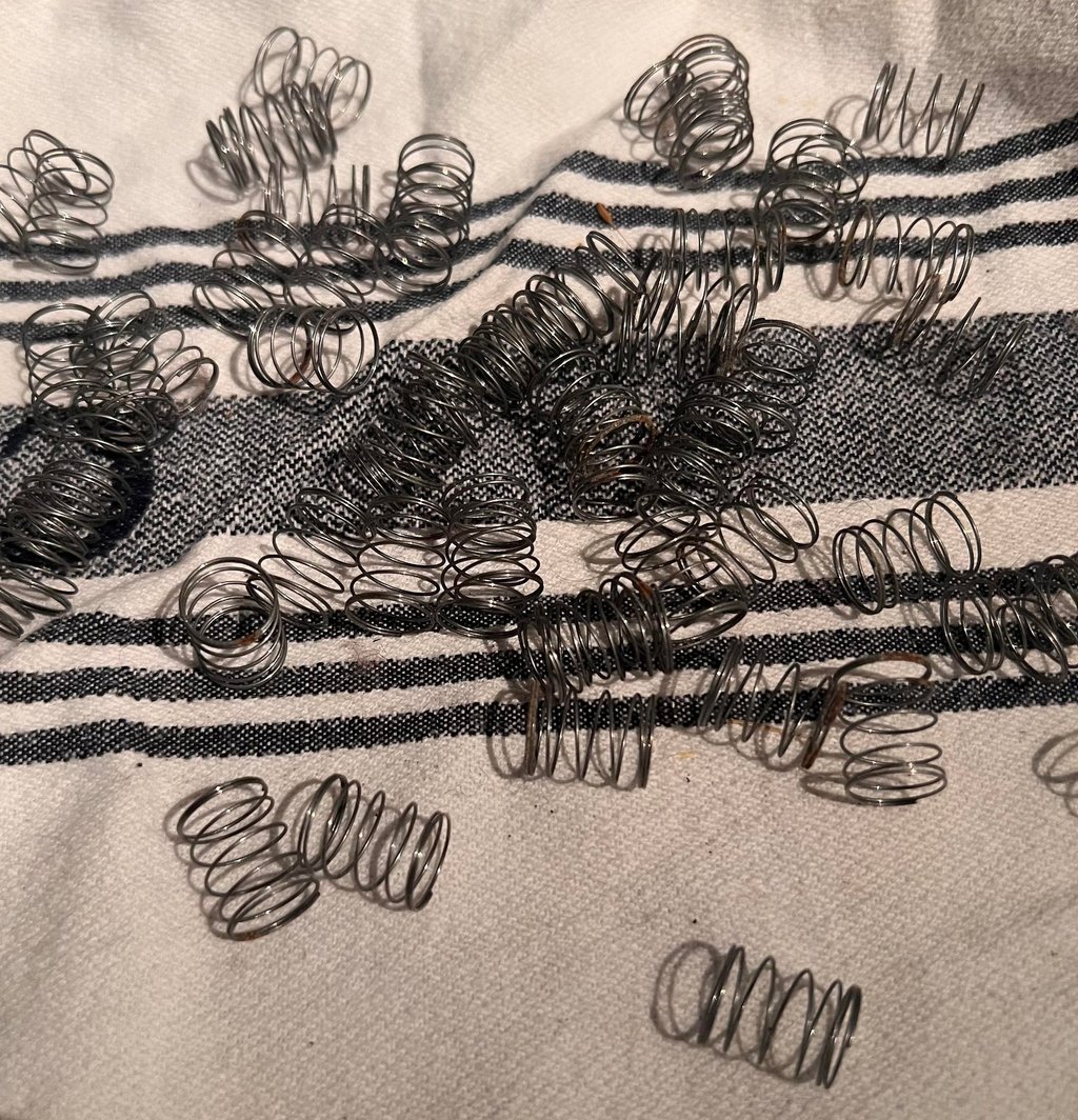
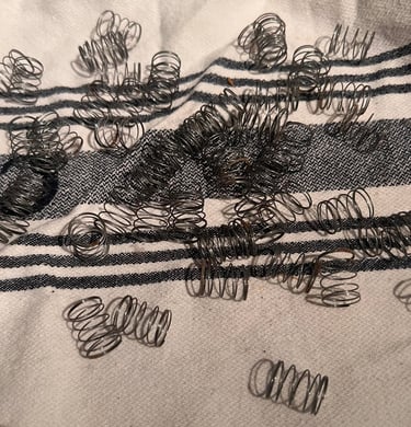
The springs are freed from dust and checked for corrosion. It´s common that there are some corrosion on the springs. If it is severe it can be removed with some diluted vinegar (and then some water afterwards) and Q-tip. Also, the springs can be sprayed with some WD-40 to prevent further corrosion. Below is a picture of the springs after the dust has been removed.
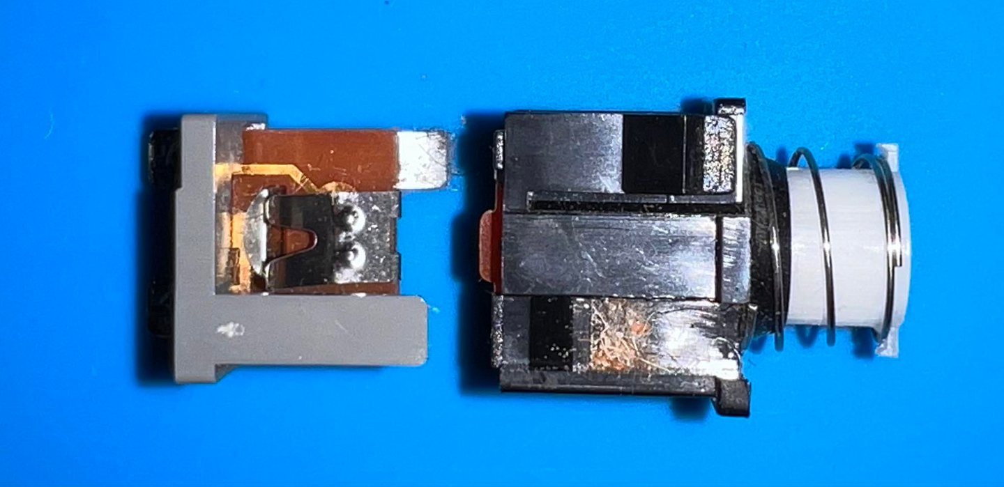
SHIFT-LOCK service
The SHIFT-LOCK key needs to be removed before the keyboard can be completely disassembled. But the SHIFT-LOCK key can also benefit from some proper service. But first, the SHIFT-LOCK needs to be desoldered from the two wires.
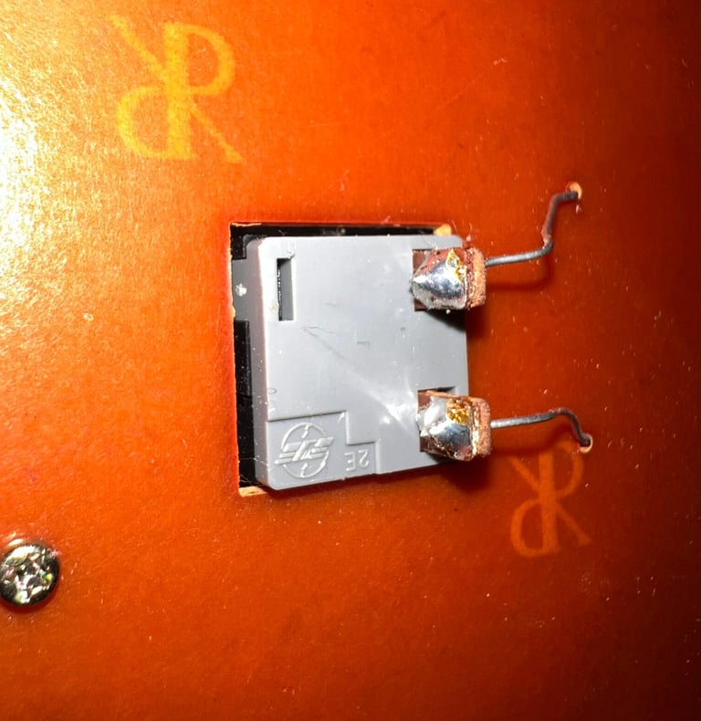
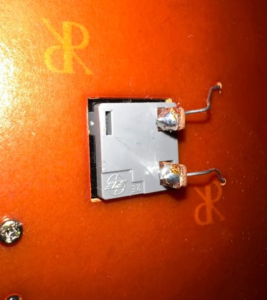
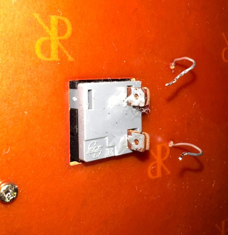

To get the SHIFT-LOCK key out of the keyboard it is pushed firmly from the backside and towards the front. The SHIFT-LOCK key will then pop out of the keyboard. It is normal that this key can be quite dirty - both on the outside, but also on the inside (!).
The exterior of SHIFT-LOCK key is cleaned lightly before it is opened. To open the SHIFT-LOCK key a small flat screw driver is positioned beneath the two plastic tabs in sequence.
By separating the two parts the SHIFT-LOCK key consists of, it is now ready to be cleaned. To clean the interior of the key, a (small) Q-tip with isopropanol is used. Finally, the interior is sprayed with contact cleaner. Below is a picture of the disassembled SHIFT-LOCK before cleaning.
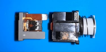
When the key is cleaned it is re-assembled by gently pushing the two parts together again. Then the exterior is properly cleaned at last.

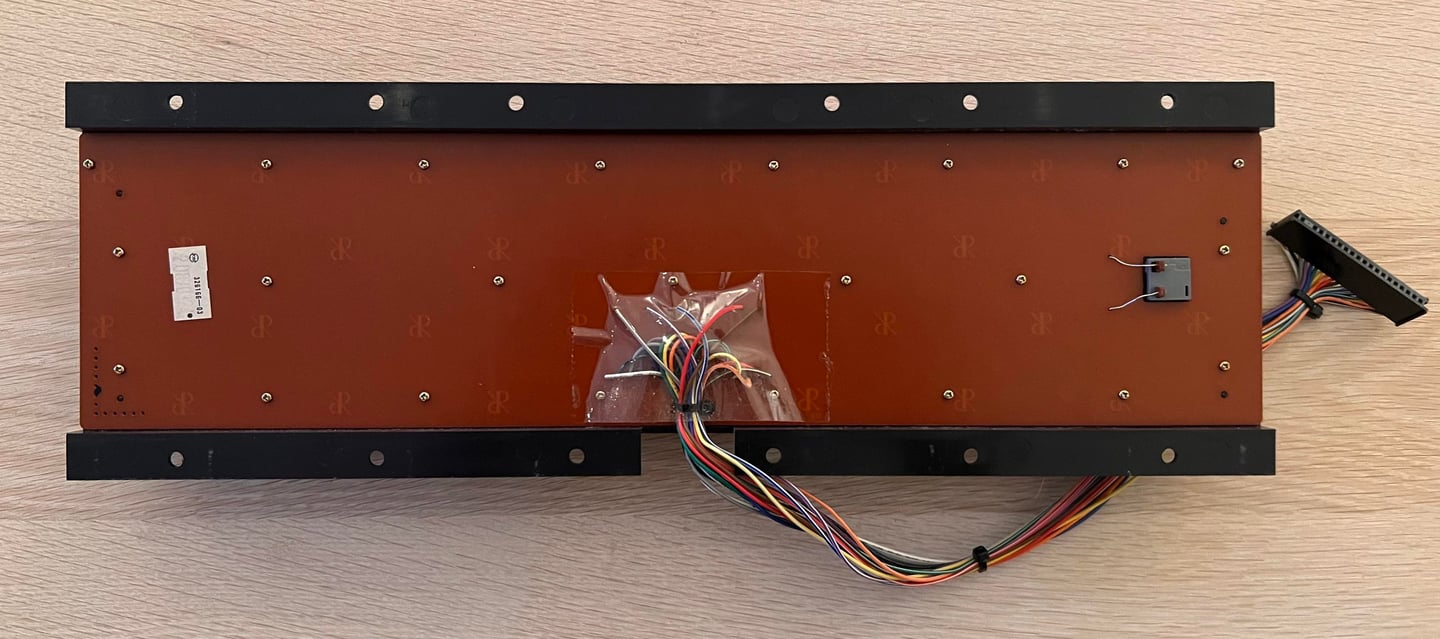
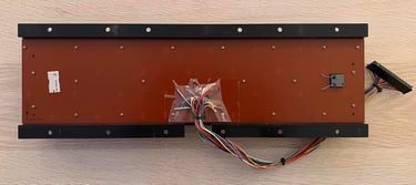
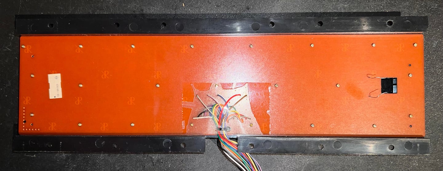
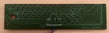
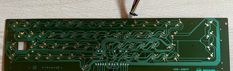
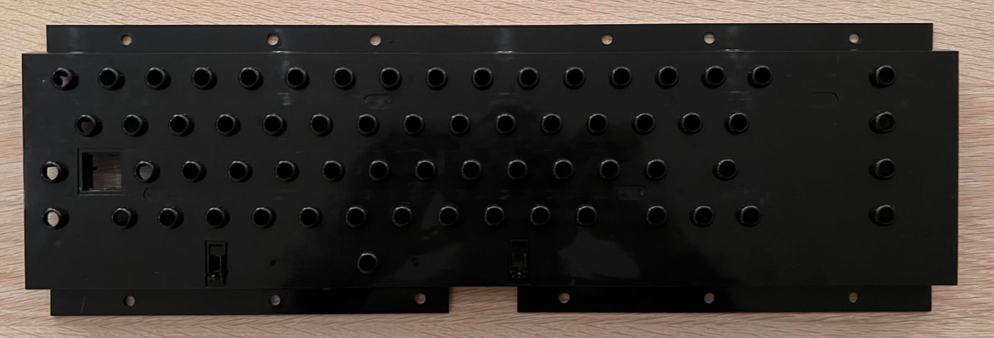
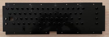
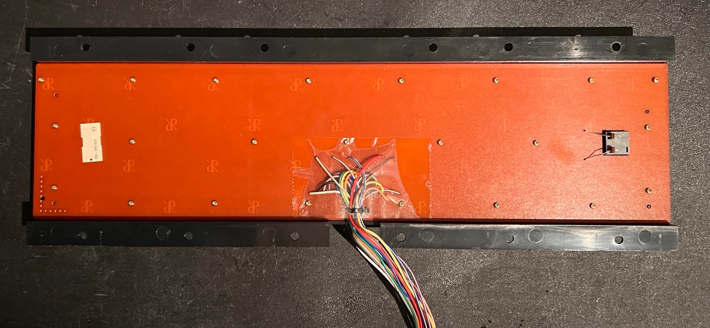
Keyboard PCB
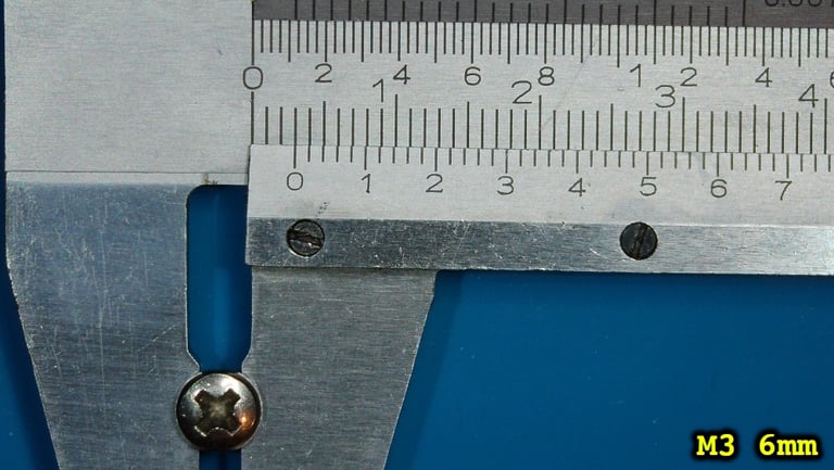
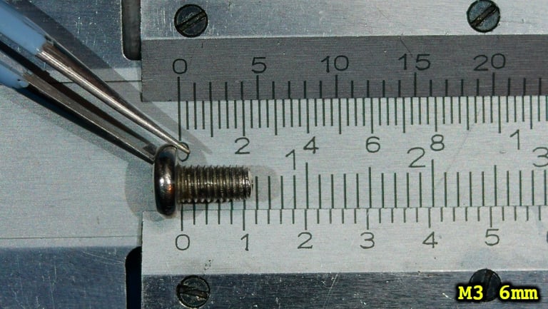
The keyboard PCB is fixed to the plastic casing by 23 small screws (feels like a million screws). So the first thing to do is to remove these screws and then lift the PCB out of the casing. Note that it is good practice to place these tiny screw in a small plastic bag or some container to avoid loosing some of them.

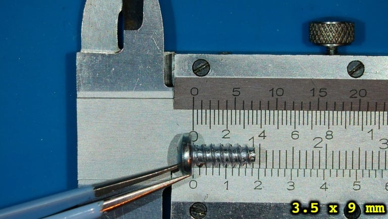
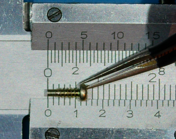
The small screws have the following properties:
Phillips pan head (PN): 3.5 mm
Partially threaded (non-threaded shaft at bottom)
Thread diameter: 2 mm
Fastener length: 6 mm

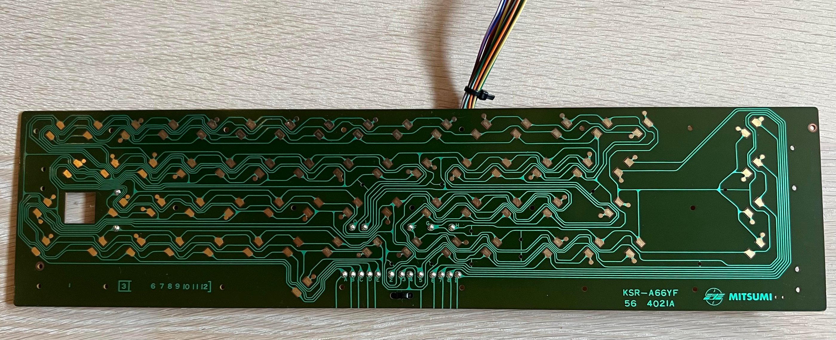
The Mitsumi KSR-A66YF also come in a slightly different version with copper pads instead of carbon pads - the KSR-A66YF 56 4021A (aka the "A" version"). These kind of PCB I clean with isopropanol to make sure that all the exposed copper pads are free from dust and grease. See picture below.

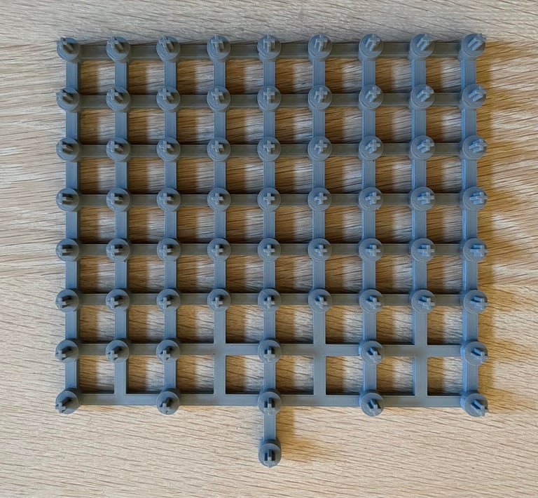
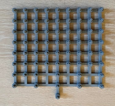
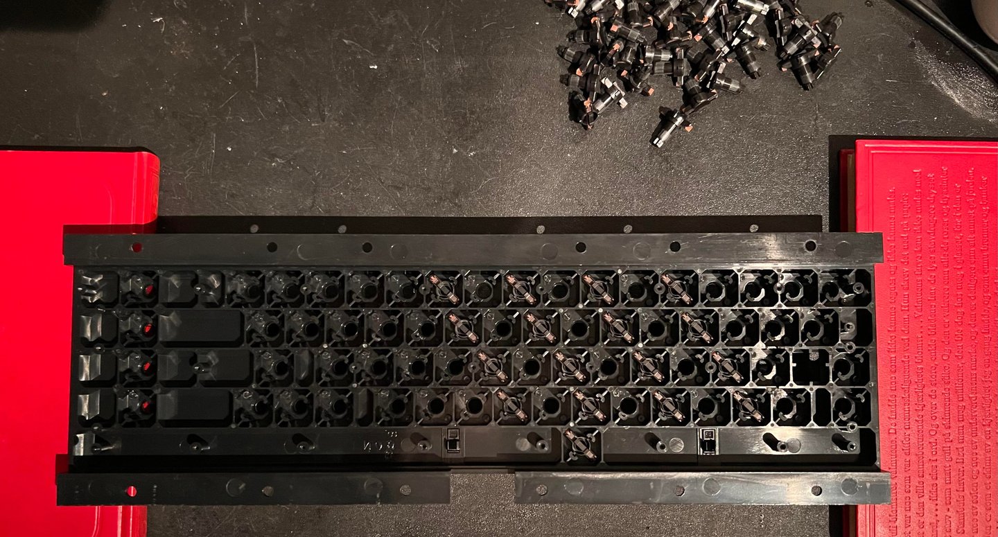
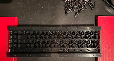
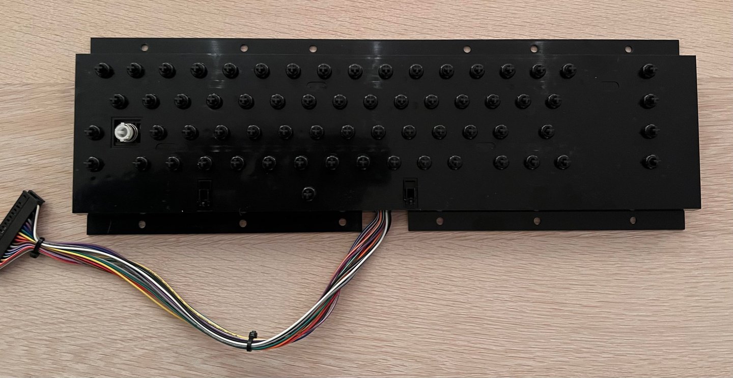
Cleaning the plunger casing
The plastic casing holding all the 66 plungers is usually very dirty. After almost 40 years it is normal that this plastic casing is full of dirt, grease and scary germs.
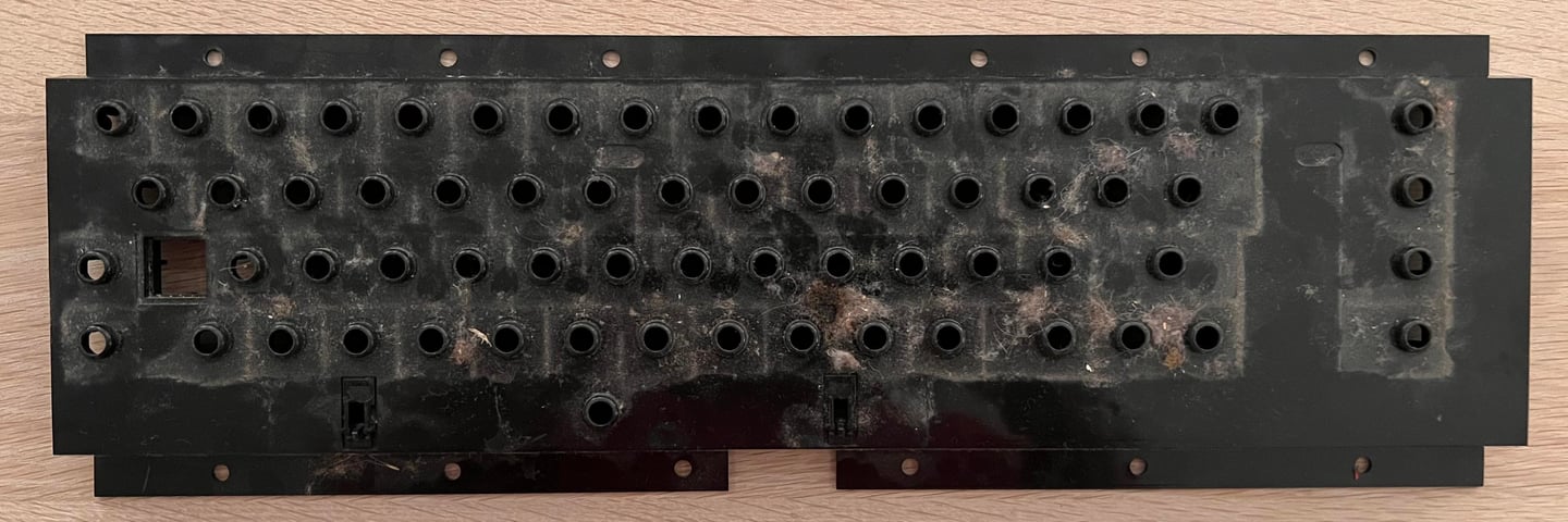
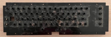
Cleaning the plastic casing is straightforward. A lot of mild soap water and a clean paint brush do the work. It may require washing a couple of times before all the dirt and grease is gone. But the result is normally very good. Looks as new?
Reviving the plungers
A good functioning Commodore 64 keyboard requires that the plungers are working as they should. After several years stuck inside the keyboard the the conductive rubber at the end of the plungers can be dirty or greased. And if so, this can reduce the conductivity with the consequence that key presses are not registered at all, or that you need to push real hard for the key to be registered.
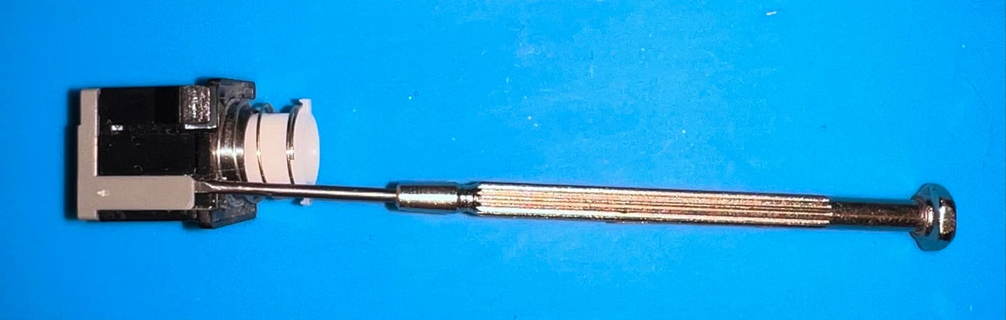
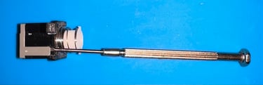
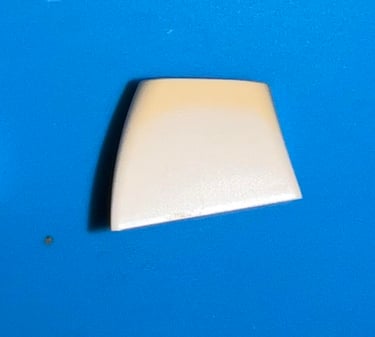
The plunger consists of a shaft with the conductive rubber at one end and the tip for the key in the other.

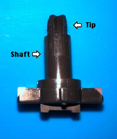
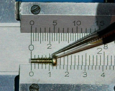
Note that there are some variations of the plungers. The tip can vary between about 3 - 5 mm, and there are some variations on the form of the conductive rubber. So if you need to purchase a "new" plunger make sure to get the correct one.
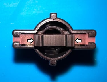
Below is a picture of the conductive rubber on a typical plunger. The conductive part is the dark rubber between the two arrows.
Quite ofte, but not always, the conductive rubber on the plungers can be revived. There are two ways of doing that:
Clean the plunger by dragging the conductive rubber over a piece of paper
Clean the plunger by using isopropanol on a Q-tip on the conductive rubber
Which is the best? In my opinion it is the former. By dragging the conductive rubber carefully over a piece of paper this both cleans the plunger, and is also the most effective and less damaging. For time to time it is necessary to do both to revive them.
Below is a picture where all plungers have been cleaned by using the first technique. It is important that you do this carefully so you don´t damage the conductive rubber.

Plunger still doesn´t work? Measure the resistance!
As mentioned it is not always possible to revive the plungers. The reason is that the conductive rubber could be so deteriorated that it no longer is conductive. This is not possible to see with visually, but you can measure it with a multimeter. By carefully placing the two leads from a multimeter at both ends of the conductive rubber you can measure the resistance in Ohm (you can see where the ends of the conductive rubber are in a previous picture).
Note that it is not easy to neither hold the plunger in place or to get a steady reading in Ohms. It can be wise to place the plunger in some "helping hands". If the plunger is ok the conductive rubber should be in the area of approximately 75 - 300 Ohm (and the reading can be volatile).

Another useful way of measuring the resistance is probe the keyboard connector while the keyboard is fully assembled. This can be relevant in the cases where you have revived all the plungers, but some of the keys are still not working as they should. By measuring some of the individual plungers you can identify if some of them are simple defective and needs to be replaced.
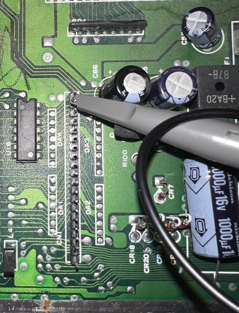
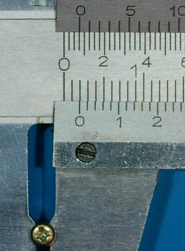
As an example let´s say that we think that there is too high resistance on the "DEL" key after cleaning and assembling. From the background theory chapter we know that this key is in column 0 and row 0, and that correlates to pin 12 and 13 on the keyboard connector. The keyboard connector have small openings on the side which can be used for probing with a multimeter.
So with the keyboard fully assembled, the "DEL" key is pressed down - and at the same time the two multimeter probes are placed at connector pin #12 and #13. See picture below. In the same way any suspicious key can be measured. First find the row/column, then the connector pin and finally measure the resistance while the key is pressed.

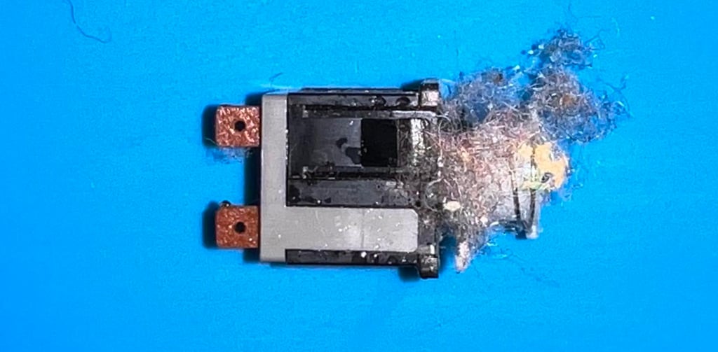
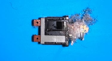
Broken key plungers? Fear not!
Plungers can break. The plastic is old and brittle, and from time to time it happens that the plungers break either when removing the keycaps or when banging the keys. But fear not! These can be replaced either by:
3D printing a new plunger if the conductive rubber can be re-used
Purchasing replacement spare plungers with conductive rubber
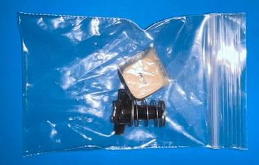
In the sample keyboard used in this article the latter option is used since the "-" keycap is also missing. A new new keycap, spring, plunger (with conductive rubber) is ordered from retroleum.co.uk.

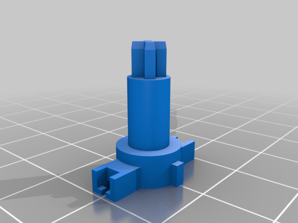
Replacement plungers for 3D printing can easily be found on websites such as thingiverse. There are some variations between the plungers so make sure you print the correct version.
Retrobrighting the keys
After 30-40 years it is common that the Commodore 64 keys have become yellowed. Even if this is only cosmetic it is nice to do some retrobrighting to get the keycaps back to the original color (more or less). Yellowing can occur in many variants:
All keycaps are completely yellowed
Some keycaps are yellowed others are not
Yellowing on certain areas on some of the keys (spots)
Part of the keycap yellowed (typically the top)
WARNING: The old brown keycaps, found in the first Commodore 64 machines, have very fragile printings. The symbols found on the front of the keycaps are likely to be damaged/disappear when doing the retrobrighting. Why do retrobrighting of brown keycaps? The reason for this is that the top letter, in contrast to the front symbols, yellow the in the same manner as the white keycaps.
In the pictures below are some examples of yellowing. On the spacebar some areas are more yellowed than other, and on the single keycap the top of the key is more yellowed than the bottom.


There are two ways to best retrobright the keycaps:
Placing the keycaps in a plastic bag filled with 12 % hydrogen peroxide cream (slower, but does not require monitoring during the process)
Placing the keycaps on a 3D printed bracket and applying 12 % hydrogen peroxide cream (faster, but require more monitoring and follow-up)
Placing the keycaps in a plastic bag
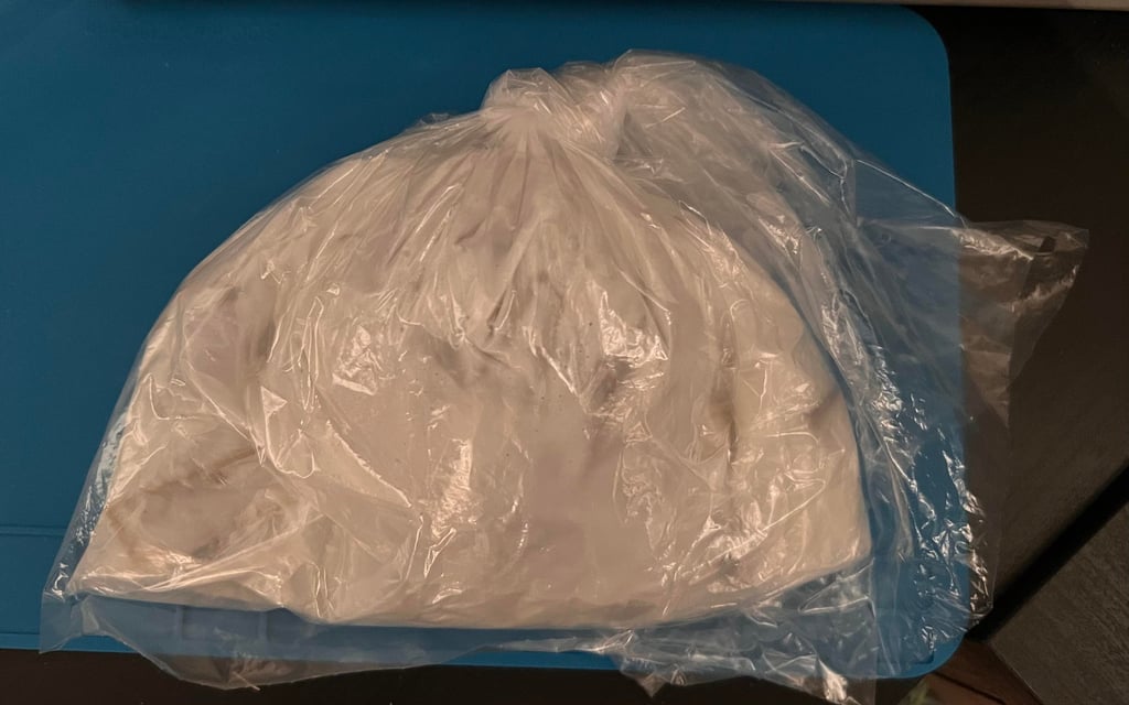
For retrobrighting you can use 12 % hydrogen peroxide cream. All the (clean) keycaps are placed in a plastic bag filled with about 3 dl of hydroperoxide cream and "massaged" to make sure every single keycap is encapsulated in cream. This can be quite a slow process depending on the severity of the yellowing. For the keycaps above the total time in the plastic bag is about two weeks. Half way the keycaps are taken out of the cream, washed and then placed in a bag of new cream again. Also, for about two days the keycaps are exposed for UV-light.
Below is a picture of the keycaps when placed in the bag filled with 12% hydroperoxide cream. Note that after a week the cream is replaced with fresh cream. Total time in the bags is about two weeks.
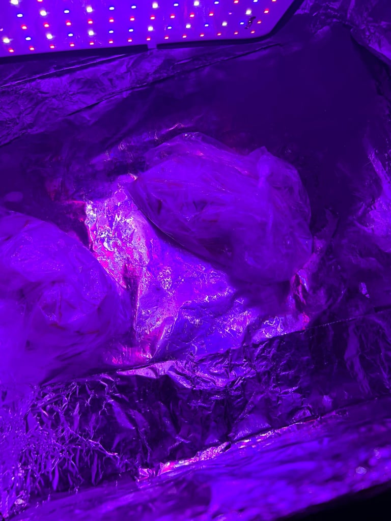
To speed up the process the keycaps are also exposed for UV-light for a couple of days. In summertime its great to place the bag outside in direct sunlight, but during wintertime the bag is in a box with artificial UV-light.

Placing the keycaps on a 3D printed bracket
The biggest challenge (unless you put all the keycaps in a bag) is to apply the hydrogen peroxide cream to the keycaps evenly without a big mess. Everyone who has tried this know that the result is that keycaps are floating around with hydrogen peroxide cream all over the place. The solution to this problem is: the Commodore 64 KeyCap Mount for easy retrobrighting (designed by kbotragyi). This is a 3D printed plastic bracket which will hold, and align, all the keycaps. Making the process of applying the hydrogen peroxide cream evenly way easier.
Result from the retrobrighting is good. Most of the yellowing is gone - look like new?


Reassembly
After everything is cleaned and revived it is time to reassemble the keyboard. This is done by - surprise! surprise! - doing the process in reverse. First all the plungers are put back in the plastic holder. Note that the plastic holder needs to be lifted from the table. To do this a couple of books can be used to provide the sufficient gap between the table and the plastic holder.
The keyboard PCB (functioning as backplate) is mounted and all screws put back in. Finally, the SHIFT-LOCK key is put back in. To insert the SHIFT-LOCK key push it from the front of the keyboard towards in the back. The key will "pop" in place. Both wires on the SHIFT-LOCK are soldered to the key.
TIP: When mounting back the 23 screws make sure to first screw counter-clockwise until you feel the screw "fall in place". Then screw clockwise. If you do this you reduce the risk of damaging the plastic screw holes.
The keyboard is turned in upright position and all plungers are checked to see if the are moving freely. As can be seen from the picture below the result from the cleaning is now becoming obvious. It looks almost new?

When replacing the keycaps it is good practice to start with the spacebar. The two small plastic insert clips are mounted, the metal bracket is put back in together with the larger spring. Then the spacebar is carefully moved into position.
Now all the remaining springs and keycaps are put back again (when inserting the keycaps be careful not do damage the plungers).
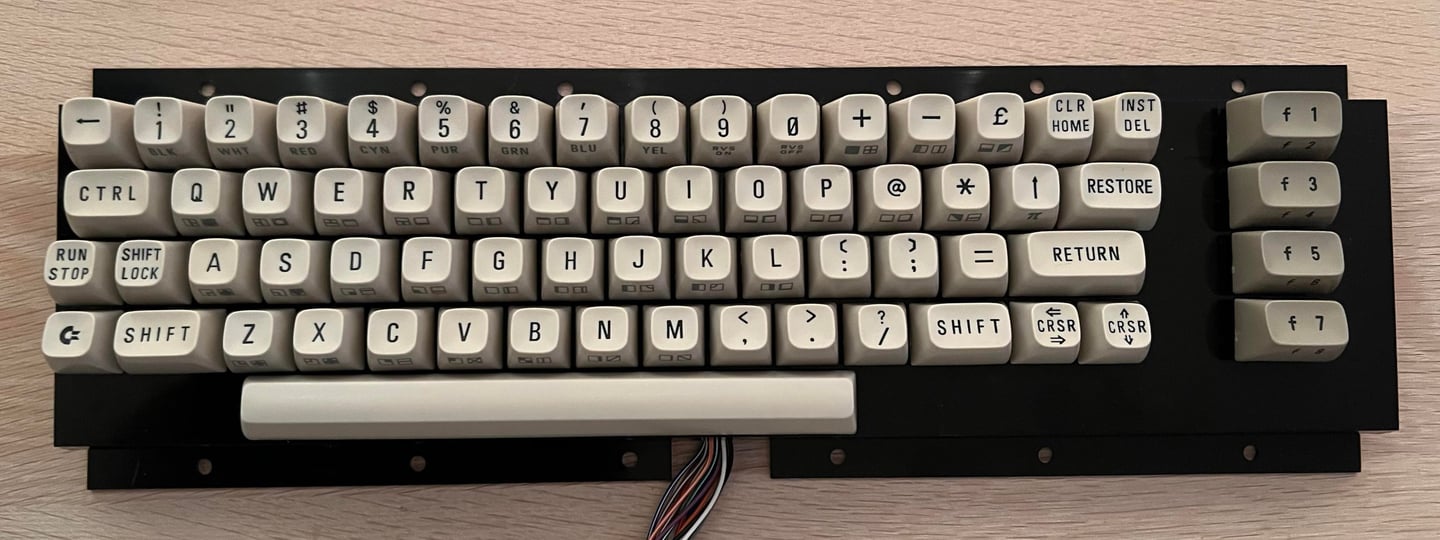
With all the keycaps in place the keyboard is complete - cleaned, revived and retrobrighted!
Final testing
To make sure the refurbishing was a success the keyboard must be testet. I recommend doing this in two stages:
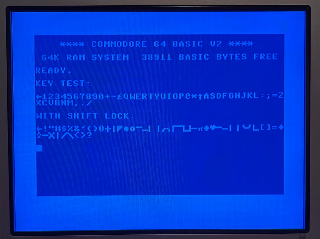
Connect and use the keyboard in normal Commodore 64 boot-up operation (blue screen)
Use a special keyboard test program to check all keys (including special keys)
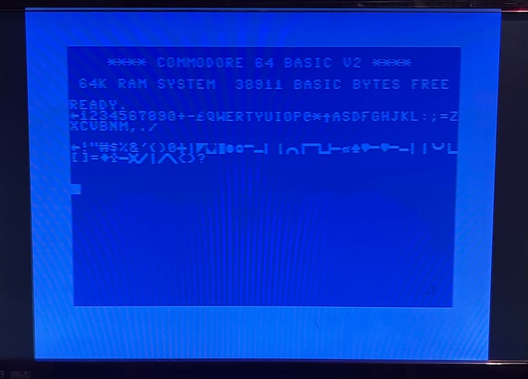
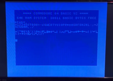
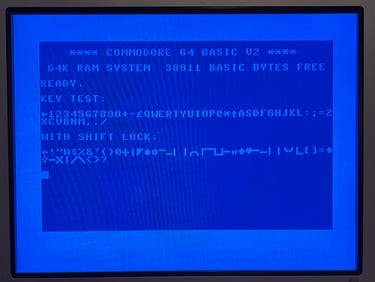
Testing the keyboard in normal Commodore 64 boot-up operation
Prerequisite: No joystick/paddle connected to joystick port #1 or #2 (can cause interference)
This is the simplest, but most important, test. The purpose of the test is to verify:
That the Commodore 64 boot to normal blue screen with a flashing prompt
That all the characters can be typed and are displayed correct on the screen
That the response time from pressing the keys to displayed on the screen is satisfactory
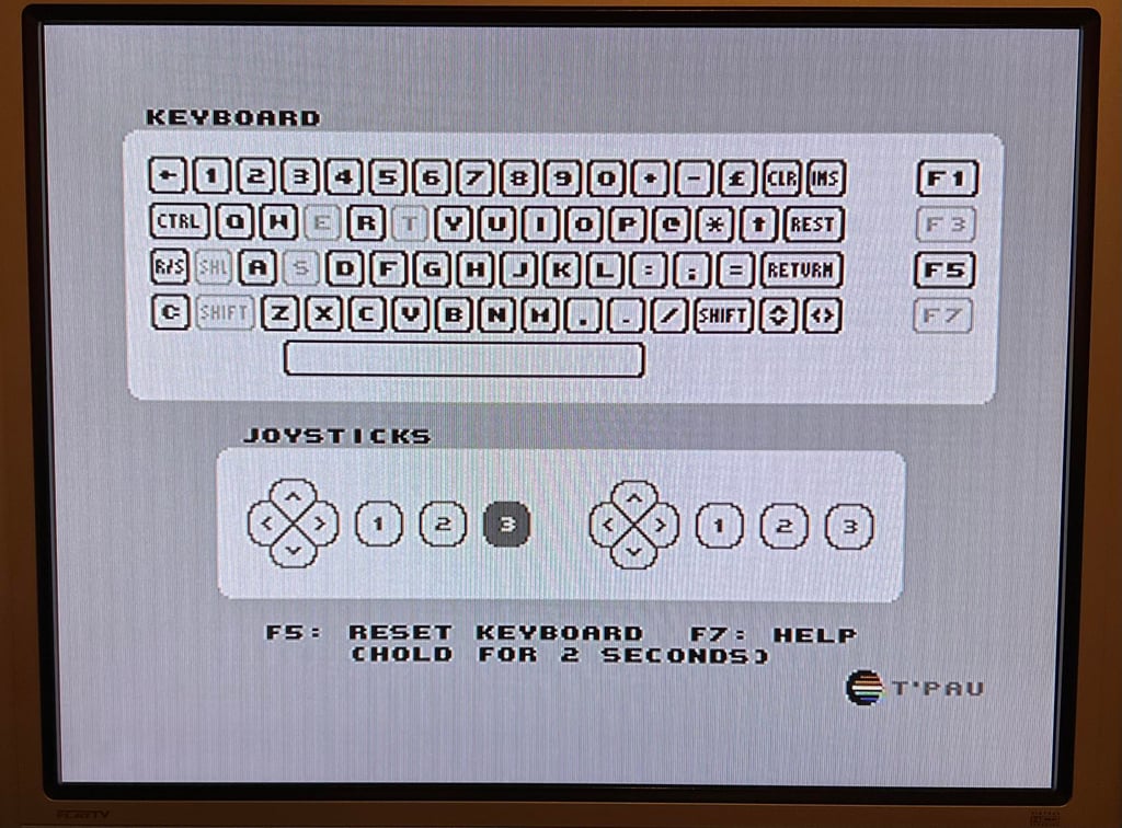
Testing the keyboard with special software
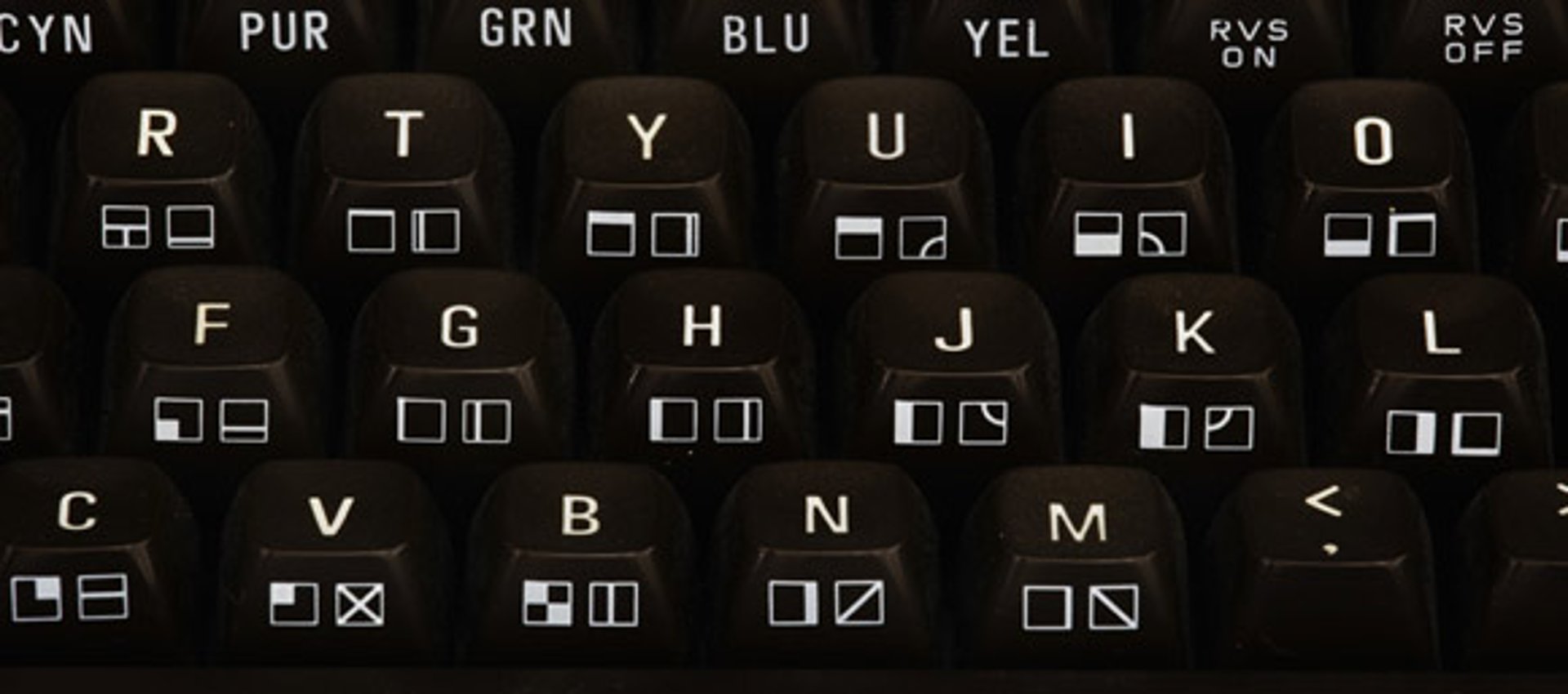
Knowing that the keyboard pass the basic testing a special testing software is recommended. The purpose of this test is to verify:
That all special keys such as "F1", "F3", "F5", "F7", "Commodore", "RUN/STOP" etc. register keypress with satisfactory response time
That the complete set of keys have been checked
A recommended software for testing the keyboard is Anykey. As can be seen in the picture below the keys which are being tested will light up on the screen for each keypress. Also, the software remembers which keys have been pressed (by showing them with a different colour) making it easy to verify that the complete set of keys have been checked.