

HOWTO
Desolder the RF-modulator
Introduction
There are occasions where you want to desolder the RF-modulator from the Commodore 64 mainboard. Maybe you want to replace the old electrolytic capacitors inside the RF-modulator, or it needs repair - or you want to replace the whole RF-modulator with modern replacements.
Alas, removing the RF-modulator from the mainboard is not trivial. Not that it is complicated in any way, but there is a good chance that you either break parts inside the RF-modulator or on the mainboard if you are not careful. During my years of repair I have found my way of removing these and I would like to share this with the hope that someone can use it and save another RF-modulator and Commodore 64.
Required tools:
Soldering iron
Desoldering gun
Hot air gun
Solder
Pliers
Thin flat screwdriver (optional: chip lifter)
Background
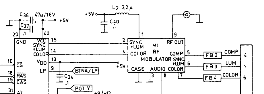

The RF-modulator is seen as a "black box" from both a Commodore 64 schematics point of view and a physical point of view. As seen from the schematics below there are eight input/outputs connected to the RF-modulator. Analog video from the VIC-II and analog audio from the SID are combined within the RF-modulator. Analog COMP, LUM and COLOR video and analog audio is output to CN5 and a combined video/audio RF-signal is output on the RF-connector.
Commodore used 3rd party vendors for the RF-modulator e.g. from Mitsumi. The whole RF-modulator come as a complete module - which was soldered onto the mainboard. Eight input/output connector pins from the RF-modulator are put through eight holes in the mainboard and four large ground pins from the casing are also put through holes in the mainboard. All eight plus four pins are soldered to mainboard, and to make sure the RF-modulator never can leave four small metal arms are bent in place to lock it to the mainboard.
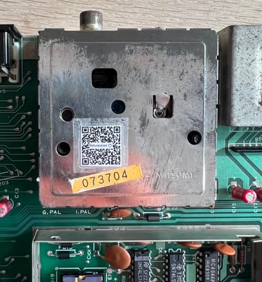
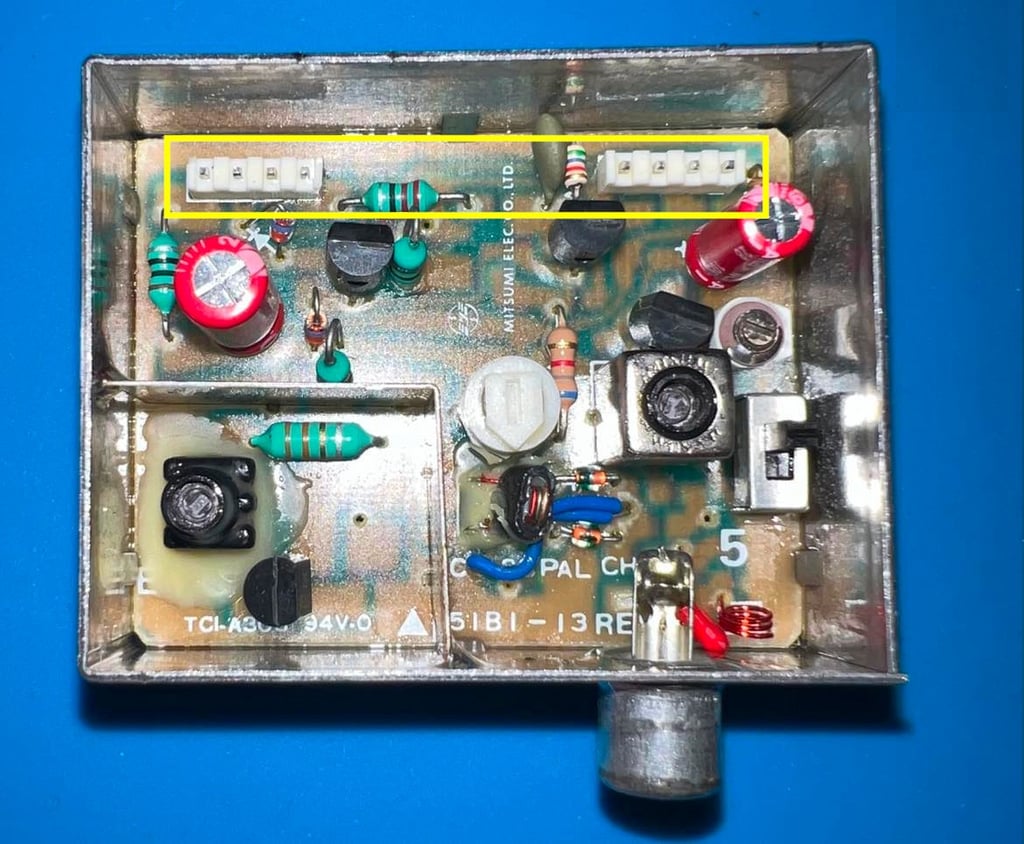
The picture below shows a typical RF-modulator from Mitsumi. Soldered to the mainboard as a complete standalone module.

In the picture below the following is shown:
Yellow squares: four twisted metal tabs locking the RF-modulator casing to the mainboard
Red squares: four large ground connectors soldered to the mainboard
Blue square: eight connector pins from the RF-modulator which are soldered to the mainboard
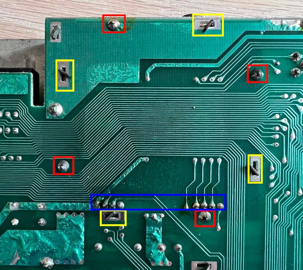
So it is easy to understand that this RF-modulator module has no plan of moving anywhere. The module is stuck to the mainboard with no more than 12 soldered points and four twisted metal tabs.
Desoldering the RF-modulator
In this chapter I will try to describe the principles and steps I use to desolder the RF-modulator. The most important principle - or advice - is to be patient. If you are in a hurry and rush the desoldering chances are that pads or traces will rip - either on the Commodore 64 mainboard or inside the RF-modulator. So, be calm and carry on.
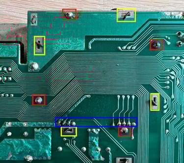
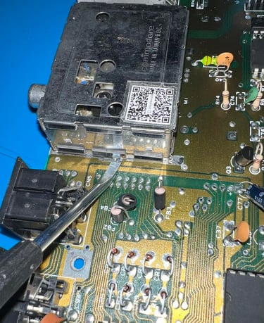
STEP #1 - Bending the metal tabs
This is an easy task, but important. Use a needle plier to carefully align the metal tabs so they are free to leave the square holes. The picture below shows an example of how the metal tabs should be aligned.

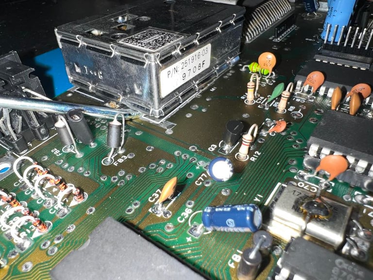
STEP #2 - Replenish the solder
All the four ground pins and the eight input/output connector pins are replenished with new solder. The addition of new solder will make the desoldering process easier. Note that the ground connector pins are quite large so the soldering iron temperature might be set to a higher temperature (e.g. 420 degrees Celcius).
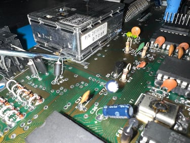
STEP #3 - Desolder the ground pins
To desolder the ground pins I use both the soldering iron - and the desoldering gun - at the same time. I place the soldering iron on side side of the solder blob and the desoldering gun on the other side. I´ve found that this method is both the most efficient and gives the best result. See picture below.
Step #2 and #3 sometimes need to be repeated to get all (or most of) the solder removed. The holes should look like the picture below. It is very hard to get all the solder completely removed, but with some patience and repeating step #2 and #3 most will be gone.

STEP #4 - Desolder the eight connector pins
This is the step you want to reduce the temperature of the desoldering gun - normally around 390 degrees Celcius should be more than enough. Carefully one pin at the time is desoldered. Quite often it is necessary to repeat step #2 and #4 to get all (or most of) the solder removed. Note that sometimes it looks like traces are burned away - but fear not. Often it is only the coating over the trace which is gone and the connection is still good.
STEP #5 - Lifting the RF-modulator
Ok, this is the moment to go into zen-mode. This is the part you do not want to rush. If you lift the RF-modulator before all pins, tabs and connectors are sufficiently desoldered you risk damaging either the RF-modulator itself or the mainboard.
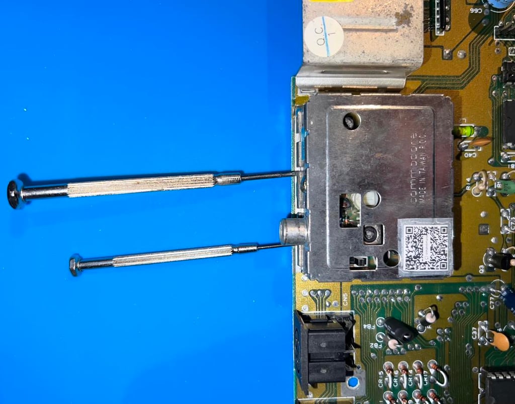
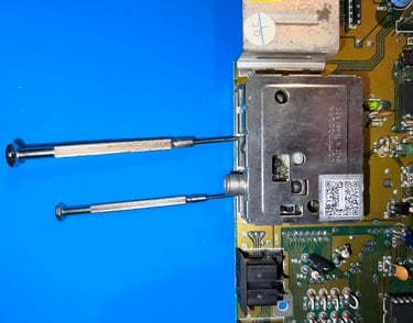
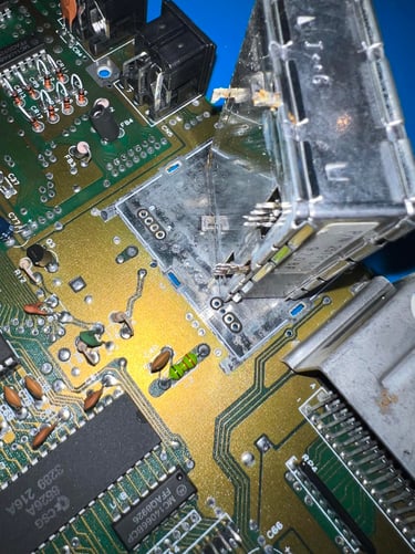
To start the process of lifting the RF-modulator from the mainboard I first find a small gap between the mainboard and the RF-modulator in the antenna output area. In this gap I gently pry the tip of a small screwdriver (or as in this picture two small screwdrivers).
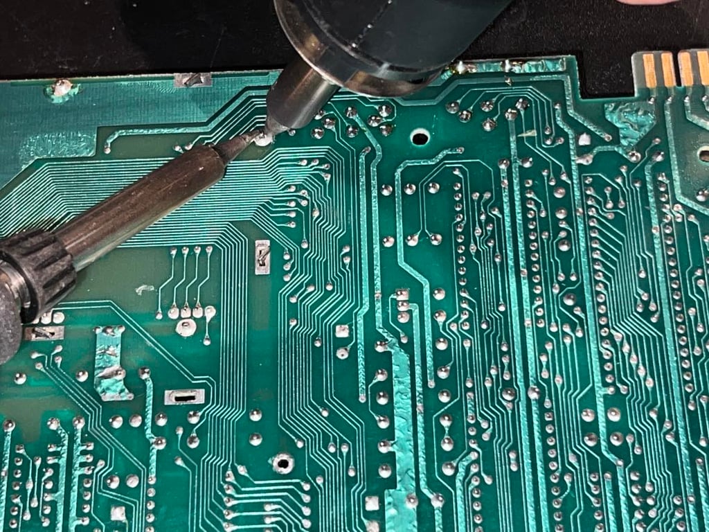
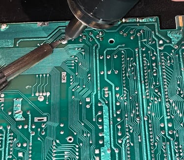
Now I start applying hot air around the soldering points on the backside of the PCB, while at the same time I carefully start lifting the RF-modulator with a screwdriver or a chip lifter. This process may take quite some time, but it is very important that you don´t rush it. I usually heat up some pins at the time and then simultaneously lift the RF-modulator casing in the same area. Below are some example pictures from this process where the left hand side of the RF-modulator is lifted. Tip: ask someone to help you heat the backside of the PCB with hot air while you lift the RF-modulator on the frontside (or grow a couple of extra arms).

After some wiggling and careful lifting the RF-modulator "pops" out.

Visual inspection
After the RF-modulator is removed it is good practice to check that "everything is ok" after the desoldering operation. There are two areas which should be inspected:
The eight pads on the mainboard PCB
The eight pins on the on RF-modulator
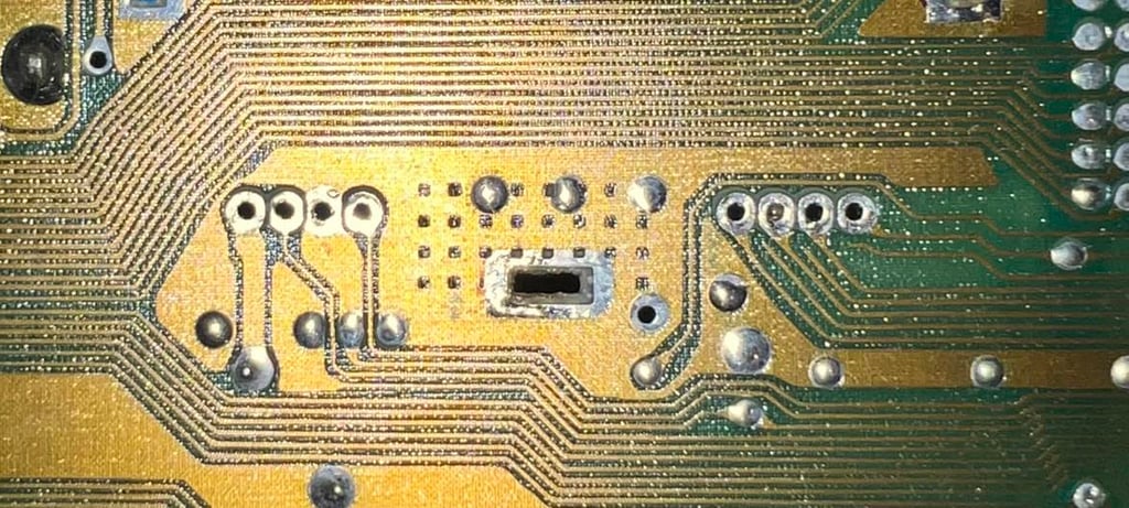
Checking the pads on the mainboard
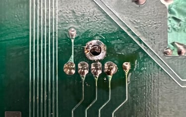
Carefully check the eight pads, both on the front and the back of the PCB, to make sure that they are not lifted from the PCB due to the desoldering. Clean them with some isopropanol on a Q-tip, but be careful so that the Q-tip doesn´t lift the pads. The pads should stay solid on the PCB after this cleaning. Note that there are some differences between the Commodore 64 mainboards. Some versions have traces on the top of the mainboard, and some have traces only on the backside. The pads can also be cleaned with a glass fibre pen, but I don´t think this is strictly necessary (but then they will look shiny).

Checking the pins on the RF-modulator
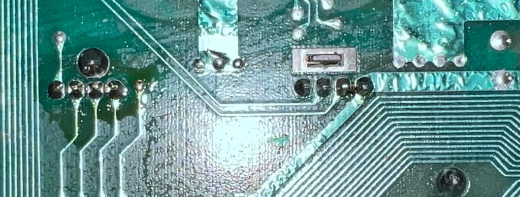
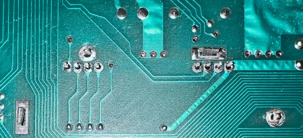
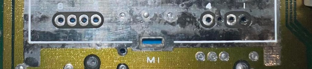
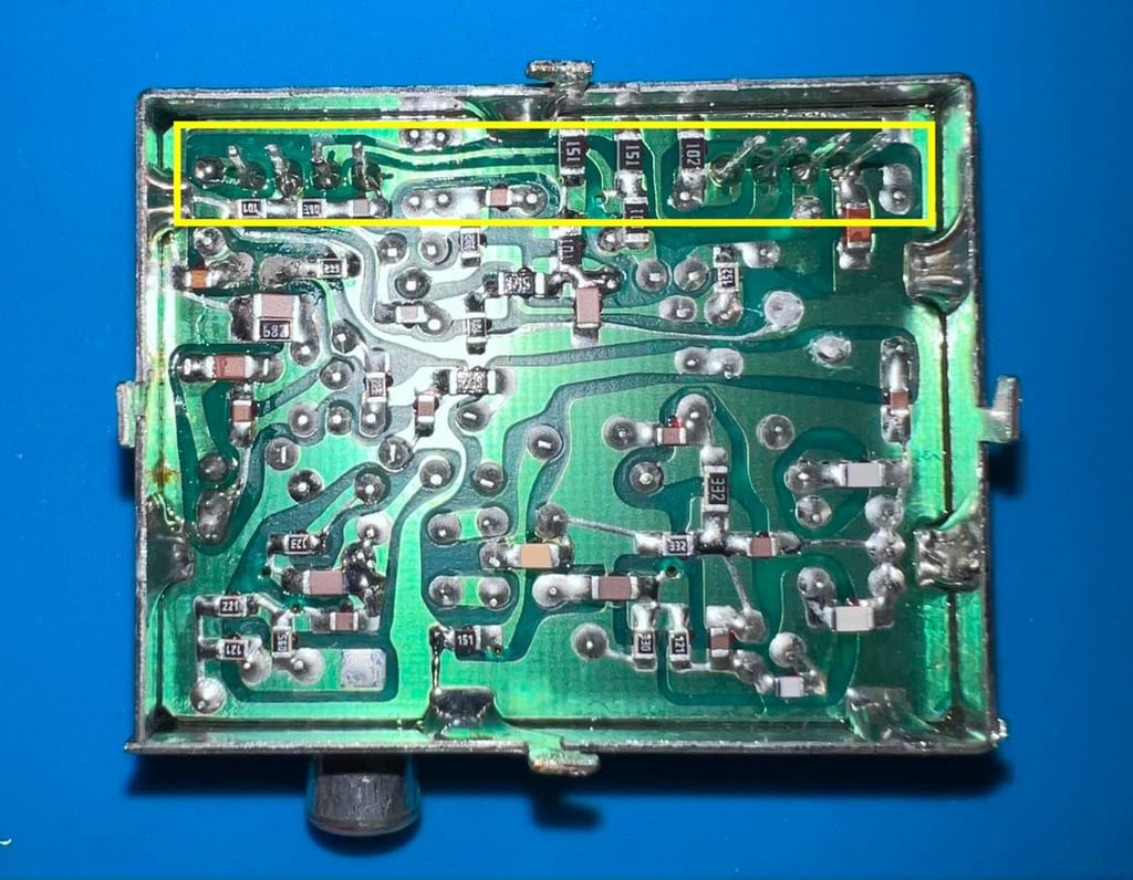
The eight pins on the RF-modulator should be straight and all have the same length - this would mean that they haven´t been "dragged" out of the socket on the PCB. My way of checking that the pins are ok after desoldering is to first check the topside of the PCB in the RF-modulator. If I can see the top of the pins protruding the socket I know that they have not been pulled out of their position. In the picture below you can see all the eight pins protruding the two sockets (yellow square) - indicating that they are all ok.

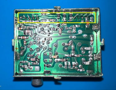
Finally, the eight pins are checked from the backside of the RF-modulator. They should look straight and without any visual damage. See picture below (yellow square).