

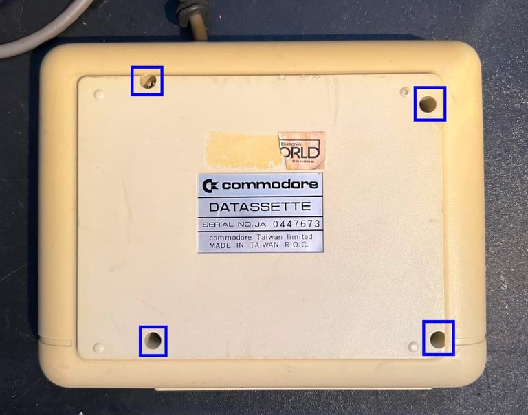
1530 (C2N)
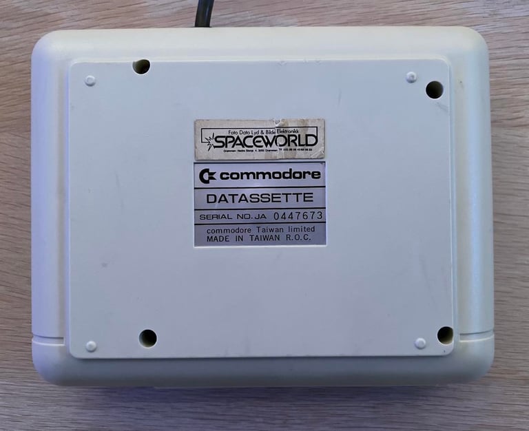
Ser. No. 0447673
Starting point
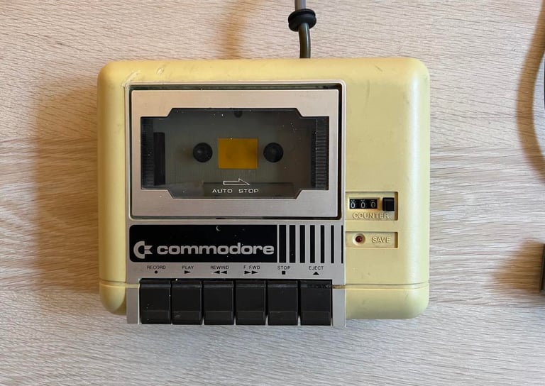
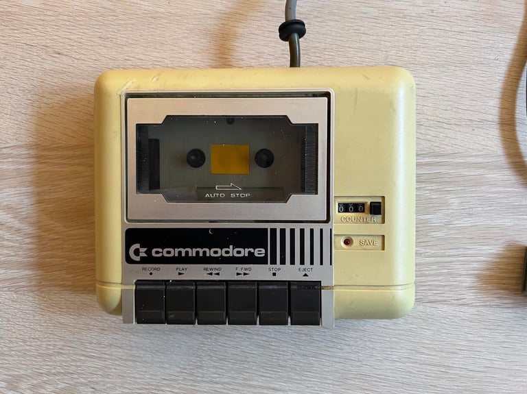
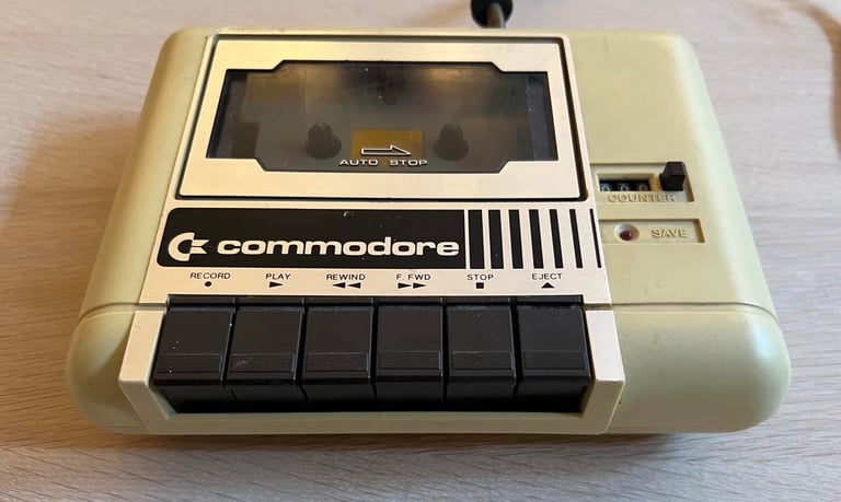
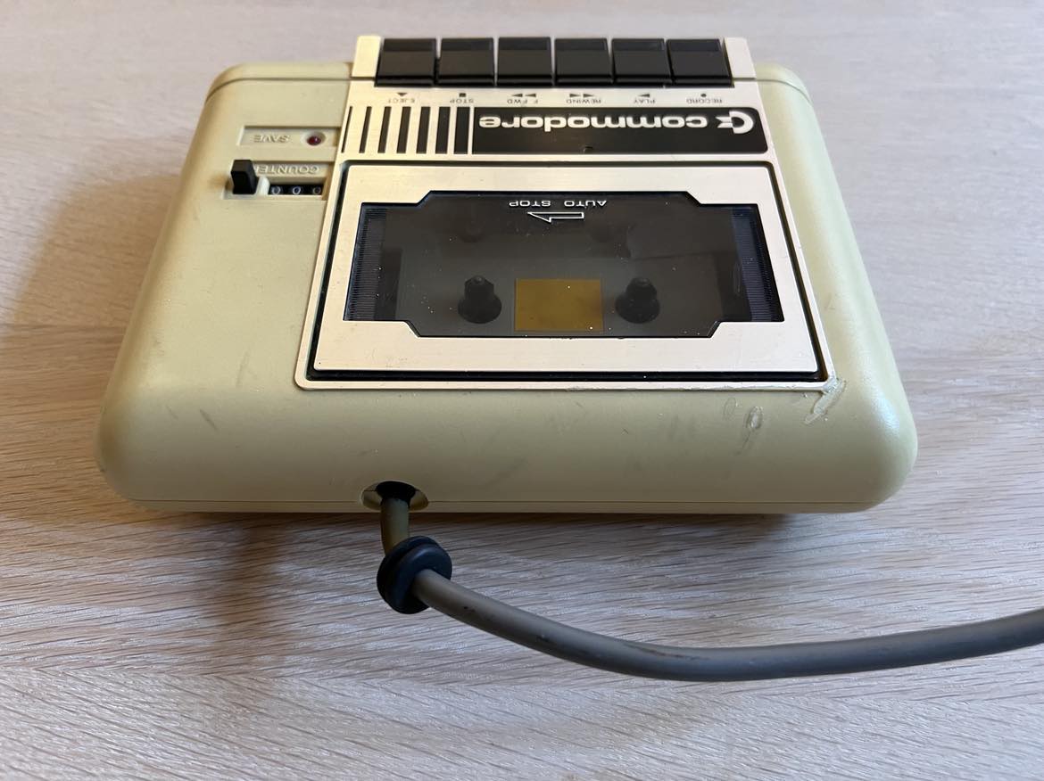
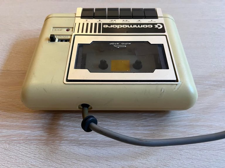
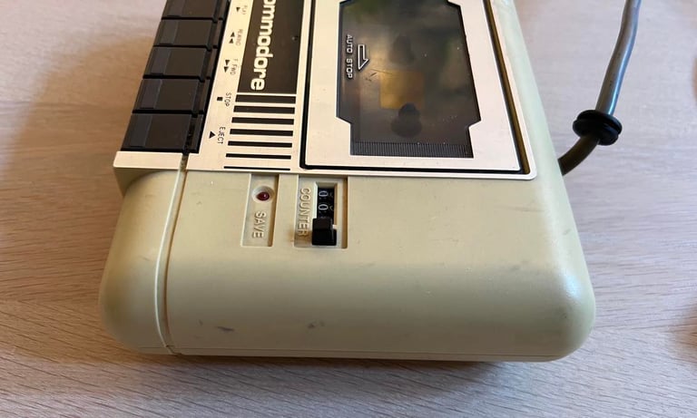
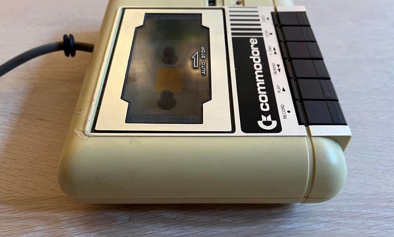
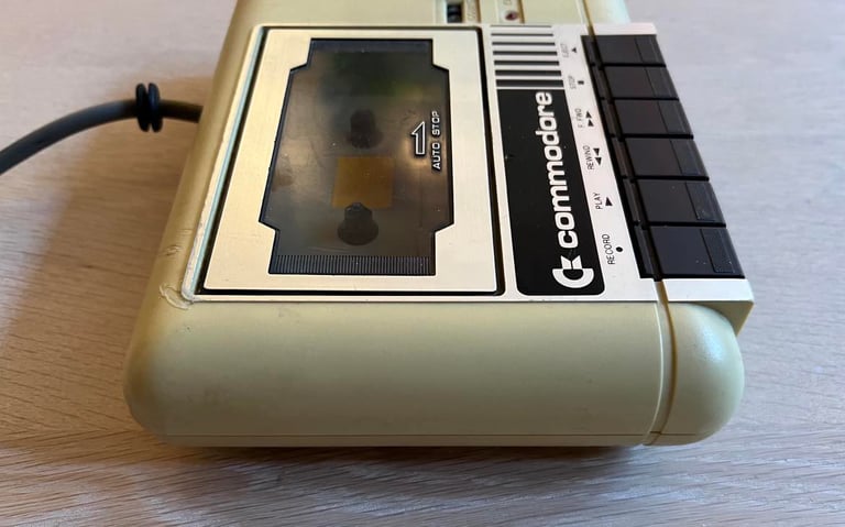
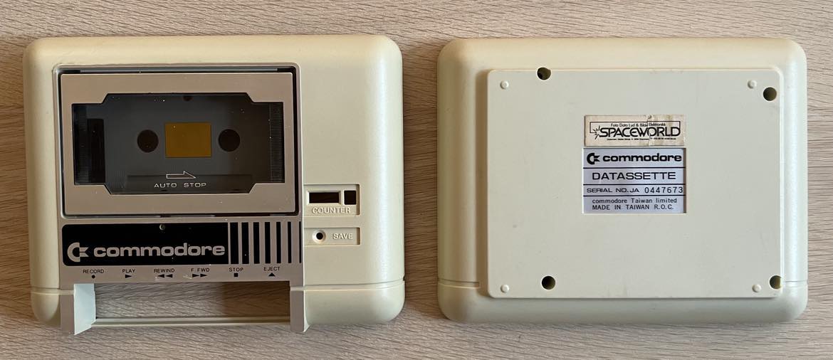
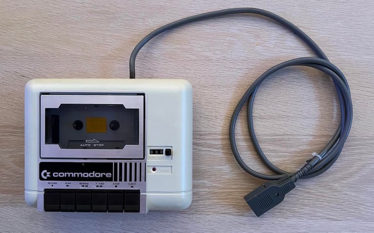
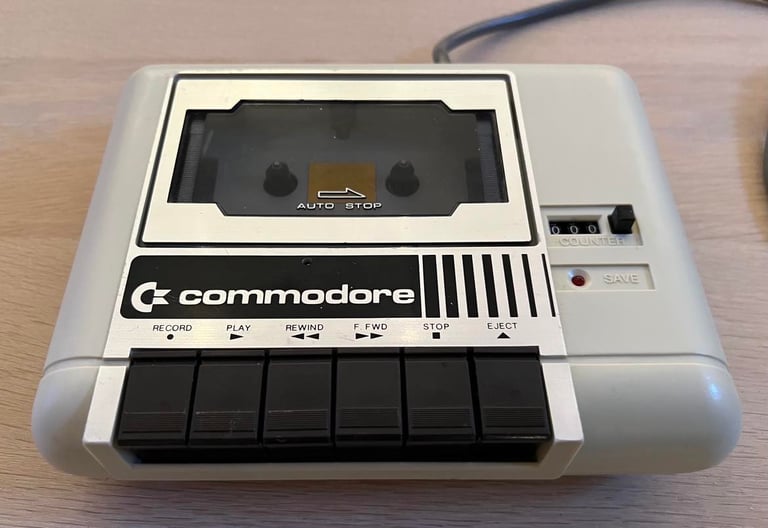
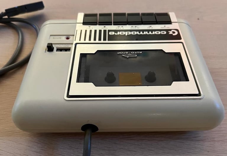
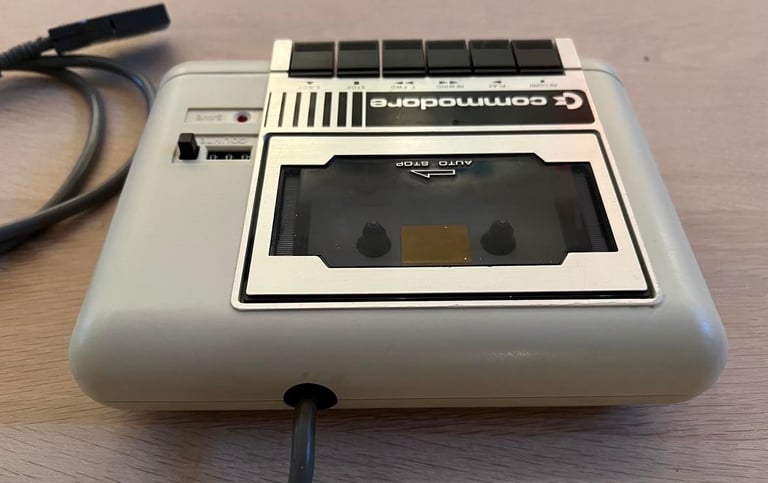
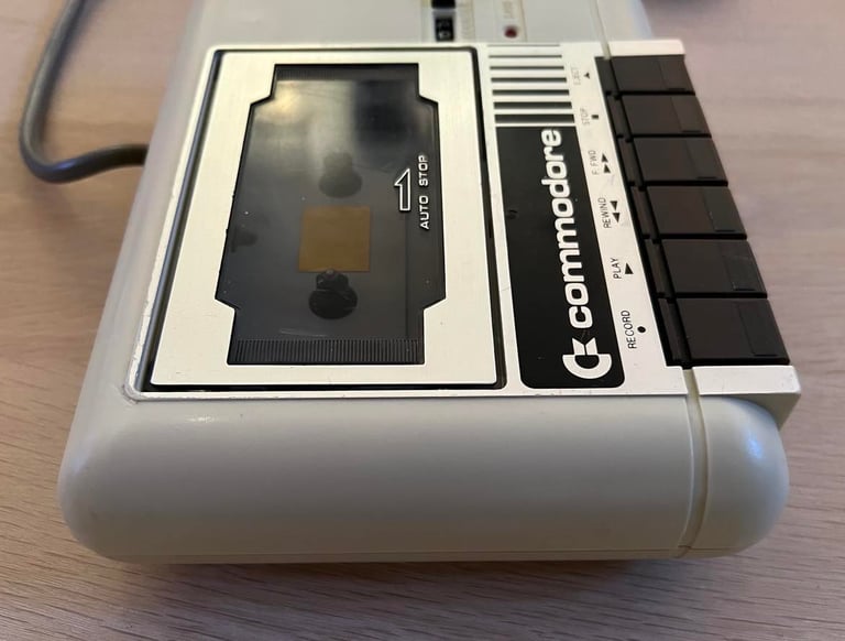
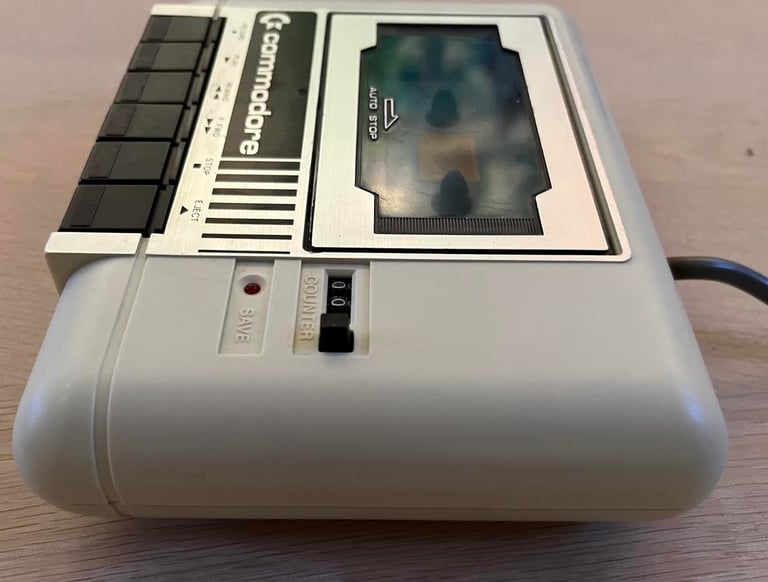
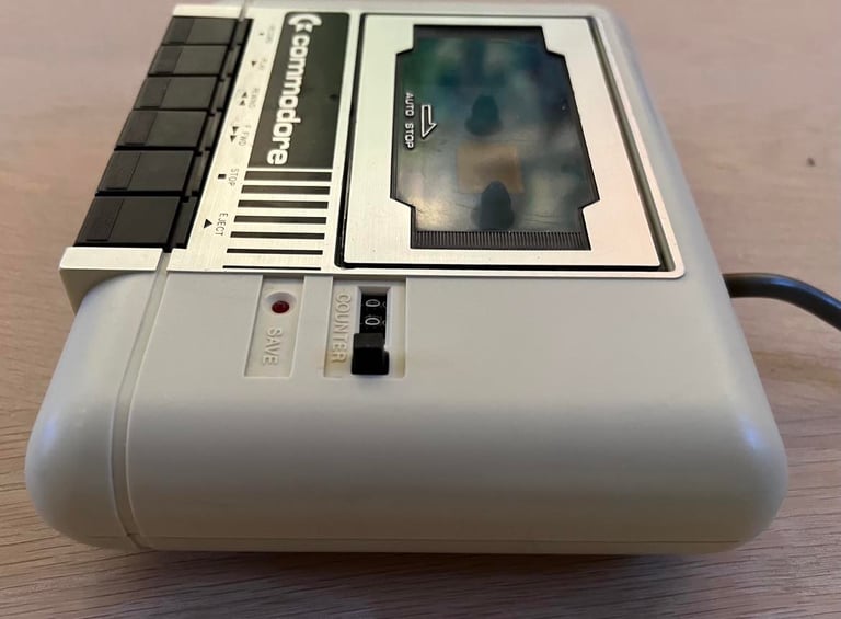
Let´s start with the good part first: it looks to be intact without no major damage. But it´s yellowed (the pictures don´t do it justice - it is worse), some cable marks, dirty and the strain relief is out of the cover. I have no idea if this datasette even works at the moment. Nevertheless, I think I can manage to achieve a good end result after refurbishment, but there will be quite some work with this one.
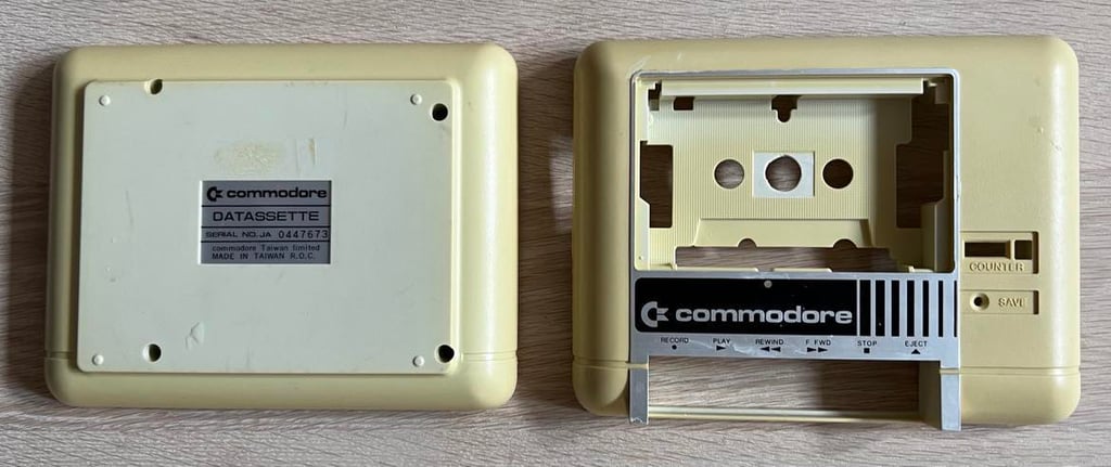
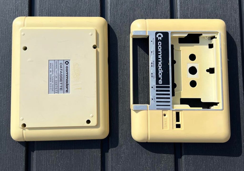
Below is a gallery of the datasette before refurbishment.
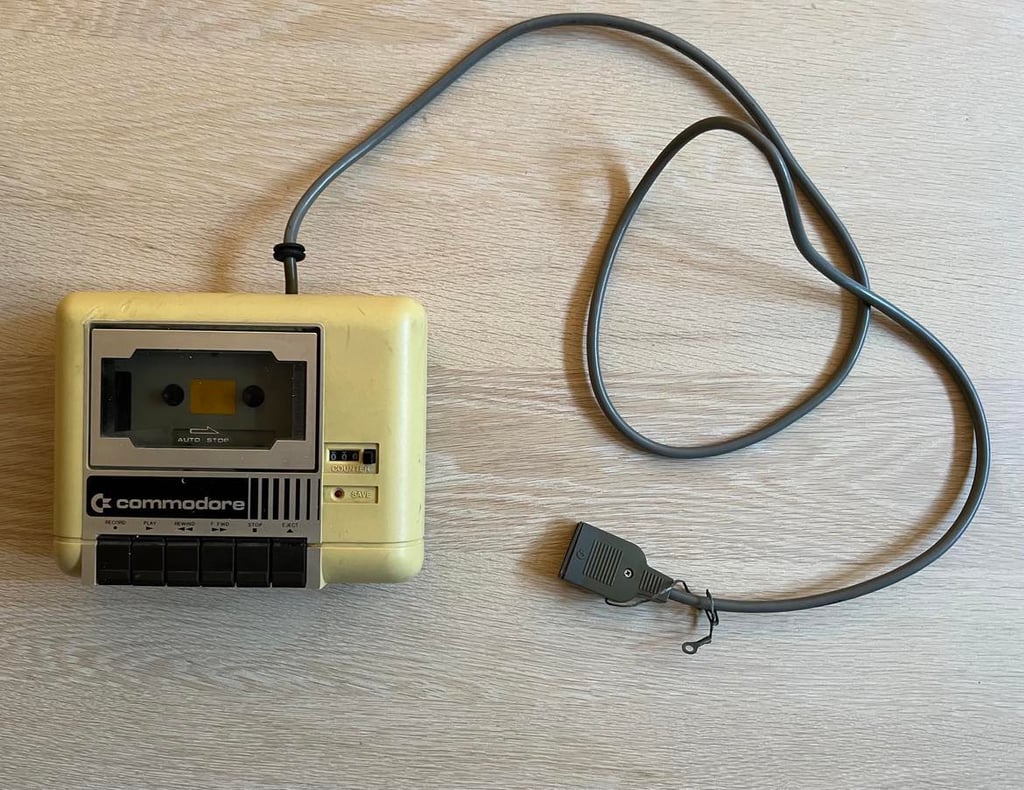
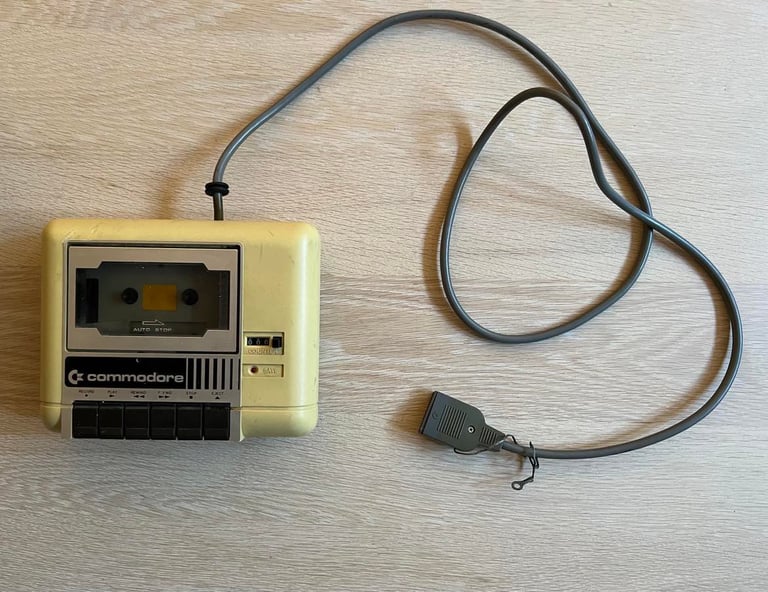
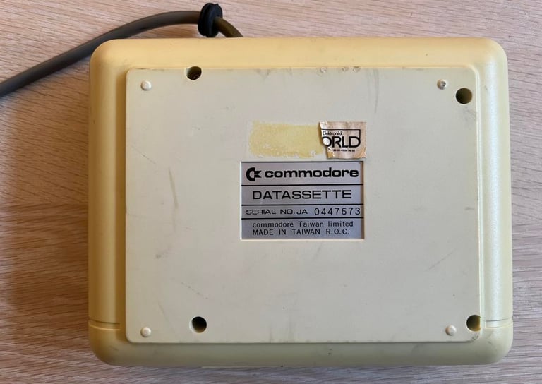
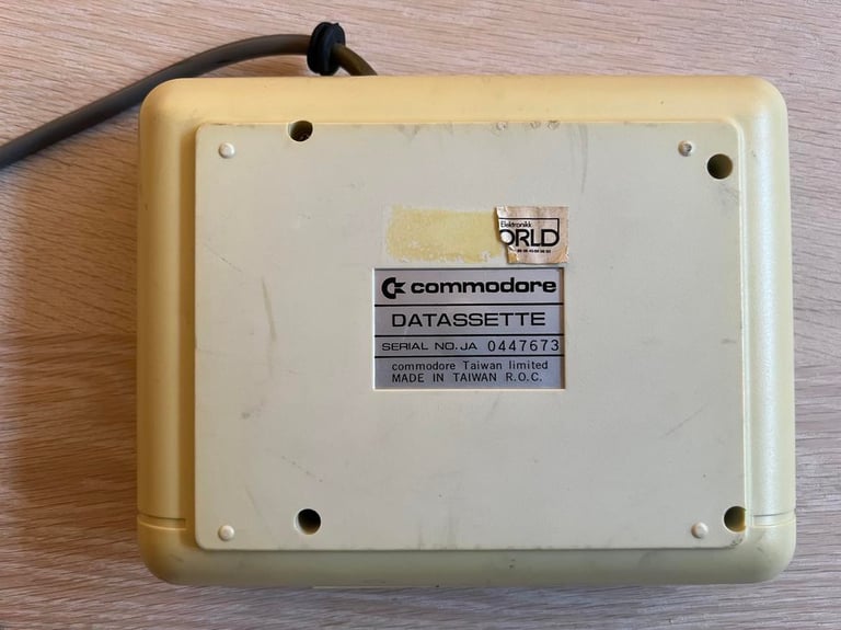

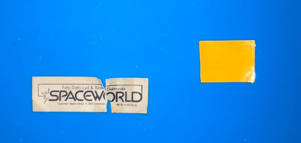
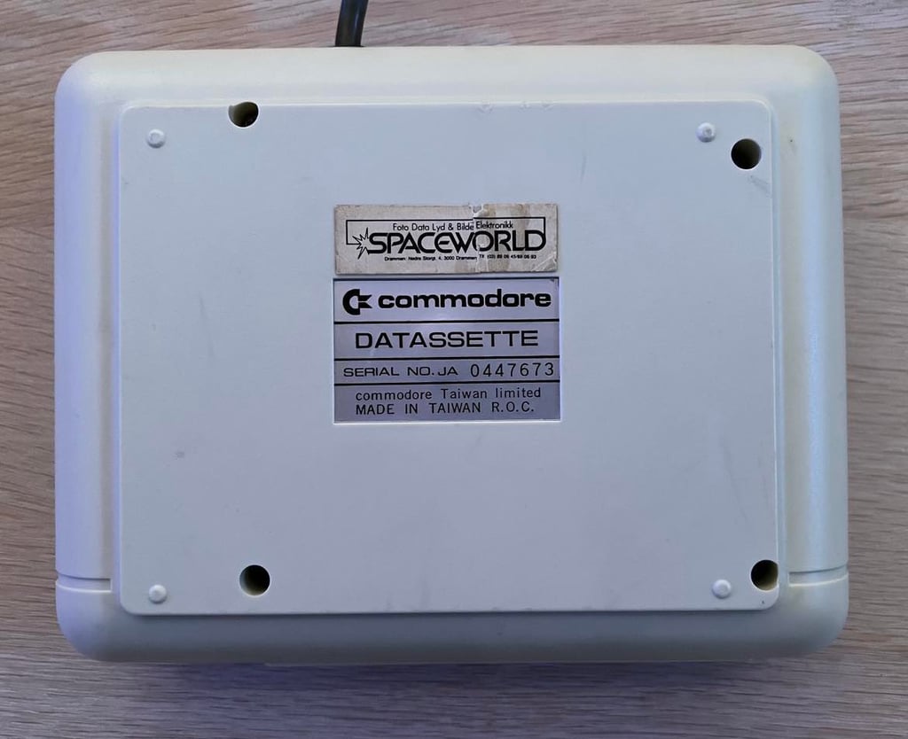
Notice the litte torn sticker at the back "orld". This is an old label from the Norwegian dealer "Spaceworld". Luckily, I also have the other half of the label - hopefully I can repair the sticker also!
Refurbishment plan
To refurbish this 1530 datasette the plan is to do this trough the following steps:
- Clean and remove stains from exterior casing
- Clean the interior mechanics
- Check cable and replace strain relief
- Check PCB for corrosion and replace old electrolytic capacitors
- Replace motor- and counter belts
- Adjust head for optimal tape reading
- Verify datasette operation by testing
Note that several of these steps are done in parallell.
Exterior casing
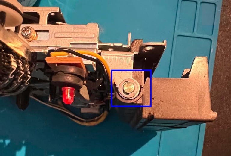
The 1530 casing consists of a top- and bottom cover. To disassemble these the four screws at the bottom are removed (blue squares).
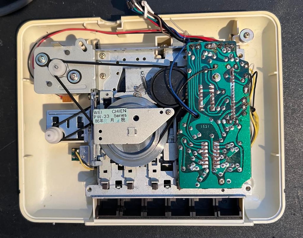
Removing the bottom cover reveals the interior of the datasette. And the interior looks surprisingly good! There is very little dirt inside, and almost no sign of corrosion on the metal chassis. This is not common - quite often the interior is a bit "rusty" after 40 years. So this was a pleasant surprise.

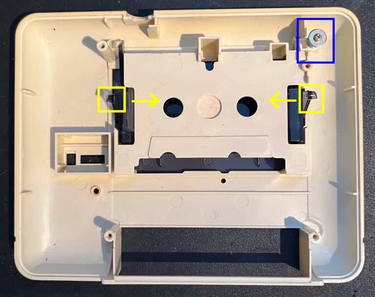
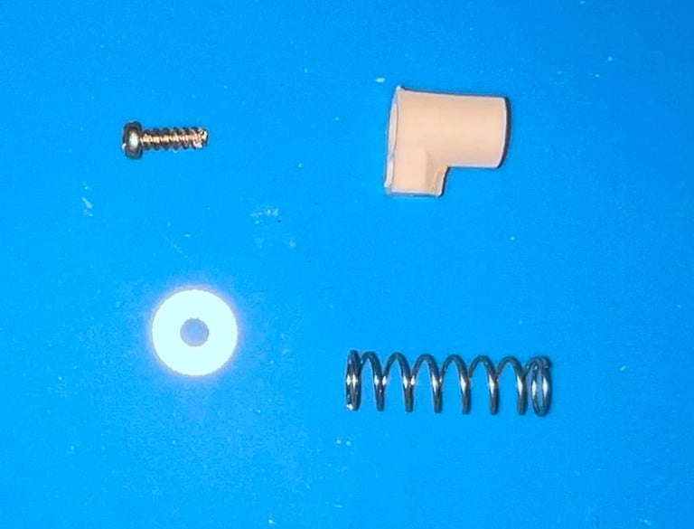
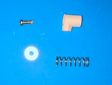
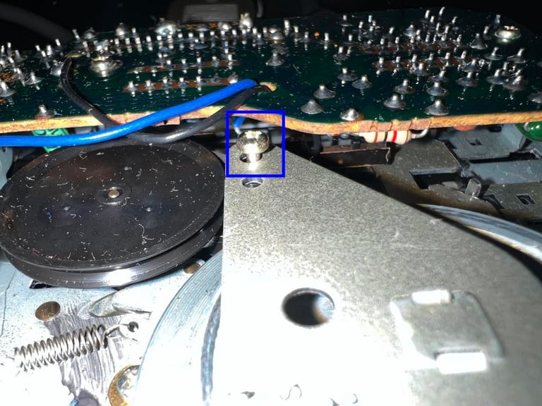
The interior mechanics is lifted out and the top cover is revealed. First, the screw, washer, spring and plastic "thingy" (blue square). Next step is to remove the tape lid. This is done by carefully pushing the two arms inwards (see yellow squares) and then push the lid out. It is important to be a bit careful since the plastic can be brittle.

There are two stickers that I remove before cleaning. Well, half of the "Spaceworld" sticker was already removed... The stickers are removed using a very thin and sharp knife.

The top- and cover is cleaned thoroughly. It is really - REALLY - dirty. And a lot of cable marks (almost looking like burn marks). The cable marks are removed with some wet P1000 sanding paper. The result is not perfect, but I am quite happy with it. So now the top- and bottom cover is clean and sanded. But it is very yellowed so to make it a bit brighter the covers are placed in the Stavanger sunlight for several days (estimate about 8 days in total). I think that sunbrighting is not as intrusive as retrobrighting - quite the same result - but with less chemicals (with the price of longer waiting).


Summertime!
While the covers are sunbathing the six keys are removed. This is done by first removing the small metal clip (blue square) and then pulling the shaft out carefully.

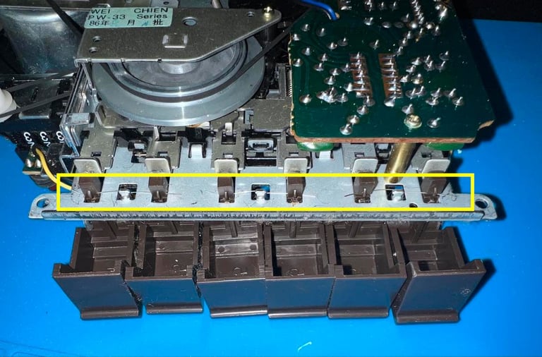
From the backside of the interior the three small springs are carefully removed using a pair of precision tweezers (yellow area). When the springs are removed all the six keys are pulled out of the interior chassis.

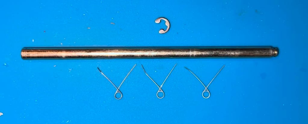
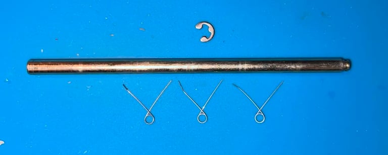
Below is a picture of the newly removed parts; the metal clip, shaft and the 3 x springs. Note that the small springs are very easy to loose so it is a good idea to put them in a small plastic bag.
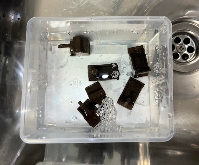
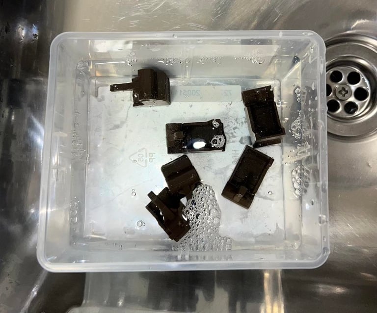
The keys are placed in mild soap water for a few hours. There are some markings from the cable (like small burn marks), but I choose not to do anything with it. Sanding will probably make it look worse.
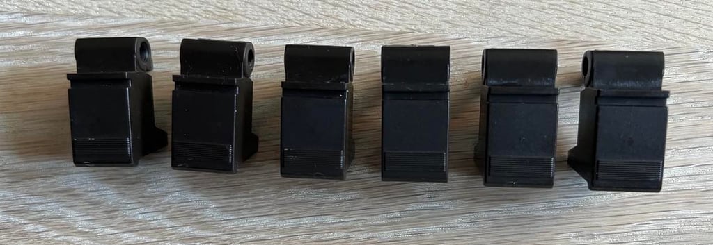

I am quite happy with the result of sunbrighting and cleaning. There are still some marks from the cable, but it looks way better than before the refurbishment. Also the "Spaceworld" sticker is repaired with some double sided tape.

Interior mechanics
When this is done the metal bracket is tilted/lifted slightly - just enough so that the belt can be pulled away from the bracket. With the belt out of the way the two screws are screwed back to original position.
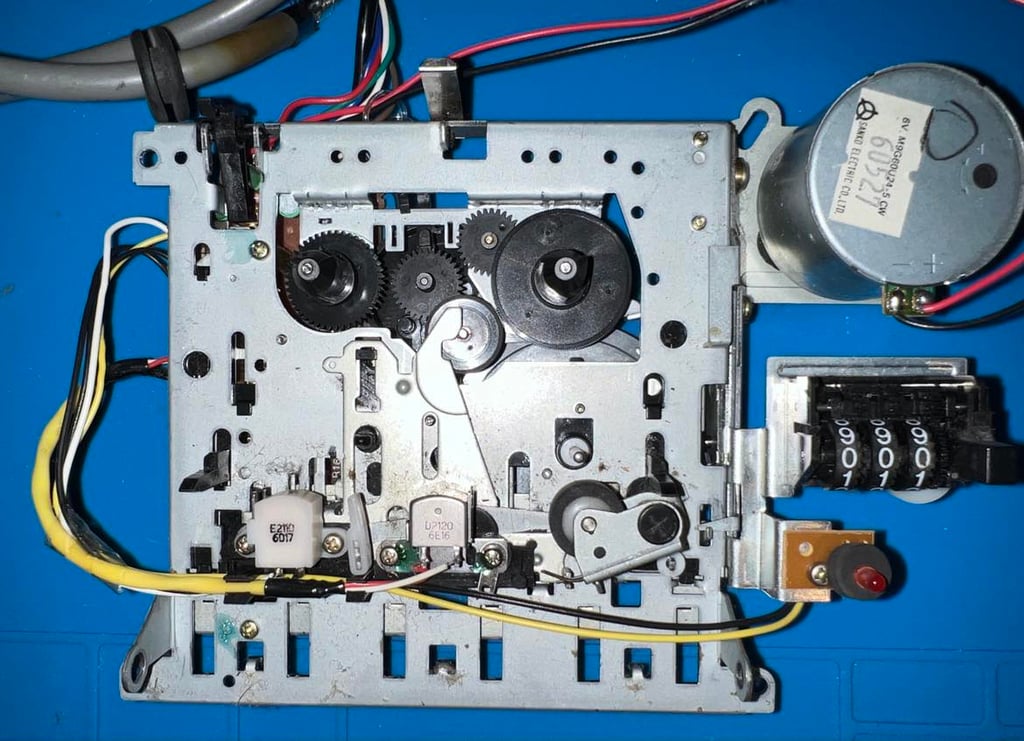
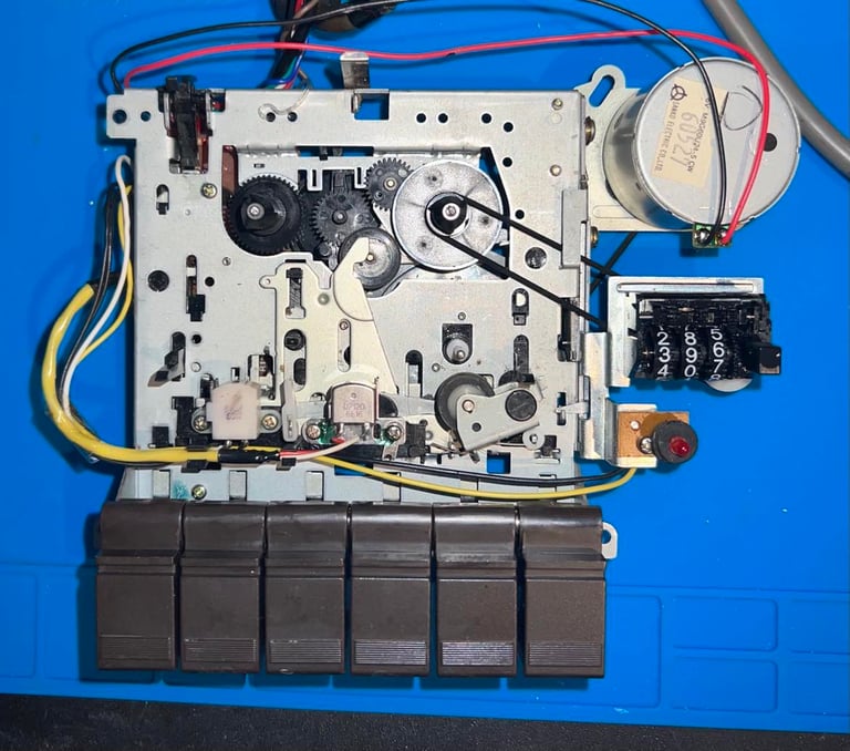
The interior of this datasette is impressively clean after almost 40 years. I have refurbished quite a few datasettes, but this is probably the most clean I have seen before refurbishing. Has it been cleaned before? Maybe, but I do not think so. Opening these datasettes to clean the interior is not something anyone used to do back in the days.
Nevertheless, I will clean it properly, replace the belts and the electrolytic capacitors.

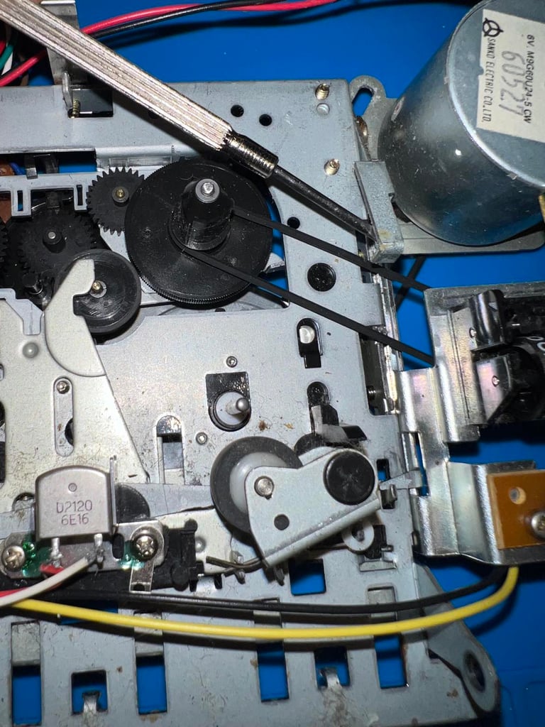
First, the two belts in the datasette are removed. These will be replaced at a later stage. To remove the counter belt is just to lift the metal rod slightly and pull the belt away. See picture below.
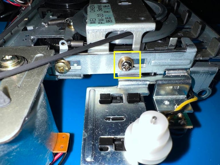
Removing the motor belt is not hard - if you only remove the screws which are strictly required. If you remove too much (or too many) it can be painful to reassemble the parts. The first step is to completely remove the small screw on the side (yellow square). Then the screw holding the metal plate (over the flywheel) is partly removed (blue square).


To clean the back of the interior throughly the PCB is removed. This is done by first removing the two screws (yellow squares) completely.
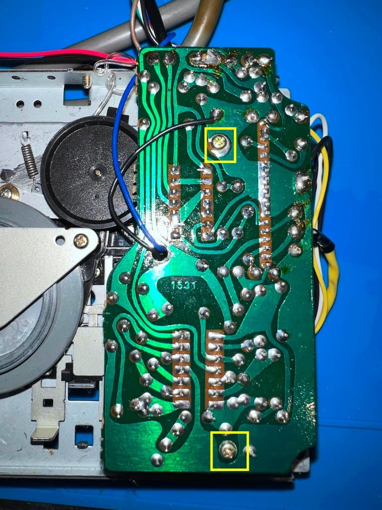

Then the PCB is lifted slightly and the leaf switch is exposed. This leaf switch is preventing the PCB from being lifted from the interior mechanics. So in order to remove the PCB the screw holding the leaf switch is removed (yellow square).
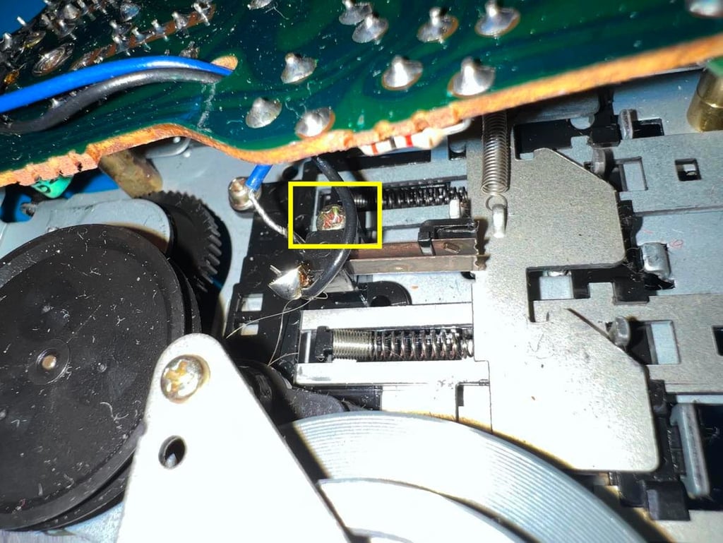

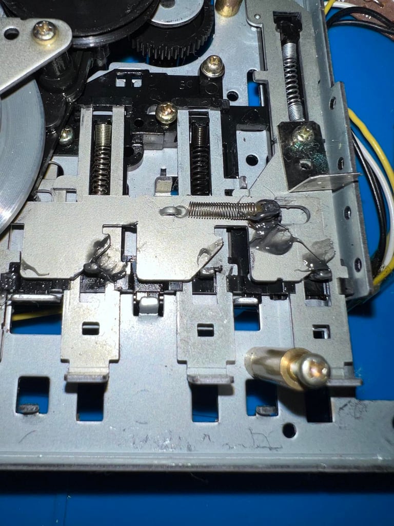
Both the front and back of the interior are cleaned properly with isopropanol on a Q-tips. Also, on the back some of the moving parts are lubricated with some MoS2 grease. See picture below for where the grease is applied.

The final cleaning stage is actually done after the belts and the electrolytic capacitors are replaced. The reason for this is that now I can clean the rotating parts while they are in fact rotating. I connect the datasette to a Commodore 64 and then press keys such as PLAY/REW/FF to get the gears to rotate. And when the rotate I clean them carefully with isopropanol and Q-tip.
This is very efficient when cleaning the capstan and the pinch roller. A couple of videos on how I do this are shown below (from another refurbishment - but I use the same principles).


Cleaning the capstan
Cleaning the pinch roller
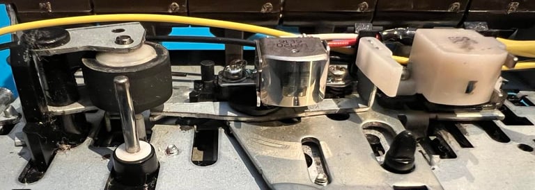
The erase head and the read/write (R/W) is the last thing to be cleaned. It is very important that these two are properly cleaned for the datasette to operate - it does not help if the R/W is aligned if its dirty. Below is a picture of the heads after cleaning,

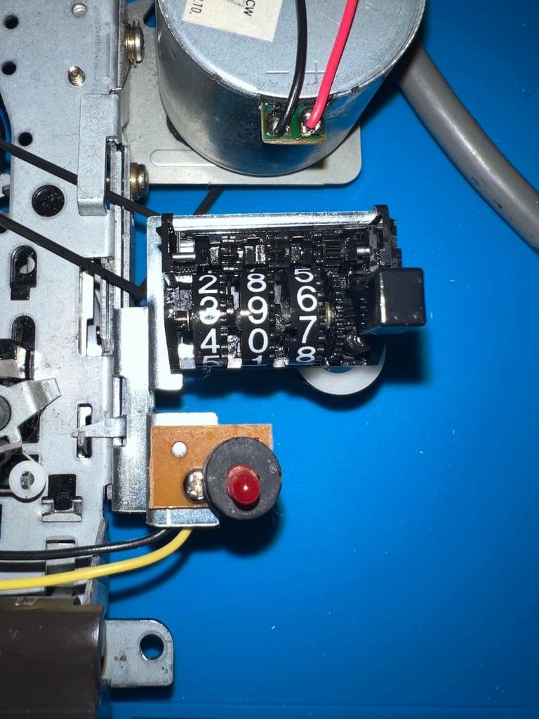
To make sure the counter still works after 40 years it is lubricated with some silicone spray while the datasette is running with PLAY/FF for a few minutes.
The front of the datasette interior after cleaning is shown below. I am quite happy about the result. I think this will be a very nice datasette in the end!

Cable
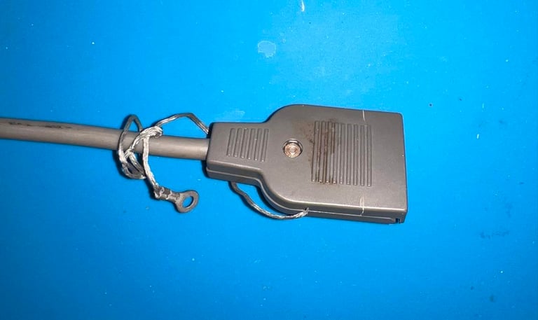
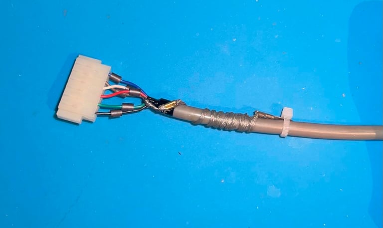
The cable looks to be intact, but the connector casing is both dirty and seems to have a small crack. The small crack doesn´t seem to be very important in regards of how the connector would work. Is it only the plastic casing - the "real" connector is hidden inside the plastic cover - and this connector looks to be in good condition.
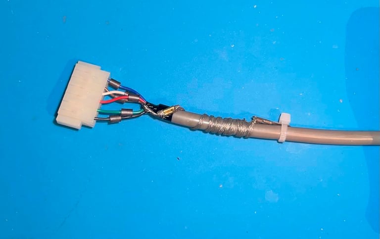
When the connector cover is removed the inside is revealed. And as mentioned already it looks to be undamaged and in good condition. All the metal pins inside the connector are checked and cleaned with some contact cleaner. Also, the ground wire is twisted around the cable and fastened. The ground wire is not used in the 1530 C2N datasette for the Commodore 64. This is only a legacy from the earlier PET days. The only thing that the ground wire can do is to enter the user port and short circuit... which we don´t want (?)
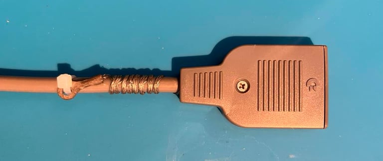
The connector cover is also sunbrighted for a few days. Unfortunately, I forgot to picture how yellowed the frontside was, but the end result is nonetheless quite good I think. As previously mentioned there is a small crack in the connector casing, but I do not see this as anything else than a cosmetic issue. The connector itself is in good working condition.

PCB and electrolytic capacitors
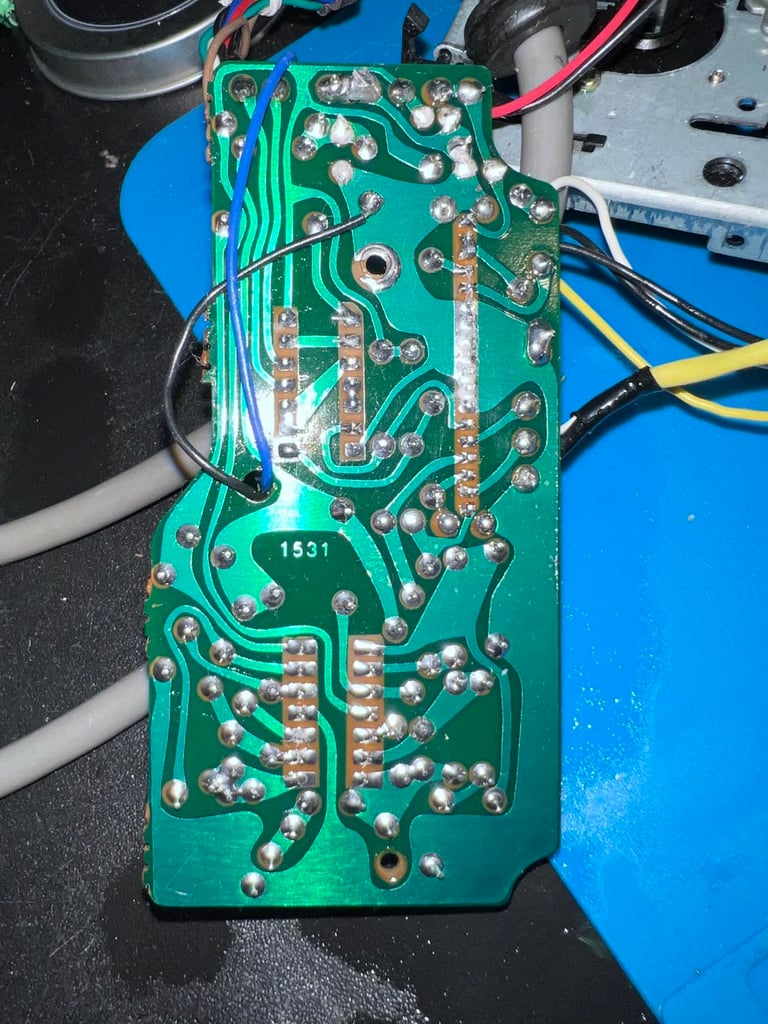
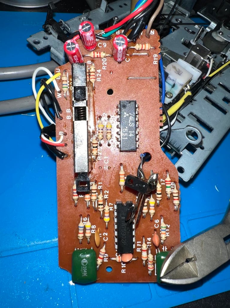
The PCB is a "1531" version and is quite "sticky", but I think is due to some old flux residue. So the PCB is cleaned thoroughly with isopropanol. I can not see any sign of corrosion or any other damage.
There are four 47 uF [16 V] electrolytic capacitors on this PCB. All of them are replaced with new capacitors from Wurth Electronics.

Replacing the belts
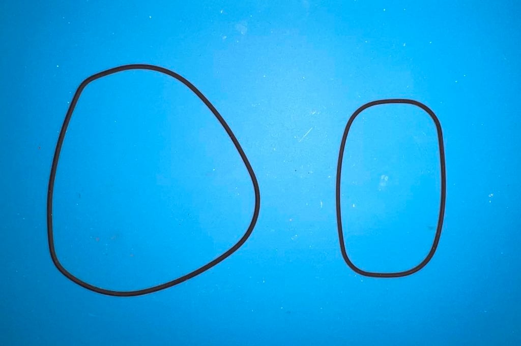
There are two belts in the datasette: one for the counter and for for the motor. The former is not strictly necessary to change, but the latter is if you want the datasette to operate as it should. These belt both loose their flexibility, elasticity and shape after sitting inside the datasette for almost 40 years. Below is a picture of the old belts - and as can be seen they are severely deformed.

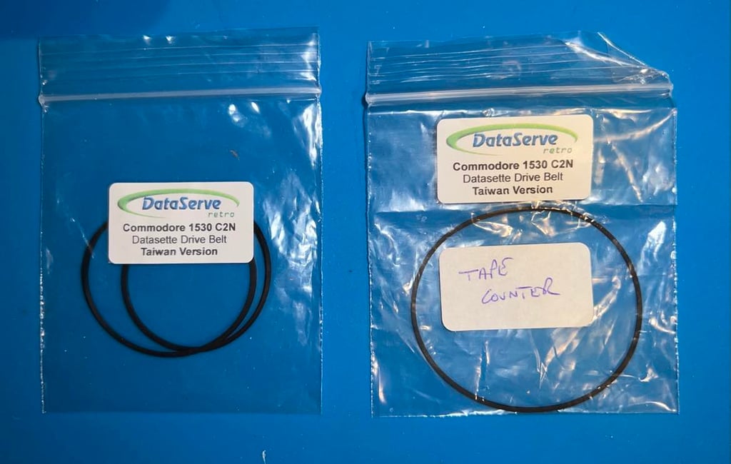
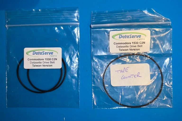
New belts are ordered from DataServe retro for both the counter- and the motor belt. Note that this datasette use the "Taiwain" version of the belts (and not the "Japan" version").
R/W head alignment
In addition to replacing the belts it is crucial to check the read/write (R/W) head alignment and if necessary adjust it. Otherwise the datasette can´t load our beloved tapes without the notorious "?LOAD ERROR" or simply just fails loading.
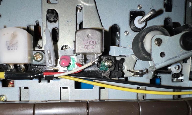
A detailed article about how I align the R/W head can be found here. As seen in this article I use both an oscilloscope and C64 software to do this operation in two stages; in the first stage I solder on two wires after the 2nd OP-AMP stage, connect the oscilloscope to these wires and then adjust the R/W head until I find the maximum amplitude on the oscilloscope. Second stage I use cassette-azimuth software running on a Commodore 64 while loading games from tape. In this second stage I do not do any adjustments - I only validate that the adjustment done in the first stage is correct.
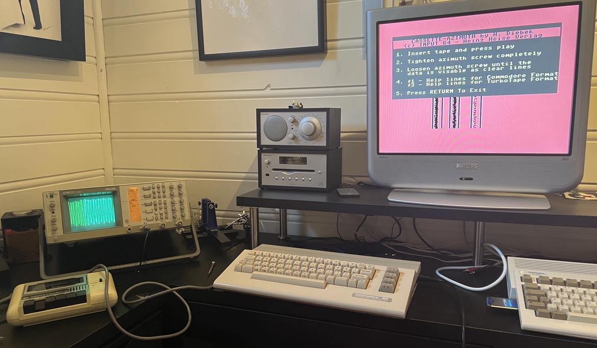
Stage 1 - Aligning the R/W head with the oscilloscope
Below is a picture from aligning the R/W with the oscilloscope. The oscilloscope is connected to the two wires soldered to the PCB as shown in the article. It is very important that the datasette is completely assembled when doing this alignment - with the tape lid and all four screws. If the datasette is aligned e.g. with the tape lid removed there is a significant risk that the R/W will be "misaligned" when the datasette is completely assembled.
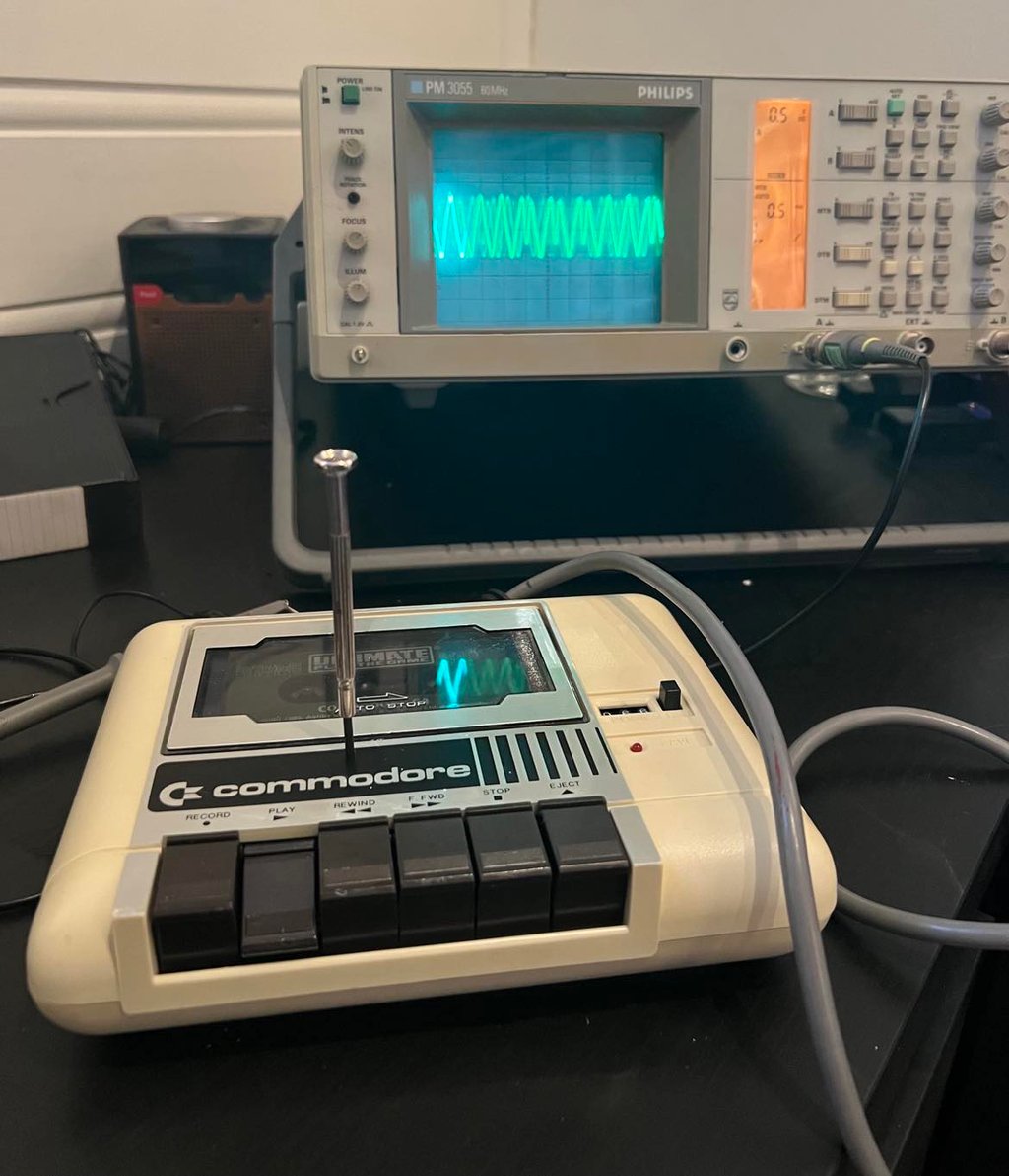

As can be seen from the picture above I use a small screwdriver to adjust the R/W head. I do this by first tighten the screw completely (clockwise), and then while the tape is loading slowly adjust the screw counter clockwise until the maximum amplitude is reached. What is maximum amplitude? Well, it depends - but my experience is that this amplitudes (for the "1" signal) is around 0.6-0.8 V at this 2nd OP-AMP stage. Note that you are looking for the maximum amplitude at this 2nd OP-AMP stage and not an exact voltage level (the signal is going to be converted from an analog to digital signal in the next to OP-AMP stages but is not dependent on an exact voltage level - but is dependent on having the maximum at the 2nd stage).
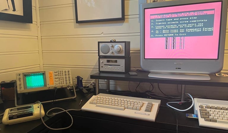
Stage 2 - Verification of the adjustment
To verify the adjustment with a second tool I use the cassette-azimuth software running on a Commodore 64. When the tape is loading there should appear three vertical bars on the screen. And the goal is that these three lines are as "solid" as possible. Note that these lines will never be completely solid, but the goal is that they are more or less straight vertical lines. If you have a misaligned R/W these lines will be scattered all over the screen.
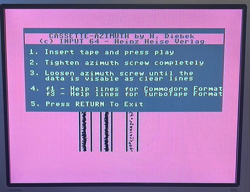
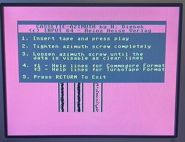
The picture above shows that all the three lines are looking good - they are as vertical lines as they can. This should imply that the datasette should be ready for operation. I run a few tapes just to make sure that everything looks good - and it does. The datasette should now be ready for the final testing.
To lock the R/W head in position it is good practice to add a drop of nail polish (of your favourite color). It is not a guarantee that the R/W will not move afterwards, but it will reduce the risk.

Testing
Playback
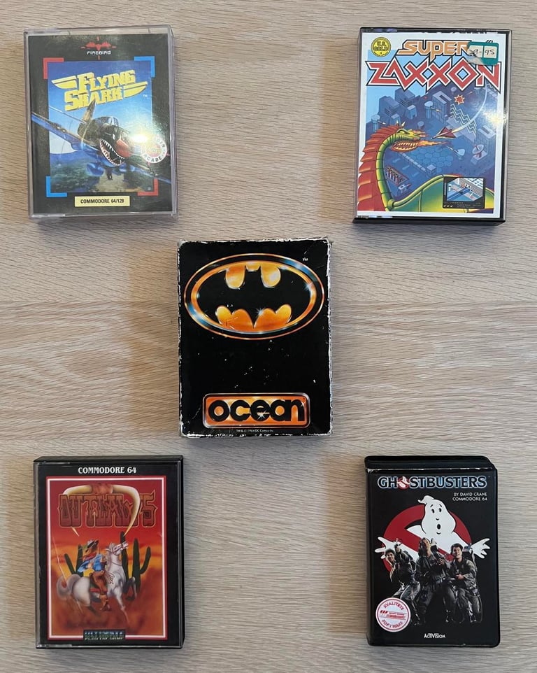
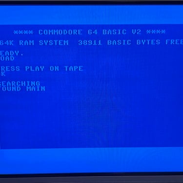
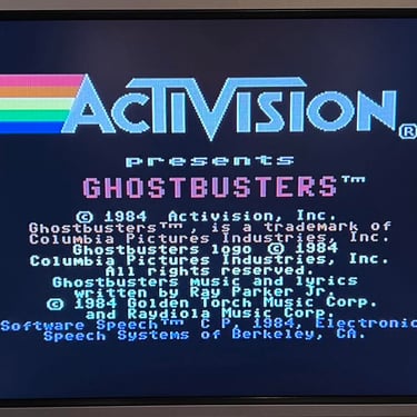
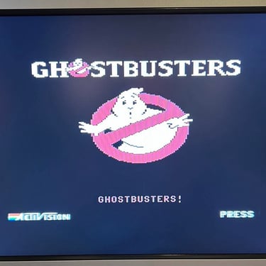
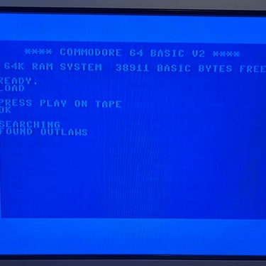
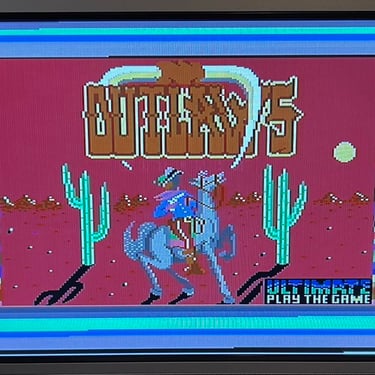
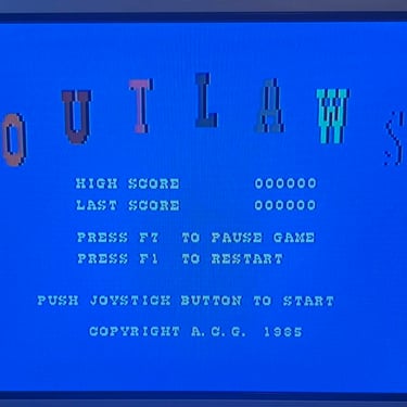
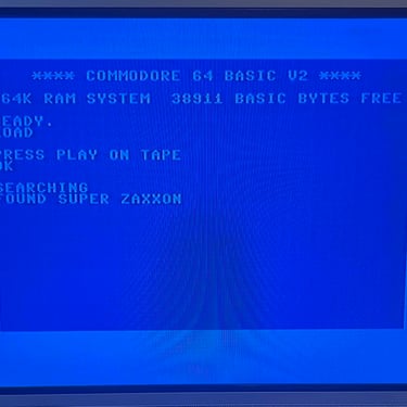
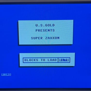
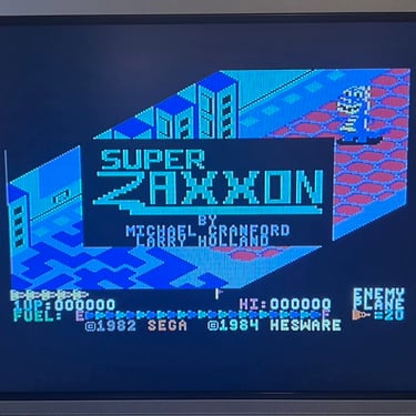
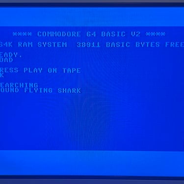
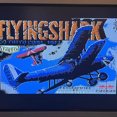
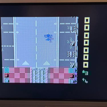
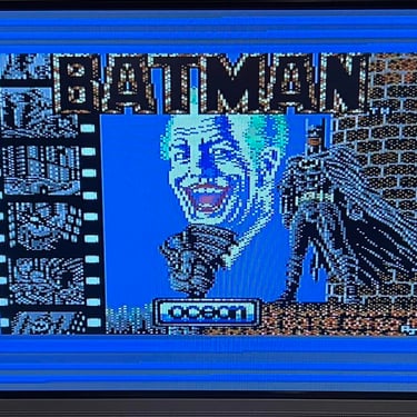
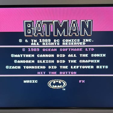
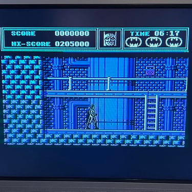
To make sure now works as it should I select five original C64 games to be used for testing. Even if these games are old and worn the load without any problems at all. Below is a picture gallery from the testing.

Recording
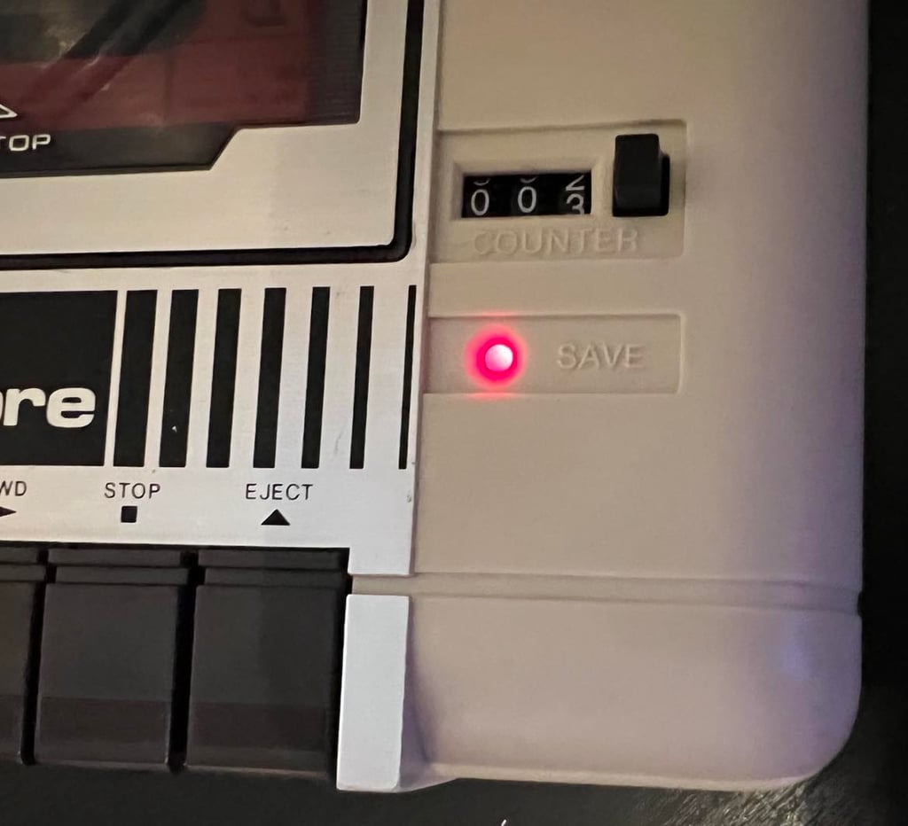
The saving functionality is also checked and verified. A small BASIC program is made and the SAVE command is used (and then the program is re-loaded). The LED is also on while recording is in progress.

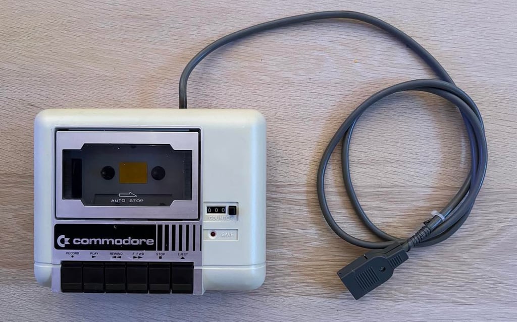
Final result
"A picture worth a thousand words"
Below is a collection of the final result from the refurbishment of this datasette. Hope you like it! Click to enlarge!

Banner picture credits: Evan-Amos