

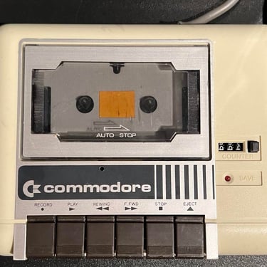
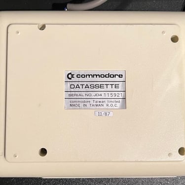
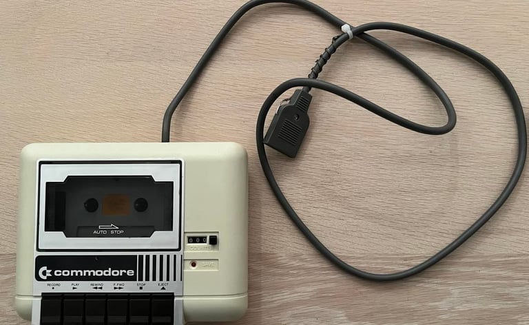
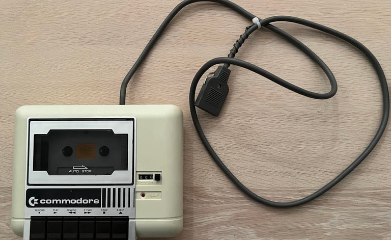
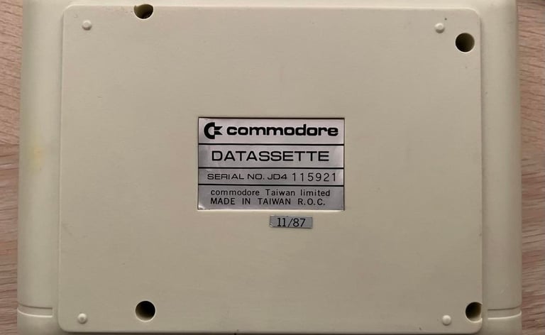
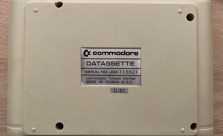
1530 (C2N)
Ser. No. 115921
To refurbish this datasette the plan is to do this trough the following steps (some of these in parallell):
- Clean and remove stains from chassis
- Clean the interior mechanics
- Replace motor- and counter belts
- Check PCB for corrosion and replace old electrolytic capacitors
- Adjust head for optimal tape reading
- Verify datasette operation by testing
Refurbishment plan
Chassis
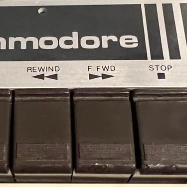
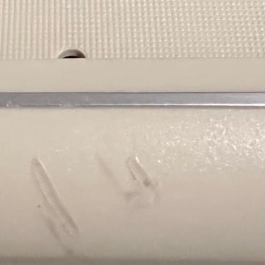
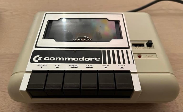
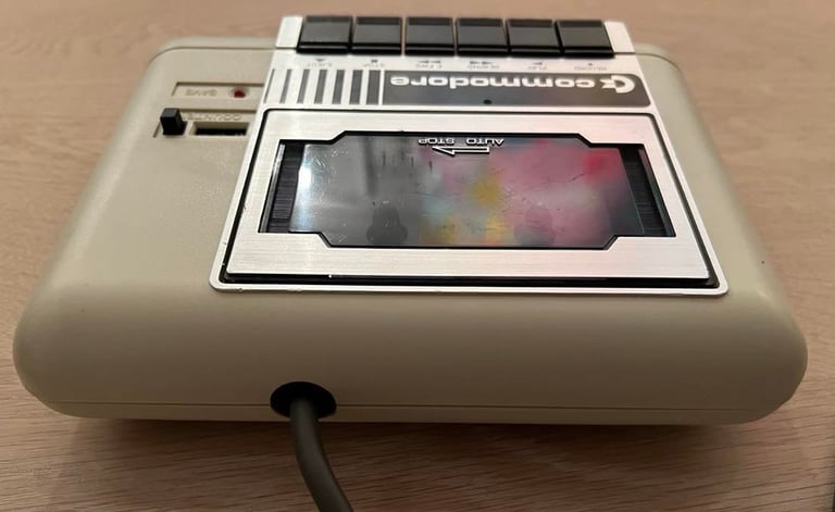
I´ve had this datasette for a while so I think I gave the chassis a wash some time ago. Anyhow, the chassis looks quite ok I think. There are some scuff marks and also marks from cables which have been wrapped around the chassis and on the FF and STOP key (these marks looks like "melted" plastic, but is the result of cables wrapped around the chassis for a long period).
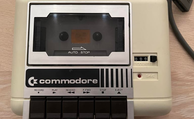
Below you will find pictures of the staring point of this datasette - before I start the refurbishment.
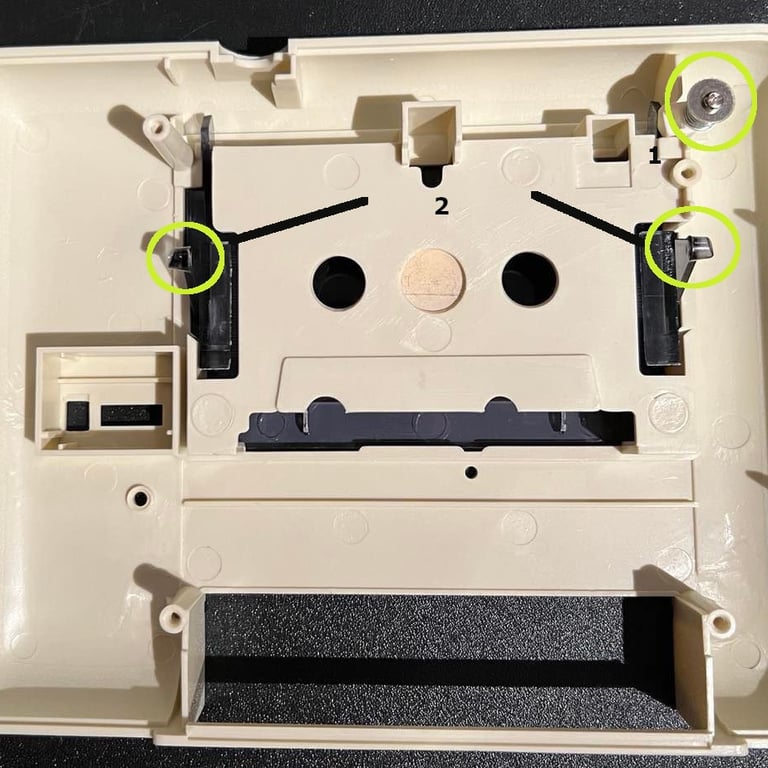
To disassemble the datasette the four screws at the bottom are removed. With the top- and bottom cover separated the interior mechanical assembly is removed. Even if this datasette is cleaned previously I choose to remove the lid again. This is done by removing the screw (marked in position "1") and gently pushing the two brackets towards the middle (marked in position "2"). See pictures below.
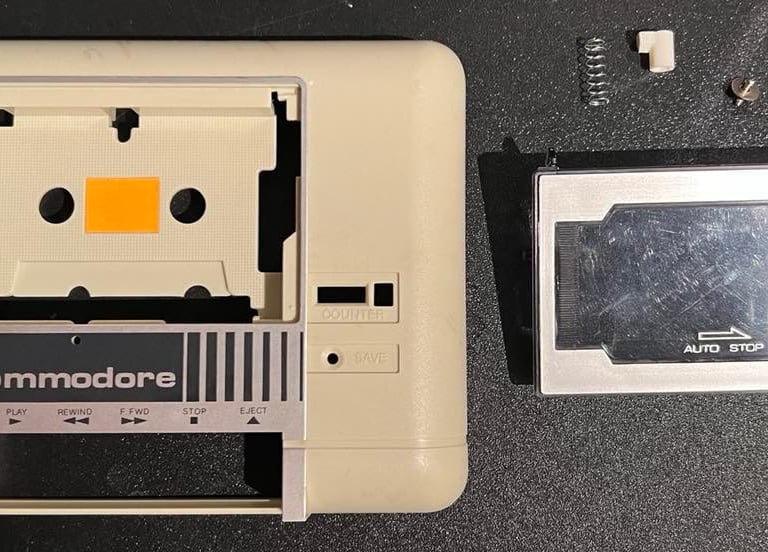
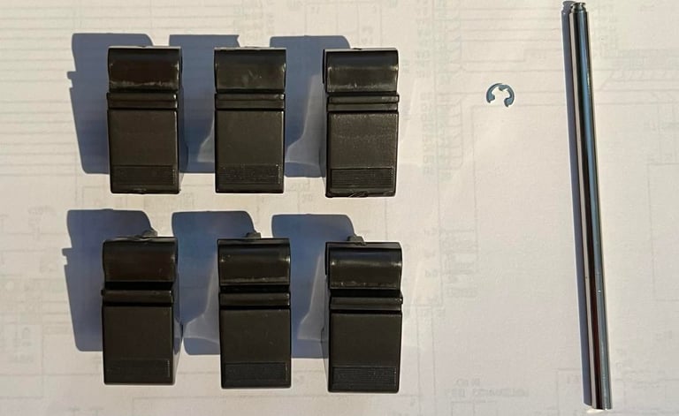
All the keys are disassembled from the interior. This is done by removing the small clip on the right hand side of the keys, and then the axle is pulled out. A warning here: note that there are three small Y-shaped springs on back where the keys are attached to the metal. When the axle and the keys are removed these springs easily fall out - so make sure to secure them in a smart place.
The keys are left in mild soap water (cold) overnight. Then they are dried and cleaned with glass cleaning spray. The result of this cleaning is shown below.

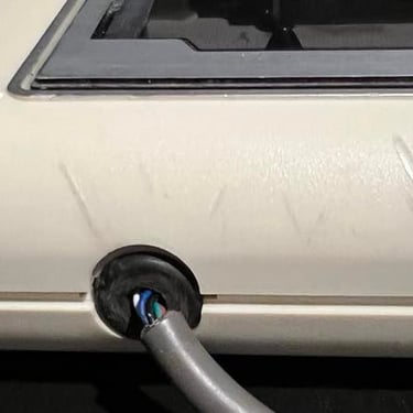
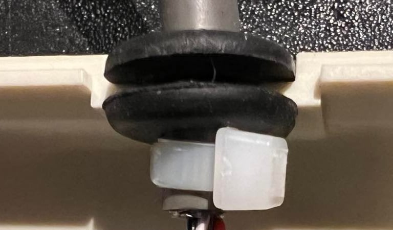
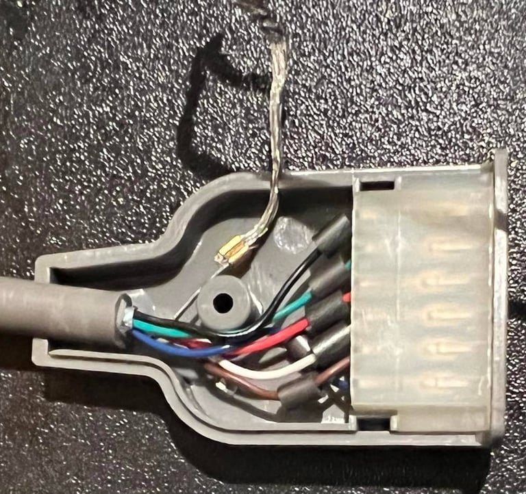
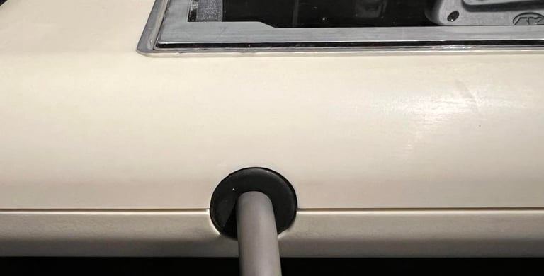
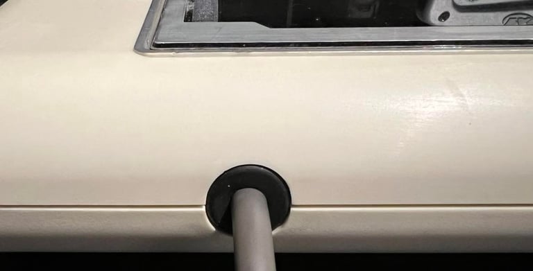
The cable has been dragged out of the chassis (trough the rubber ring). To make sure it stays in place I add a small cable tie inside the chassis to make sure it doesn´t come out.

I check the cable connector to make sure everything is ok (which it is). Also, I use a cable tie around the ground cable to prevent it from getting into the user port and short cut something. This ground cable is not used anyway on the Commodore 64.

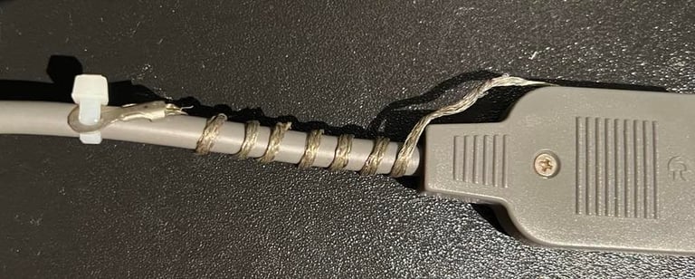
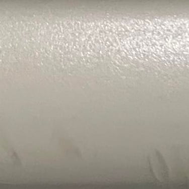
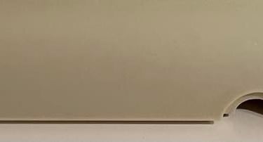
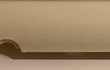
There are quite a few marks from where the cable has been wrapped around the datasette. These marks looks like "melted" plastic, but are the result of a chemical reaction from the cable and the plastic from the chassis. To remove these I carefully sand the these marks first with some wet P240 sanding paper. When the marks are not visible anymore I use wet P1000 sandpaper to remove most of the stripes that come from the sanding. I think the result is quite good. The areas which are sanded are a bit more smooth/polished than the rest of the chassis, but I still think it´s much better. Unfortunately, I get some water below the yellow sticker in the top cover. This results in some marks on the sticker. Nothing to do with that (lessons learned).
Below there are four pictures. The first two shows the original marks, and the last two show the chassis after the sanding. Click to enlarge.
The rubber ring around the cable is now tight (with the cable tie behind it). Looking quite nice!
Interior mechanics
To clean the interior of the datasette I use a combination of pressurized air, isopropanol and mild soap water. The whole of the interior (back and front) is first cleaned with compressed air. There is quite a lot of dust in there, but otherwise the interior looks quite good. I can´t see any kind of damage or large parts of corrosion. Then everything is cleaned with a Q-tip dipped with isopropanol.
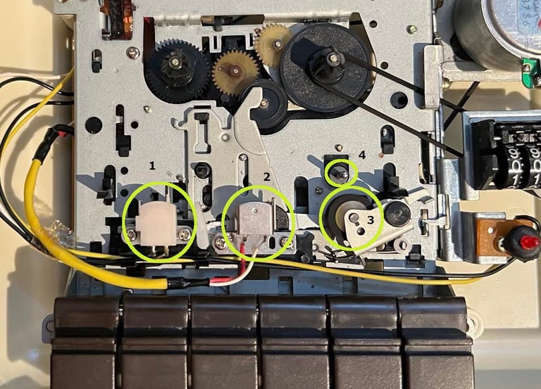
When cleaning the interior there are four areas that are very important, and require special attention:
Erase head
Read/write (RW) head
Pinch roller
Capstan
Below is the picture of the cleaned datasette, and also the position of 1-4.
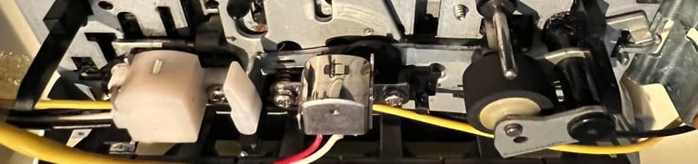
And a close up picture of the cleaned erase head, R/W head, pinch roller and capstan. Click to enlarge.

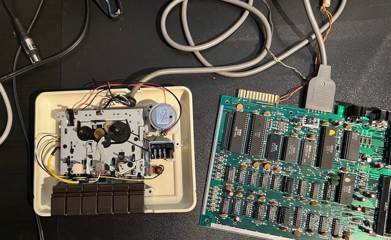
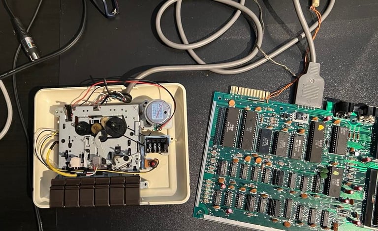
A small advice on cleaning the pinch roller and the capstan is to this while they are rotating. To do this I connect the datasette to a C64 and power on. Then using the FF/REW/PLAY keys I start rotating all moving parts. And clean them while they rotate. Below are two short videos showing the cleaning, and a picture of the setup.
Replacing the belts
There are two belts in the datasette, one for the counter and one for the motor. It´s essential to replace the motor belt since this belt is a vital part of the datasette. If the motor belt is too loose, damaged or too tight the datasette will not operate as expected. The counter belt is not that crucial to replace, but it´s good practice to do that. And there are some games which rely on the counter in order to function.
Also notice that there are for the 1530 datasette two main versions; the "Made in Taiwan" and the "Made in Japan". The interior of these are quite like, but there are some differences. And especially the belts are different. This datasette is the "Made in Taiwan" version. I use belts ordered from dataserve-retro.co.uk.
To remove the motor belt there are two screws that needs to be removed. In the picture below you will see the position of these two screws. A little note / warning: when the two screws are removed you don´t remove the whole bracket. Just loosen it slightly to get the belt out of the bracket. If you are not careful on this operation you risk that the little spring in the back of the bracket will fall out - not impossible to get back but could be a quite annoying task.

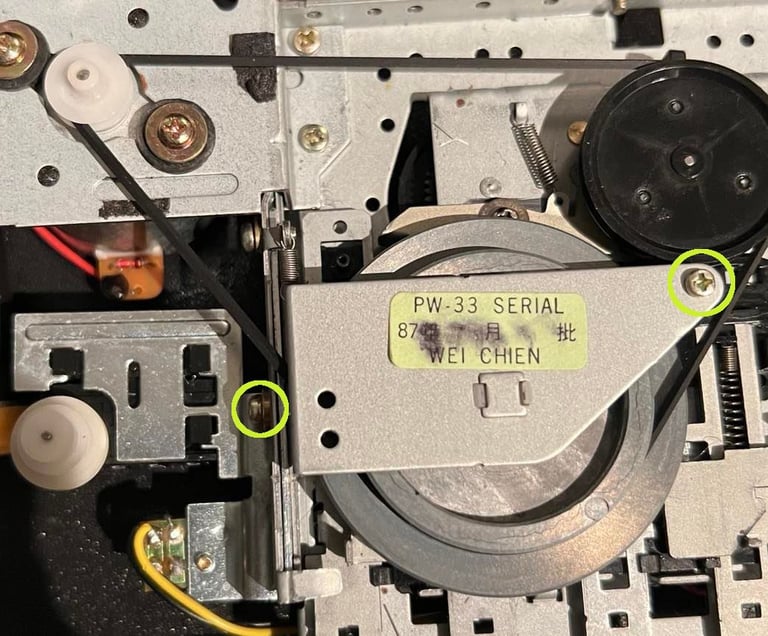
The picture above also show the new motor belt in place. The counter belt is very easy to replace - no screws need to be removed. Just lift the little "arm" above the belt. Picture below show the new counter belt in place.
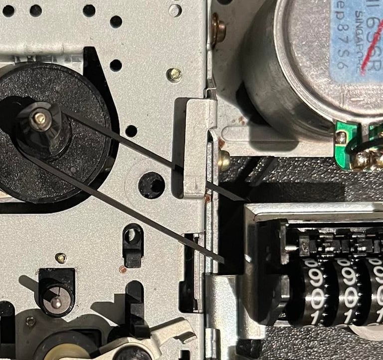
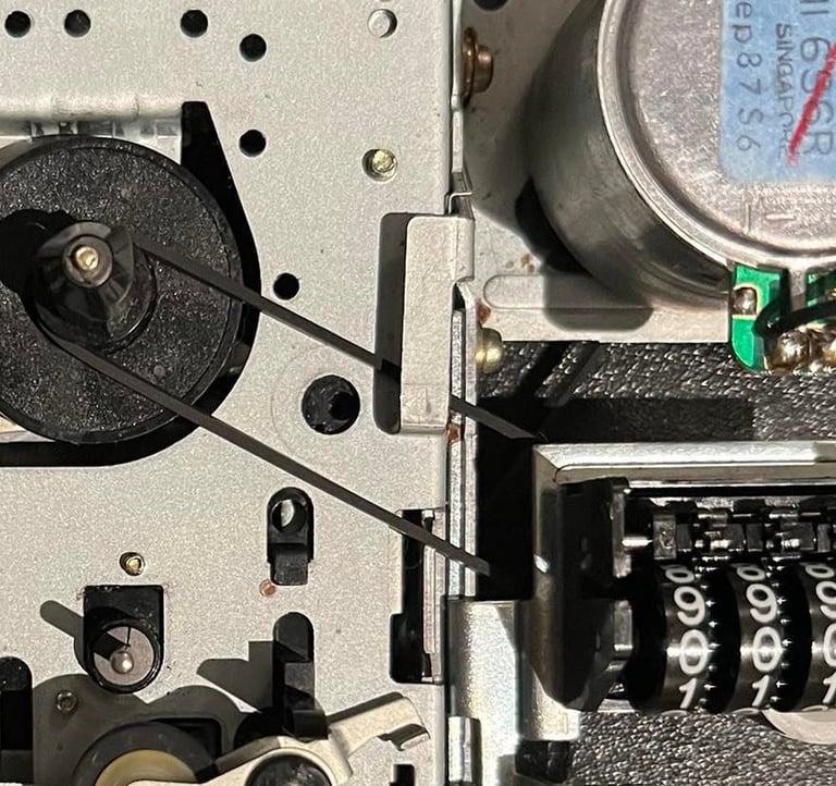
The picture above also show the new motor belt in place. The counter belt is very easy to replace - no screws need to be removed. Just lift the little "arm" above the belt. Picture below show the new counter belt in place.
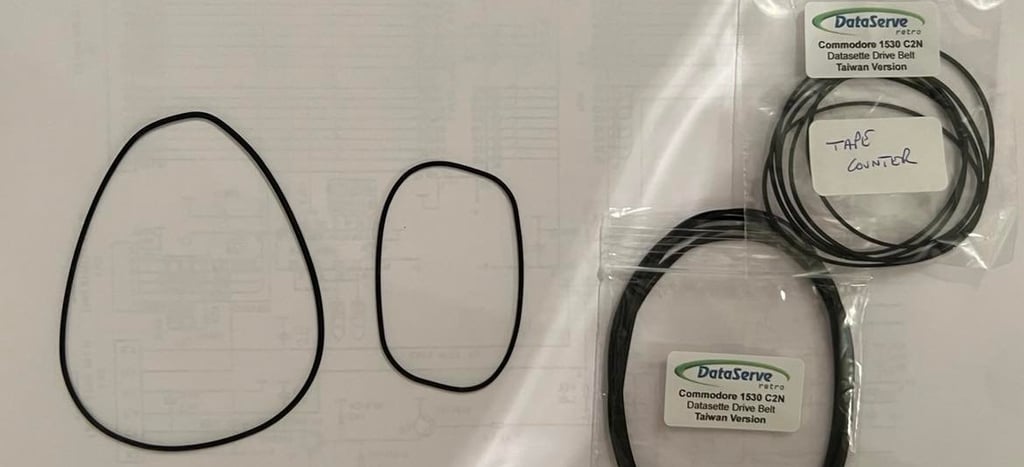
The old belts are far from the worse I´ve seen. There are some signs of "hard bends" from the static position the belt have had for years, but the flexibility seems to be quite ok. Nevertheless, it´s always good to replace them for optimal datasette operation. See picture below to see the old belts (to the left), and to the right you see the bag of belts I pick the new ones from.

PCB and electrolytic capacitors
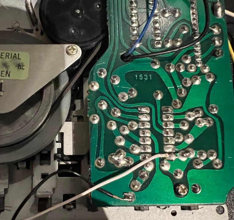
The PCB is cleaned and checked for any faults or corrosion. The PCB looks hunky dory! I can´t see anything wrong with it. PCB is cleaned thoroughly with isopropanol. See picture below.
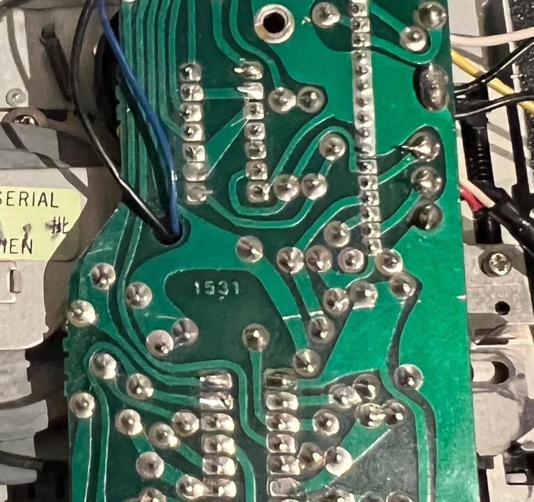
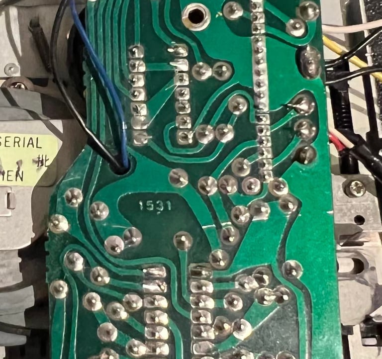
There are three electrolytic capacitors on this datasette. All of which are 47 uF [16 V]. I replace these with Wurth Electronics capacitors ordered from https://no.mouser.com/ - all with same capacitance and voltage marking. See picture below (the front of the PCB is also cleaned with isopropanol). Click to enlarge.

Read/write head alignment
It´s essential that the R/W head is aligned for optimal performance. I use a combination of oscilloscope and a C64 azimuth software to control and verify the position of the R/W head.
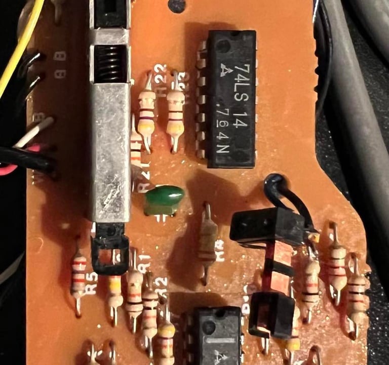
While reading an article in the blog world of jani I noticed that he used the 2nd stage of the OP-Amp chain as good position to connect a VU-meter - and that also turns out to be a good place for probing with the oscilloscope. In the figure below you see the chains of OP-Amps in the datasette. The 2nd stage output an amplified signal, but not so amplified that it´s clipped.
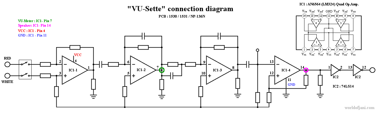

According to this figure the 2nd output is on pin 7 on PCB (version 1531) which is the one we have here. I solder on two wires here; one to pin 7 and and to ground.

Now to get optimal R/W head position the method I use is:
Assemble the whole datasette - but with the two "new" cables sticking out of the chassis
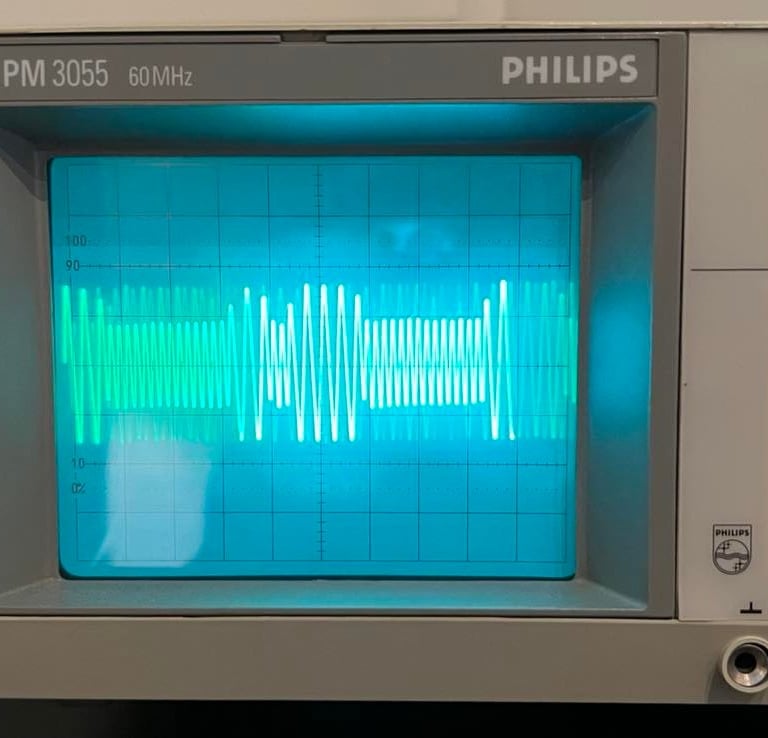
With the oscilloscope attached to the cables, I insert an original tape in the datasette and press play. When the signal occur on the scope I carefully turn the little screw until I reach the maximum amplitude.
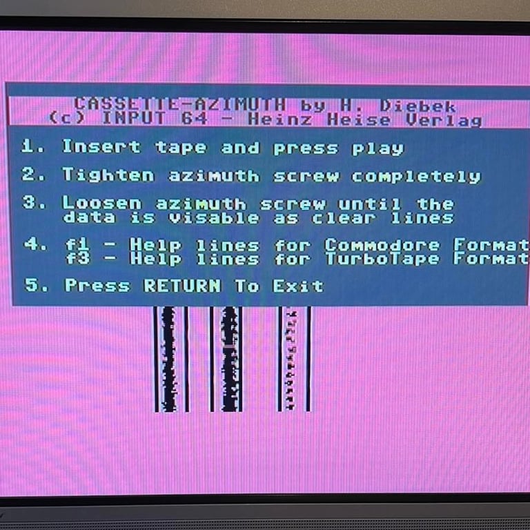
When I think that I´ve reached maximum amplitude I use the C64 cassette-azimuth software to verify that this is the correct position. This you can see if all three lines appear as solid lines.
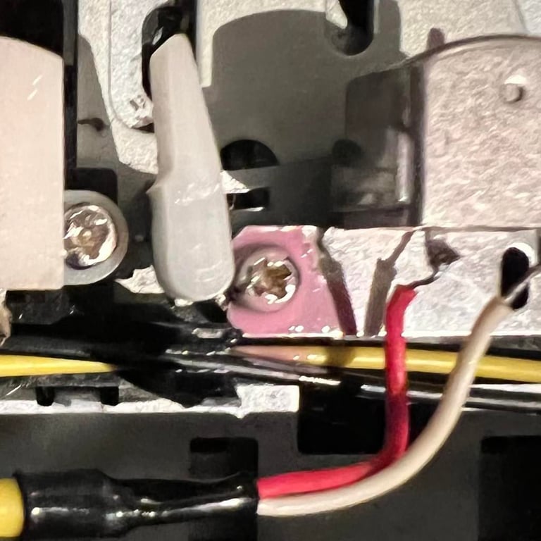
If everything is ok I use a touch of nail polish to "lock" the screw in position
Below is a little gallery from the process; the signal on the oscilloscope, the C64 cassette azimuth software with three lines and the nail polish on the R/W screw.
There are also two small videoclip from the R/W head adjustment operation:
Adjustment of 1530 datasette 115921 with oscilloscope and azimuth software
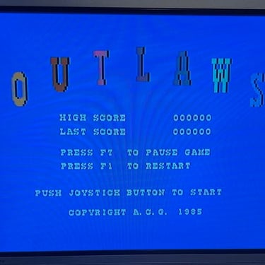
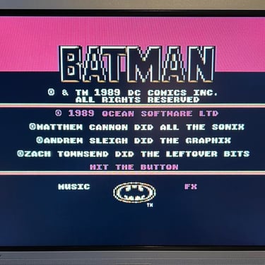
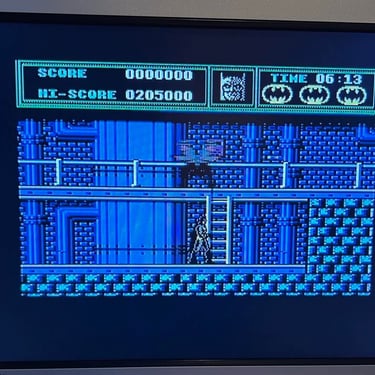
Controlling the 1530 with the oscilloscope and Batman game (TURN UP THE VOLUME! OCEAN LOADER!)
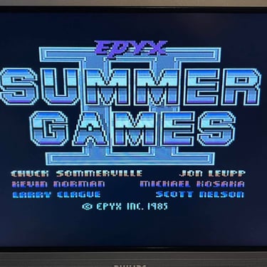
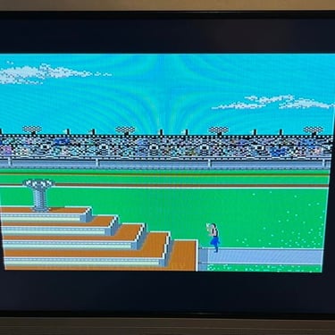
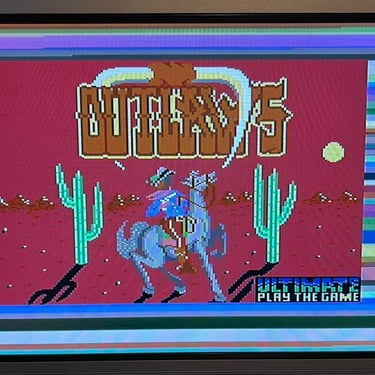
Testing
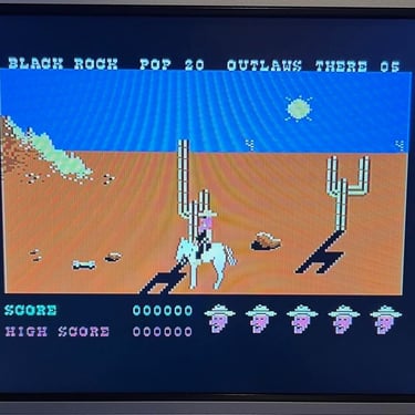
Ok, moment of truth! Or... well... not that much maybe. A lot of testing is already done during R/W head adjustment, but I always verify that the datasette works with three original (OLD!) games. Note that old games tend to wear out, so even if games works ok here there is no guarantee that all old games will work. And the testing is also a kind of celebration of a completed refurbishment!

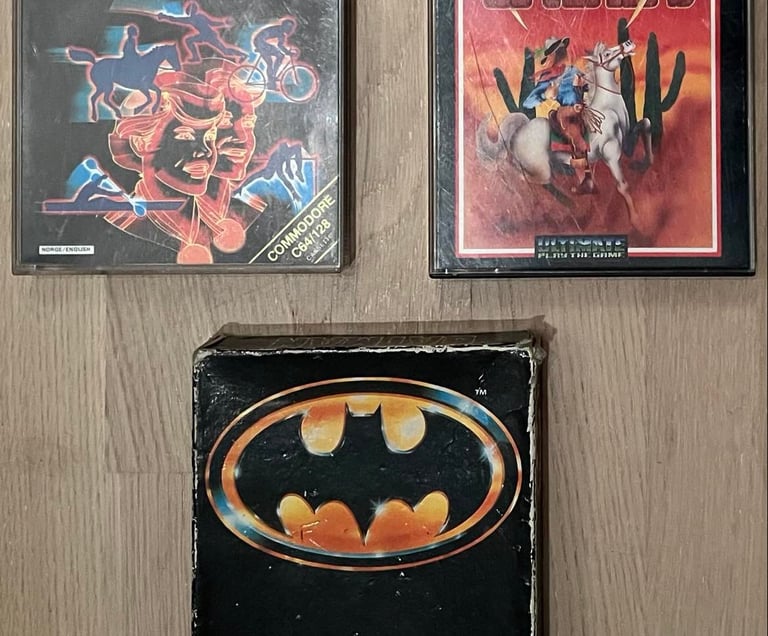
Below is a small picture gallery from the testing of these games. I conclude that this datasette is now tested ok!

Final result
"A picture worth a thousand words"
Below is a collection of the final result from the refurbishment of this datasette.
Hope you like it! Click to enlarge!


Banner picture credits: Evan-Amos