

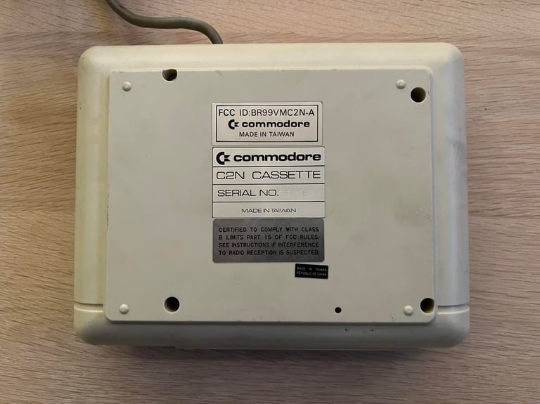
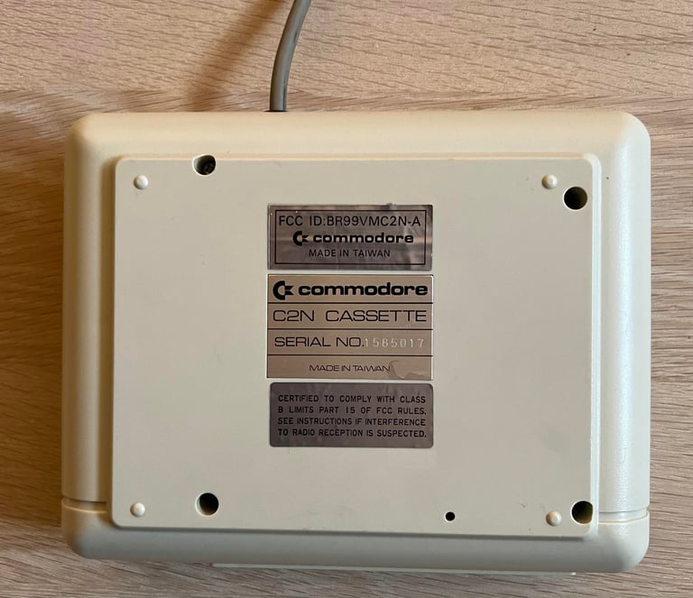
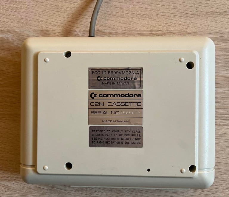
1530 (C2N)
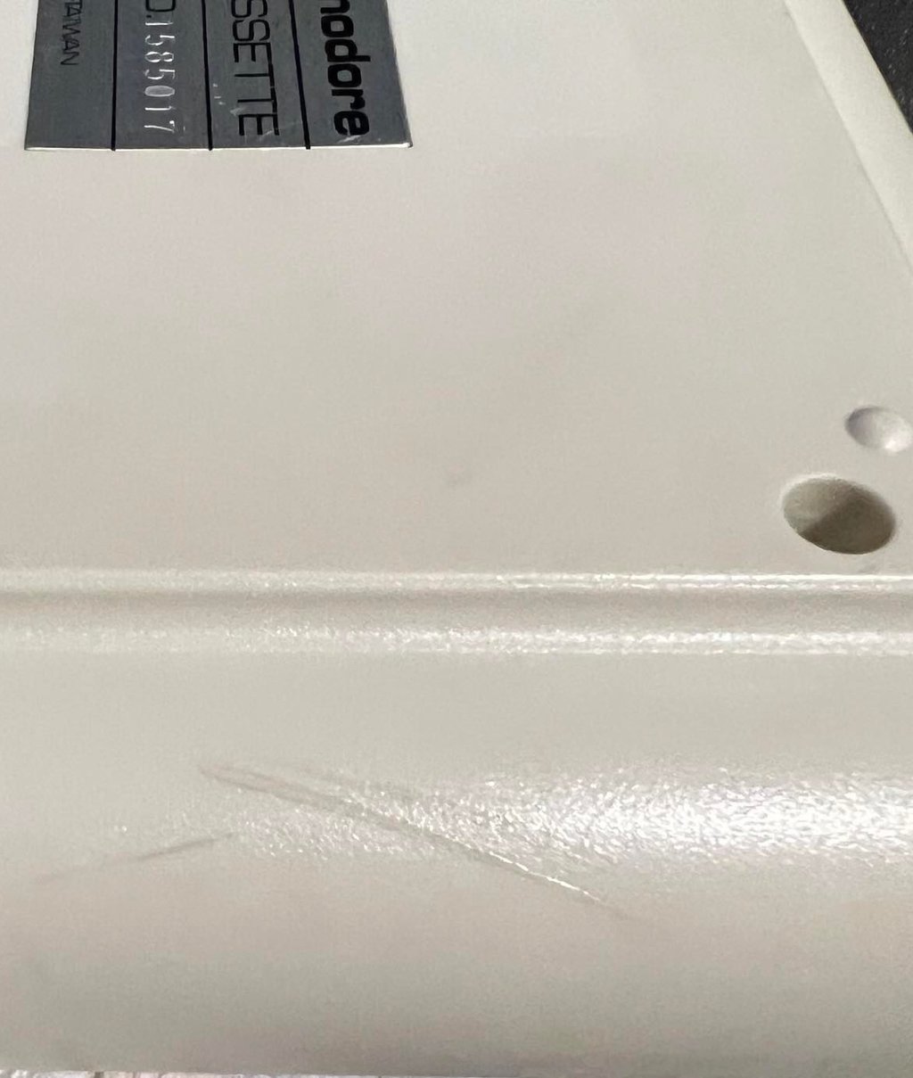
Ser. No. 1585017
Starting point
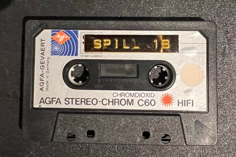
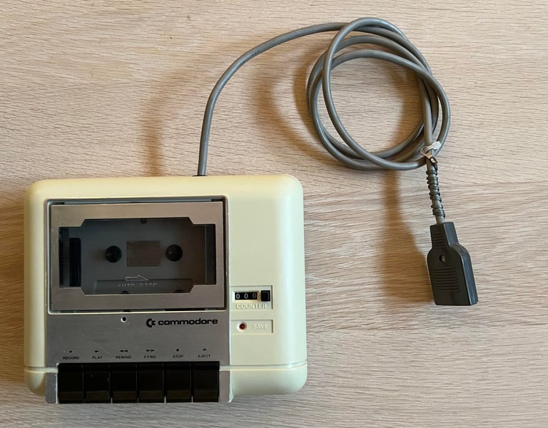
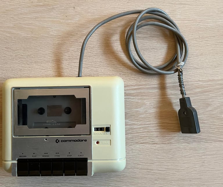
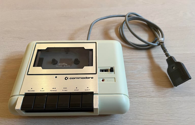
I have no idea if this datasette works or not, but I think it looks promising. It is dirty, and full of stains and marks, but it looks undamaged. There also a nice cassette tape with the datasette marked "SPILL 1B" which translates from Norwegian to English "GAMES 1B". Would be fun to see if there are some gems here if this tape works!
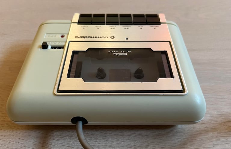
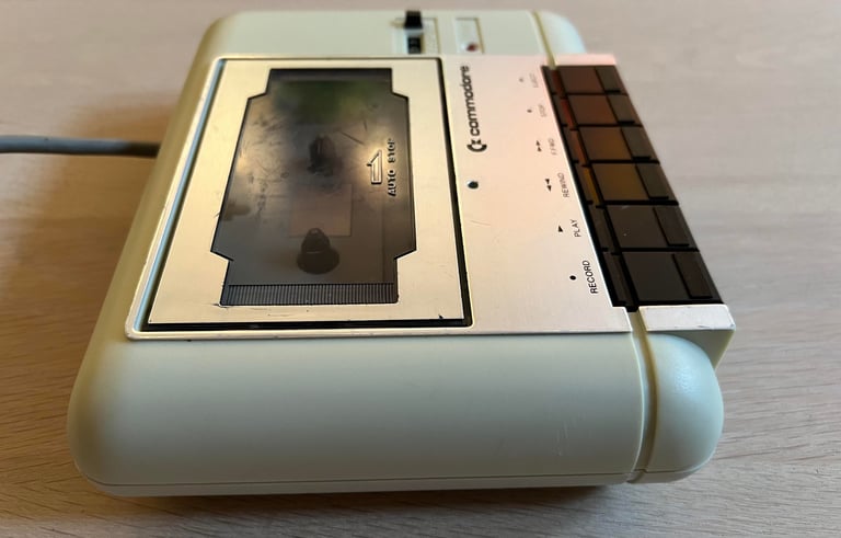
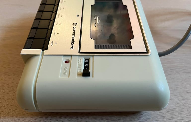
Below is a gallery of pictures of the datasette before refurbishing begins.
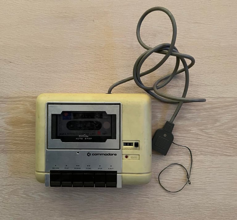


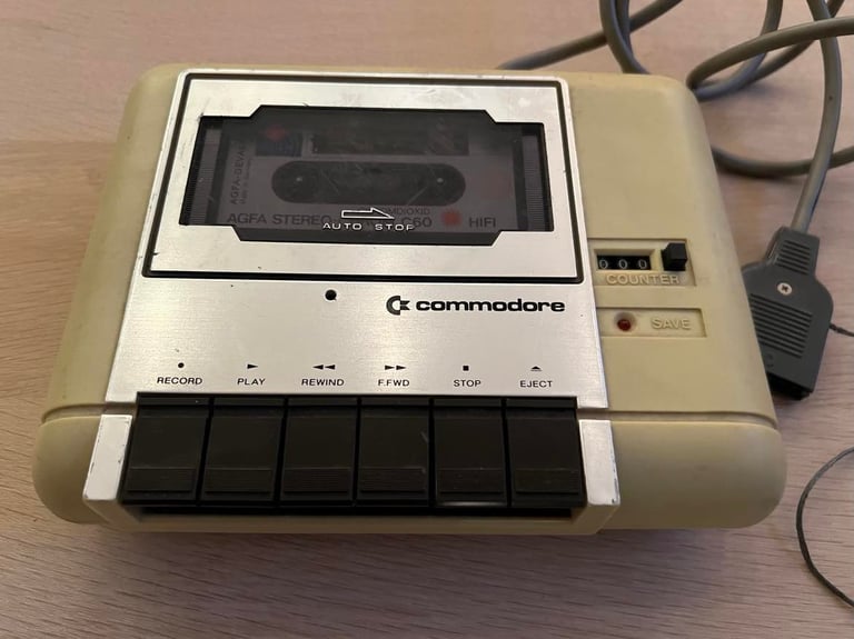
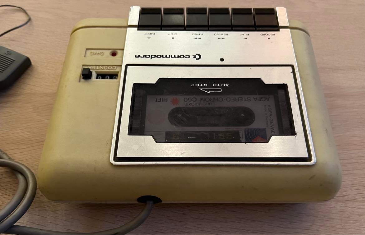


Mystery tape; AGFA Stereo-Chrom C60 tape. Made in Germany.

Refurbishment plan
To refurbish this 1530 datasette the plan is to do this trough the following steps:
- Clean and remove stains from exterior casing
- Clean the interior mechanics
- Check cable and replace strain relief
- Check PCB for corrosion and replace old electrolytic capacitors
- Replace motor- and counter belts
- Adjust head for optimal tape reading
- Verify datasette operation by testing
Note that several of these steps are done in parallell.
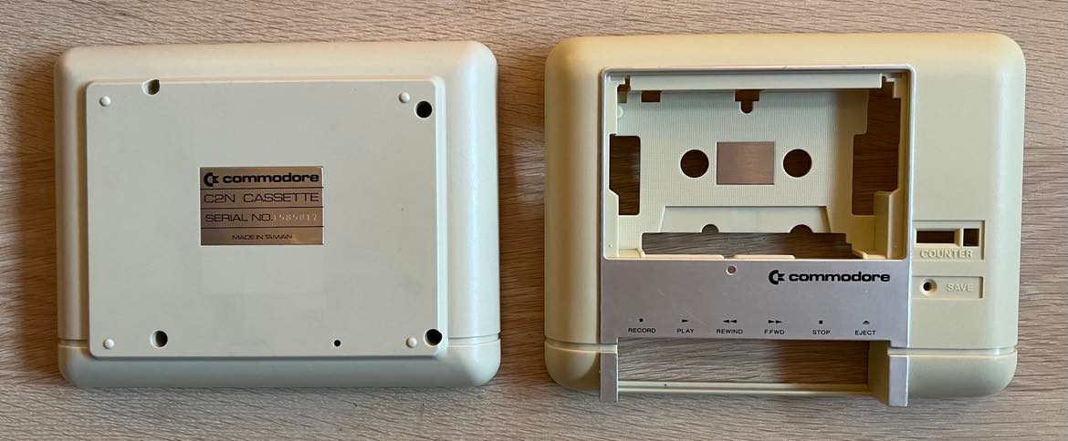
Exterior casing
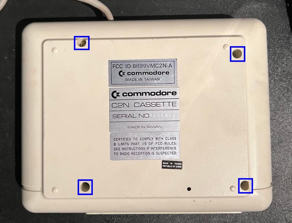
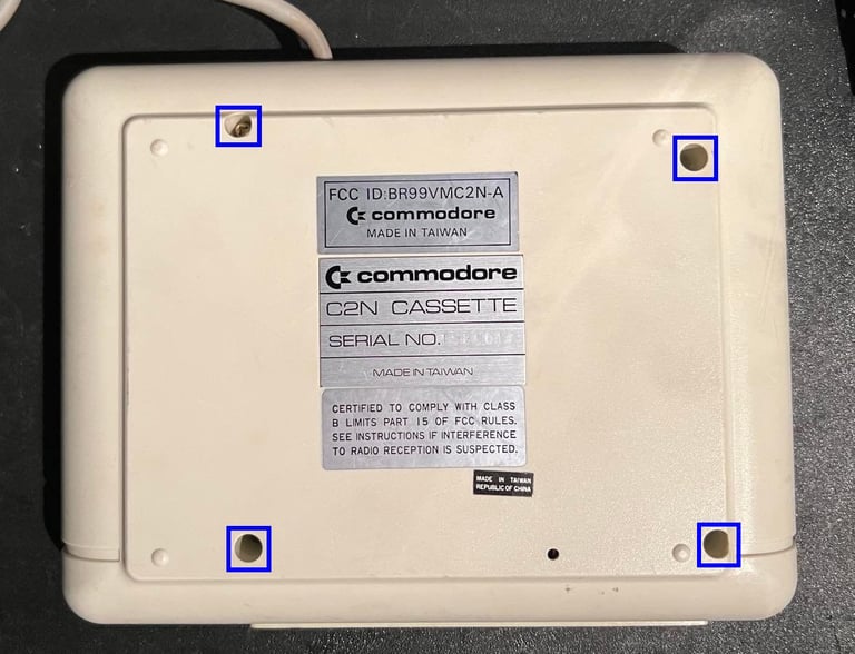
The exterior casing consists of a top- and bottom cover. The top cover also contains a tape lid. To separate the casing in the different parts the top- and bottom cover are separated by removing the four screws at the bottom. See picture below.
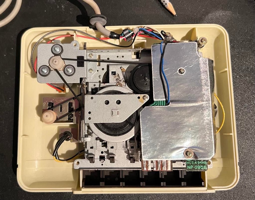
This will reveal the interior of the datasette. In this model it is just to lift the interior out of the top cover - no screws need to be removed.
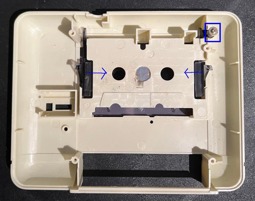
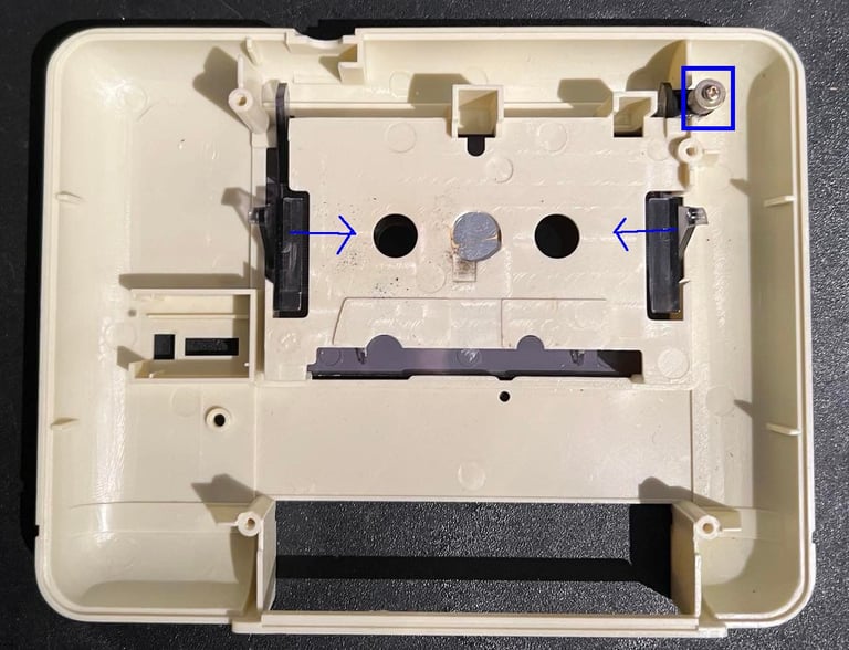
To remove the tape lid from the top cover first remove the screw (blue square picture below). Then remove the spacer, spring and little plastic part which the screw was holding in place. Next, gently push the two plastic levers (blue arrows) towards the centre of the top cover. Push firmly from the backside and the tape lid will come out.
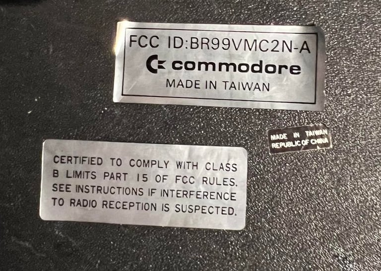
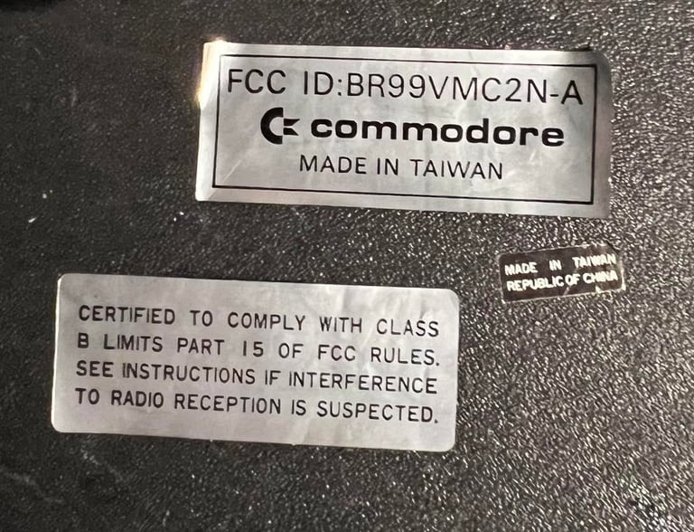
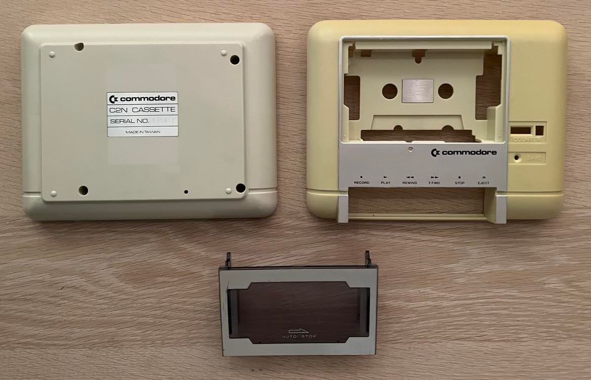
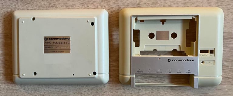
Most of the stickers are removed from the bottom cover before cleaning. The metal badge with the serial number is not removed. I´m worried that I might damage it removing it. All stickers are removed with a sharp knife while applying hot air from a hair dryer. Below are pictures of the stickers and of all the parts before cleaning.
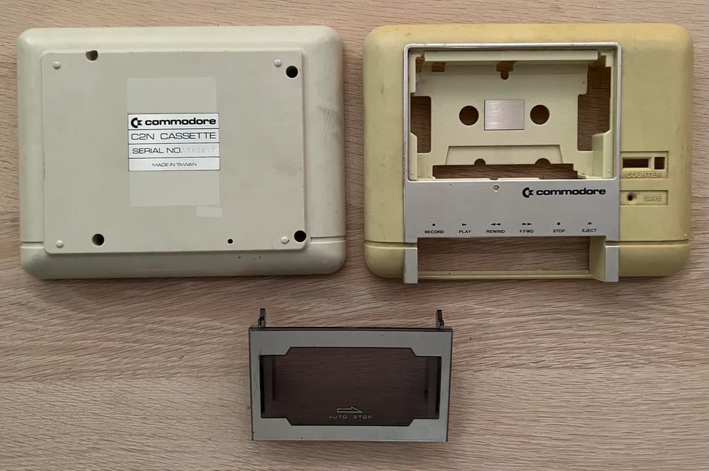
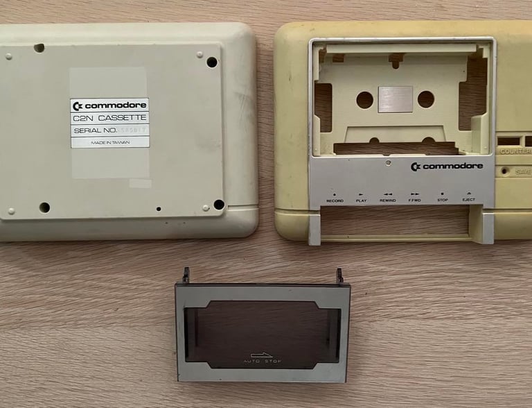
All plastic parts are cleaned thoroughly with mild soap water and a paint brush. After this initial cleaning there are still quite a few marks that needs special attention - see pictures below.
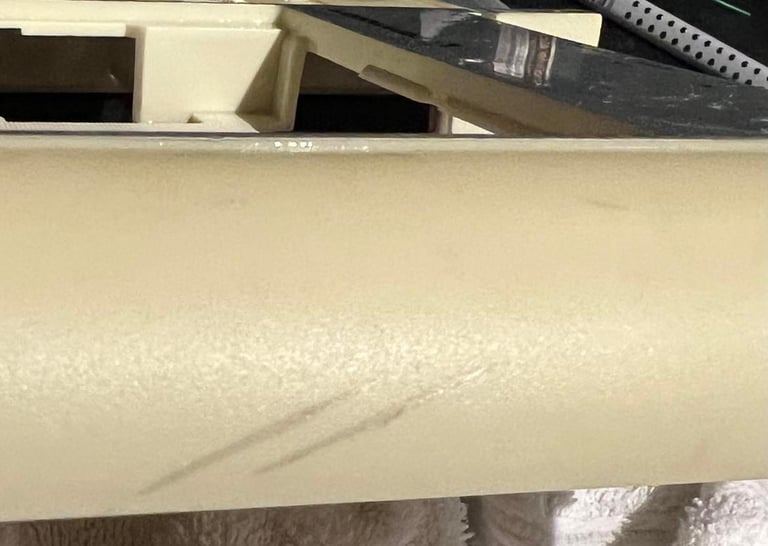
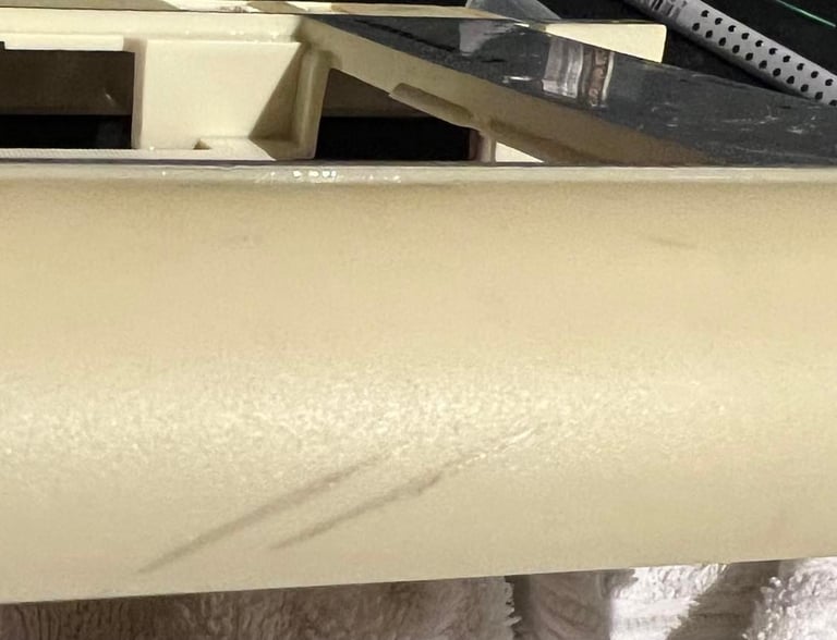
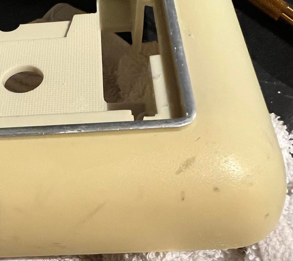
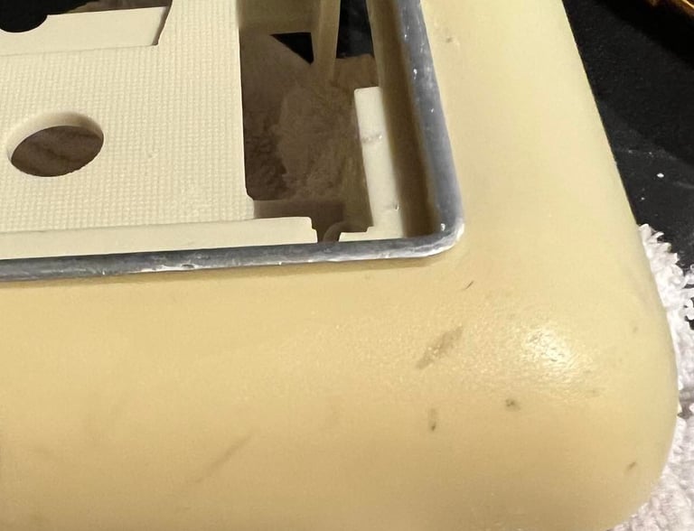
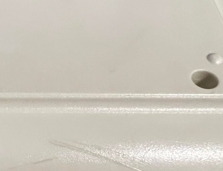
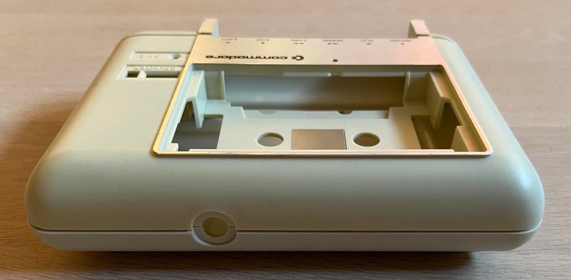
These marks are removed by using a combination of isopropanol and baking soda. As a final cleaning all parts are (again) cleaned with mild soap water, dried and then cleaned with glass cleaner. Below is a picture of the three parts after cleaning. The top- and bottom cover will be retrobrighted later, but first I will clean the keys.

Top- and bottom cover is retrobrighted for about 10 hours in a UV-box. The plastic parts are smeared frequently with 12 % hydroperoxide cream.

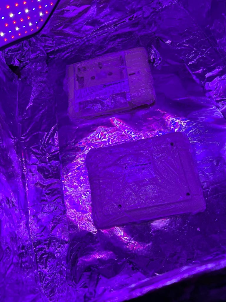
Result is good, but it is not perfect. The top cover is still yellowed than the bottom cover. But I don´t think it is possible to get it better than this. Nevertheless, I am quite happy with the result. It is way better than before retrobright.

Interior mechanics
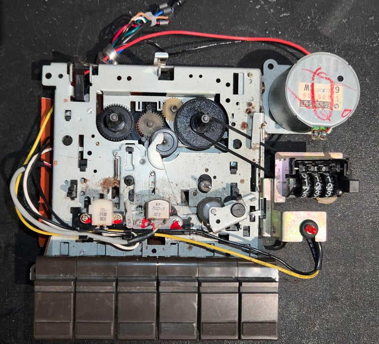
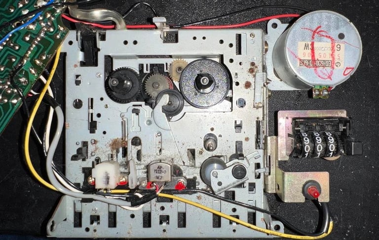
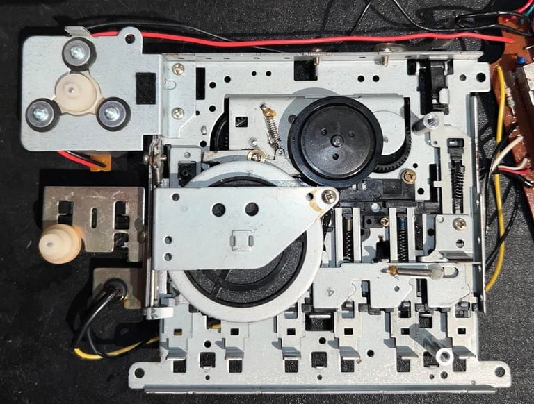
The interior of the datasette is full of dust and dirt. Picture below does not give the right impression I think - it is way much dirtier.
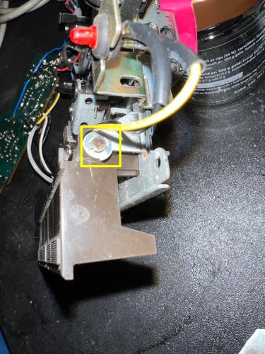
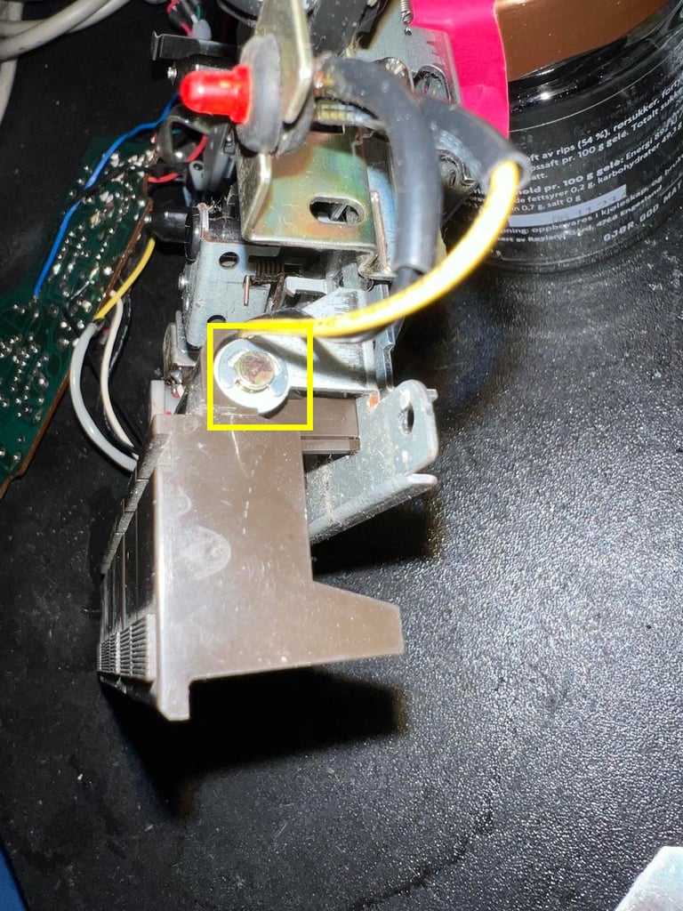
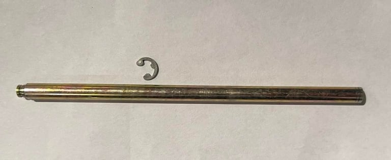
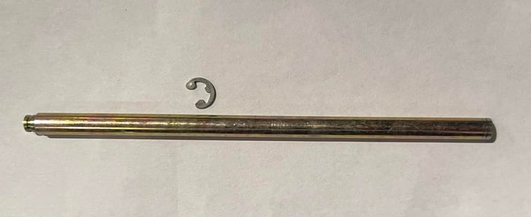
First step is disassembly the keys. I do this both to be able to clean the keys properly and also makes it easier to replenish the grease used in parts of the mechanics. The disassembly is done by first removing the small metal clip (yellow square) and pulling the shaft. See pictures below.
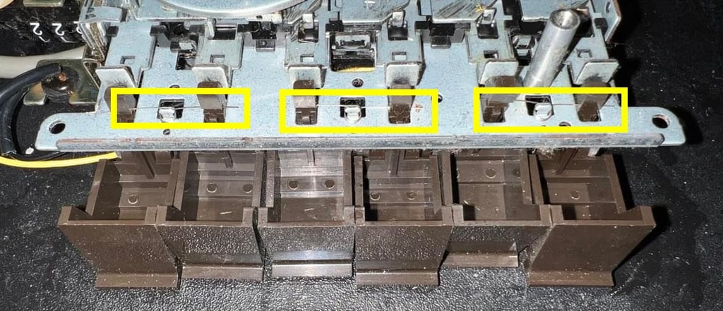
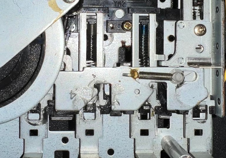
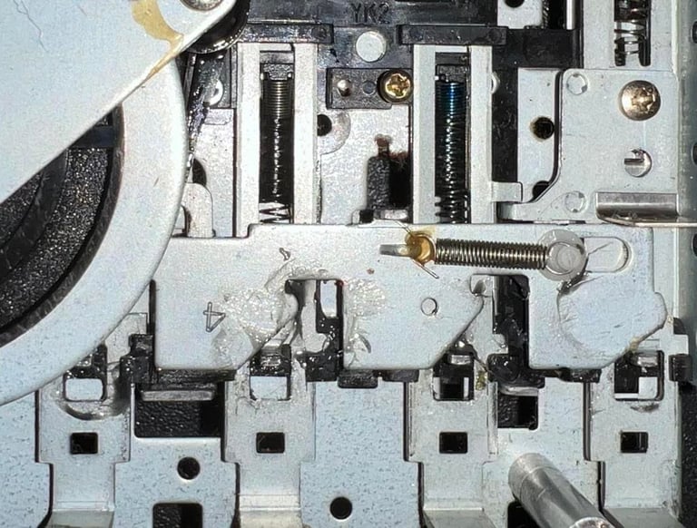
Then the interior is flipped over. Carefully I remove the three small "springs" (yellow squares). As a result all the keys fall out - ready for cleaning!

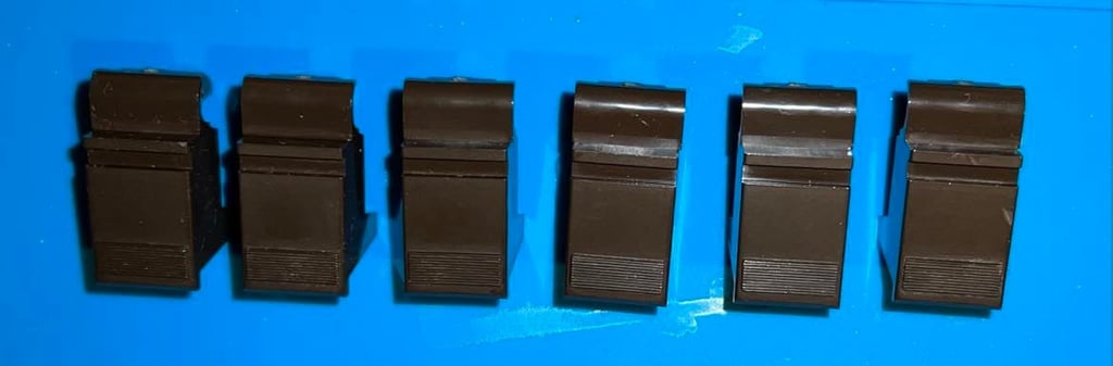
The keys are cleaned by placing them in soap water for several hours and then cleaned with a soft paint brush.

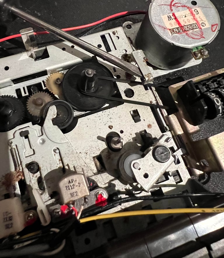
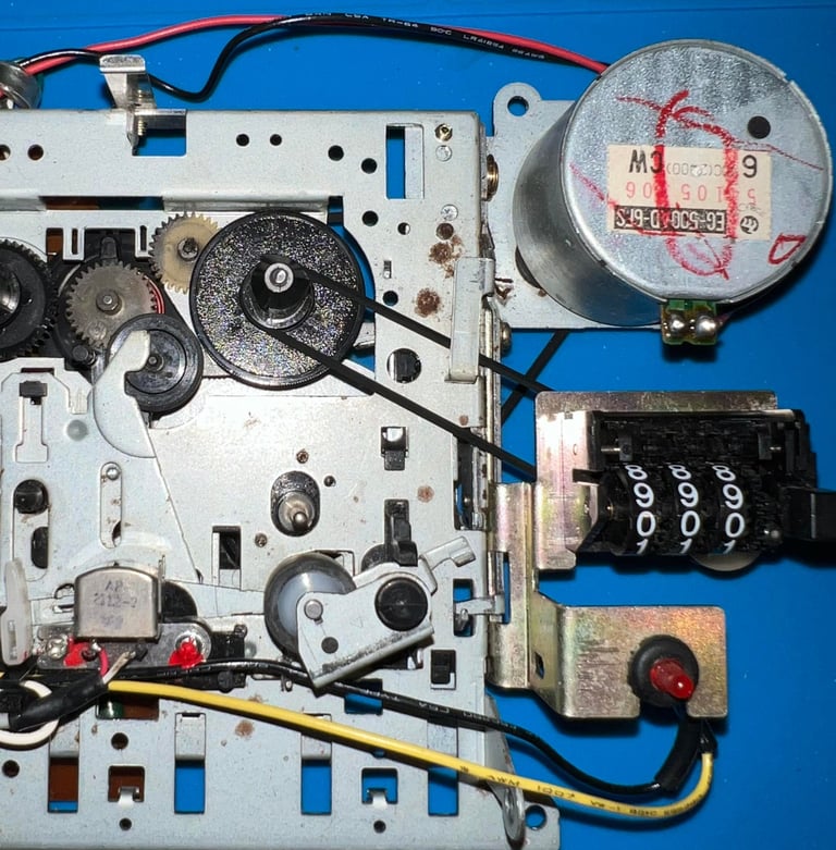
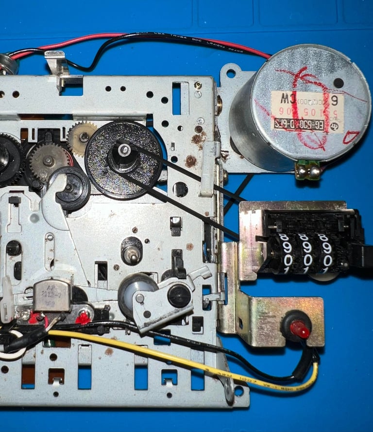
There are two belts in the datasette; one for the counter and one for the motor/flywheel. Both of these belts needs to be replaced since they are old and worn out. To remove the counter belt is straightforward. Only thing required is to lift the small metal "pin" and then remove the belt. Note that there is a small spring holding the small metal "pin" so do not lift it too much. See picture below.
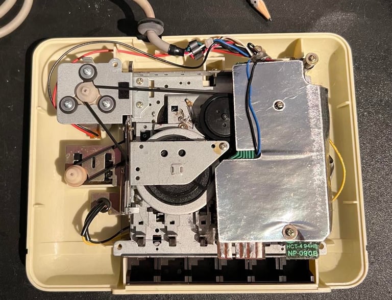
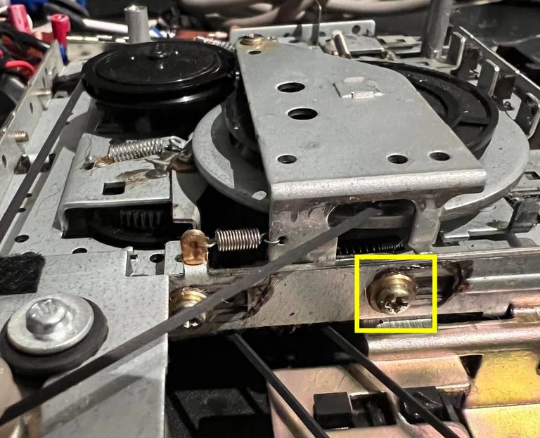
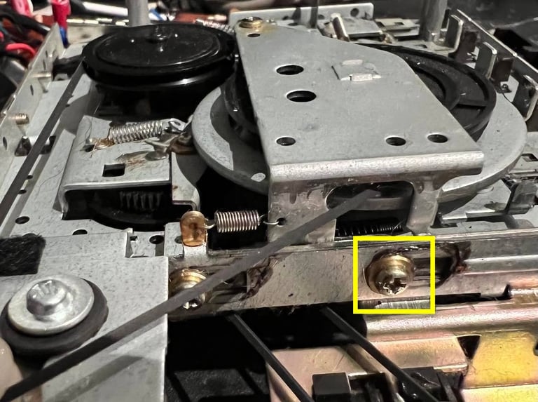
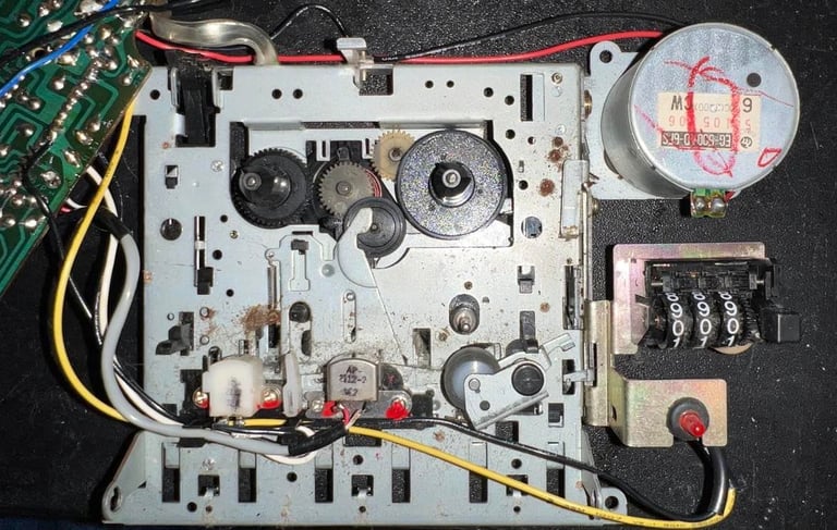
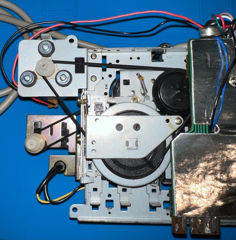
Removing the motor/flywheel belt is not complicated - if you only remove the strictly required screws. Otherwise you can end up with quite a challenge of re-assembling all springs and screws. First, the screw holding the flywheel in place is partially removed - just enough that there is enough room to lift the metal bracket. Blue square in picture below.
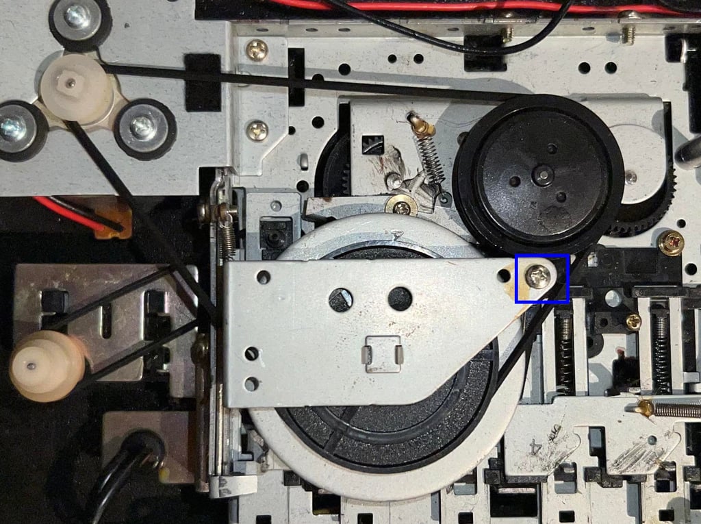
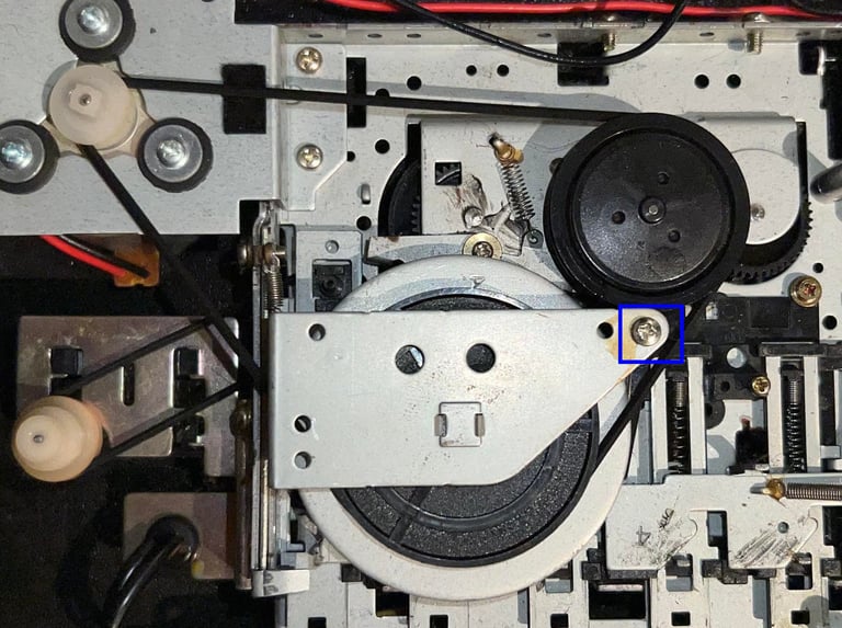
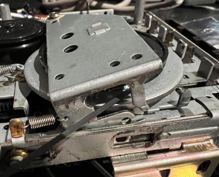
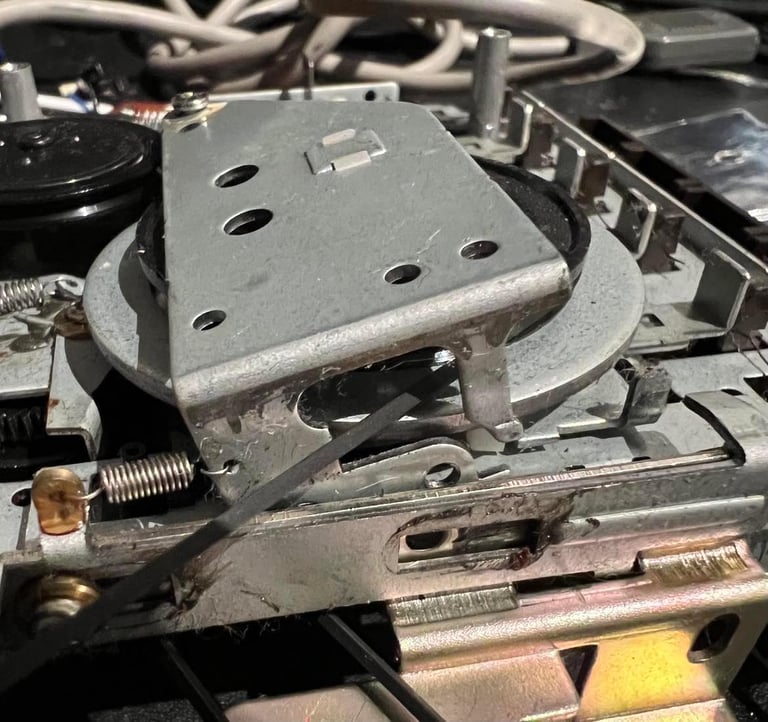
On the side of the metal bracket holding the flywheel is a small screw, and a spacer, which is completely removed (yellow square). Then the metal bracket is partially lifted and the belt is wiggled out of the small notch. See pictures below.
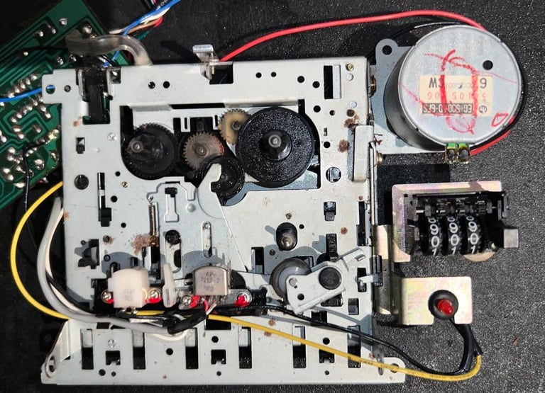
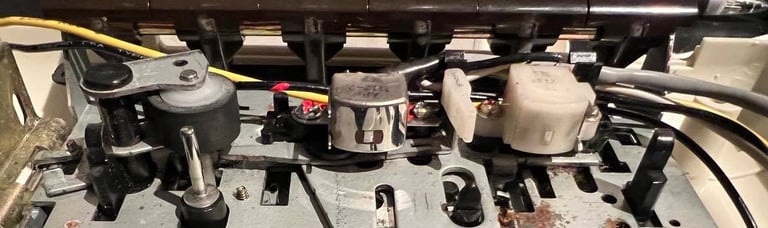
The interior is cleaned throughly properly with isopropanol and Q-tip. The pinch roller, capstan and all rotating parts are cleaned after the new belts are in place. Picture below (left) shows the interior before cleaning and the picture to the right shows the interior after cleaning.
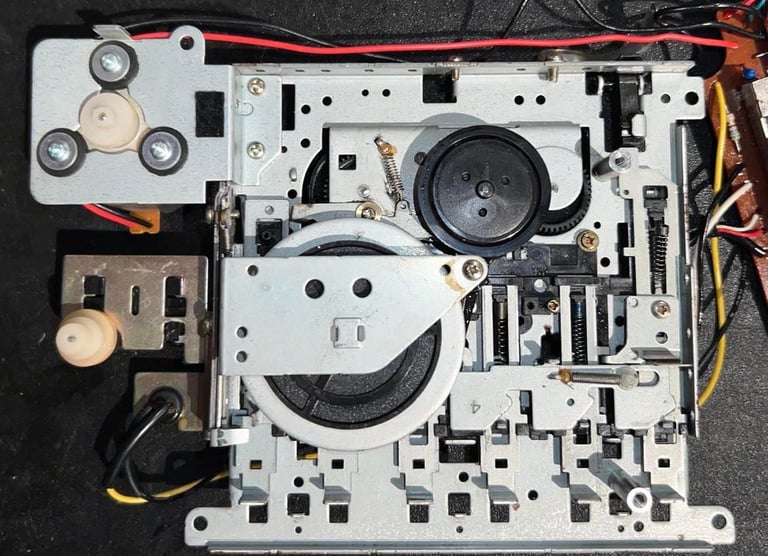
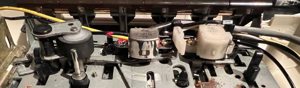
Backside is also cleaned properly with isopropanol...
... and some MoS2 grease is added to moving metal parts.
The last part of the process is to clean the eraser head, read/write (R/W) head, capstan and pinch roller. I choose to do this after the new belts are in place and the keys are reassembled because it make it possible to clean the moving parts more thorough (e.g. gears, capstan and pinch roller). Below are two short videos showing hos this is done for the capstan and pinch roller (not this datasette, but the same method is used in this).


Below is a picture of the cleaned erase head, R/W head, capstan and pinch roller.
Cable
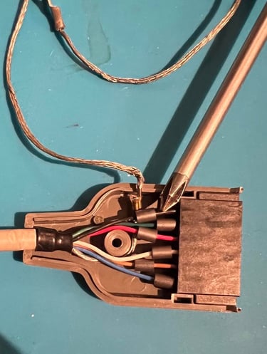
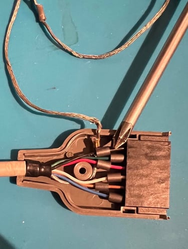
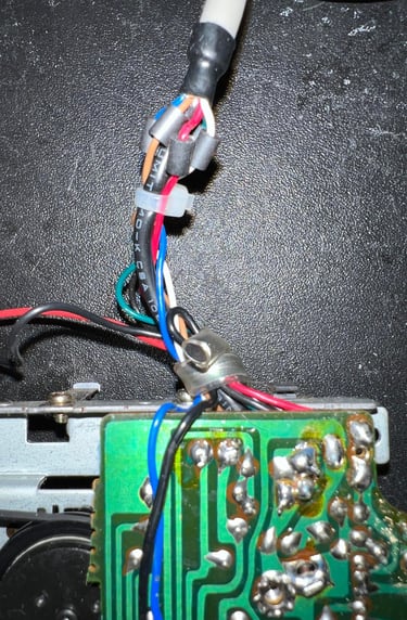
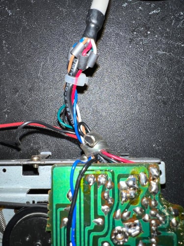
The cable looks to be undamaged and in general good condition - both from the outside and the inside (see pictures below). Also, the connector pins are in good condition and without any visible corrosion. The connectors are sprayed with contact spray nonetheless.
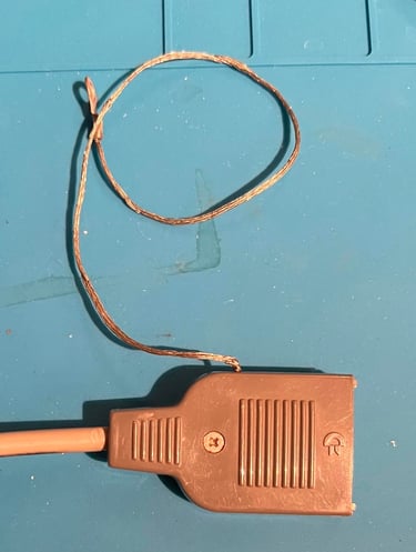
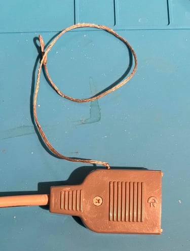
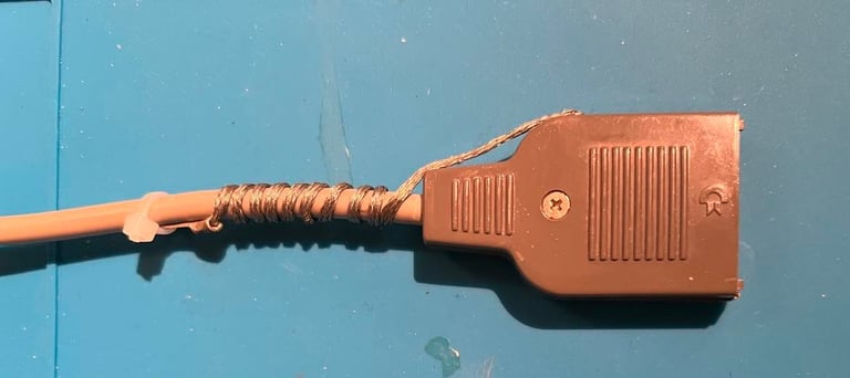
For historical reasons there is a ground wire attached to the datasette cable. But this ground wire is not used in operation with the Commodore 64. To avoid that this wire accidentally enter the user port (and creates a short circuit) the wire is twisted around the cable and fastened with a cable tie.

PCB and electrolytic capacitors
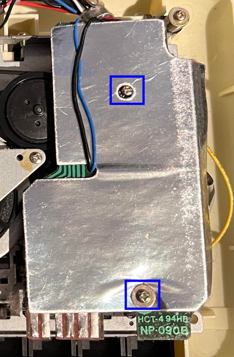
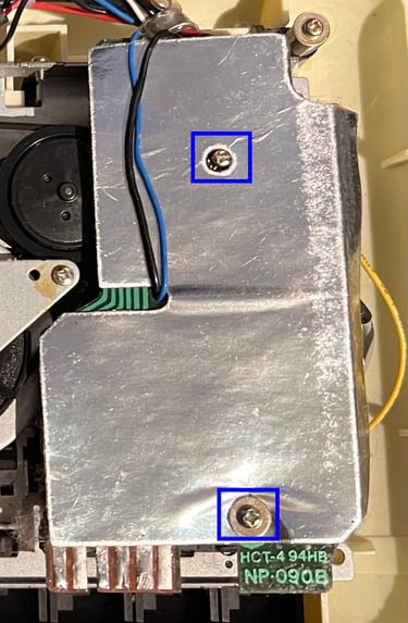
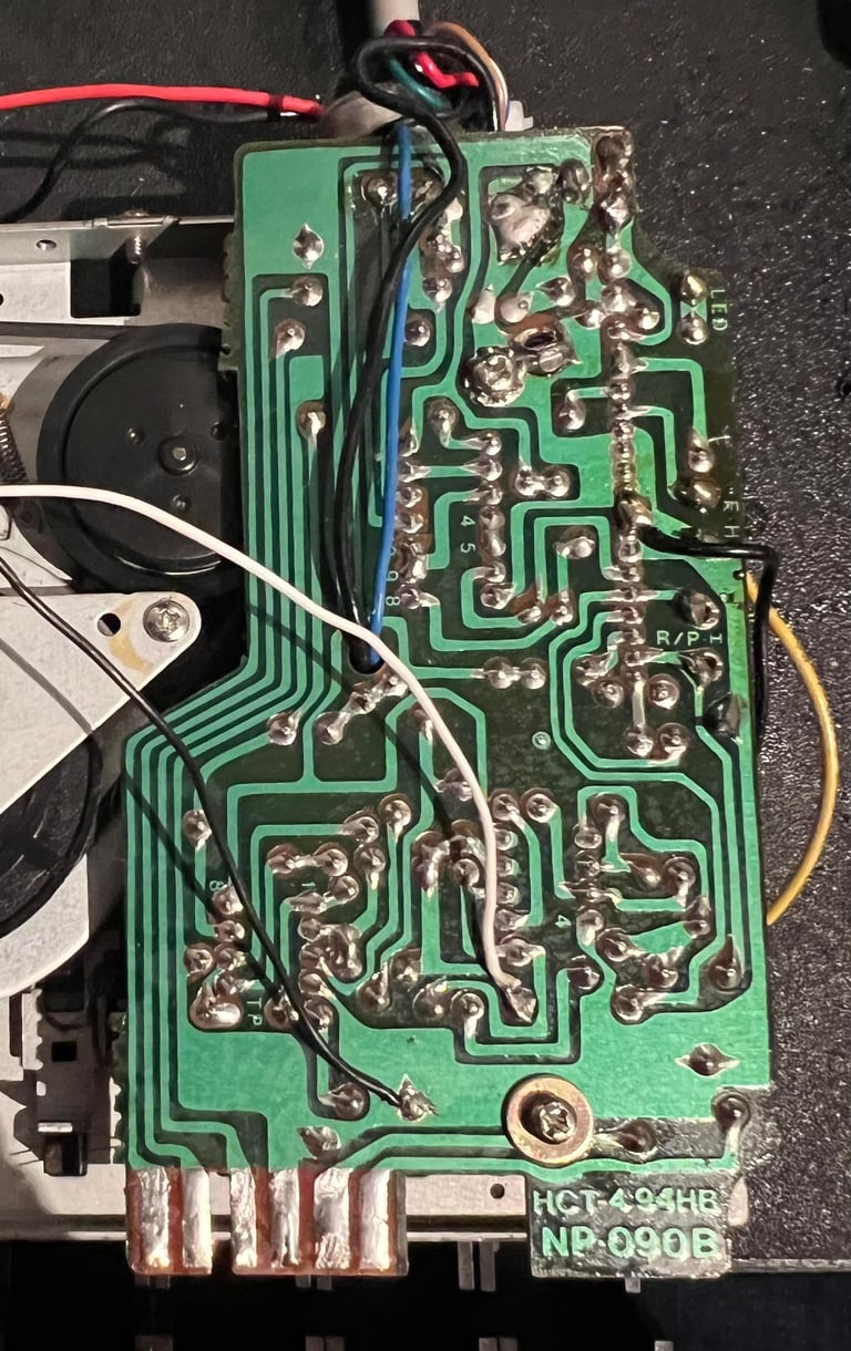
As can be seen from the picture below this is a "NP-090B" version of the PCB in datasette. To lift the PCB out of the chassis the two screws holding both the cardboard and the PCB itself are removed (blue squares) first.
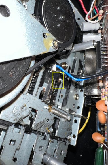
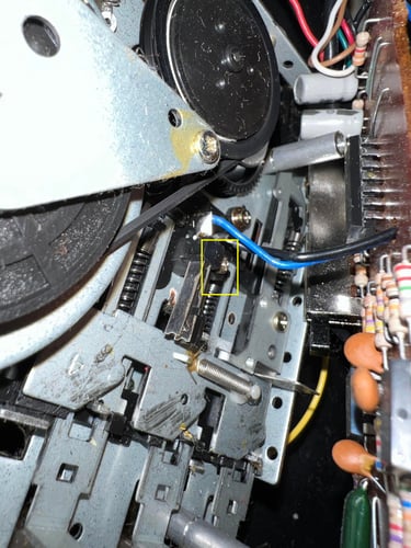
Before starting lifting the PCB off the chassis I open the cable strain. Wires are often soldered directly to the PCB on the datasette so it is a good idea to be careful when lifting off. NOTE: I write "starting" to lift off the PCB. There is a small leaf switch beneath the PCB which is attached with a small screw and two wires. This needs to be unscrewed. To do that I wiggle the wires so that I can lift the PCB halfway and then use a small screwdriver to remove the leaf switch. The yellow square in the picture below shows the position of the leaf switch.
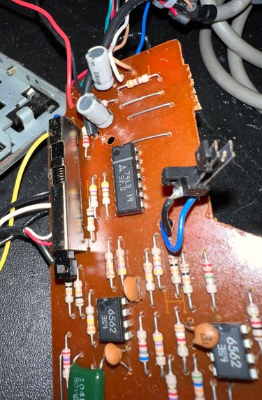
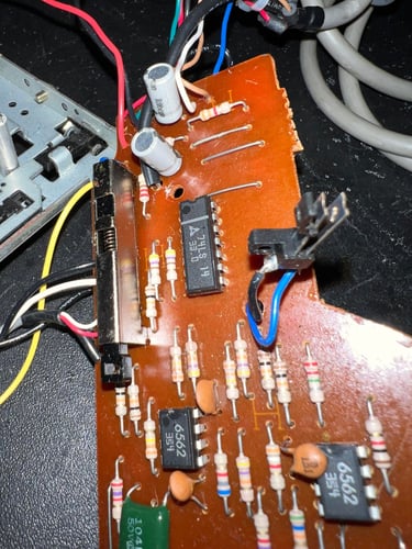
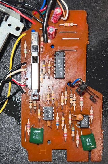
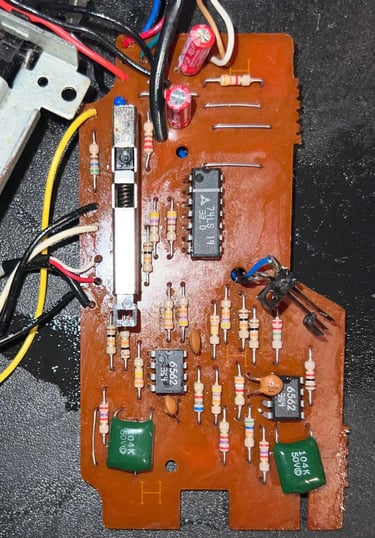
In the NP-090B PCB there are two 47 uF [10 V] electrolytic capacitors that will be replaced and there are two 6562 OP-Amps which I will use later when controlling (and potentially adjusting) the R/W head. The PCB looks to without any damage or corrosion, but I clean it with some isopropanol. Below are pictures of the PCB before and after replacements of caps and cleaning. I use quality capacitors from Wurth Electronics.
Replacing the belts
If you are to do only one refurbishing task - this is the one you will do. Replacing the belts are in my experience the most valuable operation. Even if the interior is dirty and the R/W head slightly misaligned new belts can do wonders. I get my datasette belts from DataServe-Retro (fast delivery and quality products for reasonable prices).
There are two belts in the datasette: one for the motor and flywheel and one for the counter. NOTE: when ordering new belts make sure you order the right version of the belts. In the 1530 C2N datasette it is common to distinguish between the "Made in Taiwan" and "Made in Japan" version. This is a Taiwan version.
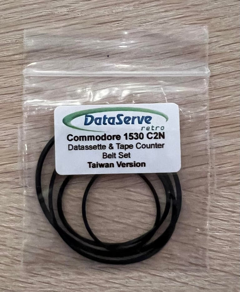
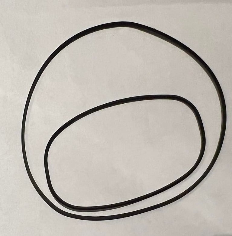
Installing the new belts is done in the reverse order as described in the "interior mechanics" part. Not too difficult as long as you don´t disassemble more than is strictly required. Below are pictures of the new motor- and counter belts.
The old belts were quite worn out - low flexibility and deformed.
R/W head alignment
For the datasette to operate flawless the read/write head needs to be properly aligned. Otherwise the horrible "?LOAD ERROR" will be a frequent message...
It is not always the case that the R/W needs to be aligned after 40 years. If it has never been aligned since production chances are that the R/W is positioned correctly, but quite often the R/W head has been adjusted several times during its lifespan. So to align the R/W head, or to verify that it is already ok, I use the method described in the HOWTO article "Datasette head alignment".
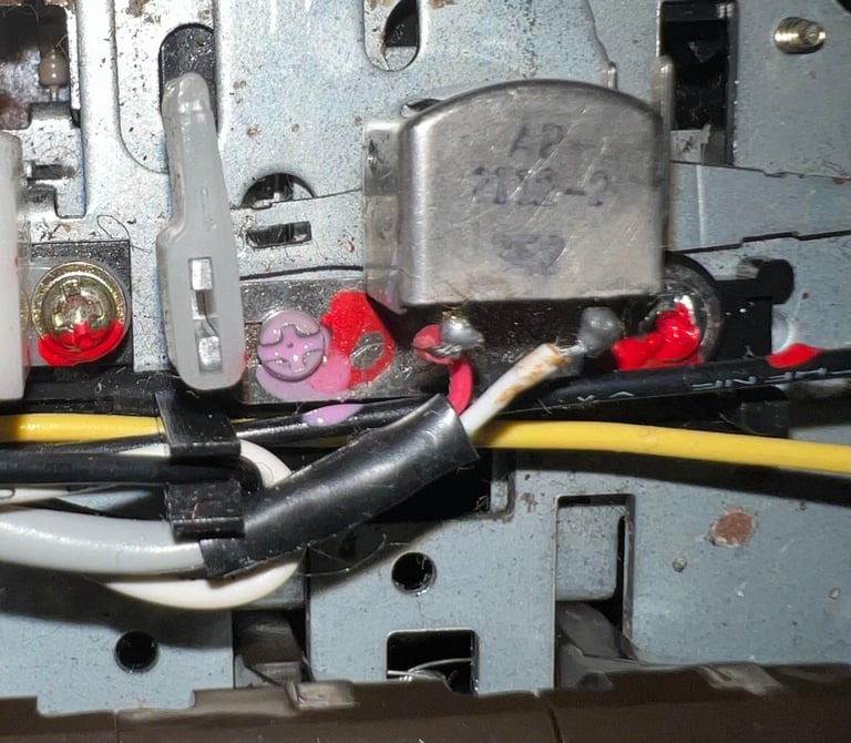
First step is to solder two wires on the PCB. One wire connected to the 2nd OPAmp output and one wire to ground where the description of these positions are described in the HOWTO article. See picture below.

Then the datasette is completely assembled with cover and screws while the cable and the two wires are sticking out of the casing. It is very important that the datasette is completely assembled while aligning the R/W head. If you align the R/W head without the casing your risk that the case itself will misalign the position of the cassette when used "for real".
The oscilloscope is connected to the two wires, and while a tape is played the R/W head is adjusted to maximum amplitude by adjusting the small screw. In the picture below the setup is shown.

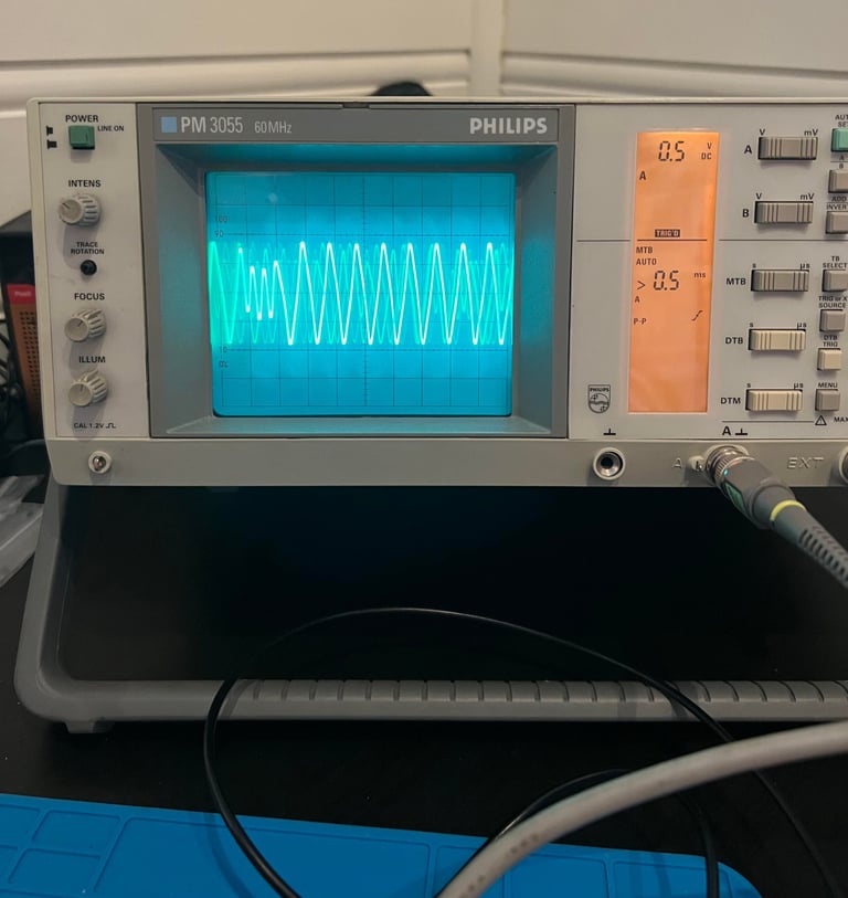

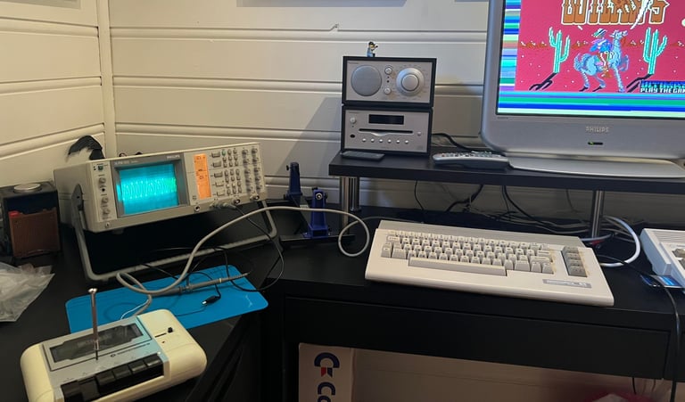
A short video from the adjustment process below where you can see the signal from "zero" to maximum amplitude.

Finally, after the maximum amplitude is reached the R/W head is "locked" in position by adding a small drop of nail polish (Chanel borrowed from my daughter!).

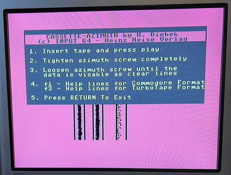
The result of the adjustment is verified by using the cassette-azimuth software on a Commodore 64 while an original tape is running. The result we are looking for are three lines within the vertical bars - which we now get. See picture below.
Testing
Playback
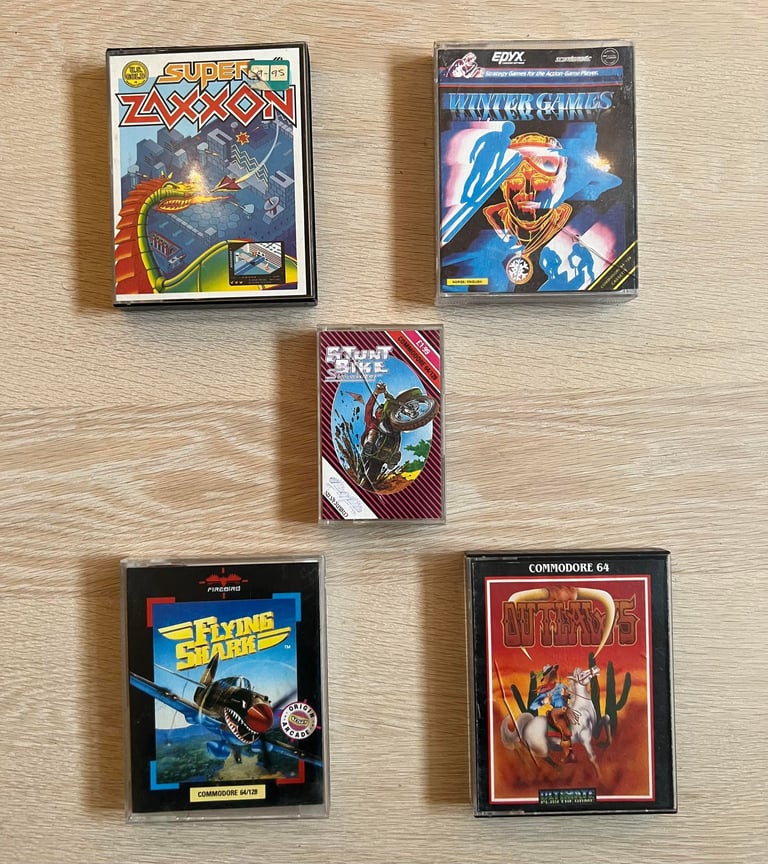
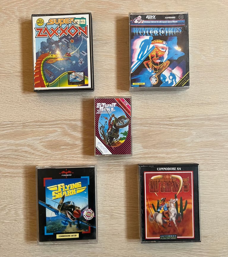
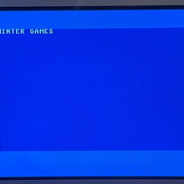
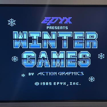
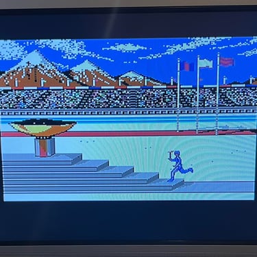
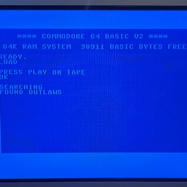
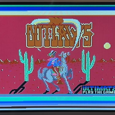
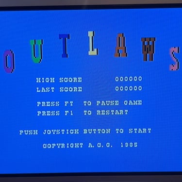
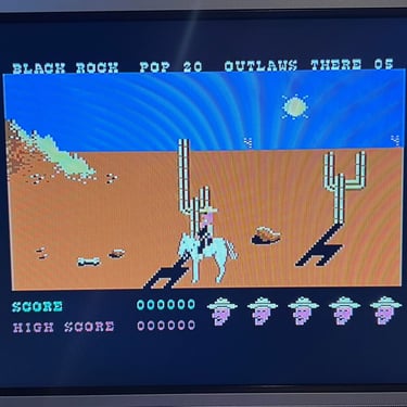
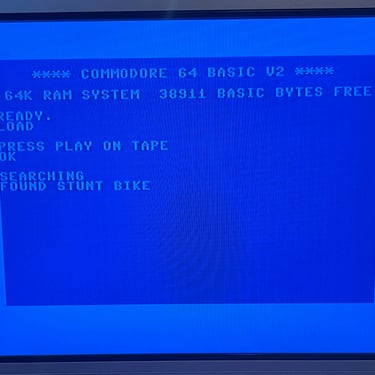
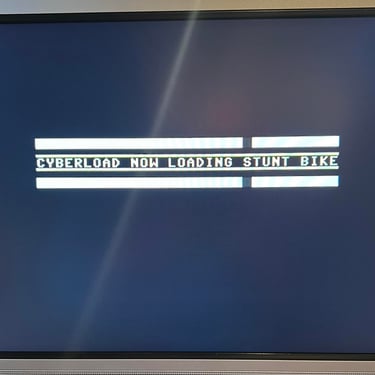
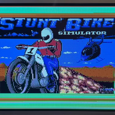
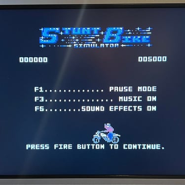
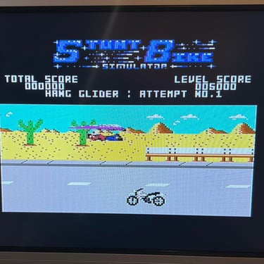
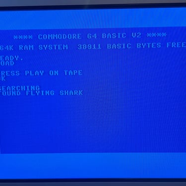
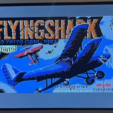
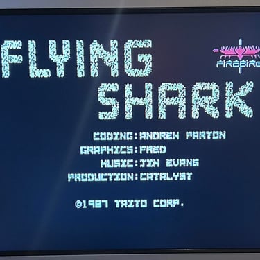
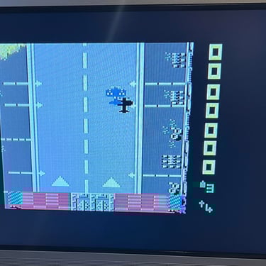
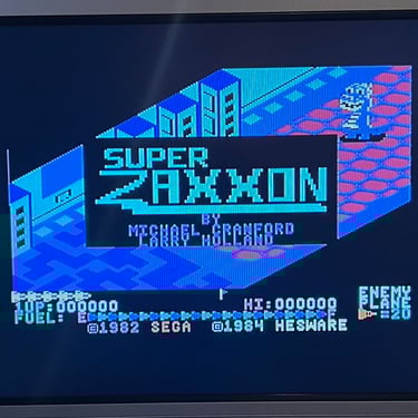
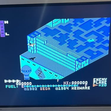
To make sure now works as it should I select five original C64 games to be used for testing. Even if these games are old and worn the load without any problems at all. Below is a picture gallery from the testing.
Recording
The saving functionality is also checked and verified. A small BASIC program is made and the SAVE command is used (and then the program is re-loaded). The LED is also on while recording is in progress.

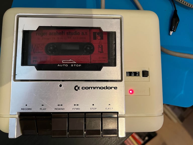
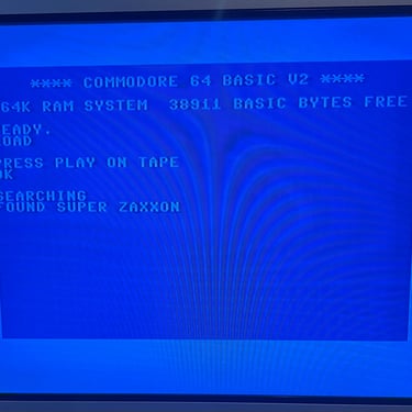
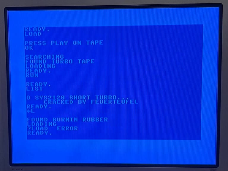
Mystery tape
Is there something on the mystery tape?! Well... yes and no. There is "TURBO TAPE" which loads without any problems. Using the famous "->L" command then starts loading "BURNIN RUBBER", but it ends in a sad "?LOAD ERROR". Maybe there are more games on this tape, but I will leave that for the next owner to find out...

Final result
"A picture worth a thousand words"
Below is a collection of the final result from the refurbishment of this datasette. Hope you like it! Click to enlarge!

Banner picture credits: Evan-Amos