

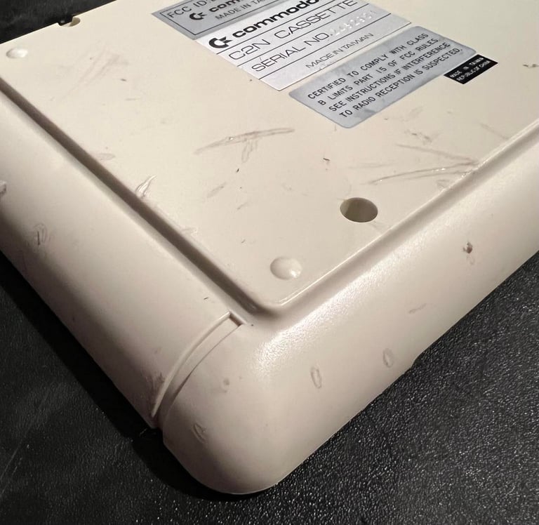
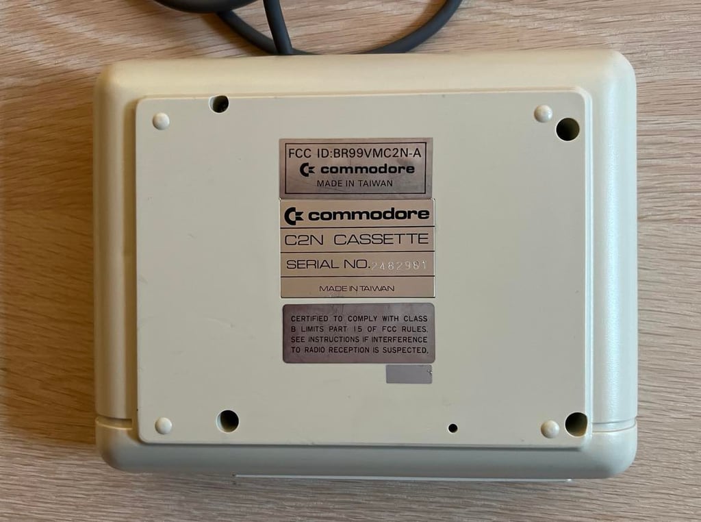
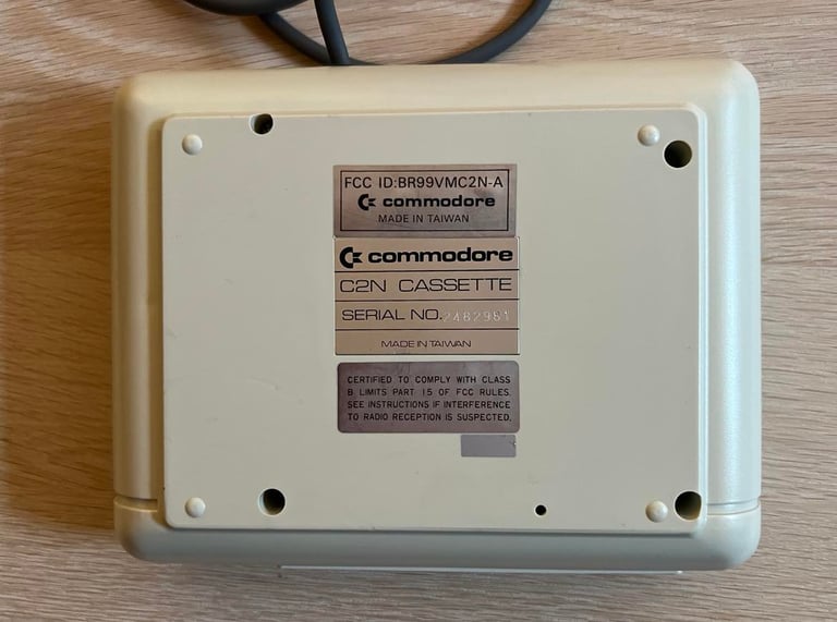
1530 (C2N)
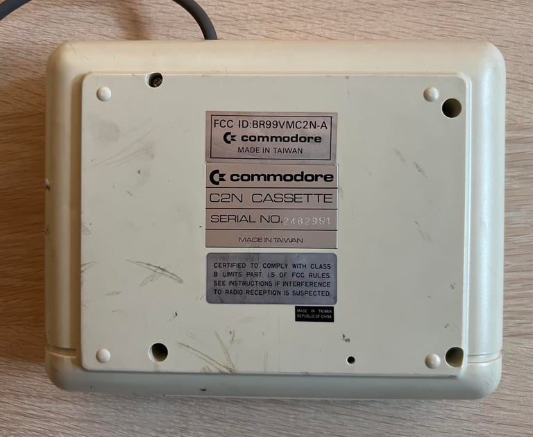
Ser. No. 2482981
Starting point
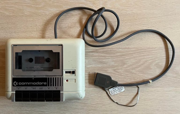
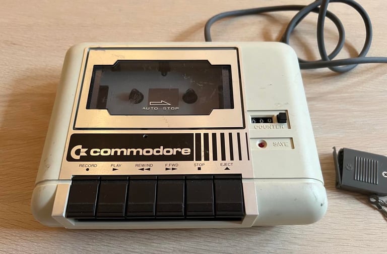
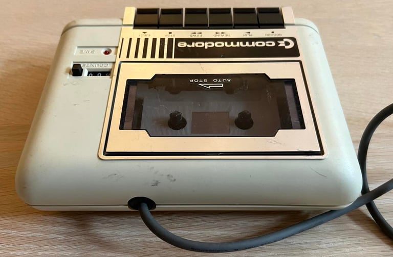
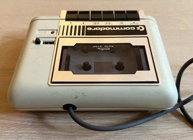
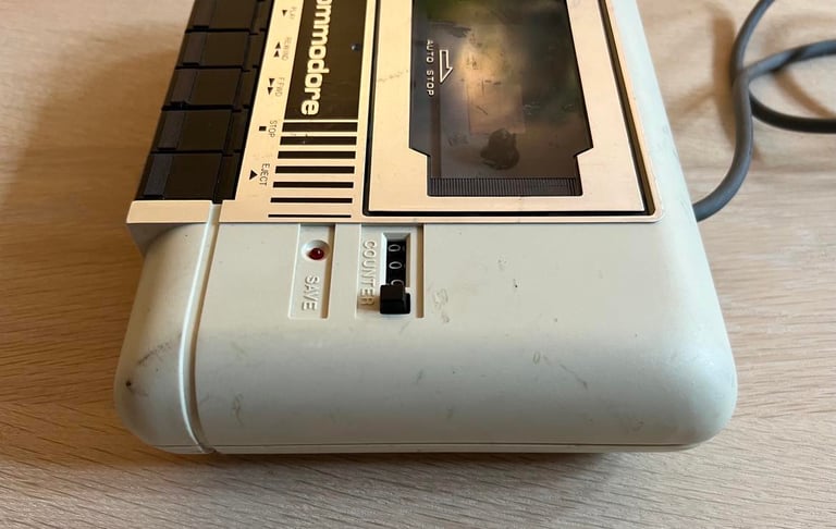
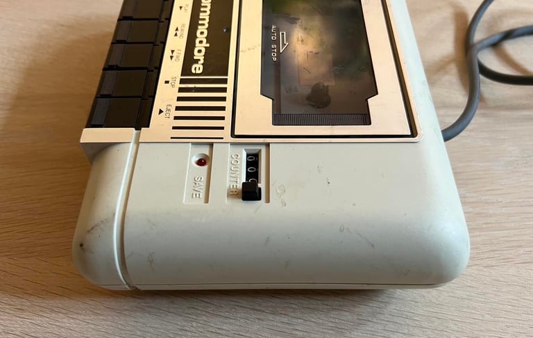
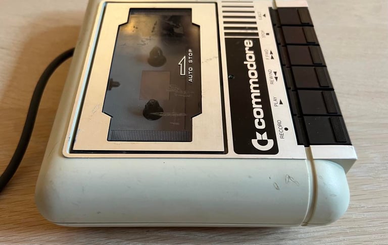
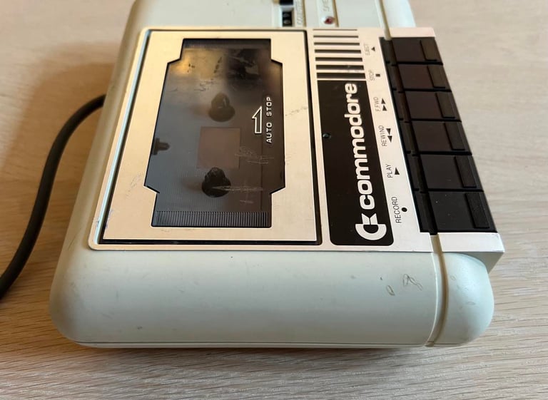
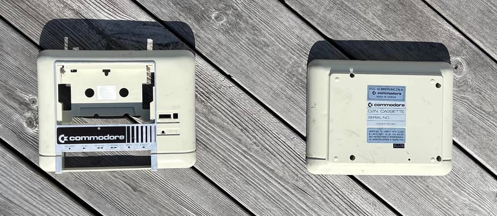
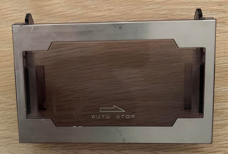
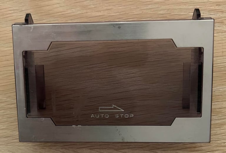
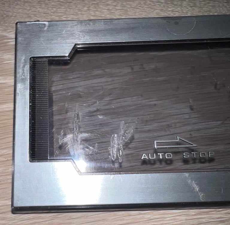
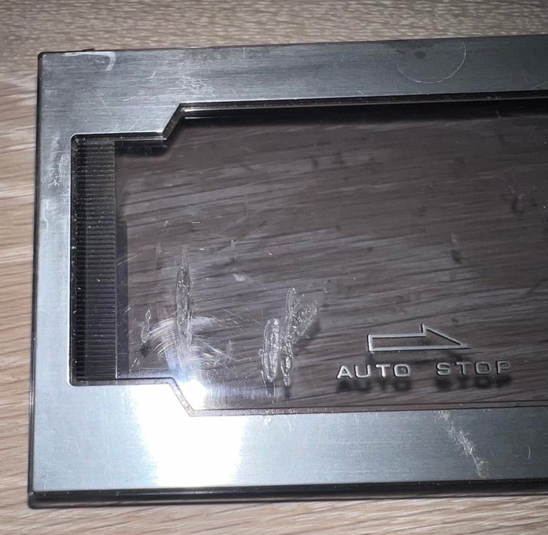
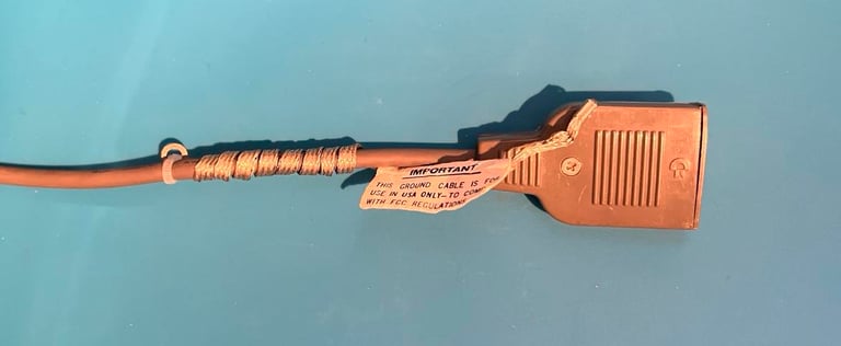
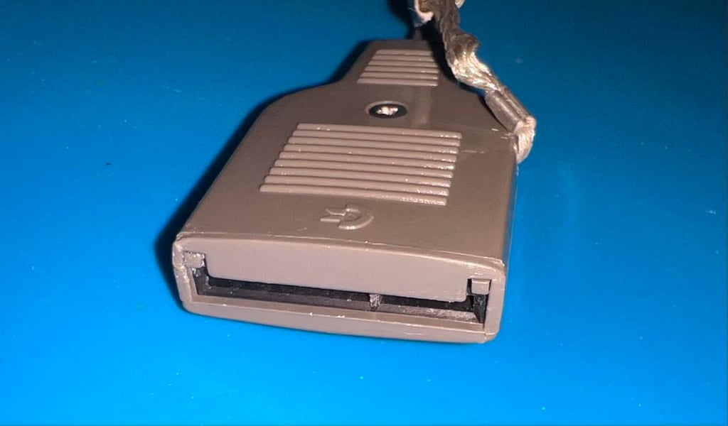
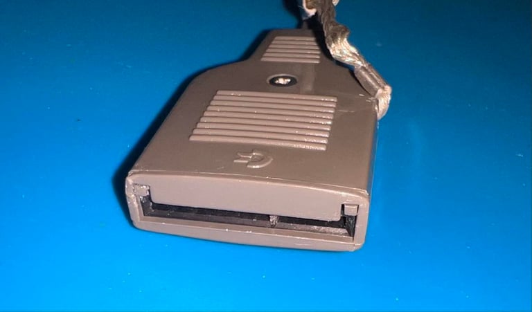
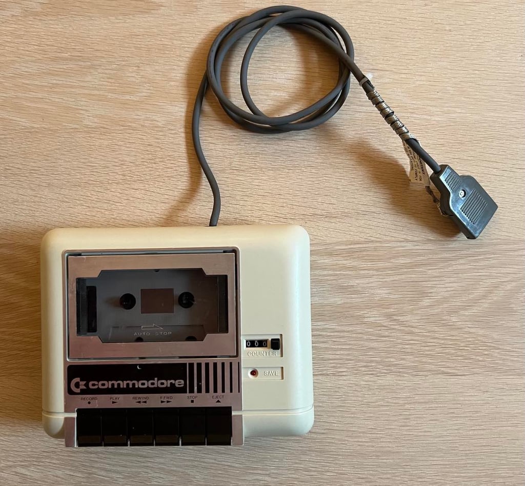
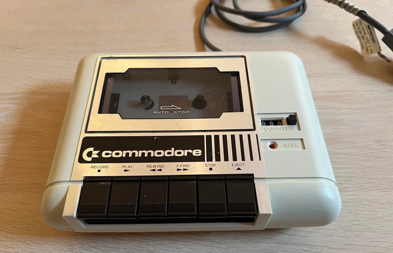
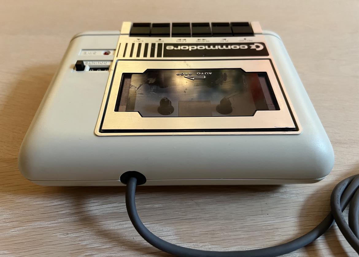
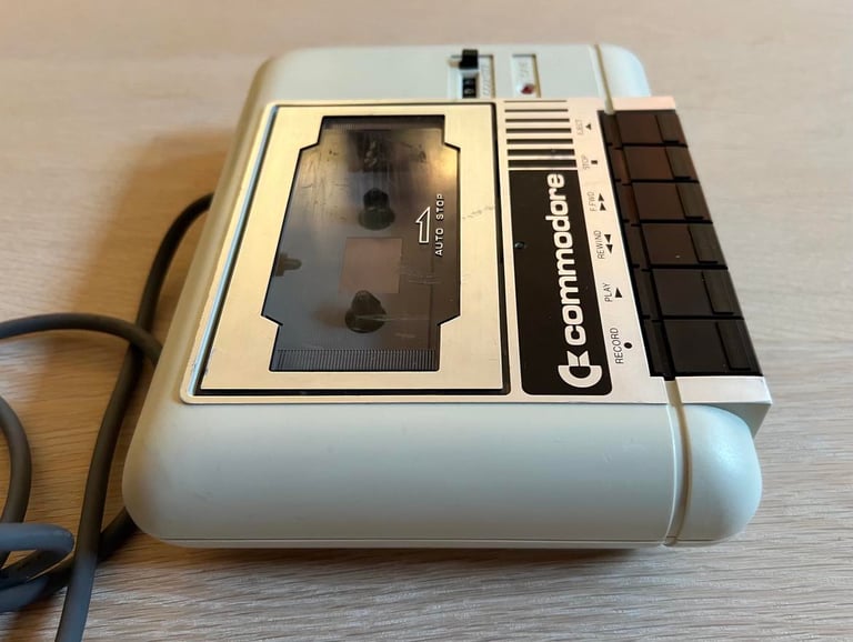
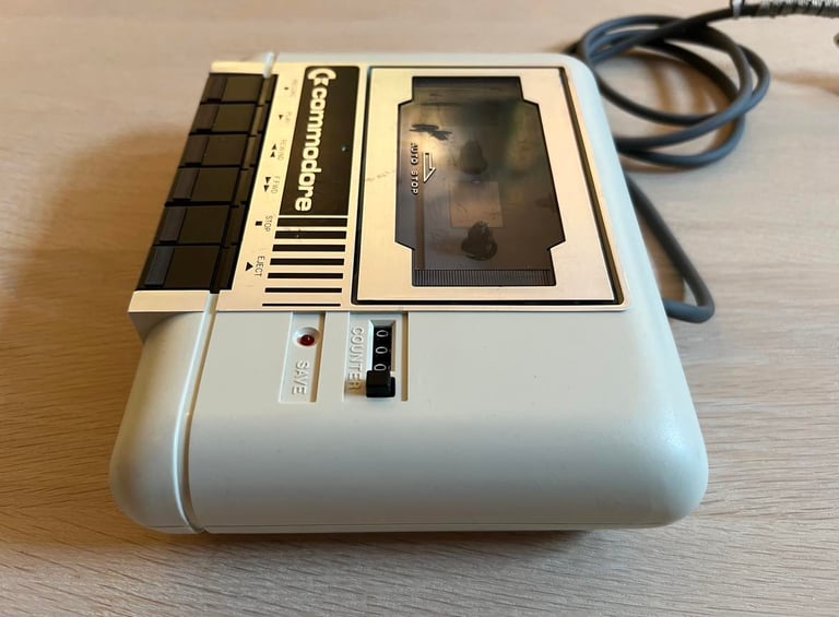
This datasette doesn´t look very good from an aesthetic perspective. It is full of marks, from dirt and also "cable burns" - specially on the backside. The cable plastic connector housing is a bit broken. But besides that the datasette seems to be ok - seen from the outside. I can not see any major damage to it, but at the time of writing I have no idea if this works at all.
Below are some pictures of the datasette before refurbishment.


Refurbishment plan
To refurbish this 1530 datasette the plan is to:
- Clean and remove stains from exterior casing
- Clean the interior mechanics
- Check cable and replace strain relief
- Check PCB for corrosion and replace old electrolytic capacitors
- Replace motor- and counter belts
- Check, and if necessary, adjust R/W head for optimal tape reading
- Check, and if necessary, adjust motor speed for optimal tape reading
- Verify datasette operation by testing
Note that these steps are not necessarily done in the order described above, and several of these steps are done in parallell.
Exterior casing
Cover
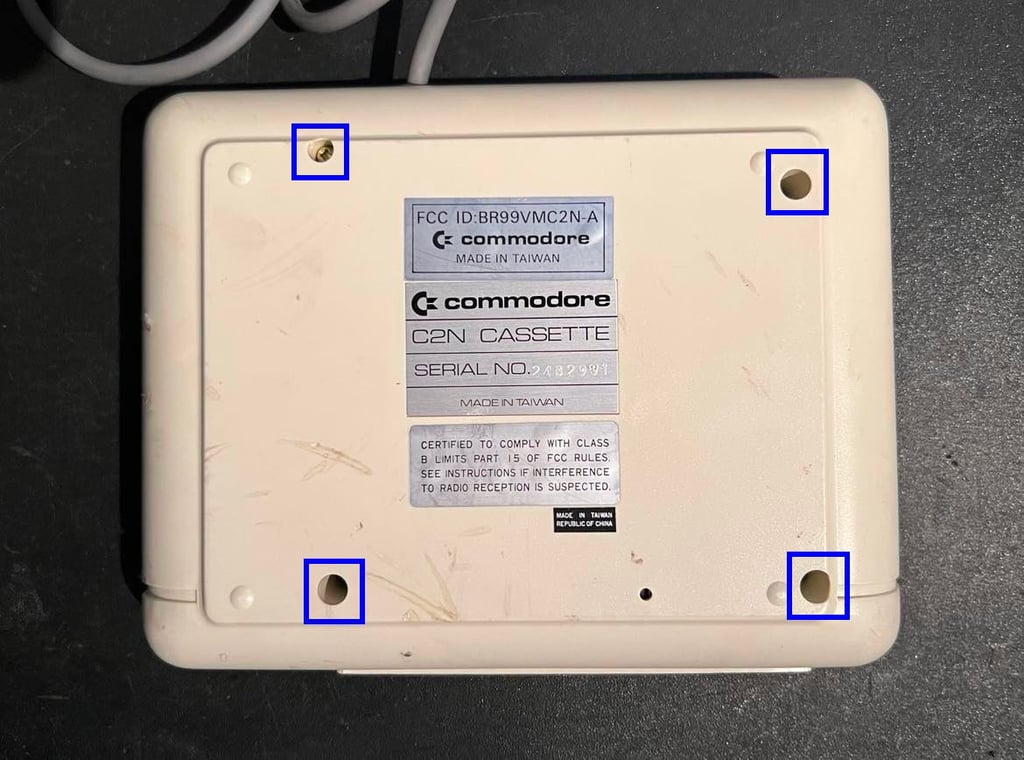
It will require a lot of work including cleaning and sanding to get this datasette in a presentable state. But first, the casing needs to be disassembled. It consists of a top- and bottom cover which are held together with four screws at the bottom. See picture below (blue squares).

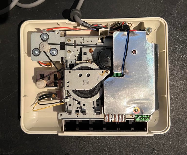
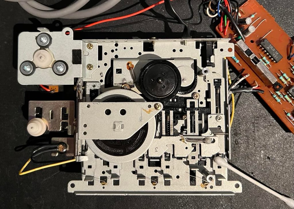
Removing the bottom cover reveals the backside of interior. First impression is good - I can not see any damage and the amount of dust is surprisingly little.

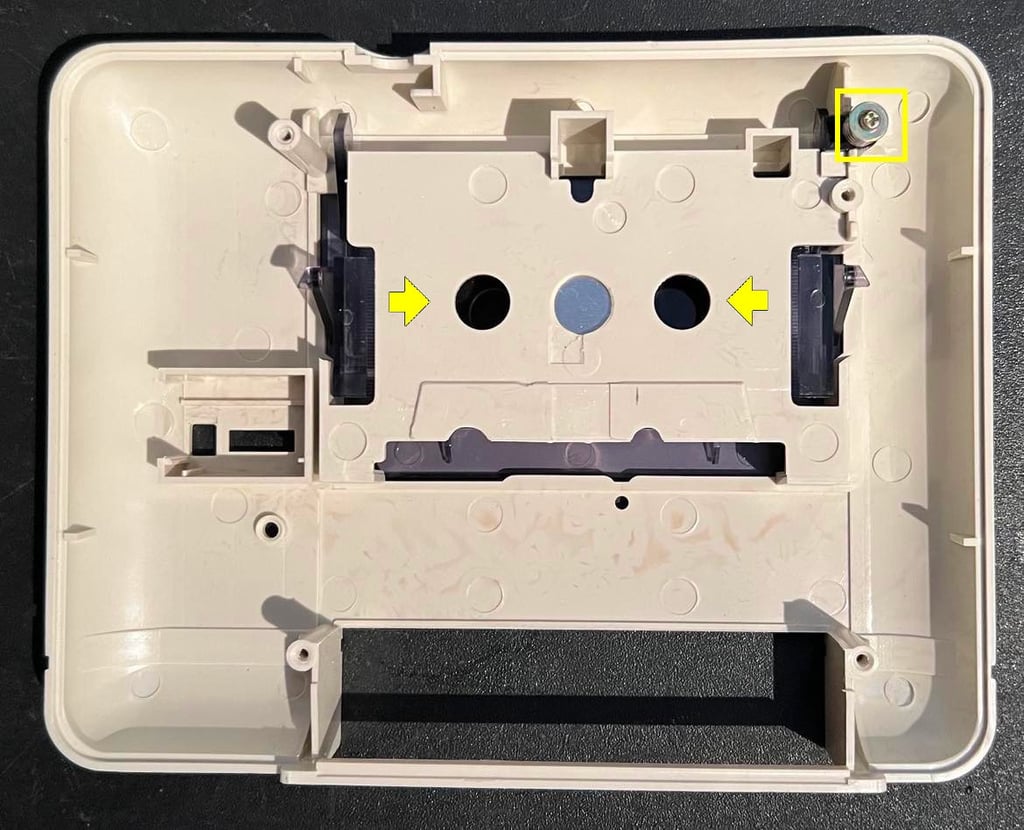
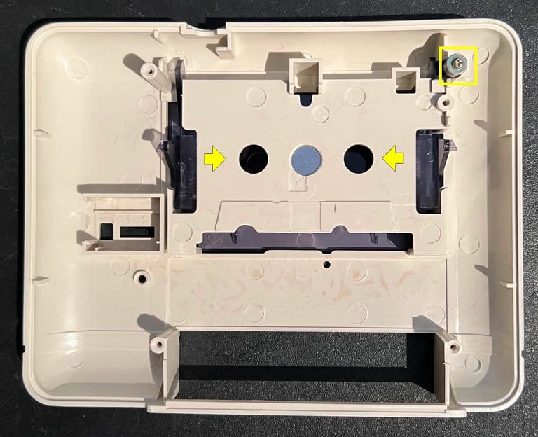
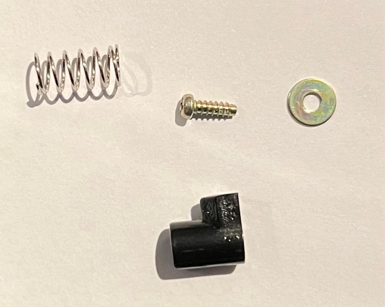
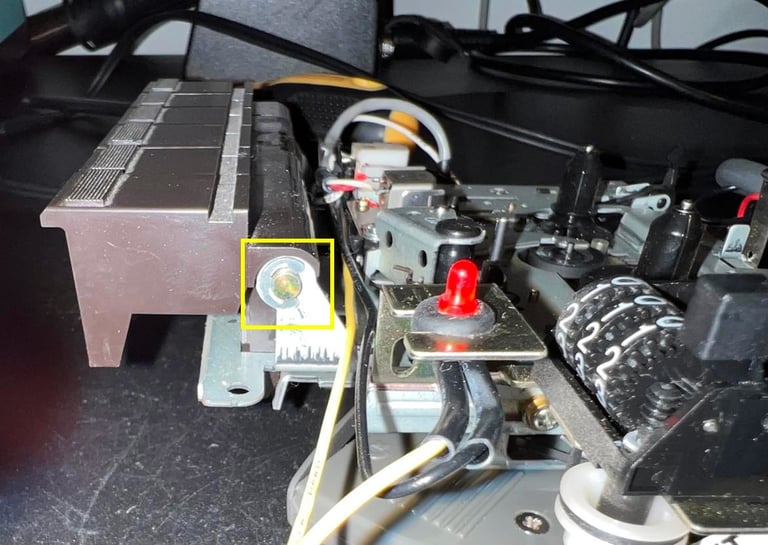
The interior is simply lifted and the top cover is exposed. The screw, spacer, spring and plastic clip is removed (yellow square) and the tape lid is removed by gently pushing the two plastic hinges inwards (yellow arrows).

The top- and bottom cover is cleaned a bit (not completely) and left outside in the sun for a few days. It is not too often the sun is shining in Stavanger, but I manage to get 4-5 days with some sunbrighting.

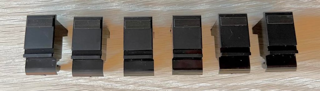
Keys
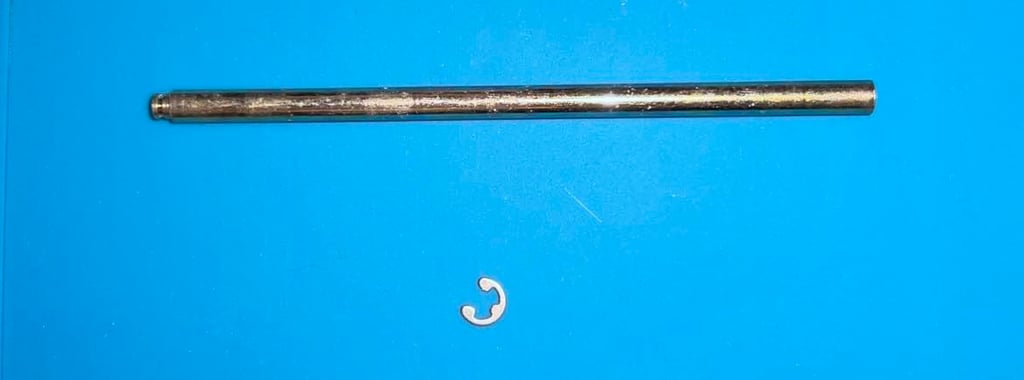
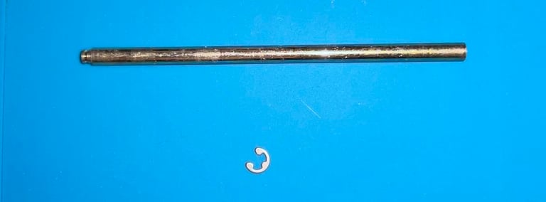
To remove the six keys the E-clip is removed from the shaft holding the keys (yellow square), and the shaft is pulled out.

The interior is flipped upside down, and the keys are removed. To remove the keys the small springs are carefully removed from the small notch in each key. Quite often the whole spring is easily removed, but on this datasette these springs are actually fastened which is good.

All the keys are cleaned individually with mild soap water and glass cleaning spray. The result is very good.

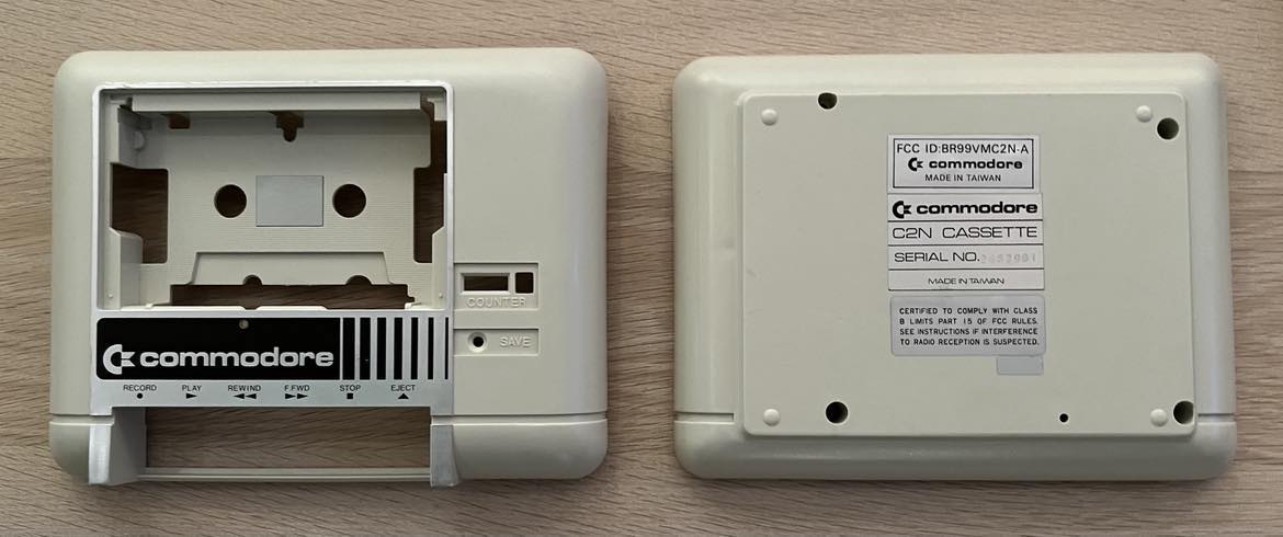
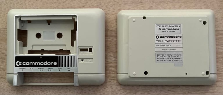
The top- and bottom cover are cleaned with plenty of isopropanol and rinsed with Q-tips. And most of the marks are gone - without sanding. Just hard work cleaning. Nevertheless, there are still some marks on the tape lid which I can not remove. But all in all I am quite satisfied with the result. Below are some "before" and "after" pictures. Note how the cable marks are more or less gone.

Interior mechanics
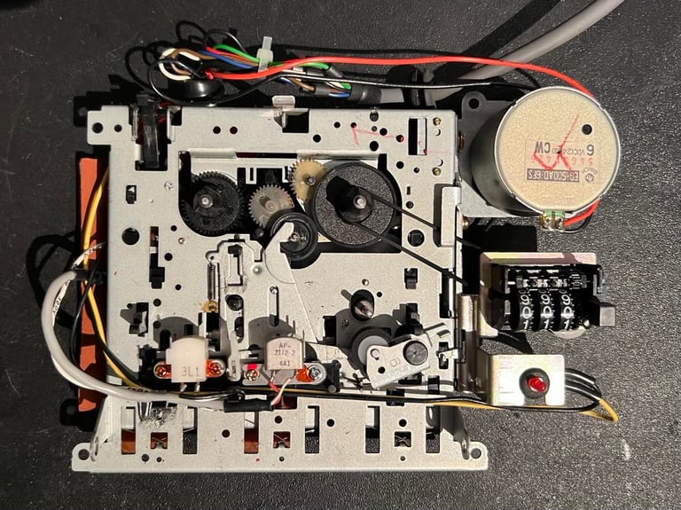
Initial cleaning and inspection
The interior seems to be in very good condition. It needs to be cleaned, but the corrosion is marginal and no sign of any damage. And now it occurs to me... I have partly refurbished this datasette long ago. So the datasette is partly cleaned already and both the counter- and motor belts are replaced. Nice!
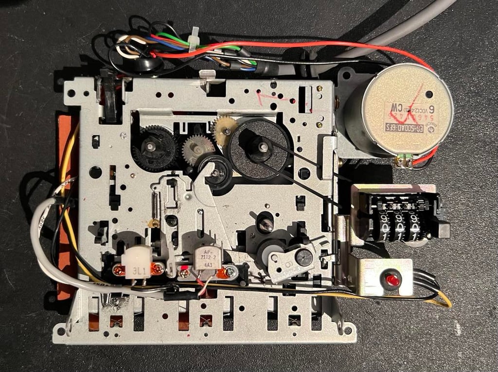

Even if the counter- and motor belts are new they are removed temporarily before cleaning. Removing the counter belt is easy - only lift the small hinge and pull the belt off. See picture below.
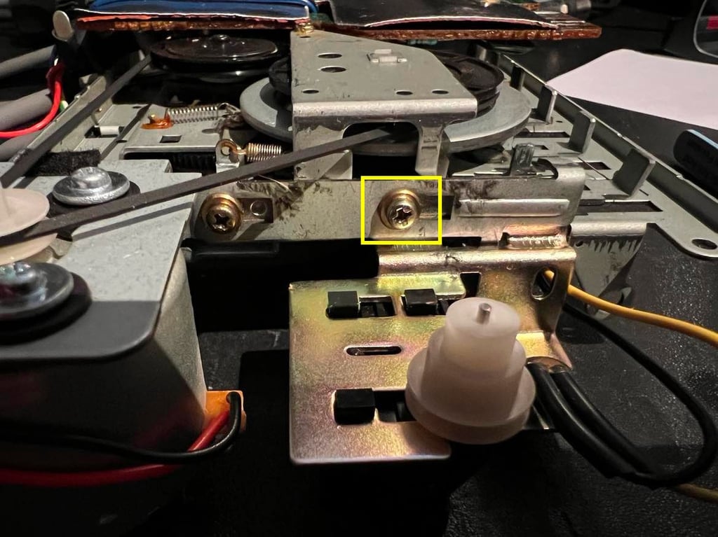
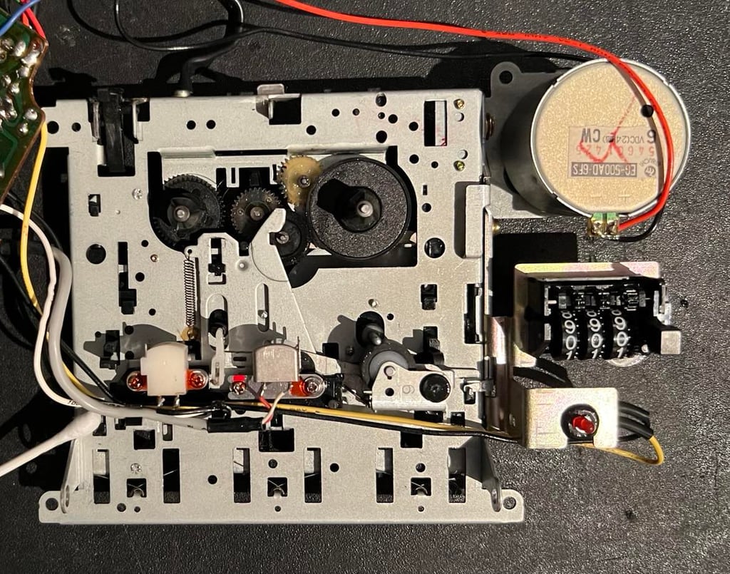
To remove the motor belt is somewhat more complicated. Not that it is difficult in any way, but if you remove too many of the screws it can be tricky to assemble it again. First, the center screw on the side is completely removed (yellow square in picture below).

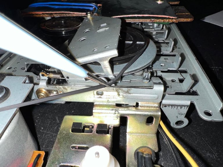
Then the screw holding the flywheel is partly removed - just so that the metal lid can be slightly lifted.

With a pair of tweezers the motor belt is carefully moved out of the small notch in the metal lid. The belt is then removed completely from the flywheel and pully.

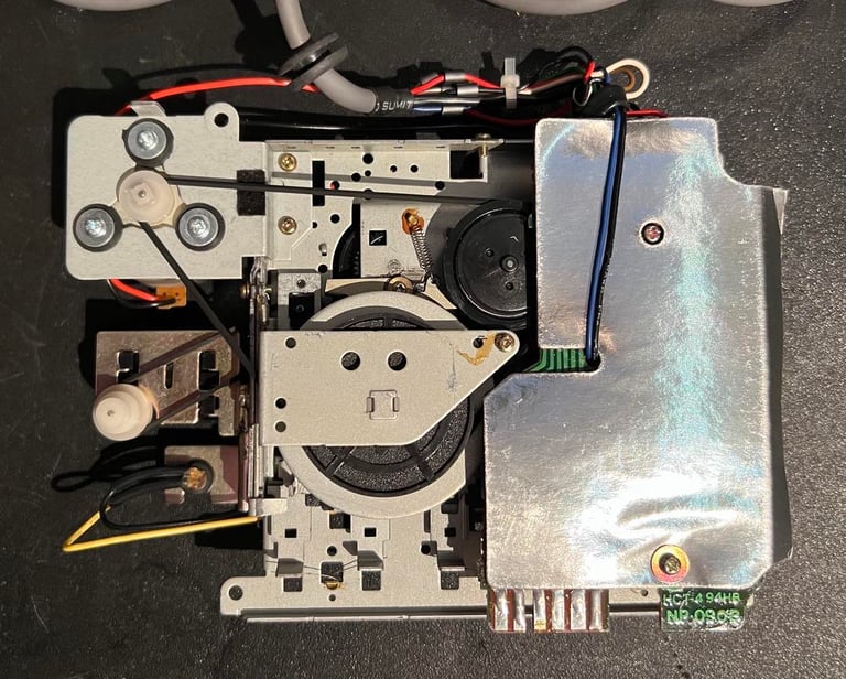
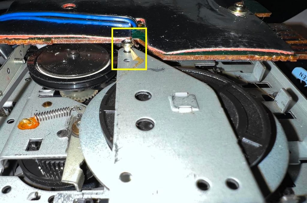
Next step is to partly remove the PCB. First, the cardboard shield over the PCB is removed. There is a small screw with a space close to the bottom of the cardboard (yellow square).
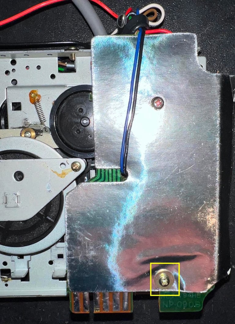

Removing the cardboard reveals a very dirty PCB, but I will clean that later. Now the second screw is removed (yellow square) and the cable ties are cut / loosened.
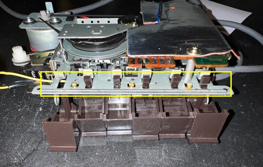
The PCB is then partially lifted - just enough to access the small leaf switch beneath the PCB (yellow square). With a small screwdriver the leaf switch is removed and the PCB can be lifted away from rest of the interior.

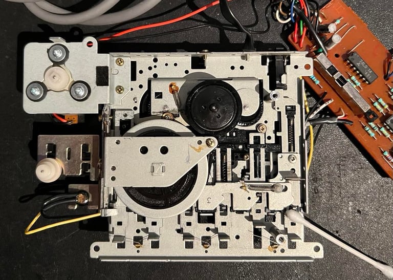
Both the front and back of the interior mechanics are cleaned properly with isopropanol. Some moving parts (not near the rubber belts or gears) are lubricated with a small amount of MoS2 grease. The counter is lubricated with some silicone spray.

Cleaning the R/W head
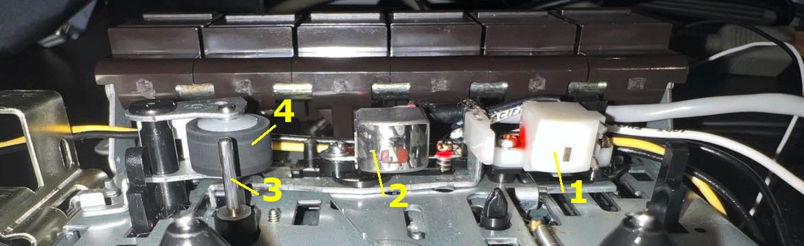
A prerequisite for the datasette to operate flawless is to make sure the erase (1) - and read/write (RW) (2) head, capstan (4) and pinch roller (3) are clean and without any kind of damage. It is good practice to clean these parts (together with rotating parts) after the initial cleaning and when the datasette are partly re-assembled again (keys and belts). Pinch roller, capstan and gears can now be cleaned while they are rotating. Below is a picture of the critical components after cleaning.

An example of how the capstan and pinch roller is cleaned can be seen in the small video below (from another datasette - but the method is the same).


Cable
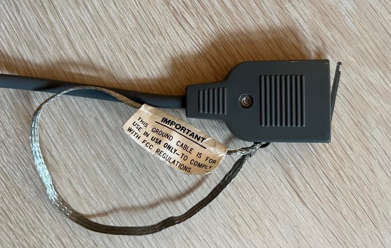
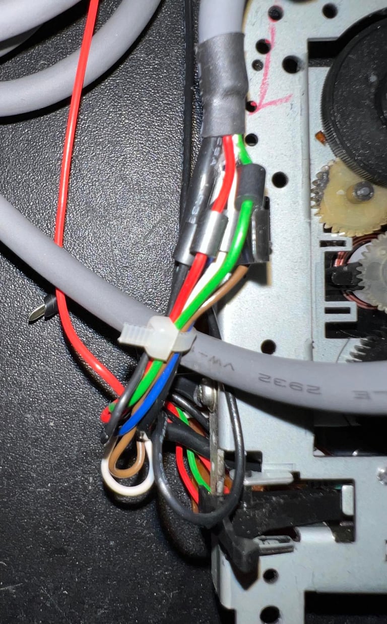
The cable connector is disassembled and checked. All wires and contacts are in good condition, but a part of the plastic casing is broken.
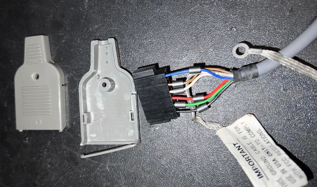
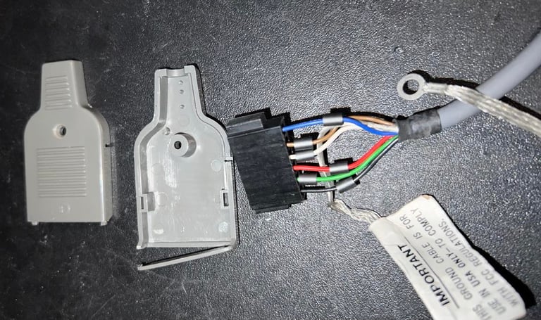
It is common for 1530 C2N datasettes to have a ground wire - which is not used. This ground wire is legacy from the PET area (and from old FCC regulations in the US). Nevertheless, the ground wire represents a danger. If by accident the wire enters the user port it can short circuit the Commodore 64. Therefore the ground wire is twisted around the cable and fastened with a cable tie. I find this better instead of cutting away the whole wire.

The broken plastic is glued back with some super glue. It could also be just cut and removed (and still work as it should), but I like to try to keep it as original as possible.
PCB and electrolytic capacitors
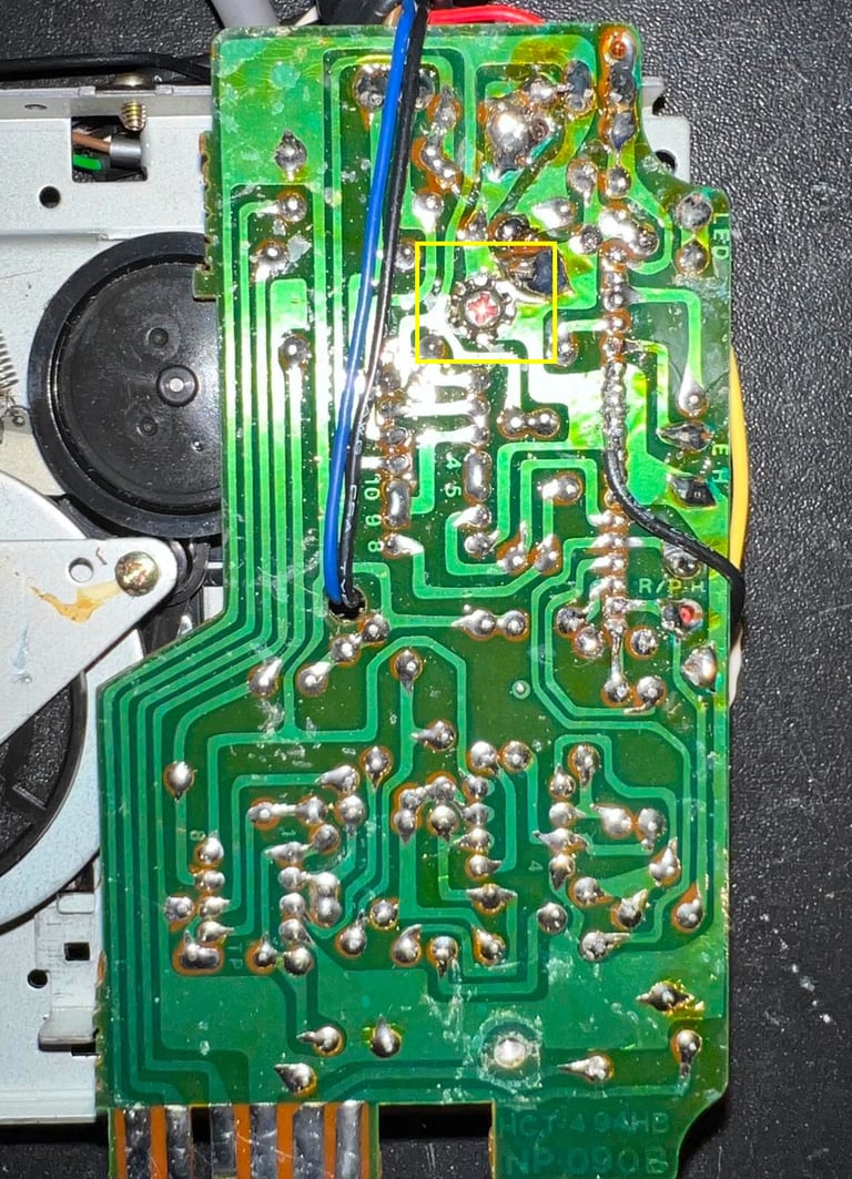
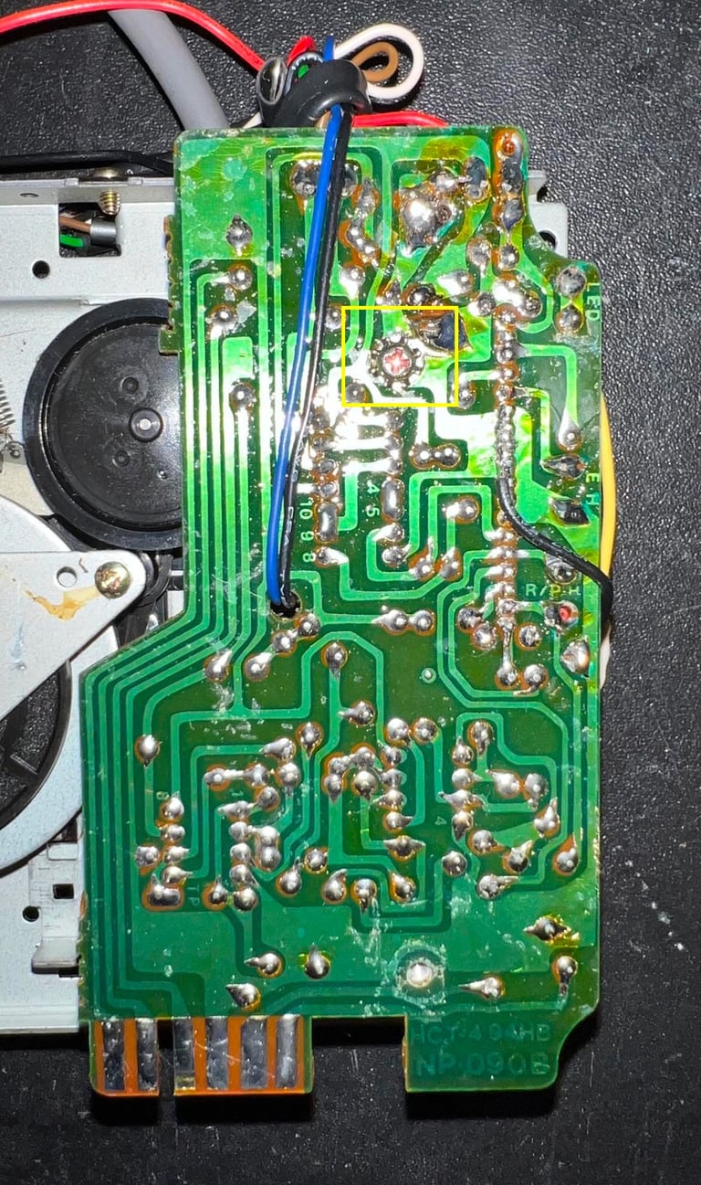
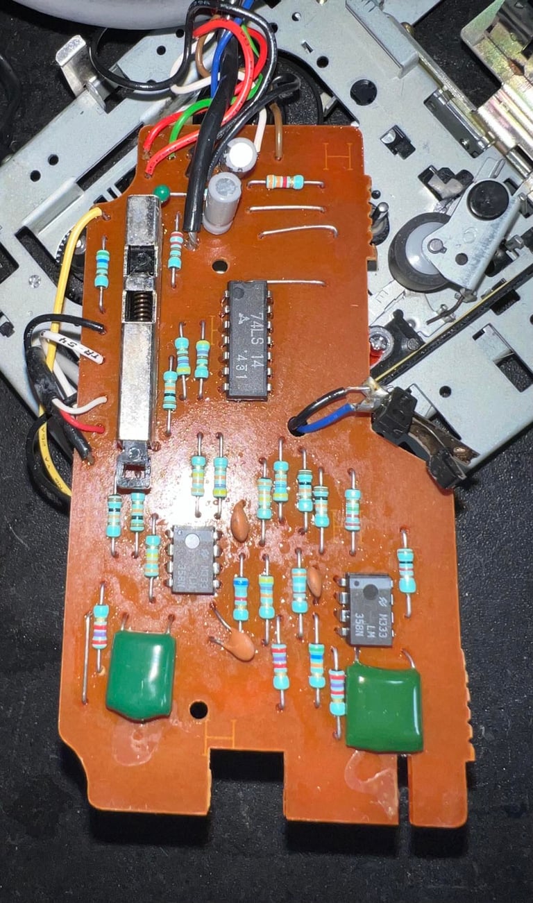
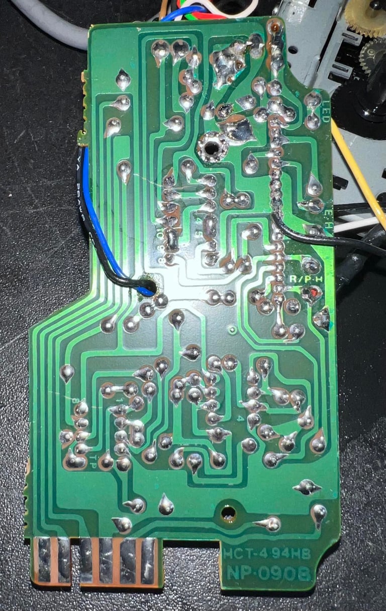
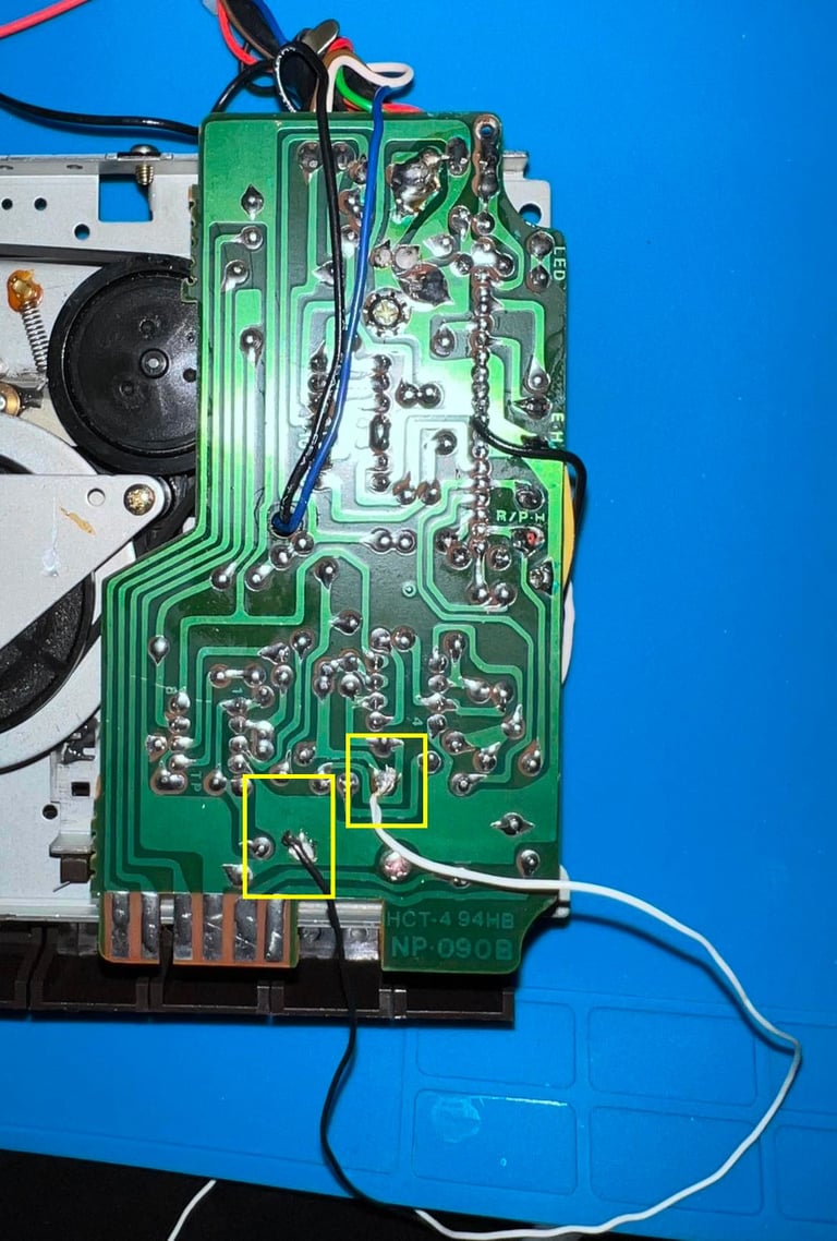
The PCB is marked "HCT-4 94HB / NP-090B". According to the capacitor list there are two 47 uF [10 V] electrolytic capacitors on this PCB. As seen in the "Interior mechanics" section the PCB was very dirty. Full of dirt and old flux residue. But nevertheless, the PCB looks to be in good condition. There are no sign of corrosion or damage.
Both the front and back of the PCB are cleaned thoroughly with isopropanol. Below are some pictures of the PCB after cleaning.

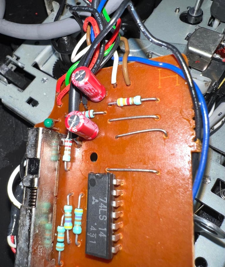
The two electrolytic capacitors are replaced with quality capacitors from Wurth Electronics. Also, the leaf switch is refurbished with a glass fibre brush and cleaned with isopropanol. Below are pictures of the new capacitors and the refurbished leaf switch.


R/W head alignment
In addition to replacing the belts it is crucial to check the read/write (R/W) head alignment and if necessary adjust it. Otherwise the datasette can´t load our beloved tapes without the notorious "?LOAD ERROR" or simply just fails loading.
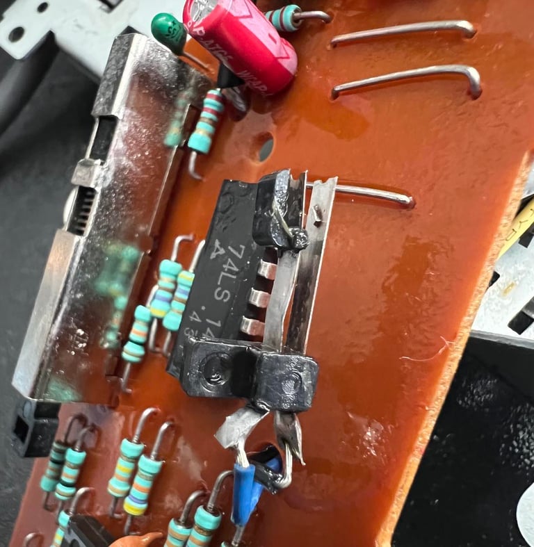
A detailed article about how I align the R/W head can be found here. As seen in this article I use both an oscilloscope and C64 software to do this operation in two stages; in the first stage I solder on two wires after the 2nd OP-AMP stage, connect the oscilloscope to these wires and then adjust the R/W head until I find the maximum amplitude on the oscilloscope. Second stage I use cassette-azimuth software running on a Commodore 64 while loading games from tape. In this second stage I do not do any adjustments - I only validate that the adjustment done in the first stage is correct.
Stage 1 - Aligning the R/W head with the oscilloscope
The oscilloscope is connected to the two wires soldered to the PCB as shown in the article and in the picture below.
It is very important that the datasette is completely assembled when connecting the oscilloscope and doing the alignment - with the tape lid and all four screws. If the datasette is aligned with the tape lid removed there is a significant risk that the R/W will be "misaligned" when the datasette is completely assembled. The datasette is loaded with the "Audio calibration tape" and, while running, the R/W head is adjusted with a small screw driver until maximum amplitude is found. Below is a small video of the R/W head alignment.

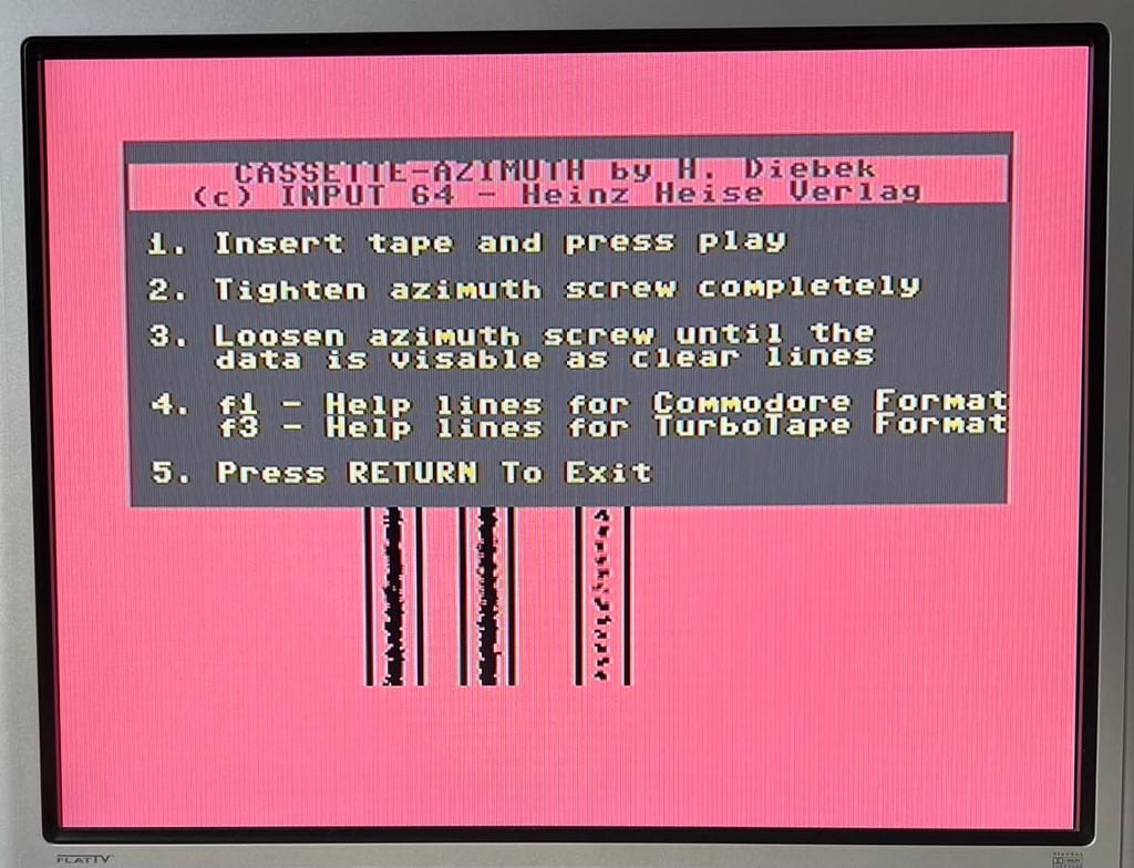
Stage 2 - Verification of the adjustment
To verify the adjustment with a second tool I use the cassette-azimuth software running on a Commodore 64. When the tape is loading there should appear three vertical bars on the screen. And the goal is that these three lines are as "solid" as possible. Note that these lines will never be completely solid, but the goal is that they are more or less straight vertical lines. If you have a misaligned R/W these lines will be scattered all over the screen.

To lock the align screw to its current position a small drop of (transparent) nail polish is used over the screw head. It is not so easy to detect in the picture below, but it is there.

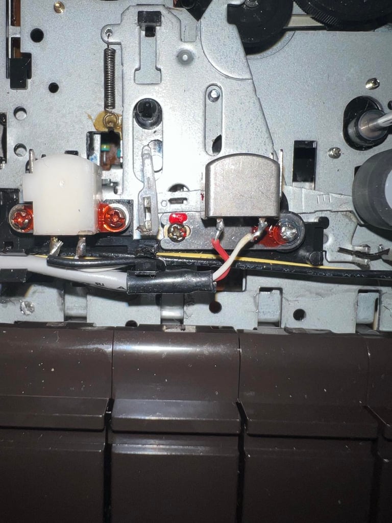
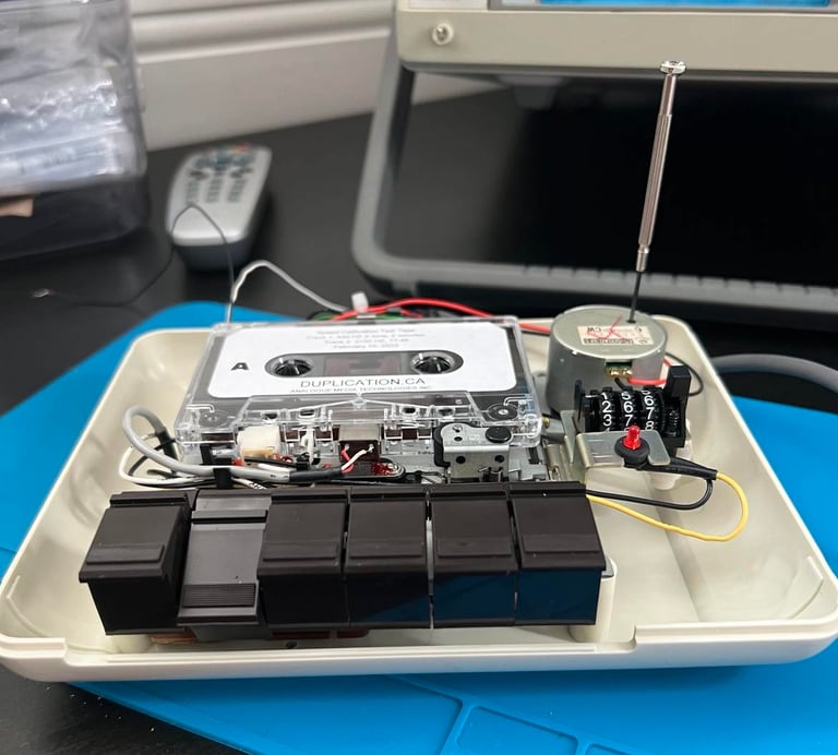
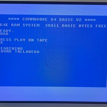
Calibrating tape speed
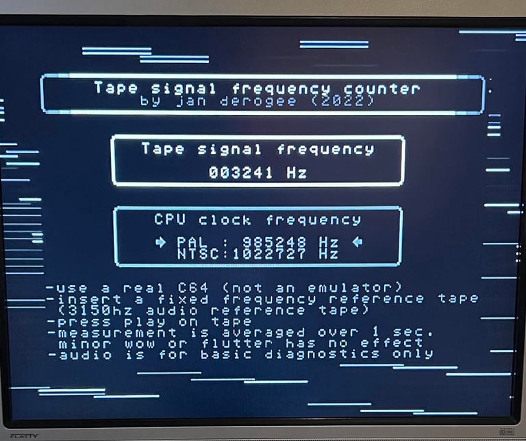
There is a first time for everything; calibrating the tape speed. I have never done this before, so this can be a success or a disaster. Based on a magnificent article by Jan Derogee and his Tape Frequency Counter software I will try to adjust the tape speed to optimal playback.
The idea is smart, but simple:
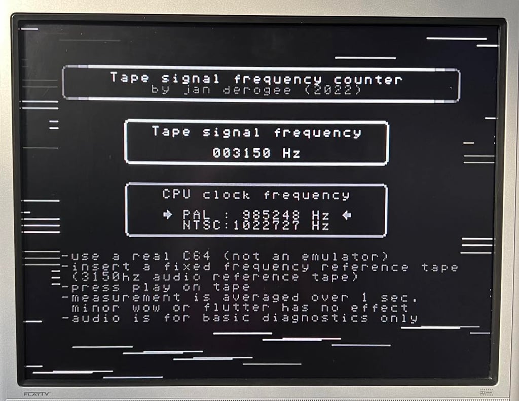
A professional Speed Calibration Audio cassette which contains a 3150 Hz sinewave recording is loaded in the datasette. During playback of this tape a software (developed by J. Deorgee) reads the registered frequency on a Commodore 64. The idea is to adjust the speed until the recorded frequency, 3150 Hz, is measured.
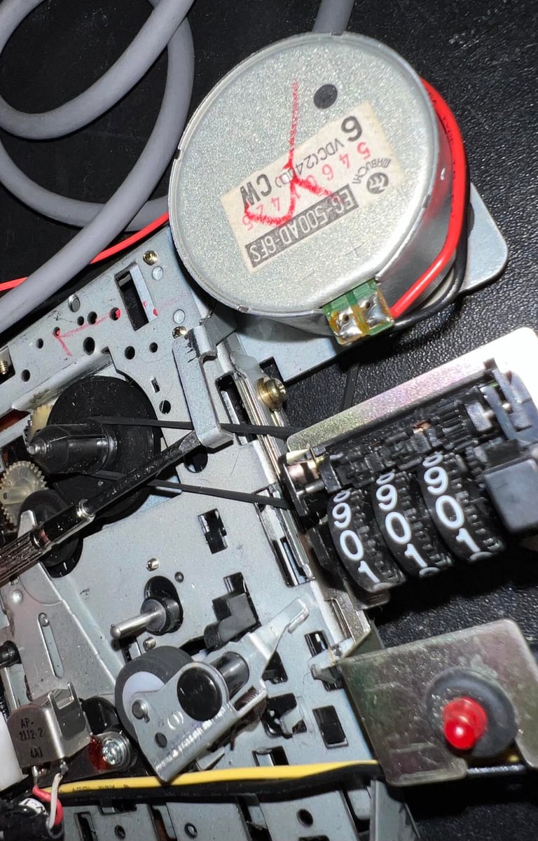
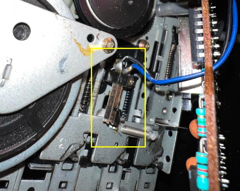
By using a small screwdriver I can adjust the speed of the motor easily. See picture below.

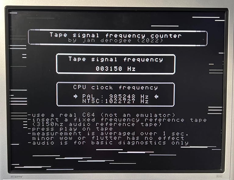
The screw is turned until "3150 Hz" is registered on the Commodore 64. The registered value fluctuates a bit - approximately from 3140 to 3160 Hz.
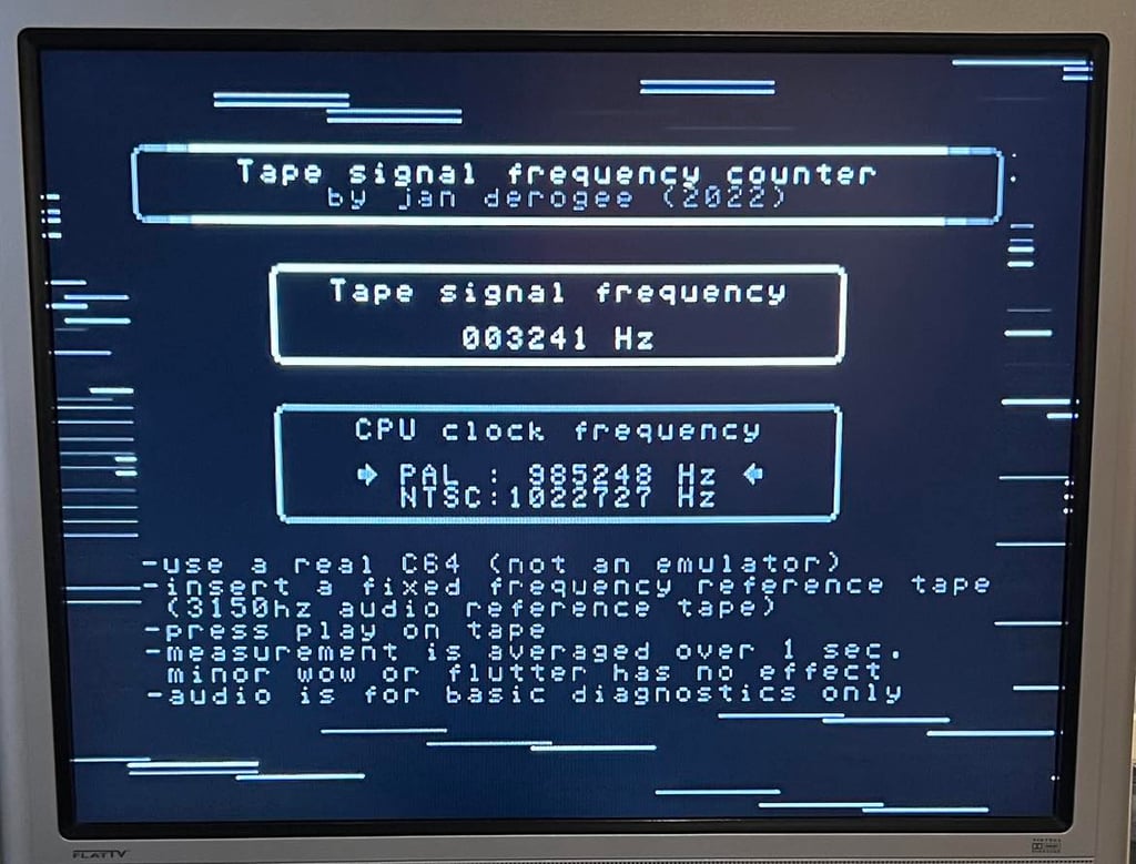
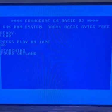
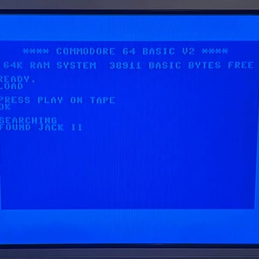
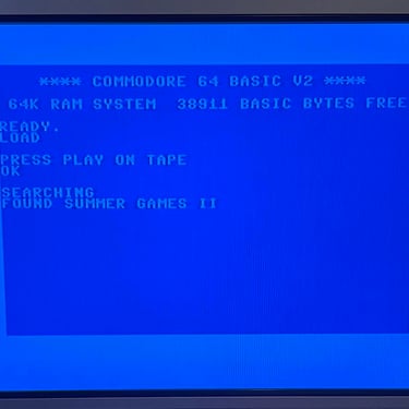
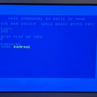
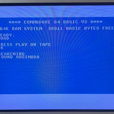
With the speed set to 3150 Hz I test the loading of a few games. And... well... only partly success. Some games load ok, but other fails after "FOUND <FILENAME>" is displayed. After some more adjustments and testing I find that a registered speed of 3240 Hz works fine! I am not really sure why, but at this playback speed all the games load without any issues.
I am a newbie with this tool so it could be that I didn´t to this correct. Anyway, I am looking forward to use this tool refurbishing datasettes in the future. And it is obviously that the playback speed can have significant impact on how successful loading games are. Below is a picture of the registered tape signal frequency when all the games loads without errors.
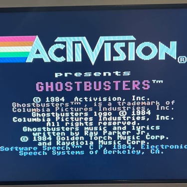
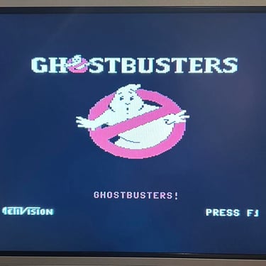
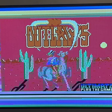
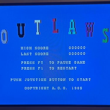
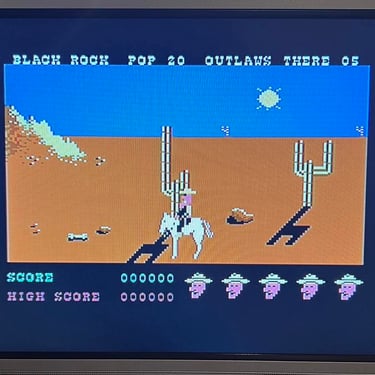
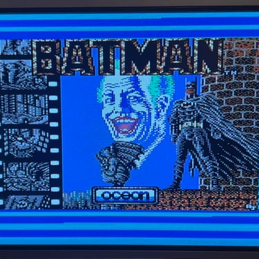
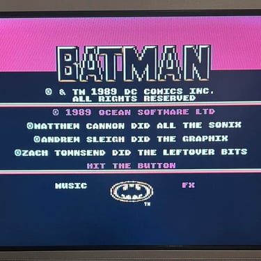
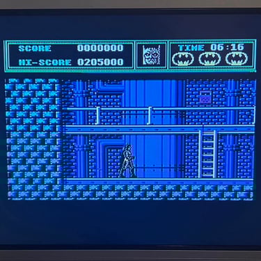
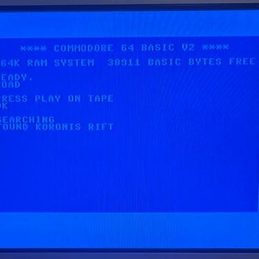
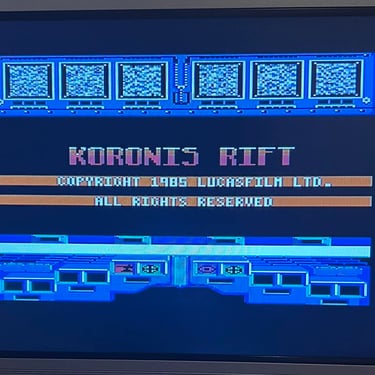
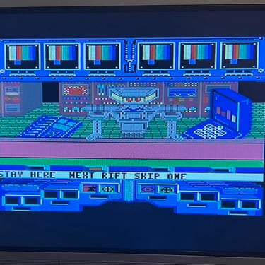
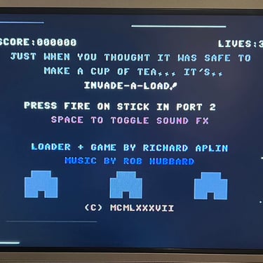
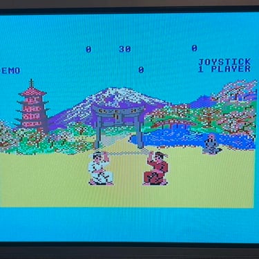
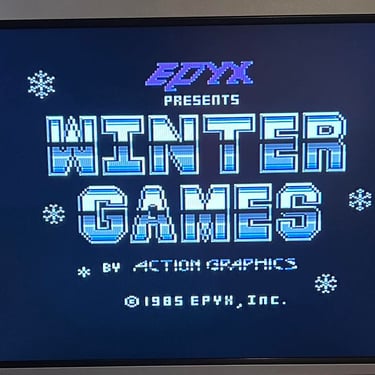
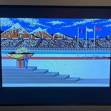
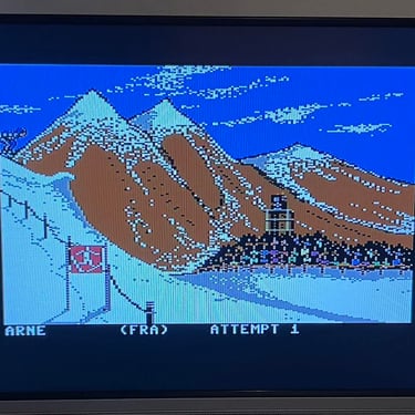
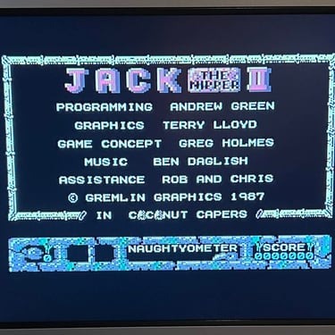
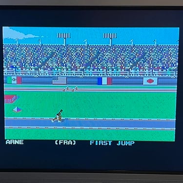
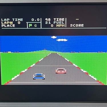
Playback
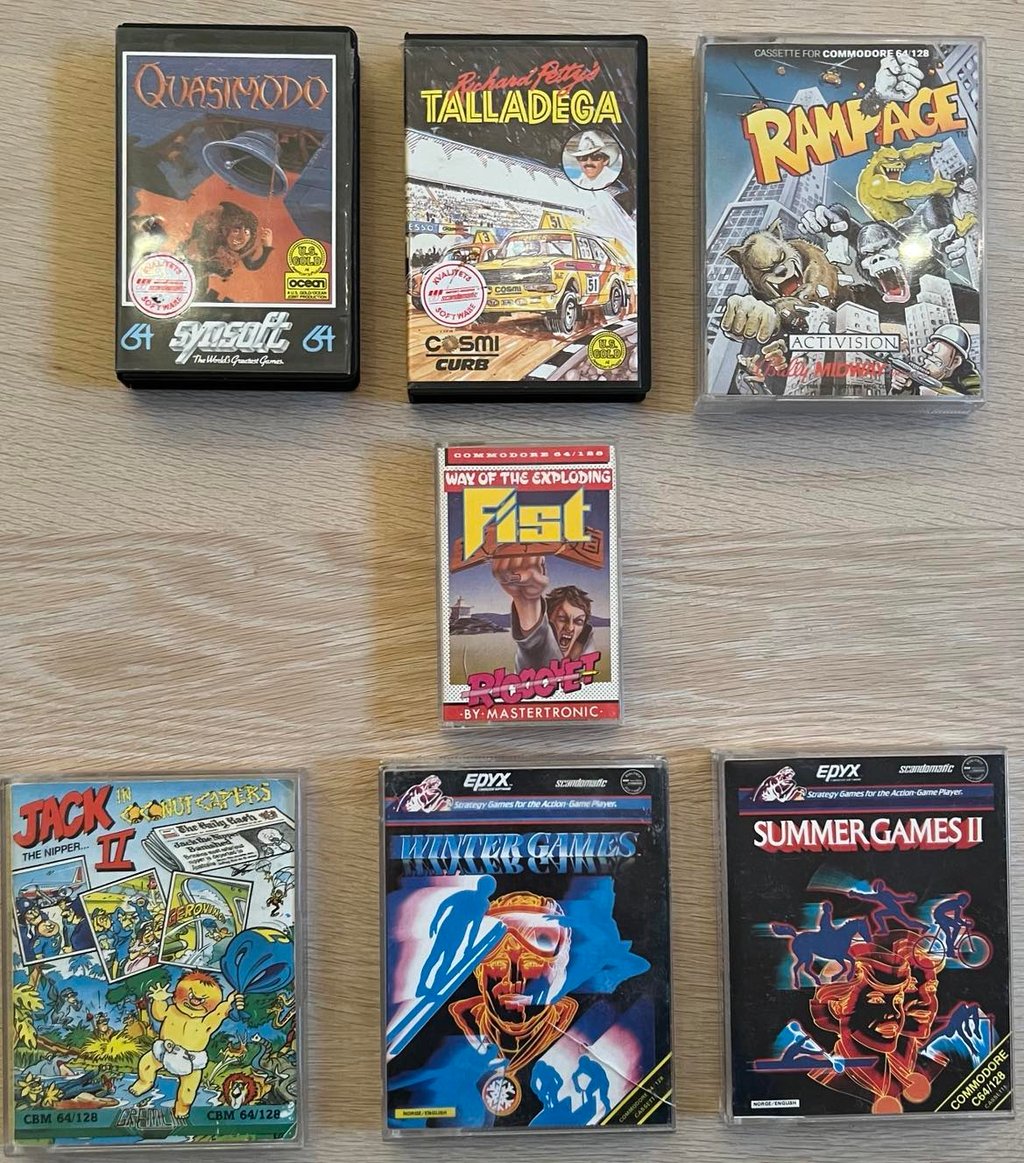
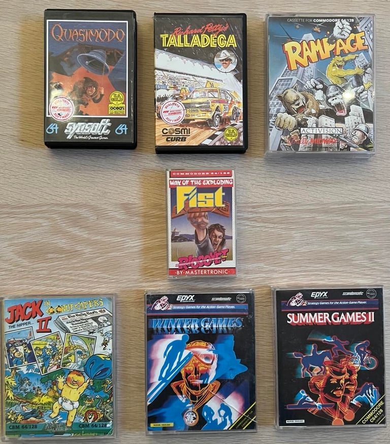
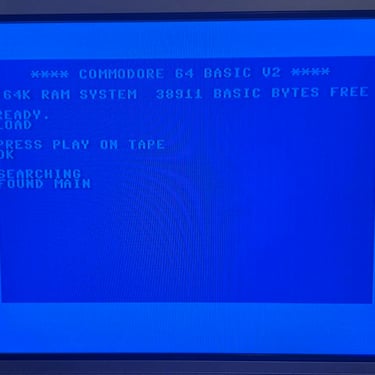
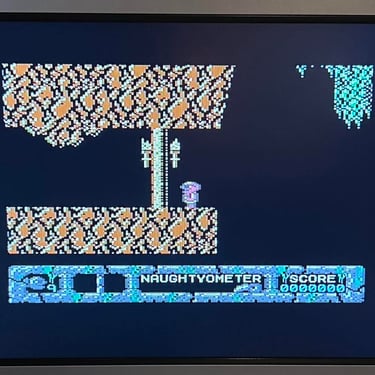
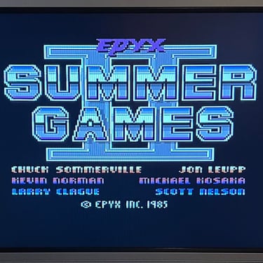
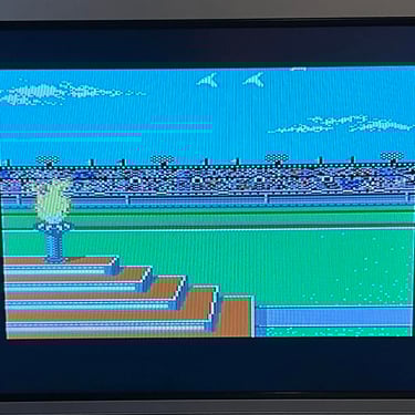
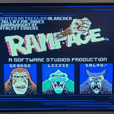
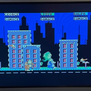
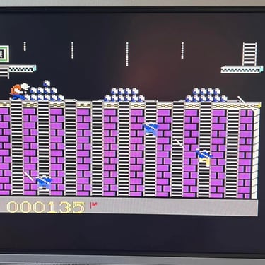
To make sure now works as it should I select seven (actually some more) original C64 games to be used for testing. Even if these games are old and worn the load without any problems at all. Below is a picture gallery from the testing.
Testing


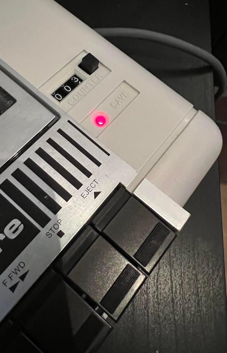
Recording
The saving functionality is also checked and verified. A small BASIC program is made and the SAVE command is used (and then the program is re-loaded). The LED is also on while recording is in progress.
Final result
A picture worth a thousand words"
Below is a collection of the final result from the refurbishment of this datasette. Hope you like it! Click to enlarge!


Banner picture credits: Evan-Amos