

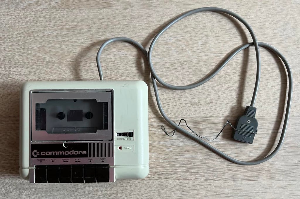
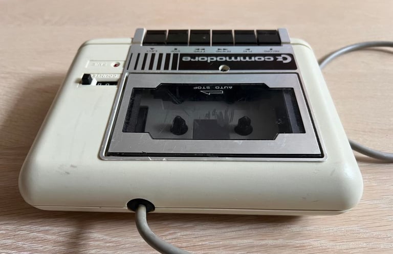
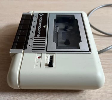
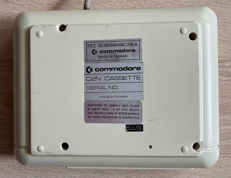
1530 (C2N)
Ser. No. 3437465
Starting point
My immediate reaction when I saw this datasette was "someone has tampered with this device". It does not look bad from exterior point of view except from some dirt and and marks, but the hole for the R/W align screw has been widened. I guess that a previous owner has only had a larger screw driver available and had to drill the hole a bit wider. Also, the tape lid opens up - but does not stay open unless the "EJECT" key is pressed. So someone has obviously tried to adjust or repair this device at some point in time...
Anyhow, I look forward to refurbish (and probably repair) this datasette!

Refurbishment plan
To refurbish this 1530 datasette the plan is to:
- Clean and remove stains from exterior casing
- Clean the interior mechanics
- Check cable and replace strain relief
- Check PCB for corrosion and replace old electrolytic capacitors
- Replace motor- and counter belts
- Check, and if necessary, adjust R/W head for optimal tape reading
- Check, and if necessary, adjust motor speed for optimal tape reading
- Verify datasette operation by testing
Note that these steps are not necessarily done in the order described above, and several of these steps are done in parallell.
Opening it up...
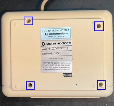
To open the datasette the four screws in the bottom cover are removed (blue squares).

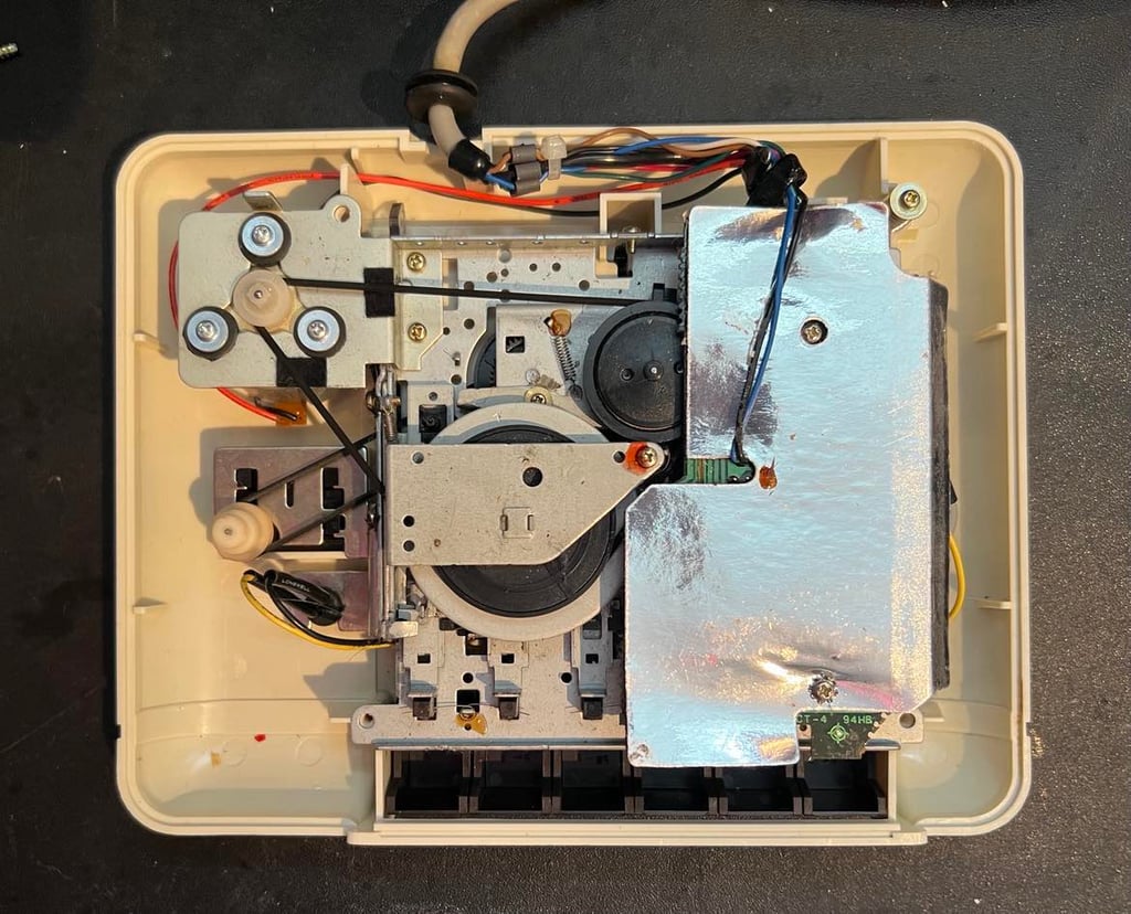
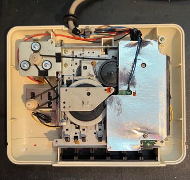
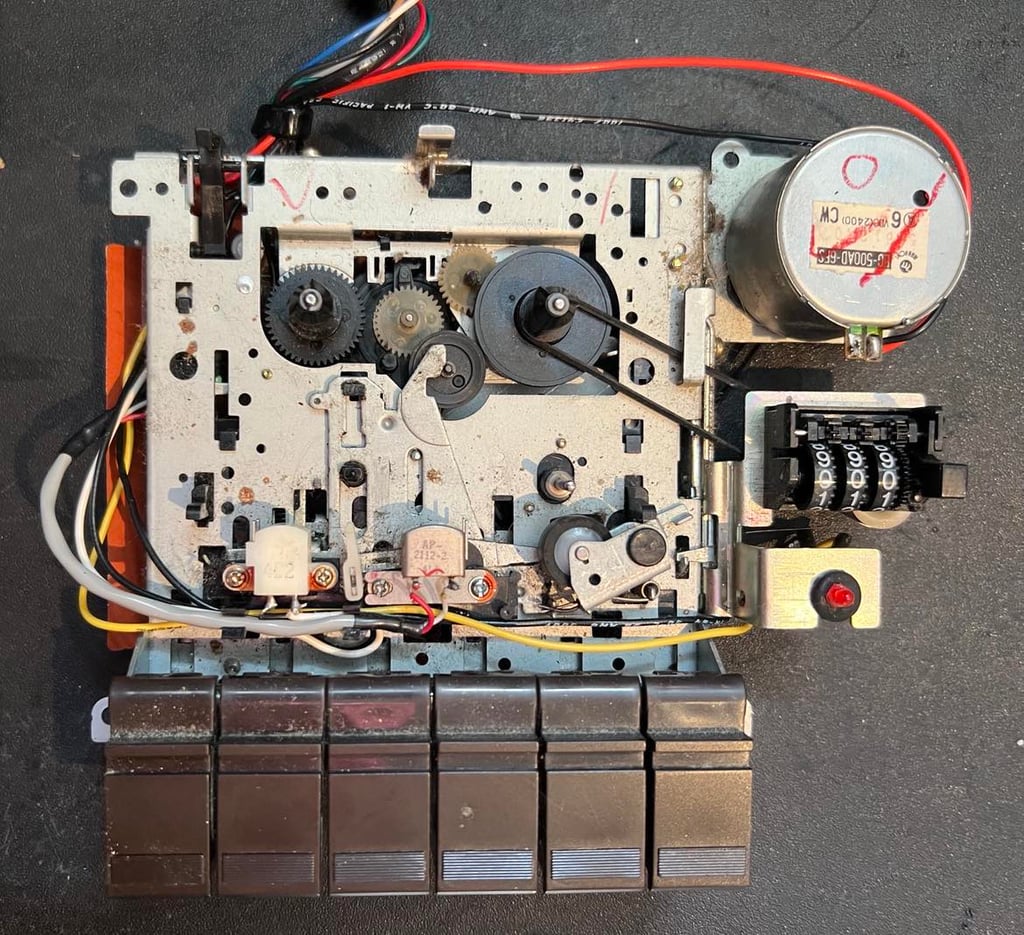
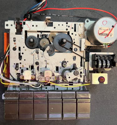
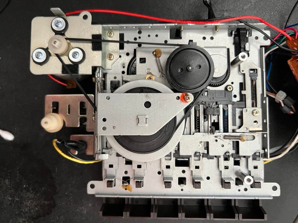
The bottom cover is lifted way and the interior is revealed. First impression is good; the interior is incredible dirty, but the belts looks to be in very good condition. I need to investigate this further, but the belts feels as "flexible" as they should. Have they been replaced by previous owner?
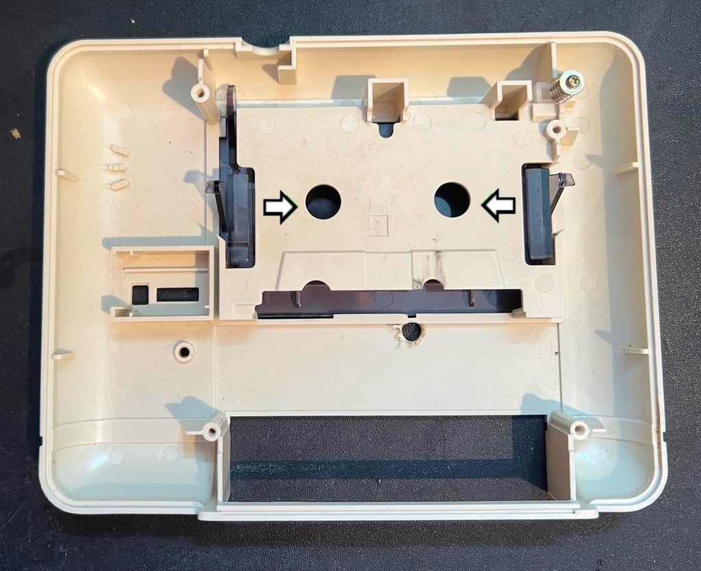
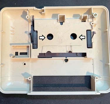
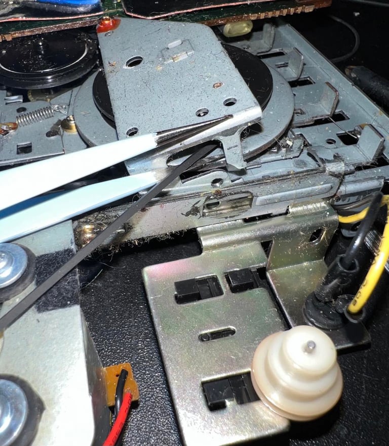
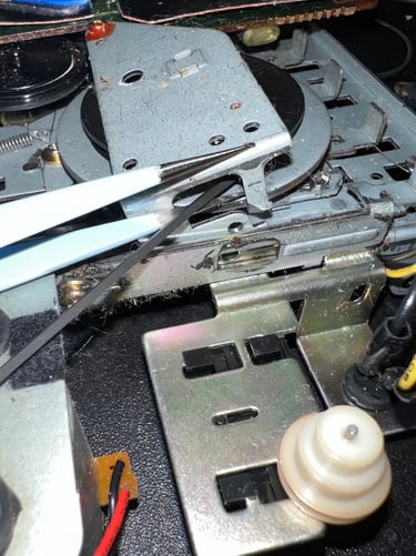
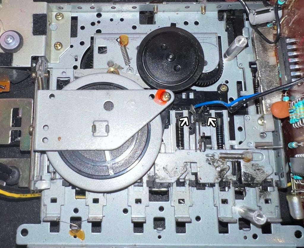
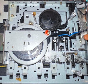
Next step is to lift the interior out of the top cover. There are no screws to be removed, but the interior needs some "wiggling" to get it out of the top cover. When the interior is removed the top cover is exposed completely. And now it becomes clear why the tape lid does not stay open - part of the plastic on the lid is broken and missing. The tape lid is lifted out of the top cover by pushing the two plastic arms towards the center (white arrows). And now it is very clear that the azimuth align hole has been widened. You can see the traces from the drilling.
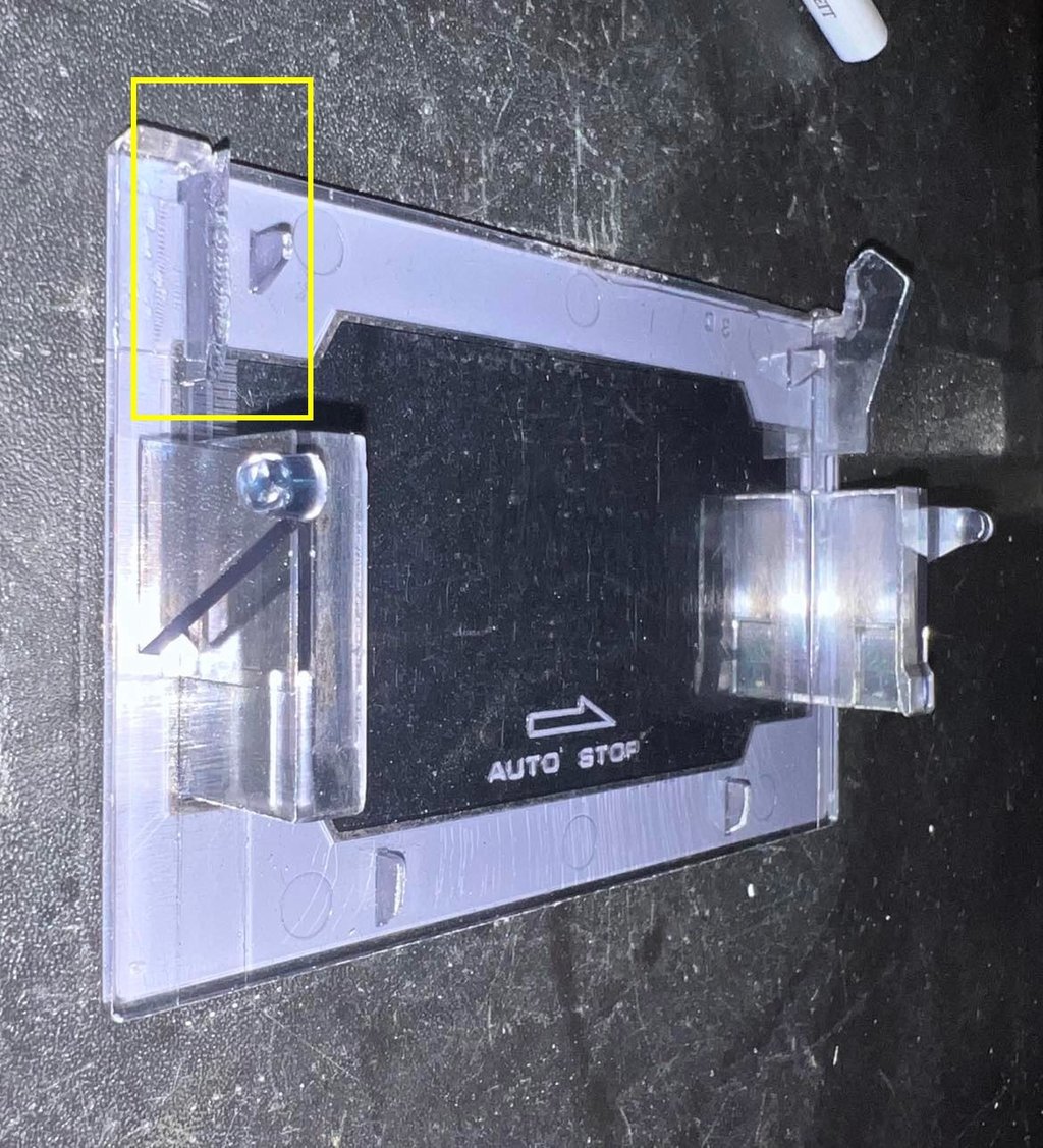
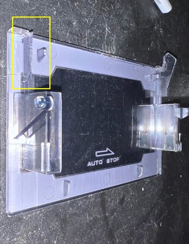
A close up of the tape lid show the missing plastic part (yellow square). I don´t think this is possible to repair unfortunately. I do not have the missing part, and even if I had 3D printed a part I don´t think that gluing it back would hold.
Holy moly this datasette interior is dirty. There is grease, dust and dirt all over the place. But with some properly cleaning with isopropanol it should be ok...
Removing the keys
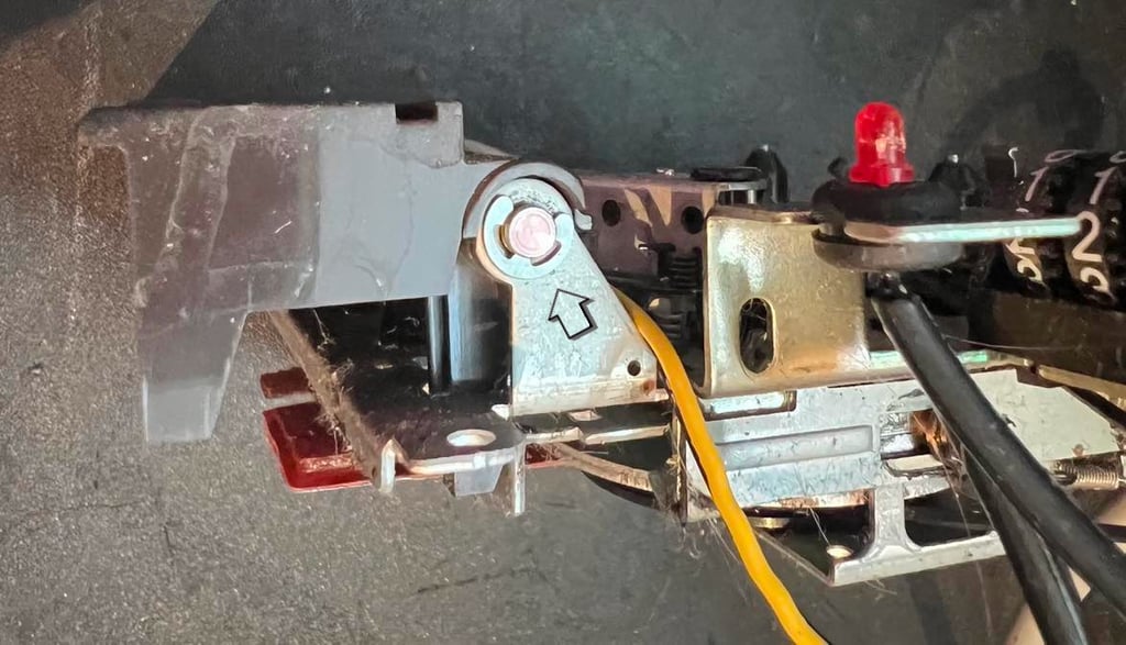
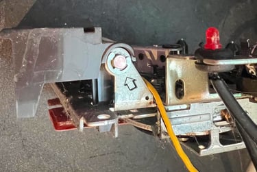
Before cleaning the interior the six keys are removed. This is done by first removing the E-clip (see arrow below) with a small flat screw driver.
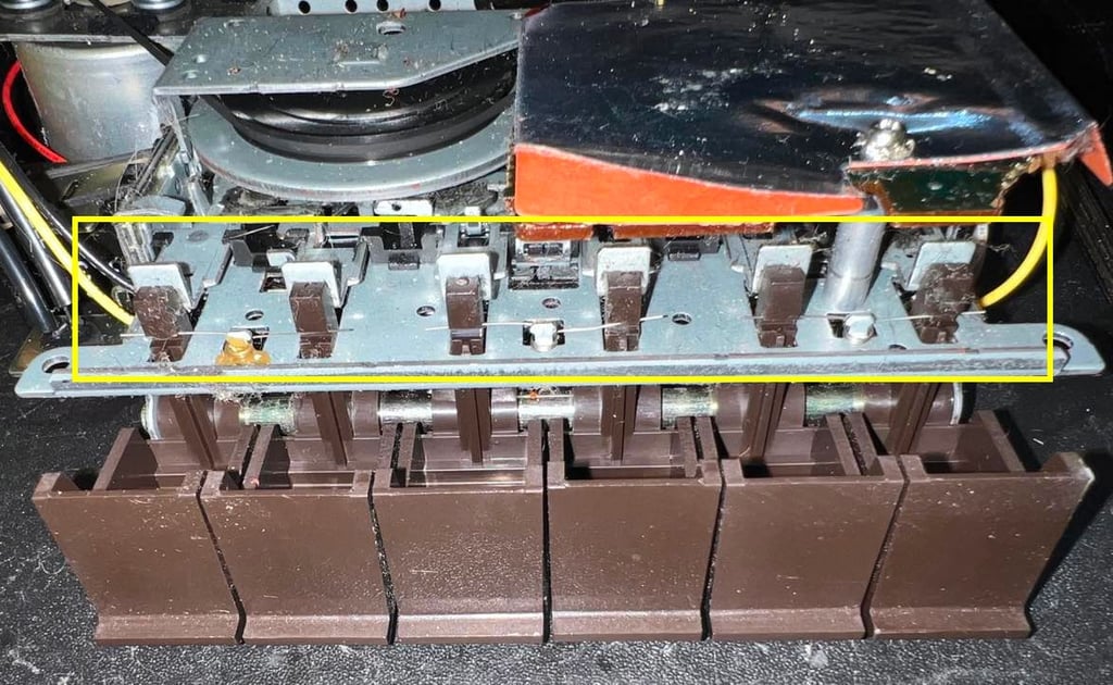
The interior is flipped upside down and the three springs are removed from the small notches in the keys (note that these springs have a tendency to fly all over the place so make sure to secure them in a small bag). See yellow square below for the position of these three springs.
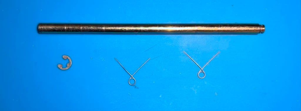
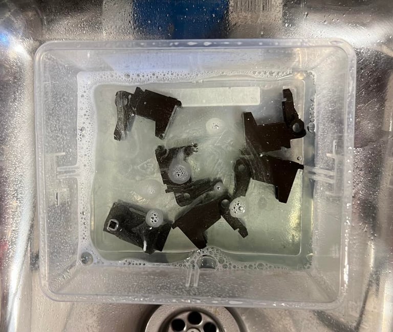
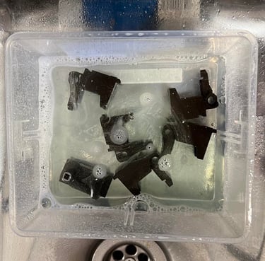
Finally the shaft is pulled out from the keys. Note that one of the three springs are fastened with some glue, but the other two are removed. The keys are placed in mild soap water combined with some glass cleaning spray for a few hours.
Removing the belts
In addition to removing the keys before cleaning the interior the counter- and motor belts are also removed. The counter belt is easy to remove. As seen from the picture below the small arm is lifted, and the counter belt is removed.
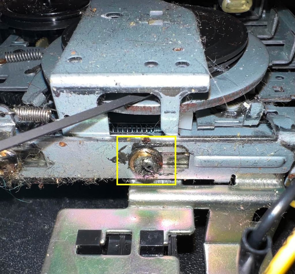
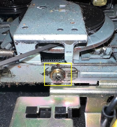
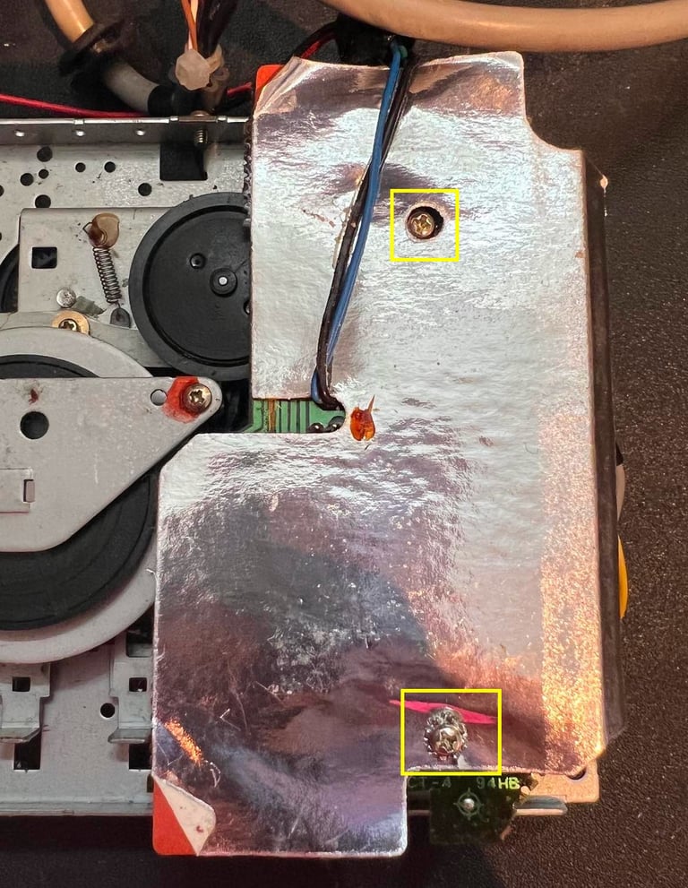
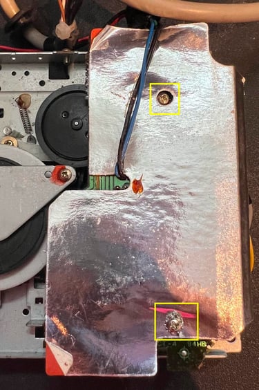
The motor belt is also easy to remove - if you "do it right". If you remove too many screws and springs it is quite a challenge to assemble the whole thing again. First the screw and spacer on the side is completely removed (see yellow square).
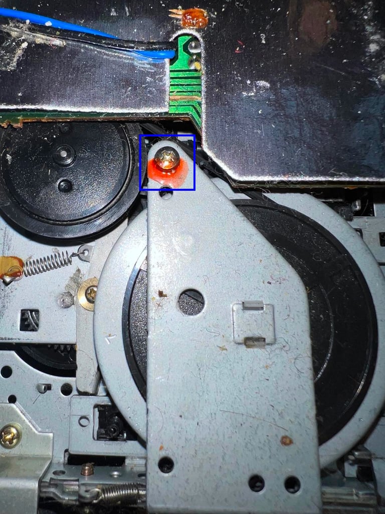
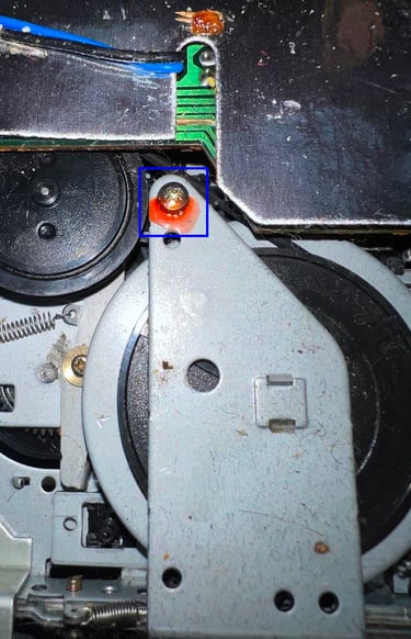
Next the top screw on on the metal bracket holding the flywheel is only partly removed. It is enough to unscrew this only halfway - just so that the metal bracket can be lifted slightly. In the pictures below the position of the top screw is shown (blue square) and the metal bracket slightly lifted.
Removing the PCB
Although not strictly required it is good practice to partly remove the PCB also before cleaning the interior. This is done by removing the two screws (yellow squares in picture below). Note that the bottom screw holds both the RF-shield cardboard and PCB, and the top screw only holds the PCB.
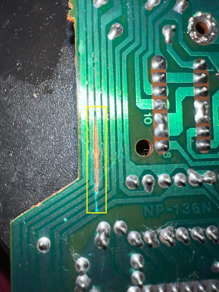
With the RF-shield removed the PCB is revealed. It is full of flux residue and sticky grease. I can see some kind of rift (?) left to the two wires, but I am not sure if this is any real damage, but oh my this is sticky...
The PCB is tilted so that he leaf switch below is exposed. The two wires connected to the leaf switch are desoldered (see arrows below for the positions).
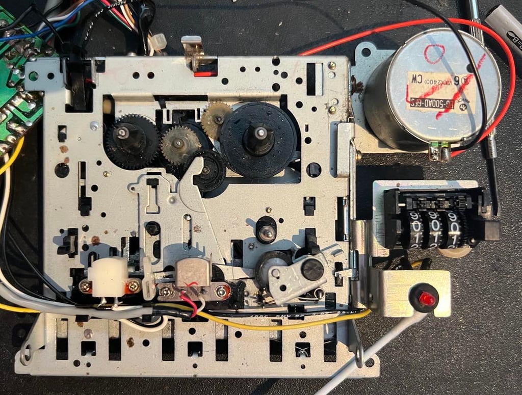
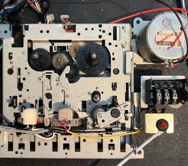
Interior
The interior mechanics are cleaned properly with isopropanol. This interior was incredibly dirty, but it looks very nice after the cleanup. I can not see any damage to the interior. But I am absolutely confident that some previous owner has tried to adjust (or repair) this device.
PCB and electrolytic capacitors
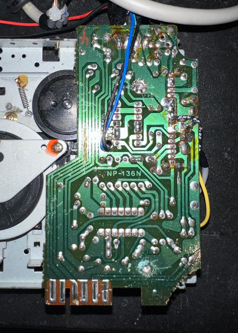
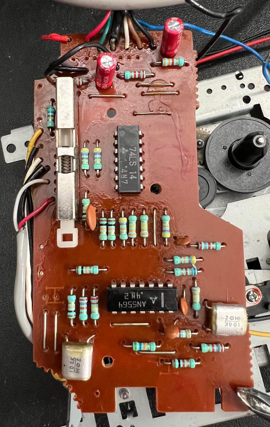
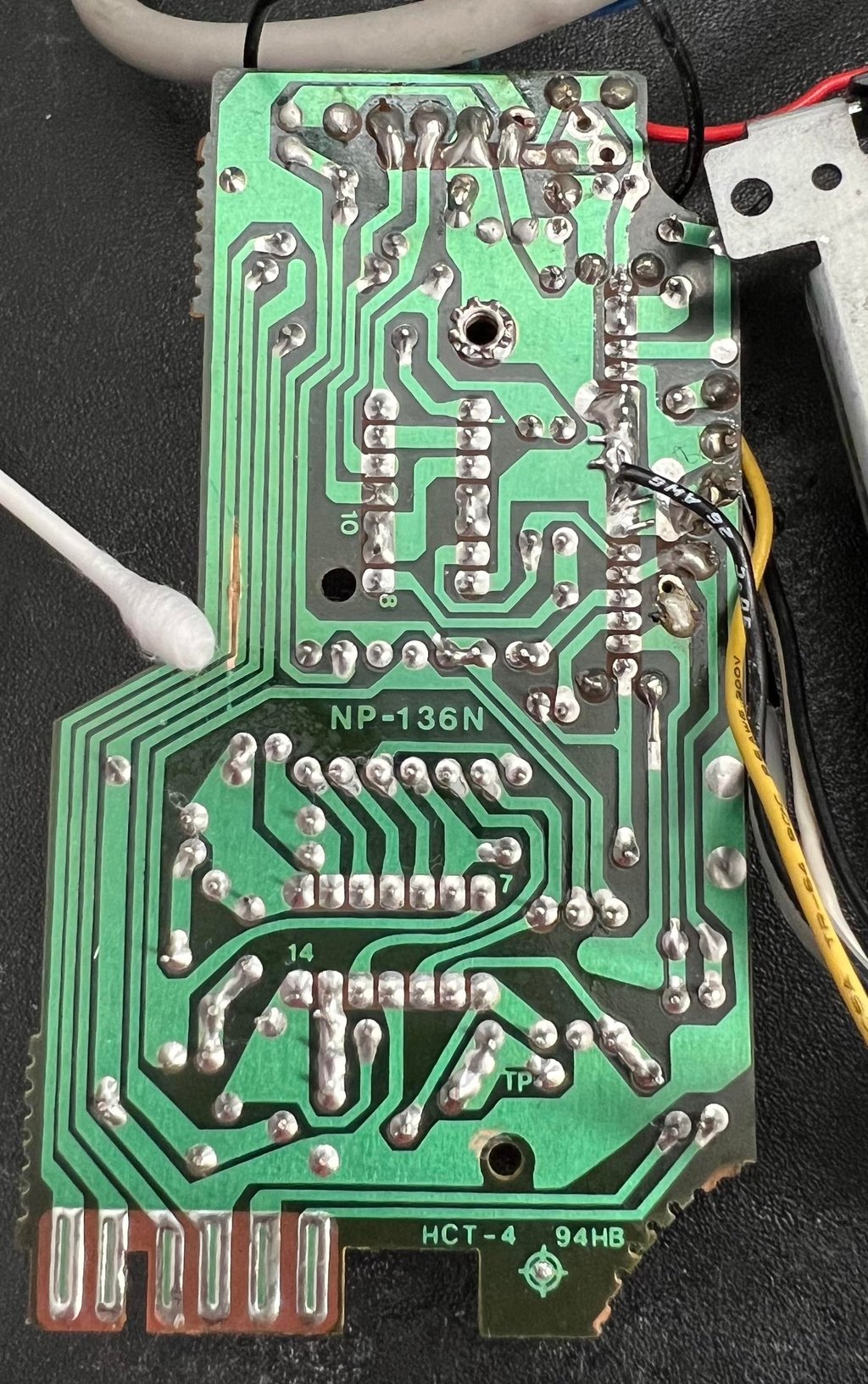
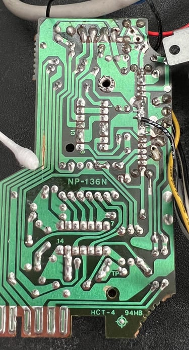
This is a NP-136N PCB where all the four OPAmp´s are within one IC AN6564 from Matsushita. As previously mentioned the PCB is full of sticky residue so this will be cleaned. But during close inspection I find some interesting findings:
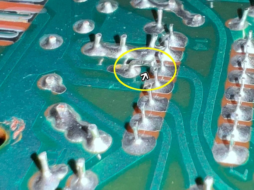
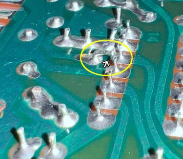
On the backside of the PCB of the pins are not cut properly. So there is a very small gap between two pins - could almost be a short circuit. So this pin will be cut down properly.
One of the wires from the read/write (R/W) head is not connected? It is probably broken from the PCB and needs to be repaired.
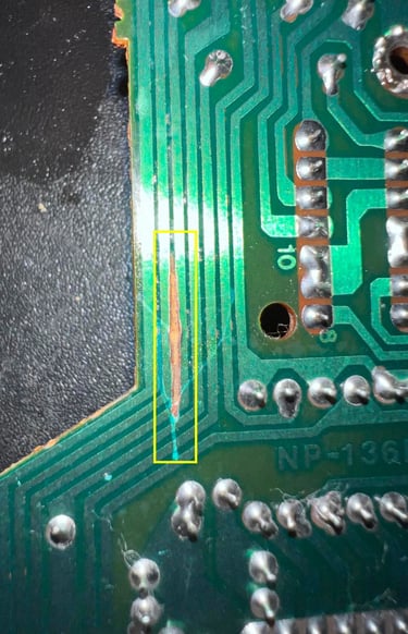
The is a rift close to the copper trace. It does not look to be more than a rift in the isolating material so should not be any problem, but I will check eventually.
See pictures below.
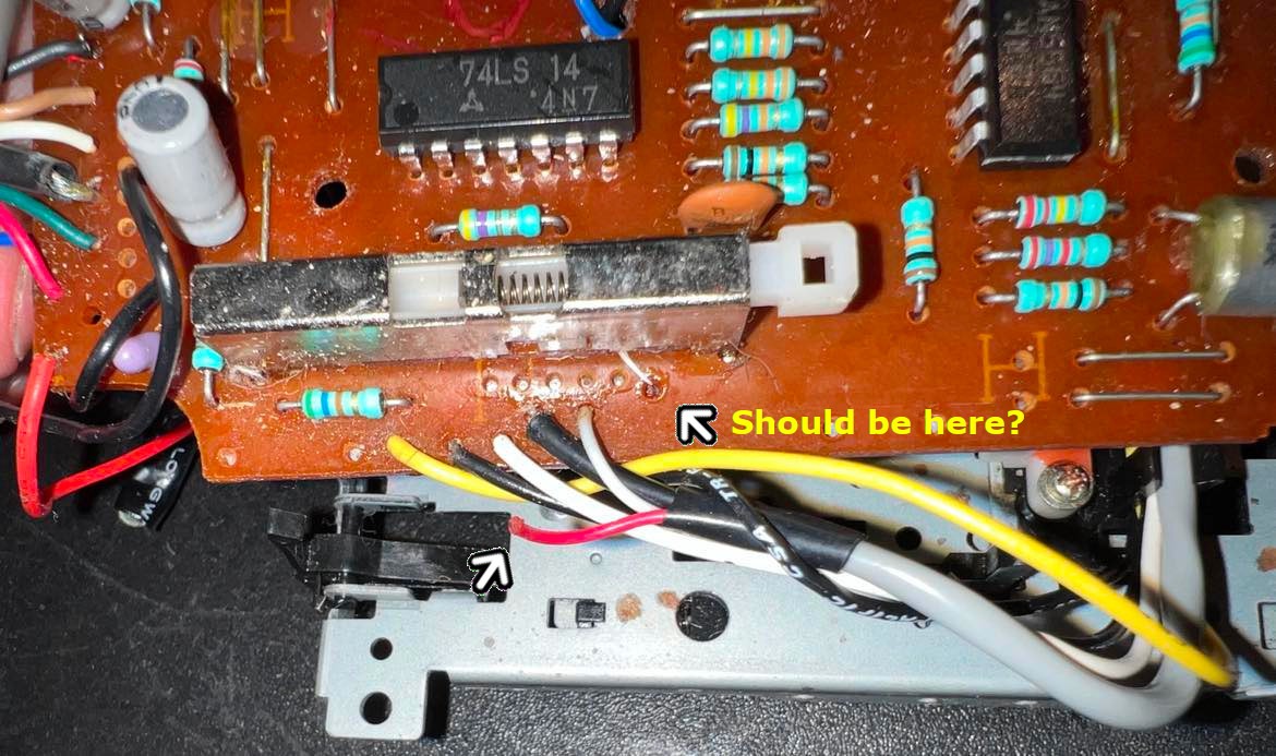
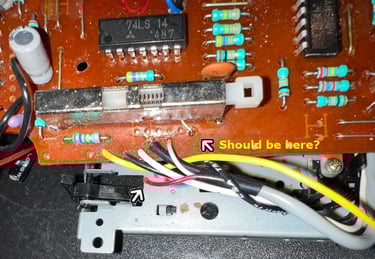
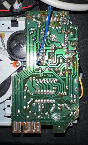
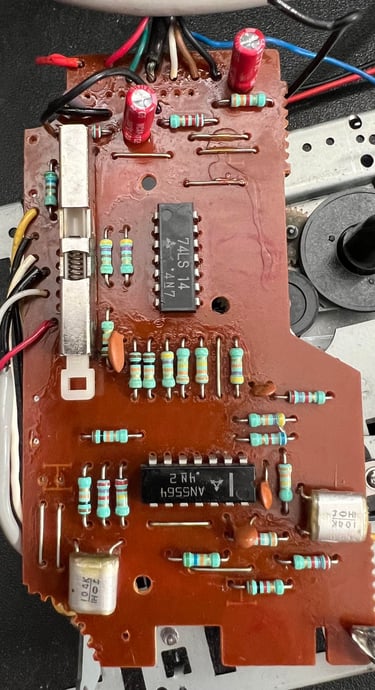
Both the front and back of the PCB is properly cleaned with isopropanol. There are two 47 uF [10 V] electrolytic capacitors which are replaced with new capacitors from Wurth Electronics. Also, the broken (?) wire is soldered back to the PCB where I assume it was connected previously. See pictures below of the cleaned PCB and with new capacitors and connected R/W wire.
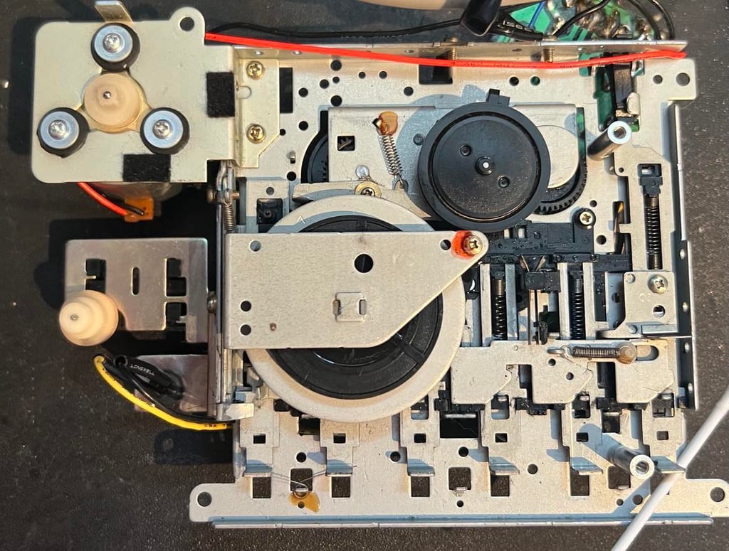
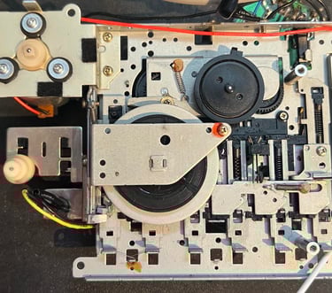
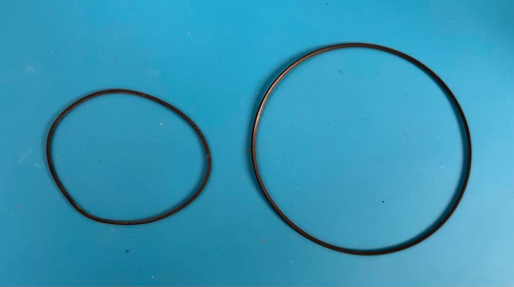
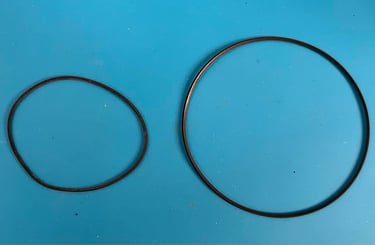
Counter- and motor belt
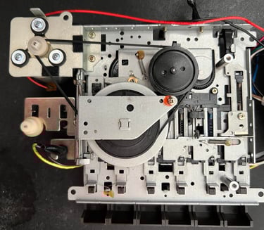
The counter- and motor belts in this datasette are surprisingly elastic and minimal deforming. It is like I almost think they have been replaced not too long ago. So I will start using these belts, and only replace if required. See pictures below.
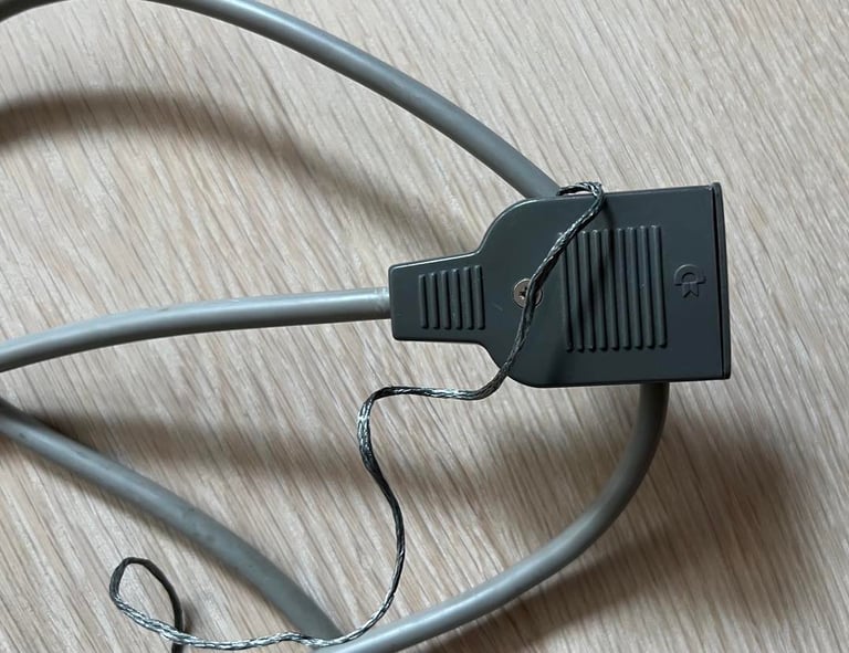
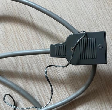
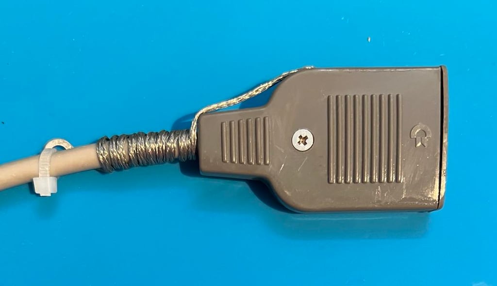
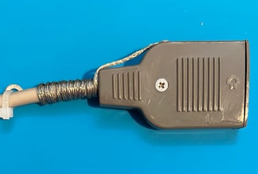
Cable
Both the connector and the cable itself looks to be in very good condition. The connector is disassembled and the parts are cleaned with isopropanol.
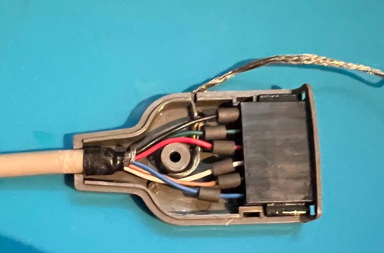
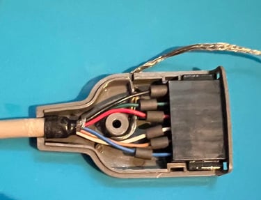
It is common for 1530 C2N datasettes to have a ground wire - which is not used. This ground wire is legacy from the PET area (and from old FCC regulations in the US). Nevertheless, the ground wire represents a danger. If by accident the wire enters the user port it can short circuit the Commodore 64. Therefore the ground wire is twisted around the cable and fastened with a cable tie. I find this better instead of cutting away the whole wire.
Testing
#SPOILER ALERT! - This datasette does not work... Repair is required!
Initial testing
When the datasette is connected and powered by the Commodore 64 the datasette motor starts as it should. And all mechanical functions such as PLAY/REW/FF/STOP etc. works as far as I can see.
But when a tape is attempted to load nothing is actually loaded to the Commodore 64 it seems. It is like the Commodore 64 is waiting to receive data from the datasette, but they are never sent from the datasette?
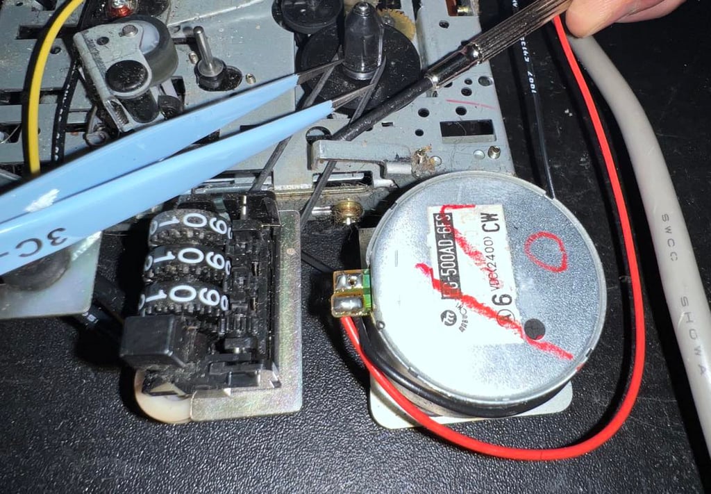
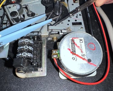
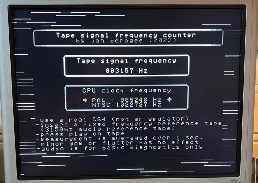
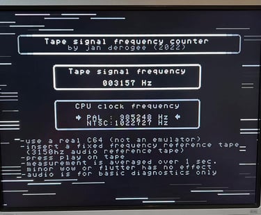
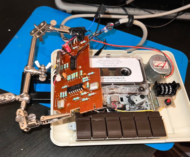
The Audio cassette speed calibration test tape is loaded and the Tape signal frequency program is loaded on the C64. The result is quite interesting; the C64 detects data from this tape and also the speed seems to be right! Could it be that the R/W head is misaligned? As can be seen from the picture below the tape frequency is actually measured to be 3157 Hz (from a 3150 Hz reference tape).
Repair
This datasette is obviously in need of repair. I have already fixed a broken wire from the R/W head, but as the testing in the previous chapter shows the datasette doesn´t load anything...
Checking the azimuth head alignment
The first natural thing to check is the read / write (R/W) head alignment. Since I already know that something is transferred from the datasette to the Commodore 64 it is possible that the head is just misaligned. How do I know that something is transferred? Well, I know that the Tape signal frequency counter is detecting a signal - and that this signal is correct. But, could be that the R/W is misaligned so that the input signal in the 4x OPAmp chain is not able to produce a correct digital signal?
To check the azimuth head alignment I use an oscilloscope and follow the method described in "HOWTO - Datasette head alignment".
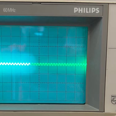
With a screwdriver I align the R/W head to output the maximum output. But, even if it is adjusted to give the maximum output if looks to me that the signal level is too low. See picture below.
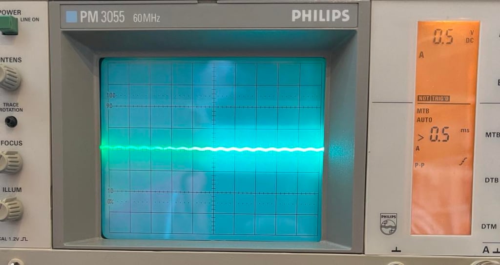
Checking the OP-Amp chain
The signal from the R/W head is amplified, and converted to a digital signal, trough a series of four OP-Amps in a chain (all four OP-Amps are in the AN6564 chip). See schematics below.
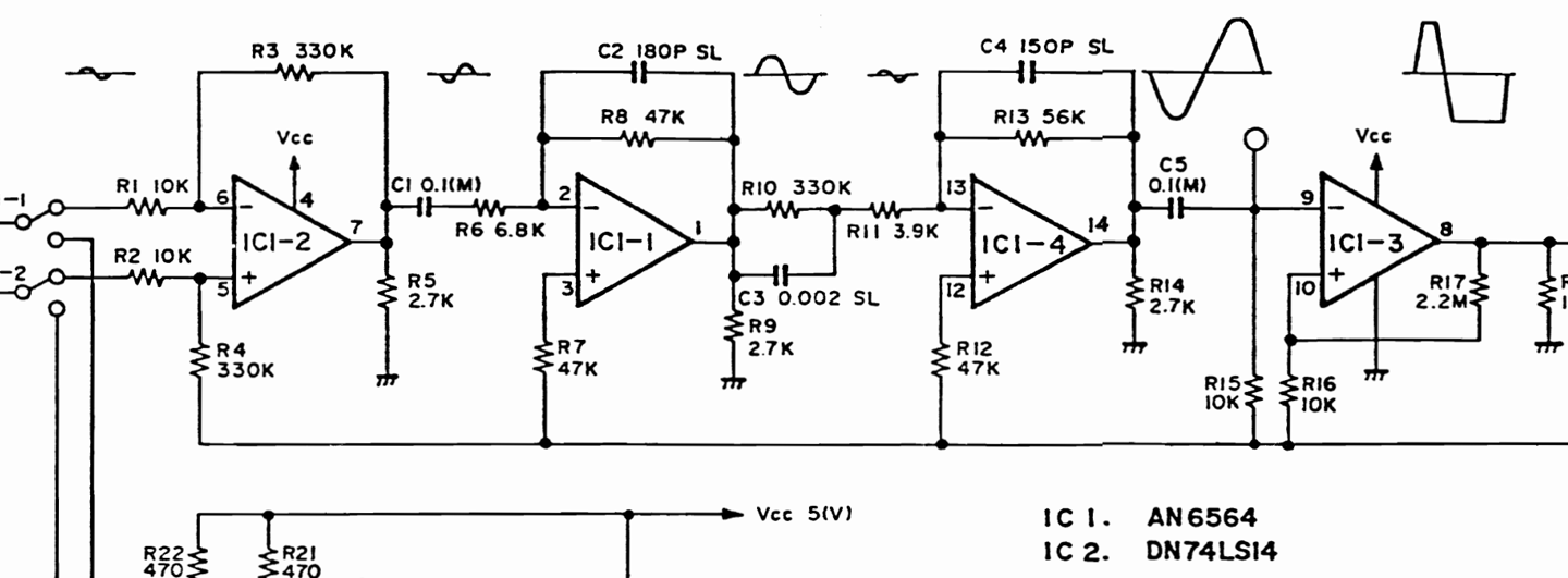
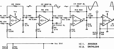
As can be seen from the schematics above the analog signal is continuously amplified until it is saturated. And when it is saturated it is for all practical purposes a digital signal. In the picture gallery the signal is measured at pin #7, #1, #14 and #8. Note that for the first three signals the scope settings are 0.2 V/DIV and 1 ms/DIV, while for the last one the settings are 0.5 V/DIV and 0.5 ms/DIV.
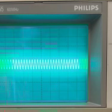
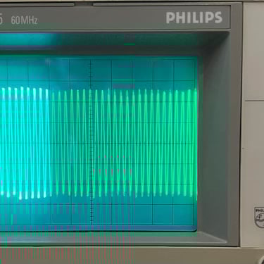
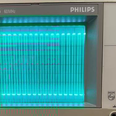
The amplifying chain is obviously working. The signal is increasing in amplitude for each stage ending up in a saturated signal (digital). But what I now see is that in output signal in the first stage (PIN #7) is identical to the input signal (PIN #6 and #5)? So it looks like there is no amplification (or that the amplification = 1) ? This does not look right to me. The level of amplification in a OP-Amp stage is defined by the the resistors/capacitors in the feedback loop. And from the schematics this does not look like a 1:1 amplification stage.
So my hypothesis is that either the first OP-Amp in the AN6564 is faulty or something is wrong with the resistor/capacitor network surround the first stage.
Checking the resistor network - Stage #1
A quick check with the multimeter shows:
170 kOhm between PIN #7 and PIN #6 (output <> neg. input)
170 kOhm between PIN #7 and PIN #5 (output <> pos. input)
2.7 kOhm between PIN #7 and ground (output <> ground)
According to the schematics there should be 330 kOhm resistors in use between output/input, but I think that what I measure are these two in parallall (330 kOhms / 2 = 165 kOhms).
So I can´t see any immediate problems here.
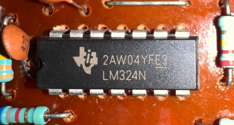
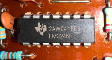
Replacing the AN6565 OP-Amp
After some more measurements with oscilloscope I don´t really think the OP-Amp is faulty. Nevertheless, I decide to replace the AN6564 OP-Amp with a Texas Instruments LM324 which is a modern equivalent. The result after this replacement is unchanged; still not able to load a game successfully. When a file is found only garbled characters are shown and loading doesn´t work.

A shot in the dark - replacing the 74LS14
There is a second chip on the PCB - a 74LS14 (a hex schmitt - trigger inverter). Measurements I have done with the oscillocsope show no sign of anything wrong here, but I choose to replace it anyway with a new modern replacement.

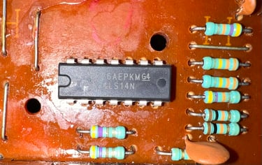
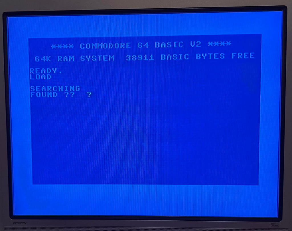
The result is still the same. When a file is found it is just garbled characters on the screen. See picture below.
Banner picture credits: Evan-Amos