

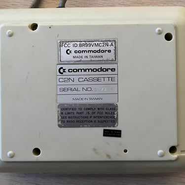
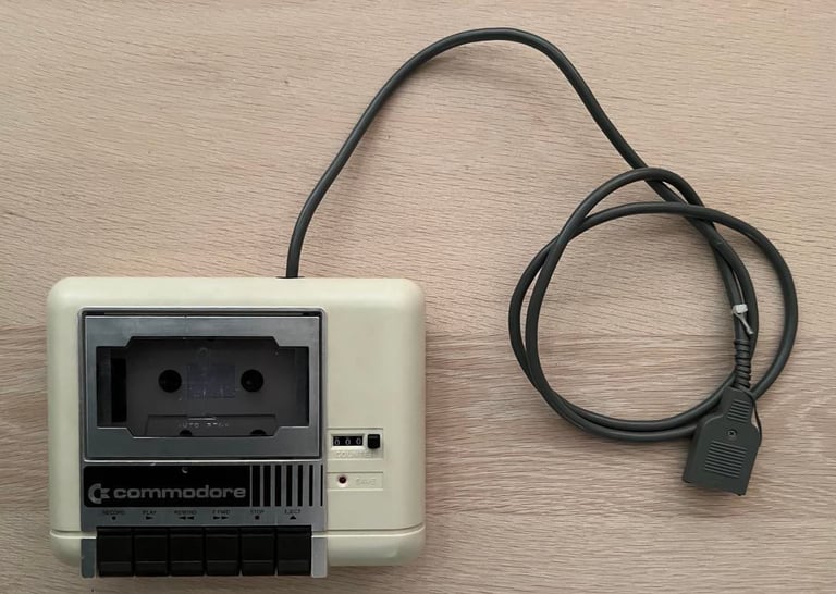
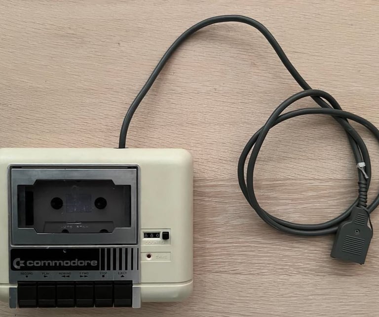
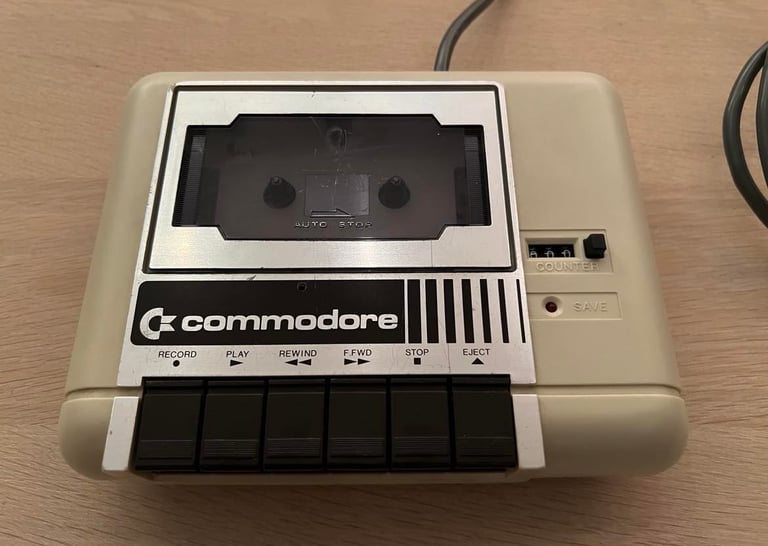
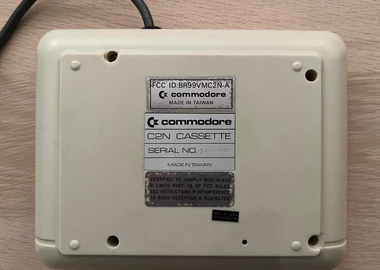
1530 (C2N)
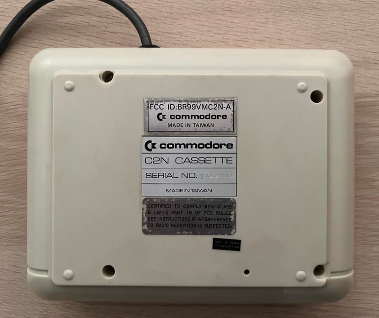
Ser. No. 3444224
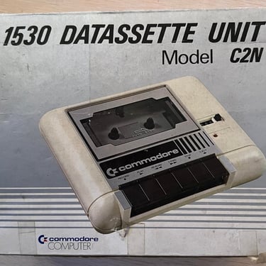
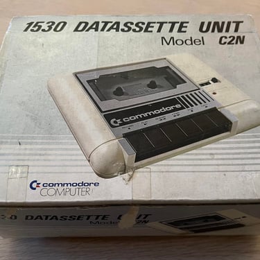
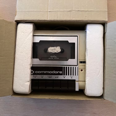
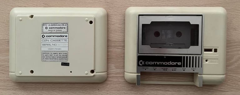
Starting point
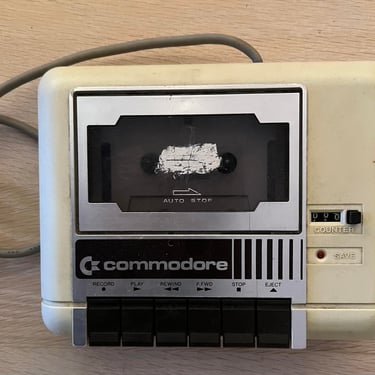
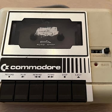
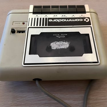
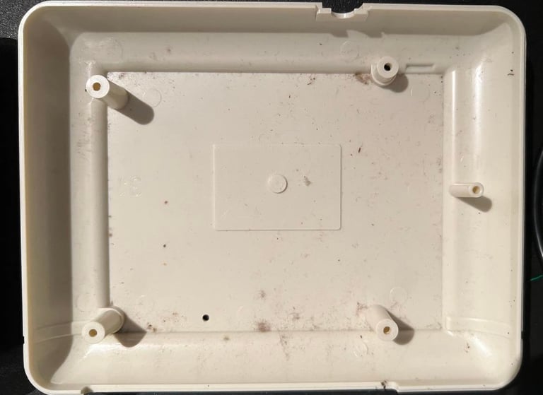
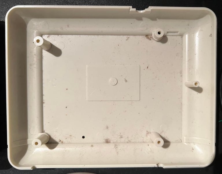
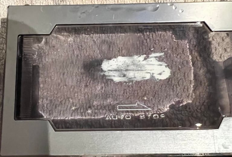
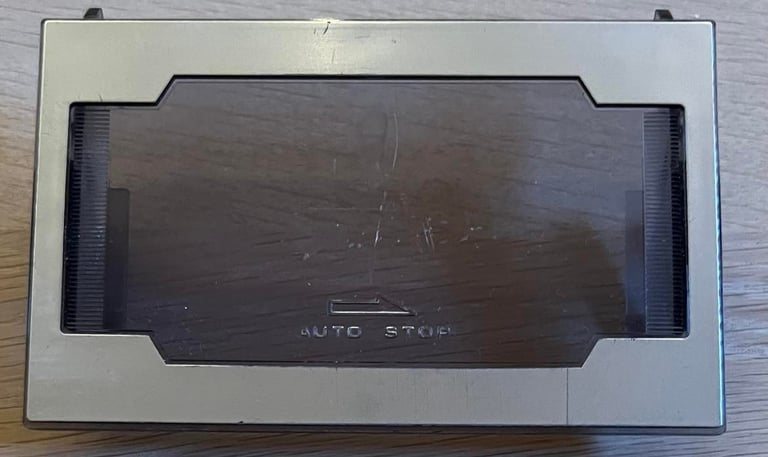
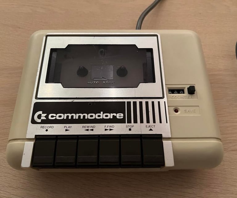
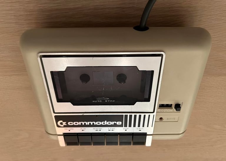
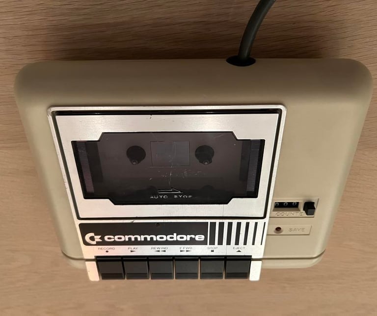
On the positive side this datasette looks to be undamaged, not too yellowed and in general good condition. But on the negative side there are several mark, stains and scuffs - and especially some mark on the tape lid. I believe I will be able to fix the datasette to be in working condition, but if I will succeed in removing all the marks? I really don´t know... Time will show.
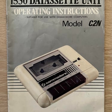
Also, the datasette is stored in the original box and user manual is in the box. Nice! Doesn´t look too bad after all these years.
Pictures below shows the state of the datasette before I start the refurbishment.
Refurbishment plan
To refurbish this 1530 datasette the plan is to do this trough the following steps:
- Clean and remove stains from chassis
- Clean the interior mechanics
- Check cable and replace strain relief
- Replace motor- and counter belts
- Check PCB for corrosion and replace old electrolytic capacitors
- Adjust head for optimal tape reading
- Verify datasette operation by testing
Note that several of these steps are done in parallell.
Exterior chassis
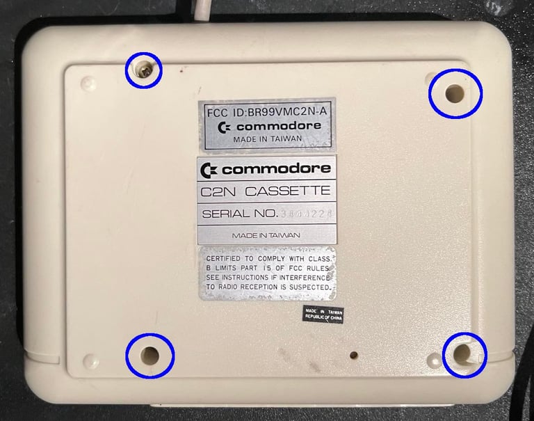
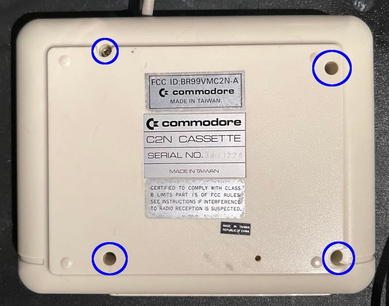
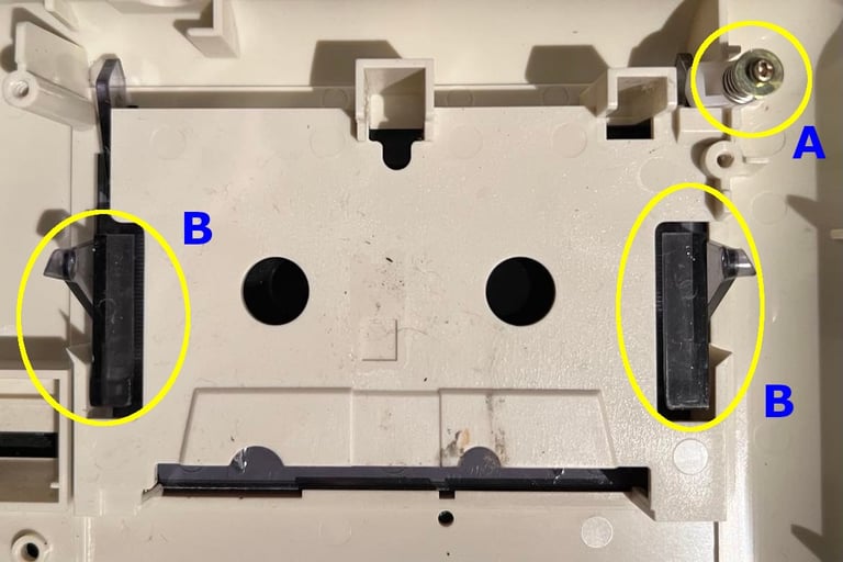
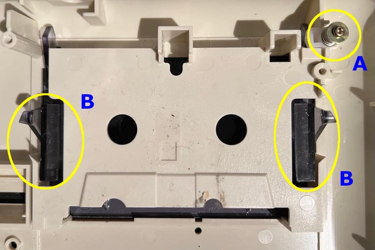
Before cleaning the datasette is disassembled. This is done by removing the four screws at the bottom of the datasette - see circled areas in picture below.
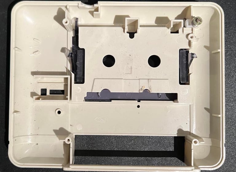
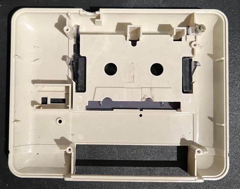
The two parts looks to be undamaged, but they are full of dust and grease.
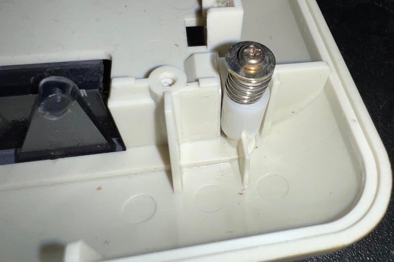
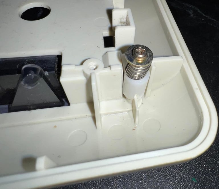
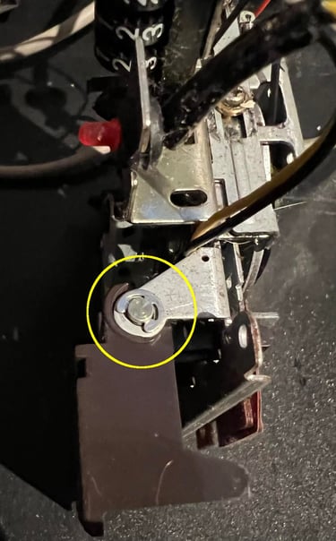
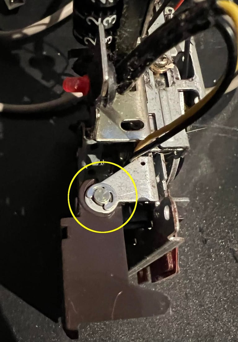
Next step is to remove the tape lid. This is done by first removing the screw marked in position "A". Note that this screw holds a spacer, a spring and a small plastic plunger. When the screw is removed the two plastic "arms" (marked in position "B") towards the center. This will loosen til tape lid from the tape cover.
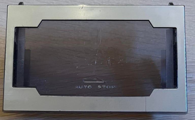
As seen from the pictures from the "Starting point" chapter there is some white paint(?) on the tape lid. I remove this with some isopropanol, a cleaning cloth and isopropanol. This is not an easy task. I used about an hour to remove it - but I think the result was worth it.

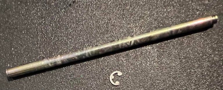
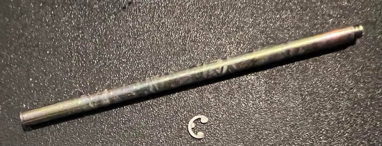
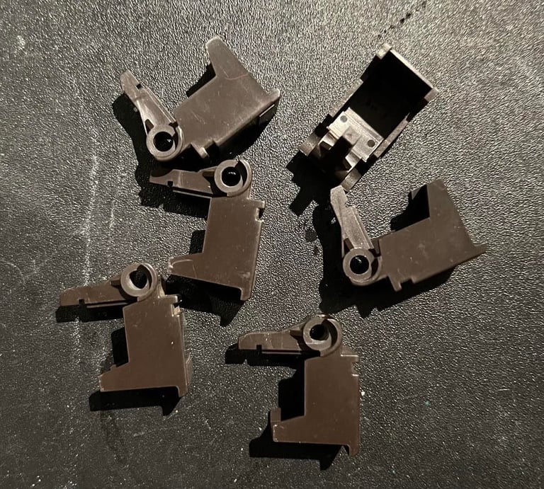
The six keys are also disassembled for cleaning. To do this I first remove the small clip on the right side of the datasette (see picture below). Then the shaft which holds all the keys are gently pushed to the left side.

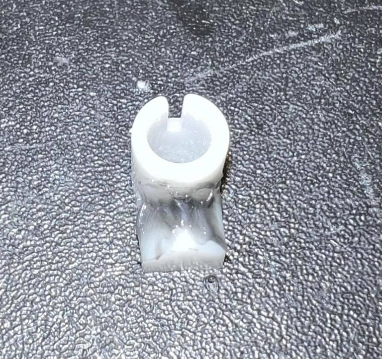
A small useful tip is to use some small amount of grease on the little plastic bracket which is used with the tape lid. This will make the lid open / close a bit more gently.
The top- and bottom cover are cleaned with some glass cleaning spray, isopropanol and a cloth with soap water. I think the result is very good.

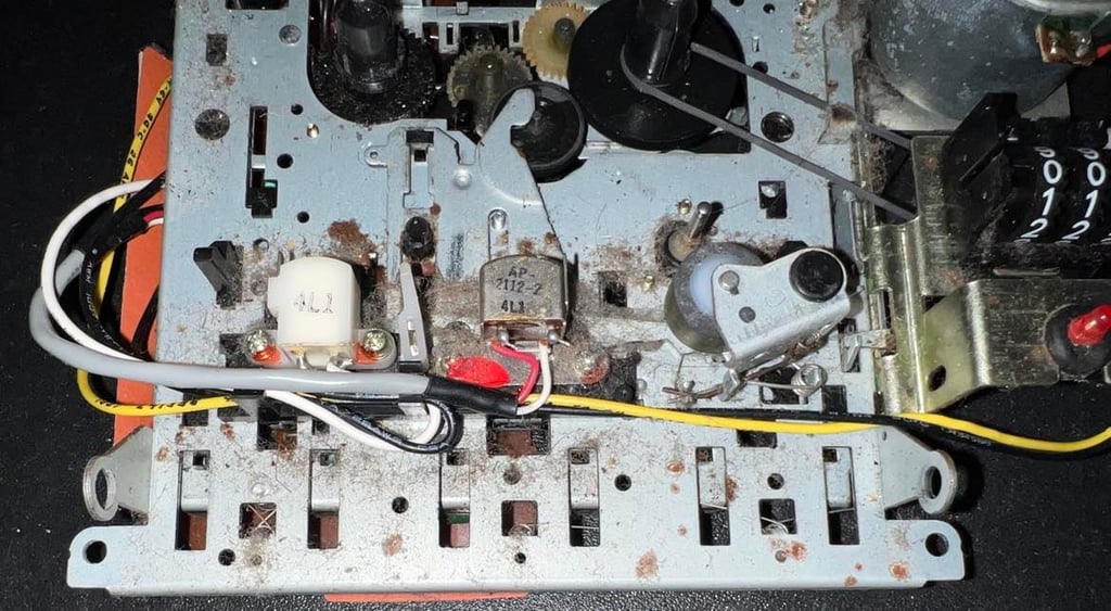
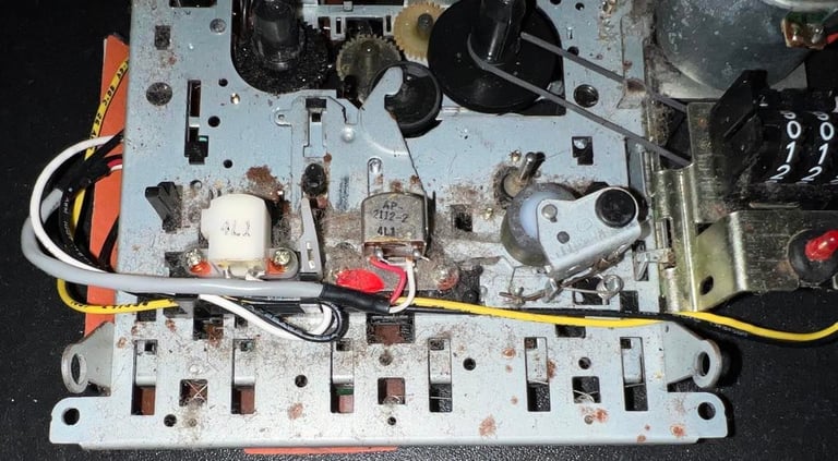
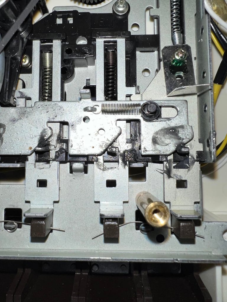
Interior mechanics
The interior of this datasette is VERY dirty. There are dust and grease all over. I doubt that this datasetter would operate at all without a proper clean first.
To get a good clean I choose to remove the belts straight away. The first belt, the counter belt, is very easy to remove. It is just to lift the small handle (see circled area held by a small screw driver in picture below) and remove the belt.
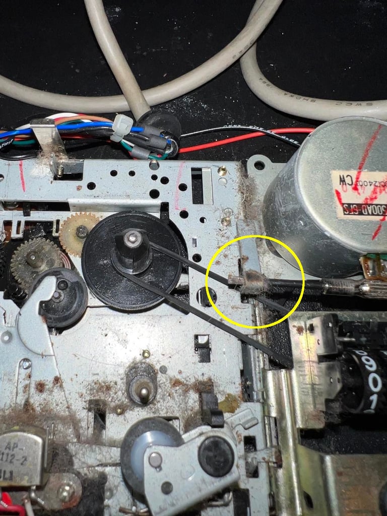
Next is to remove the motor belt. This is also quite easy - if you do it the right way. I first remove the screw at position "1". Then the screw at position "2" is unscrewed about 2/3 of its full length.
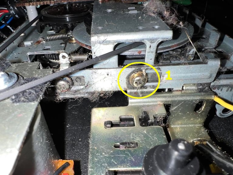


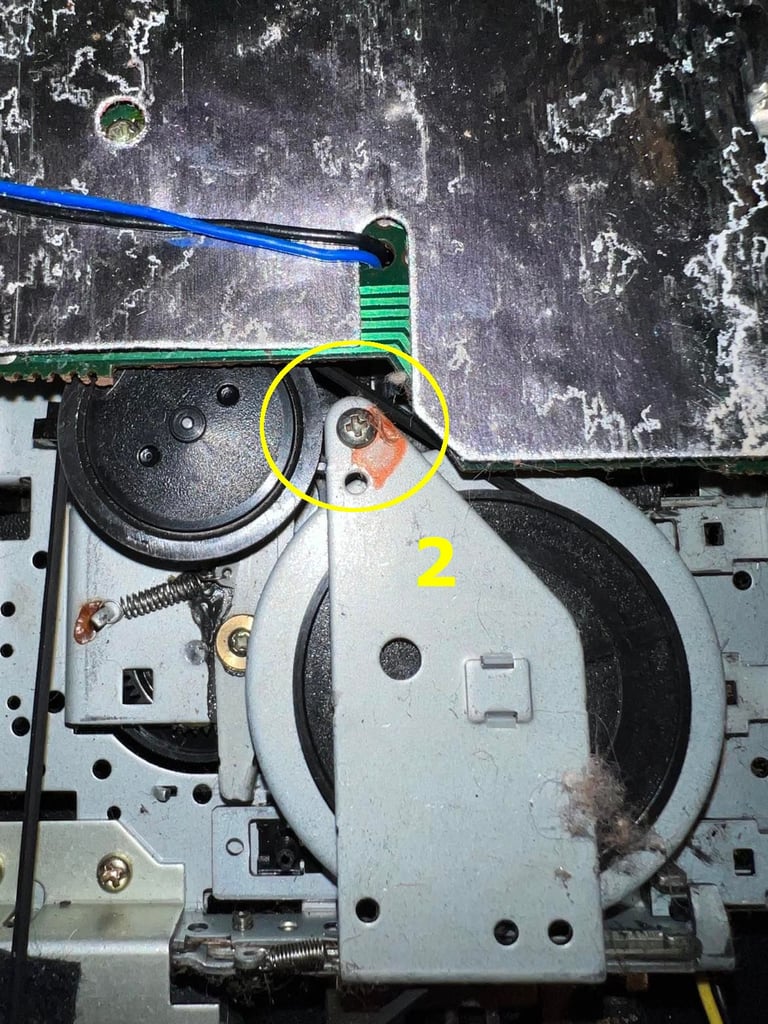
I then carefully lift the metal bracket over the flywheel. This will reveal a small notch where the motorbelt can be released. See picture below.
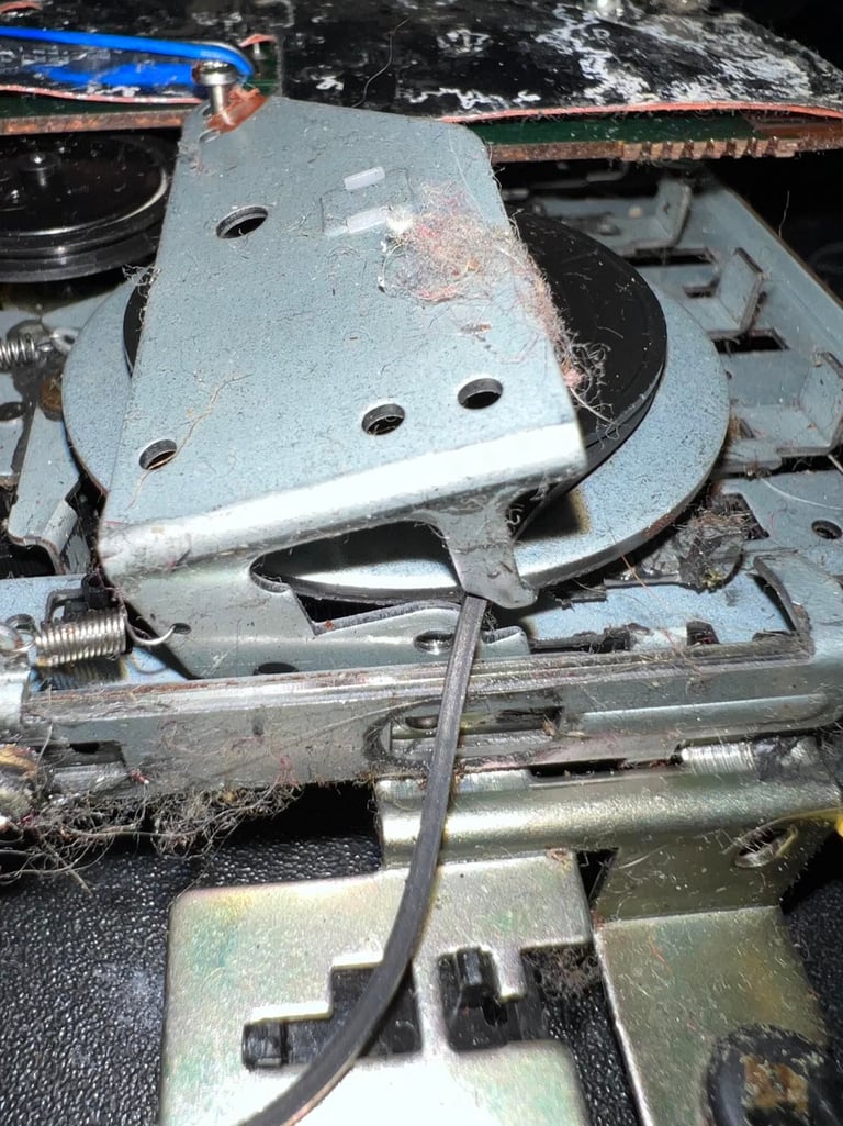
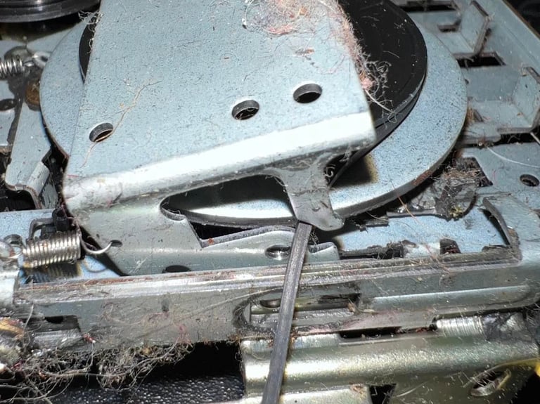
The belts are quite worn out. As you can see from the picture below they have taken shape from the position they have been stuck in for years...
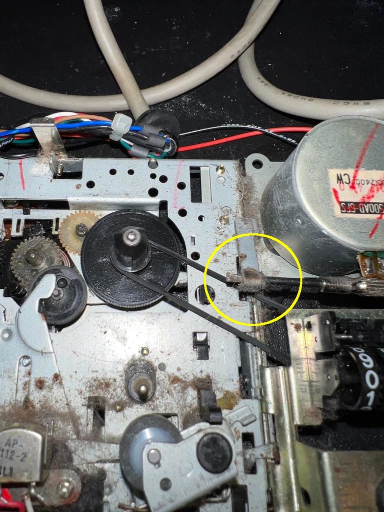
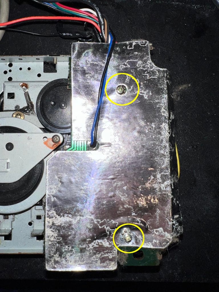
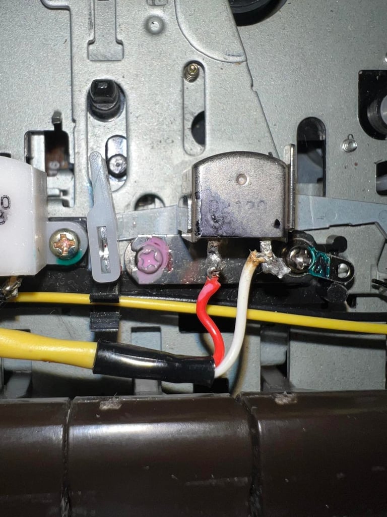
To get to clean beneath the PCB this is also removed. I do this by first removing the two screws - see circled areas below. By gently moving the wires (and I also desolder one of the wires from the little contact below) I can now get access beneath the PCB also for cleaning. Note that this contact is a bit corroded - I´ll deal with that later.
The backside of the interior is cleaned thoroughly with isopropanol on a Q-tip. All of the old grease is also removed and replaced with new grease. The picture to the left show the interior cleaned before new grease is applied. The picture to the right show the interior with the grease applied.

By using the glass fibre pen the small contact below the PCB is also cleaned. I now see that this is only some light surface corrosion - so no big deal. But it´s good to clean it anyway.

The front of the interior is also cleaned with a paint brush, isopropanol and Q-tips. Oh my... this one is so dirty. But I´m quite satisfied with the result - it´s now way cleaner than initially! Notice that I at this point also replace the belts. This is because it´s way easier to clean parts such as the capstan and pinch roller when the belts are in place.

Replacing the belts
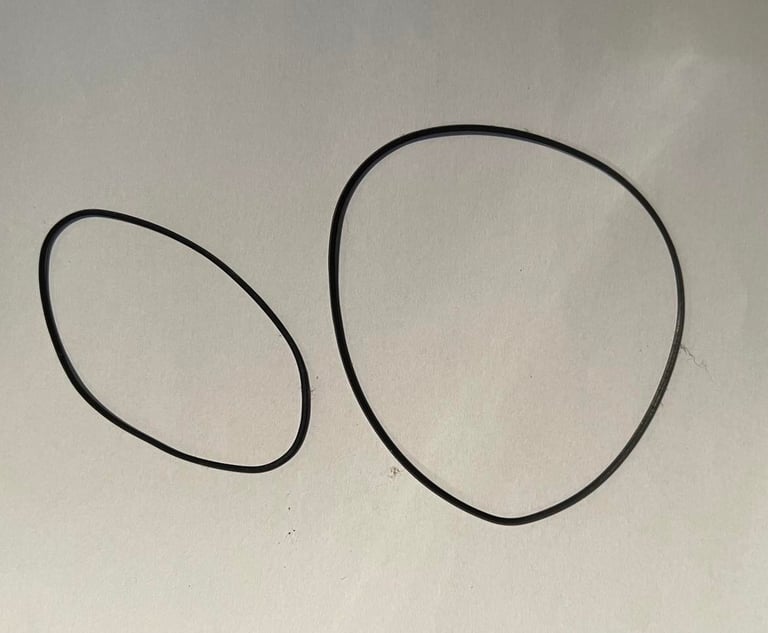
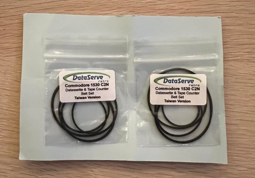
This is probably the most important part in a successful datasette refurbishment. The belts are old and worn out - likely between 30 to 40 years old. To replace the belts I simply do the operation as described in the previous chapter - just in reverse order.
But it is important to use the correct belts. There are two versions of the Commodore datasette in a "belt perspective"; the Taiwan and the Japanese version. This datasette is the "Made in Taiwan" version so these are the belts I will use.
I order my datasette belts from DataServe-Retro.

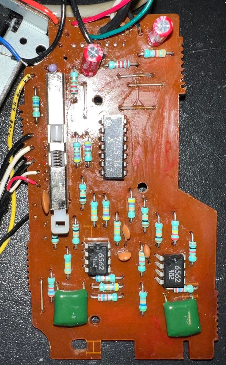
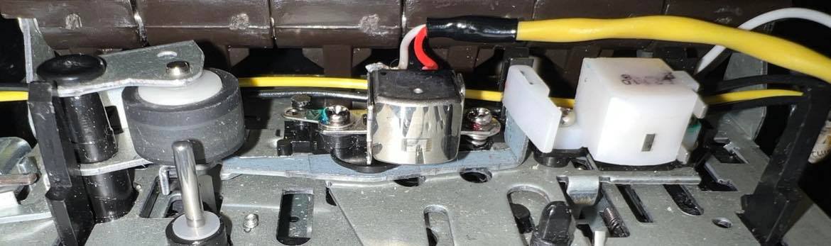
PCB and electrolytic capacitors
The PCB looks to be ok and free from corrosion. It´s a bit dirty, sticky and some flux residue but it looks to be undamaged. The PCB is version NP-090N.
There are two electrolytic capacitors on this PCB; 2 x 47uF [10V]. I replace these with quality Wurth Electronics, but I use a slightly different voltage rating of 16V. This doesn´t matter anything as long as you use a slightly higher voltage rating. The front of the PCB is also cleaned with isopropanol. There are two OP-Amps chips on this PCB - each chip containing two OP-Amps. I´ll use these later when checking (and possible adjusting) the azimuth on the read/write head.
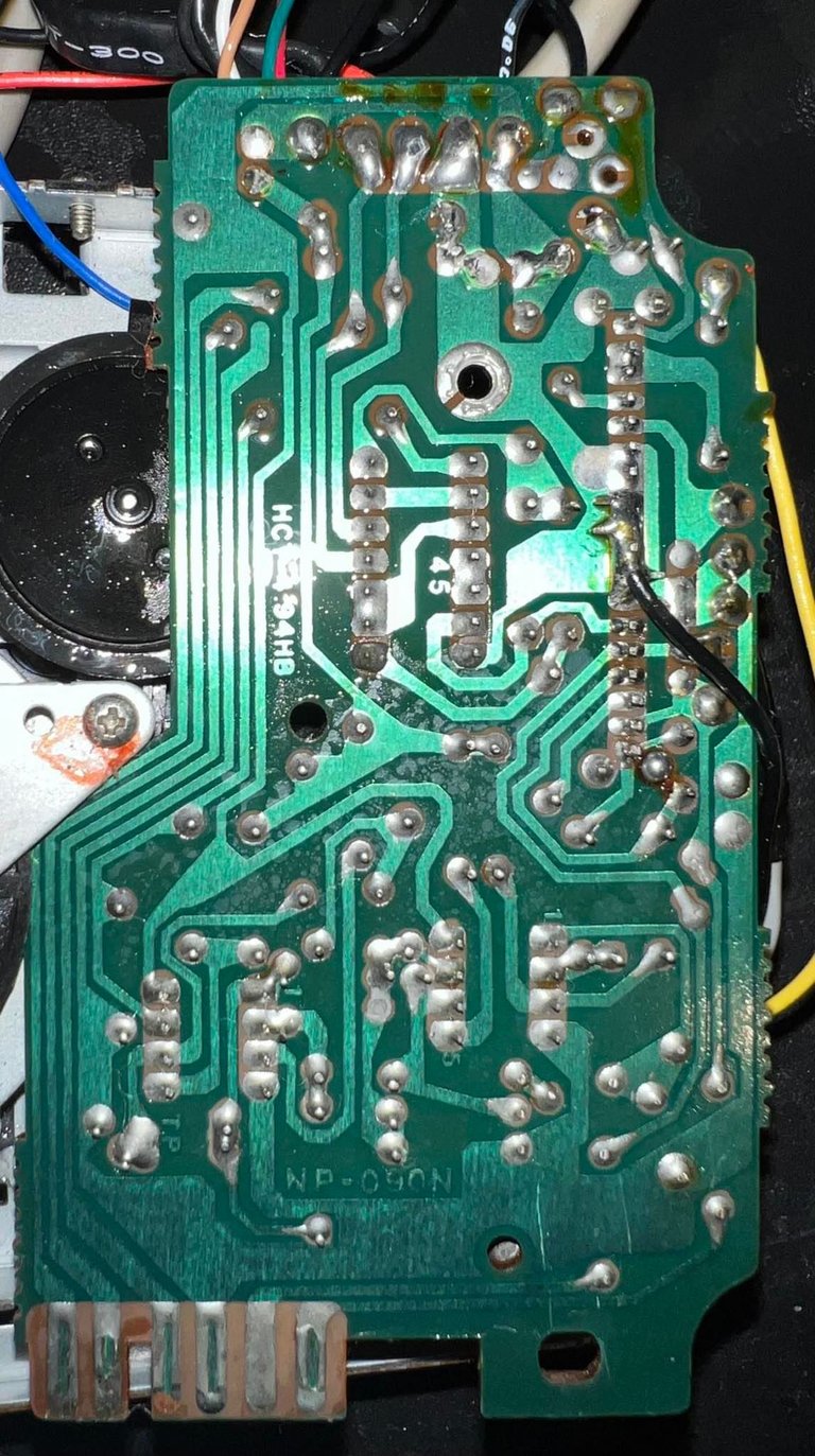
Backside of the PCB is also cleaned with isopropanol.
Initial testing and repair (?)
After replacing the belts I do a quick sanity check to see if the datasette operates at all. And it does. But... there is something strange going on... which I´m not really sure is due to misalignment, bad tapes, broken parts or something else.
The situation is as following:
When playing an original tape it will load successfully about 70 % of the time. So with the same tape it works ok 70 % of the time and fail 30 % of the time
It never fails in the start of loading. 100 % of the playback successfully identifies the program name and starts loading. Failing always happens after it has been loading for a while.
Some possible faults scenarios:
R/W head is misaligned
Tape counter mechanism seem to "slow down" the motor
Corrosion on the read/write head
The flywheel is not free to rotate as it should
R/W head misalignment
I use the oscilloscope to verify that the R/W is properly aligned for tape playback. It´s a bit out of alignment, but it´s quite marginal. Nevertheless, now the R/W should be ok in regards of alignment.
Result: Some improvement, but I´m not satisfied. The "load successfully" rate is increased, but to me this is not good enough.
Tape counter mechanism seem to "slow down" the motor
During playback I notice that the counter is a bit "jagged" while counting. First, I think this is due to some dust stuck in the gears and the mechanism is improved a lot after the removal of this. Nevertheless, I still see that the counter mechanism seem to "slow down" the motor mechanism. I remove the tape belt completely to free the motor. The hope is that is the the reason why a tape sometimes load and sometimes not.
Result: Argh... So disappointing. I can´t see any improvement at all. At I really think that is strange? Nevertheless, it is a fact. It did not fix the problem.
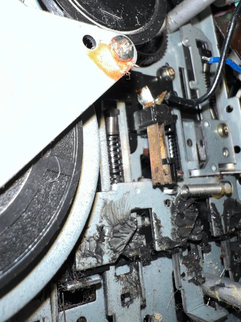
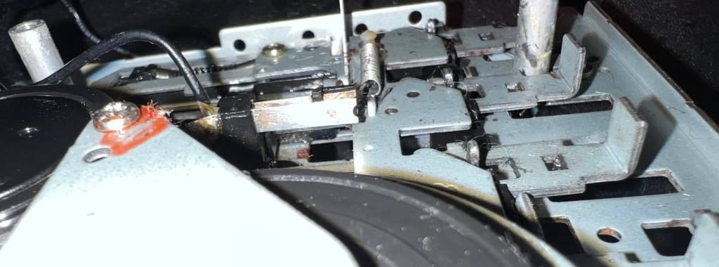
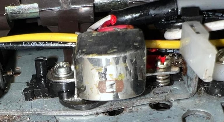
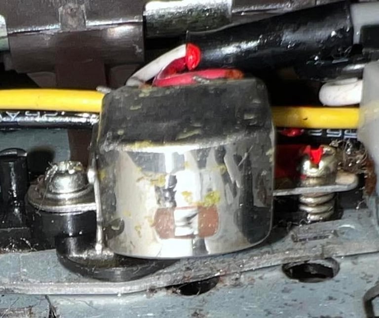
Corrosion on the read/write head
This probably sounds more severe than it is. There are some corroded areas on the R/W head. This is not optimal, but I really don´t think that this is the problem. The reason for that is that if the R/W head were broken or damaged due to corrosion, I thin that the tests and faults should be more deterministic - and not failing at random. But I could be wrong. So I change the R/W head with a known good working. This operation is easier than it sounds. It´s just to remove one screw completely and the adjustment screw partially, then desolder/two wires. Picture below shows the R/W head with the corrosion.
The "new" known working R/W head is re-aligned using the oscilloscope.
Result: No real change. It´s becoming a bit hard to say if it´s improved or not. But, the thing is that is didn´t fix the problem. Some tapes still load successfully some times and some times they don´t... why?!
The flywheel is not free to rotate as it should
The flywheel needs to rotate freely. If the screw which holds it in place is too tight it could effect the flywheels ability to move. I try to loosen the screw a bit to see if this helps.
Result: No change.
Conclusion and plan forward
Even if the datasette playback have improved, I am still not satisfied. Also, just to mention it, but I have tried to clean the contact, different tapes and also different C64s. But the results are still the same: about 70-80 % of the times a tape loads successfully. Maybe this is not too bad, but in my opinion (and experience) a known working tape should load 9 out of 10 times.
Now what? I still think that it is possible to fix this, but I choose to replace the interior mechanics with a "new" one from another datasette. This "new" datasette has a beat damaged exterior chassis, but the interior is very good. I plan to fix the "old" interior at some later time - or use it for spares. So let´s change the interior!
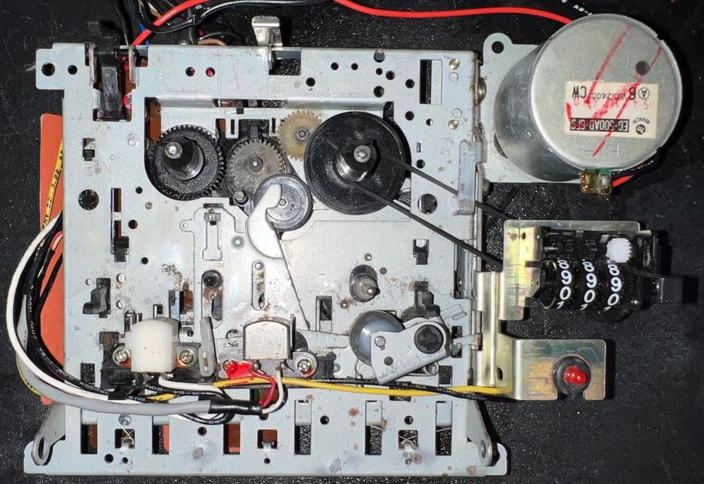
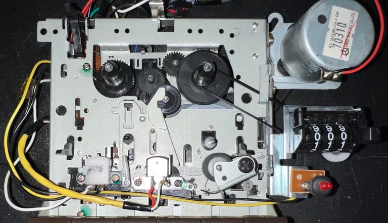
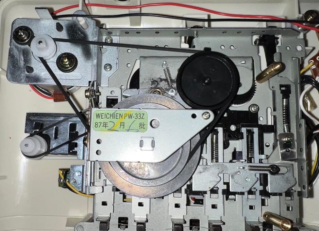
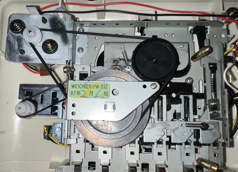
Interior mechanics - Second edition
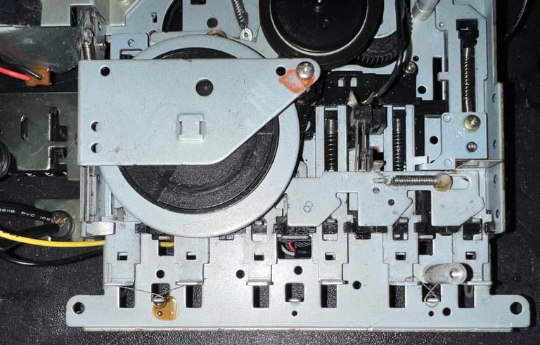
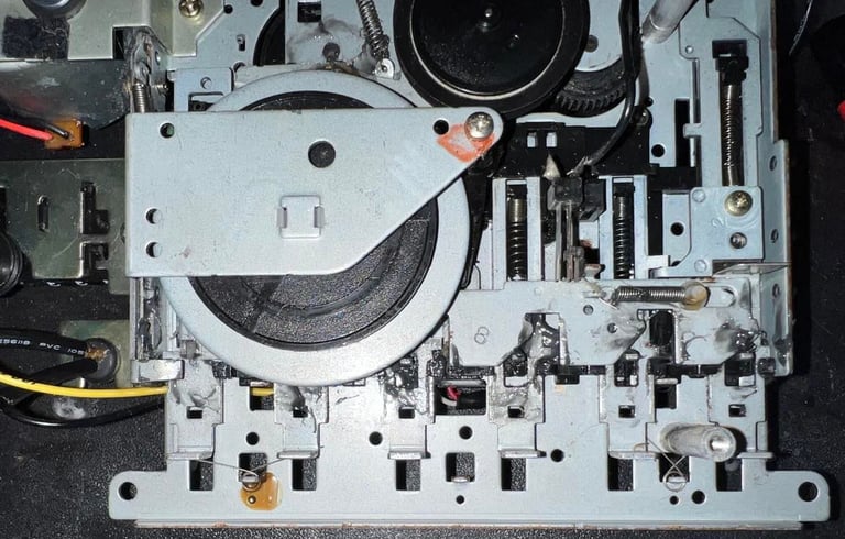
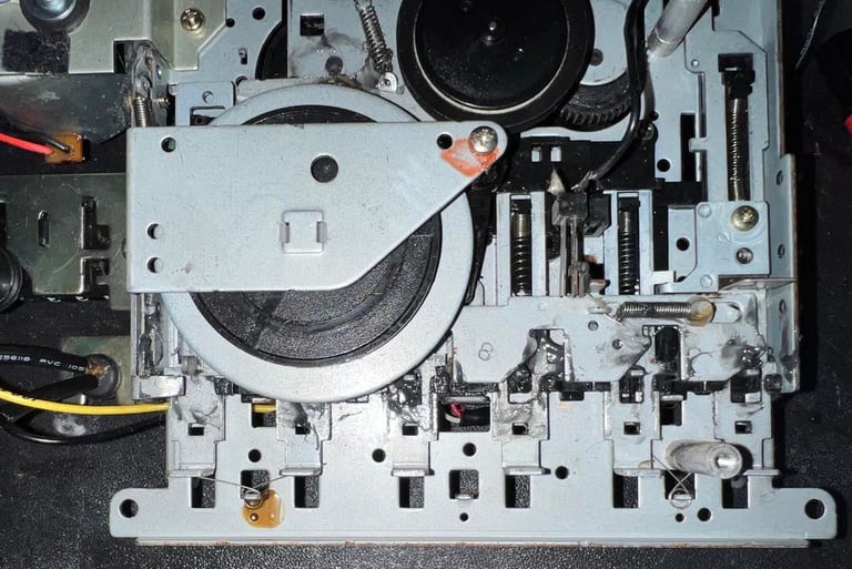
I have a very nice interior from a different datasette that I choose to use in this one instead. This interior has already been cleaned by me earlier. Cleaning has been done in much the same way as described earlier, but this new interior was never so dirty as the original one which were in this datasette.
Below are two pictures; the first shows the front side of the interior and the second shows the back side. Please note that the belts here are now the new ones - so the belts have been changed to the same new ones. I think it´s hard to understand that this interior is almost 40 years old. It looks new?!

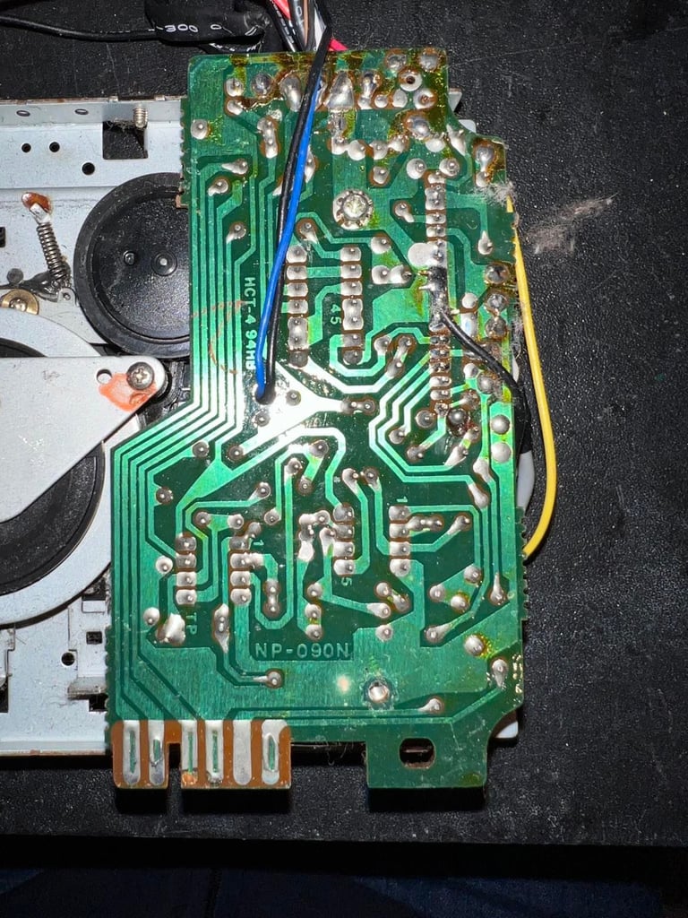
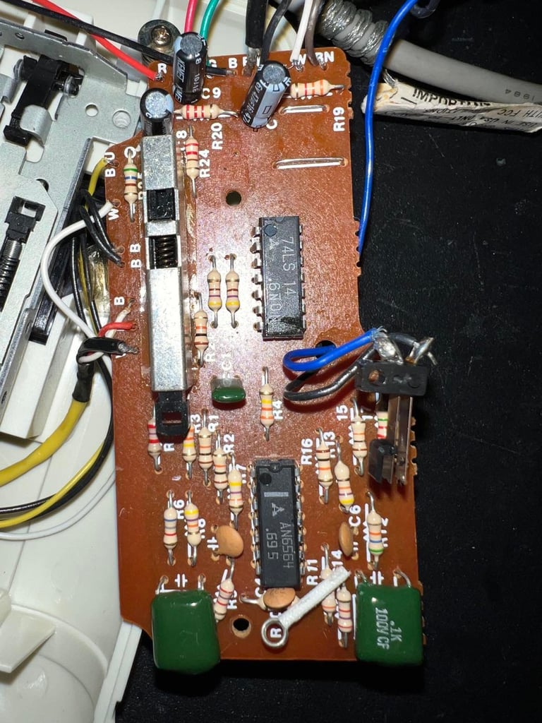
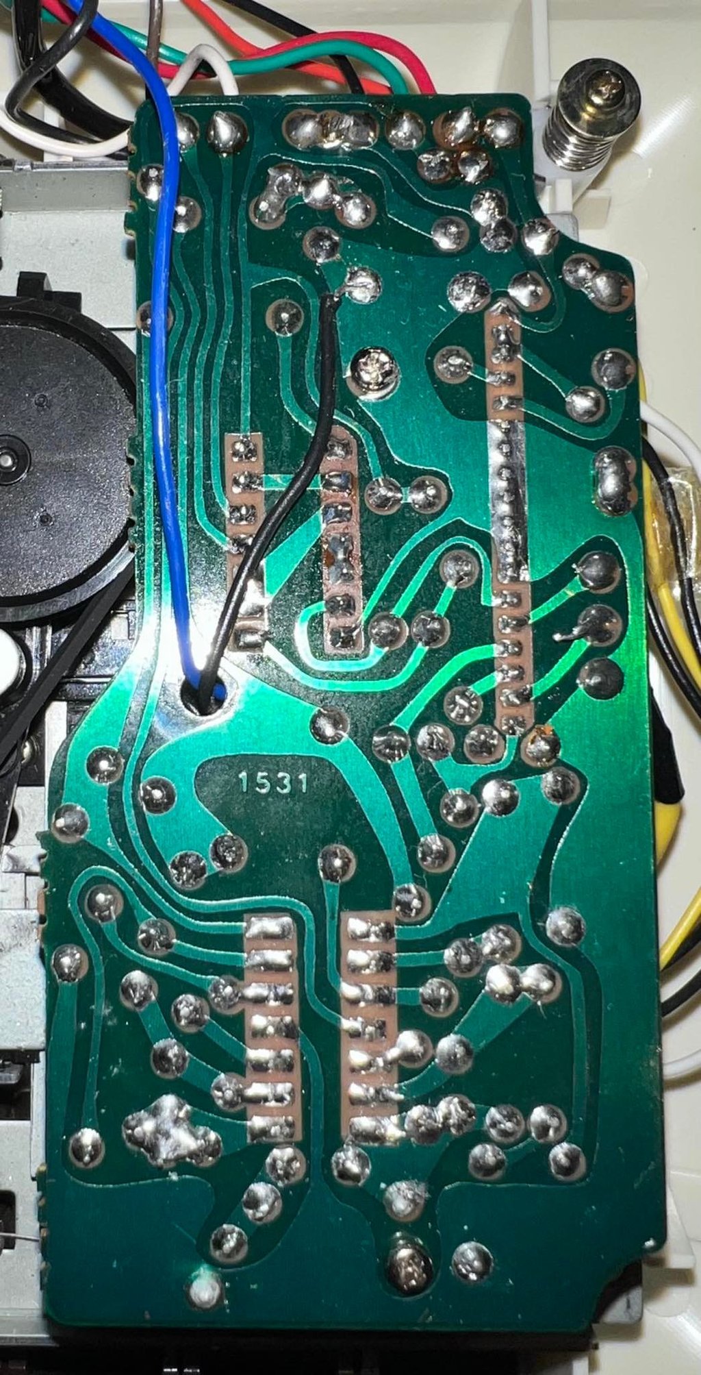
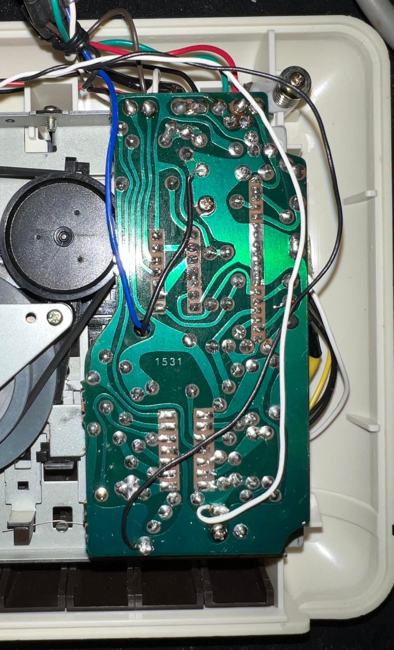
The PCB is also from the "new" datasette and is assy "1531". This PCB have also been checked, cleaned and recapped. In difference to the old PCB this new one have three electrolytic capacitors (47uF / 16V) instead of two. These three have been replaced with new Kemet capacitors by me previously. Below are two pictures; one showing the front of the PCB (also with the new capacitors) and one showing the back of the PCB.


Erase head, R/W head, capstan and pinch roller are also cleaned and looks very nice. In this R/W there are absolutely no signs of any corrosion.

I add some grease to some of the interior parts to make sure the move smoothly without too much friction.

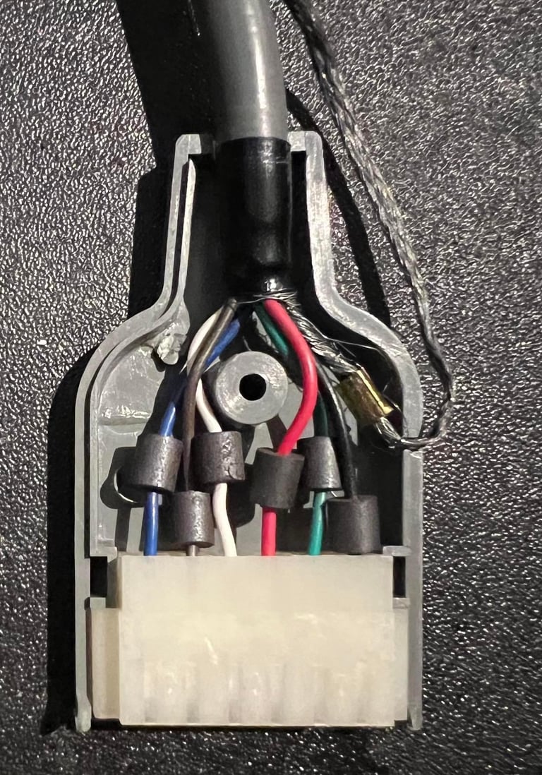
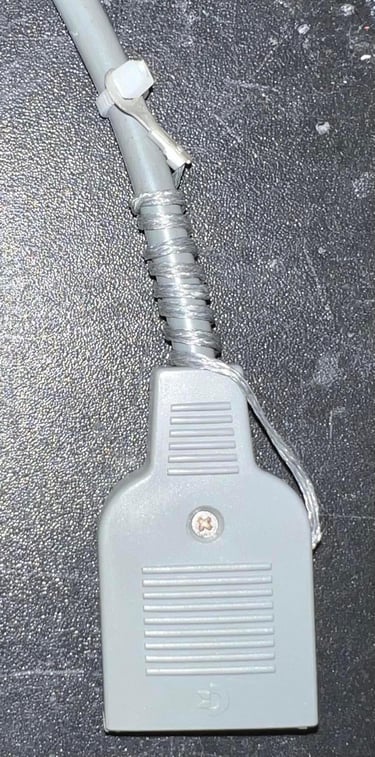
Cable
The cable is checked and cleaned. Also the ground wire is twisted around the cable and fastened with a cable tie. The reason for this is that this ground wire is not used by the C64 at all (it is some legacy wire). And there is a good chance that this wire, by accident, get into the user port and short cuts the C64. The contact is also cleaned with contact cleaner.
Read/write head alignment
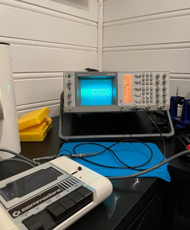
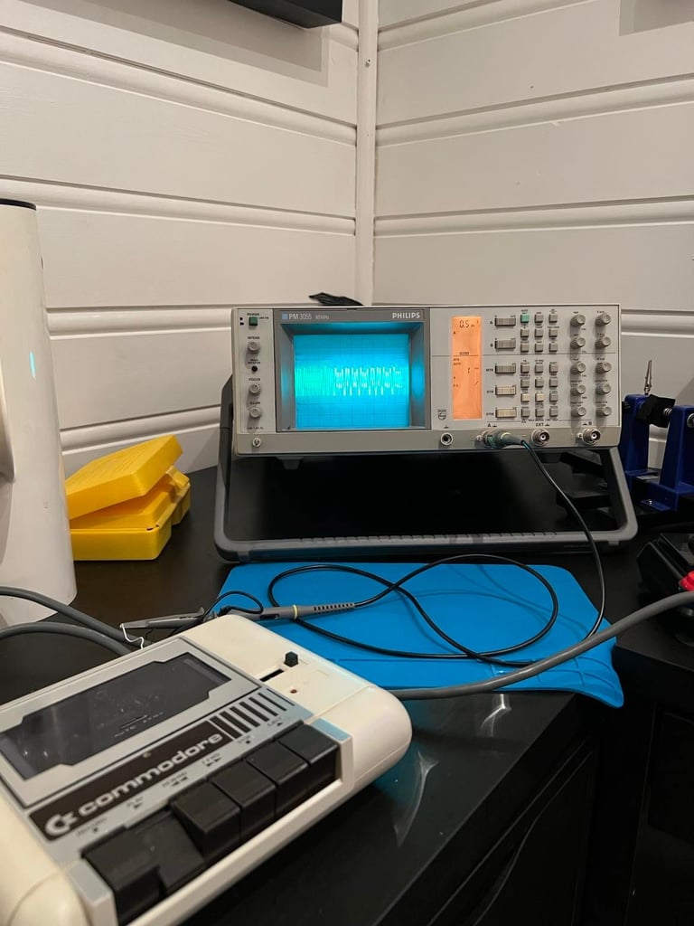
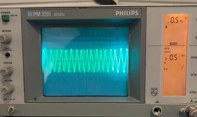
To make sure the read / write head is aligned for optimal playback I make use of my oscilloscope. The goal is to adjust the position of the R/W head to the maximum amplitude with the oscilloscope, verify the signal with the cassette azimuth software and lock the screw with some nail polish. Note: to make sure that the screw is properly aligned the datasette must be assembled completely when doing the adjustment.
In order to use the oscilloscope to get at proper reading of the amplitude I solder on two wires to the PCB. The white wire goes to the 2nd stage of the OP-Amp chain, and the black wire goes to ground.

The reason for using the 2nd stage in the OP-Amp chain is that this is the stage where the signal is an analog amplified signal from the R/W head, but it has not yet been saturated to be used as an digital signal. Now, I connect the oscilloscope to these two wires. And while playing a known good tape (original!) I adjust the azimuth screw until I reach the maximum ampltitude.
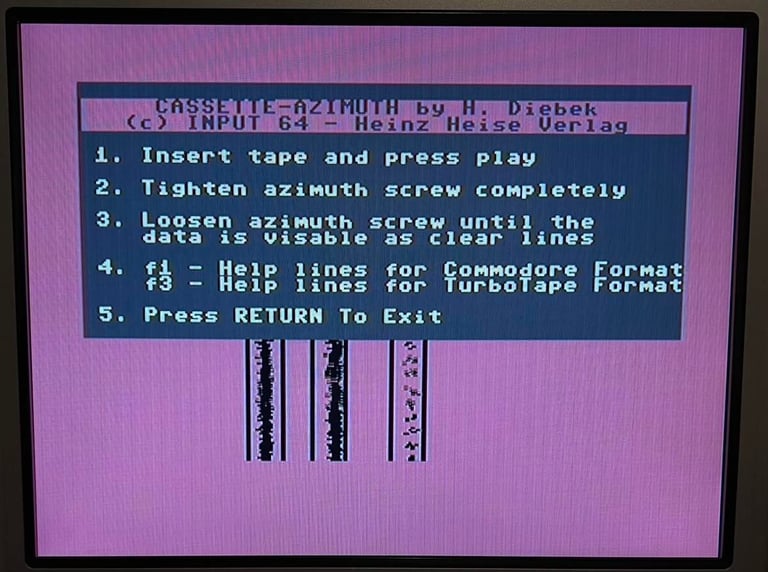
After I have adjusted the screw to reach maximum signal amplitude I run the Cassette-azimuth software on a C64. This is to verify that the adjustment is in fact correct. You could argue that you could skip the oscilloscope stage to find maximum signal, which is true, but my experience is that this is way harder. My opinion is that the most correct and efficient way is to use the scope for adjustment and the cassette-azimuth software for verification. Below is a picture from the cassette-azimuth software. It should show three lines with limited scattering - which is does.

As a final step I add some nice nail polish (borrowed from my daughter) to lock the screw in optimal position.

Final testing
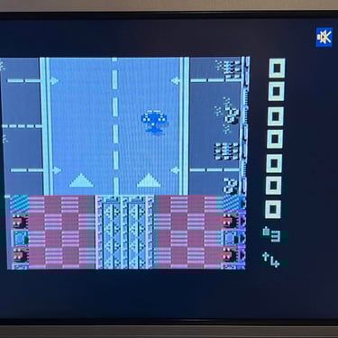
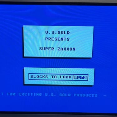
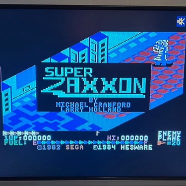
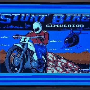
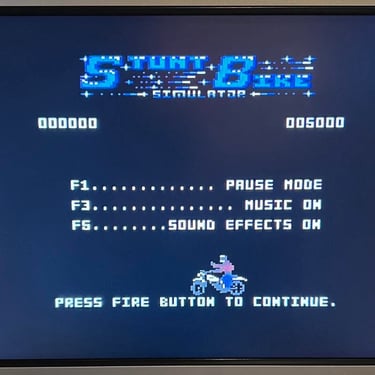
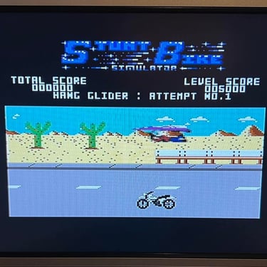
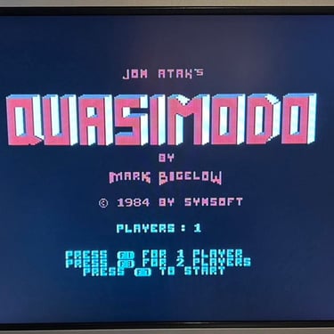
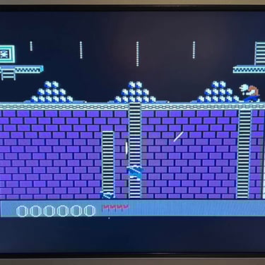
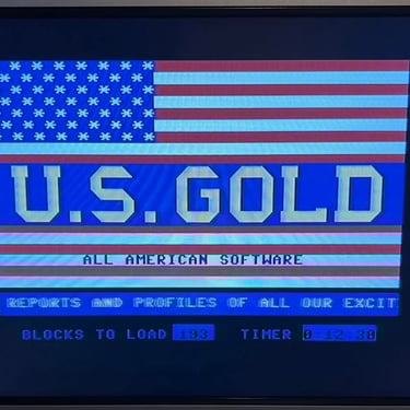
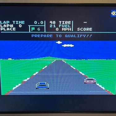
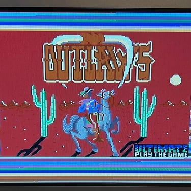
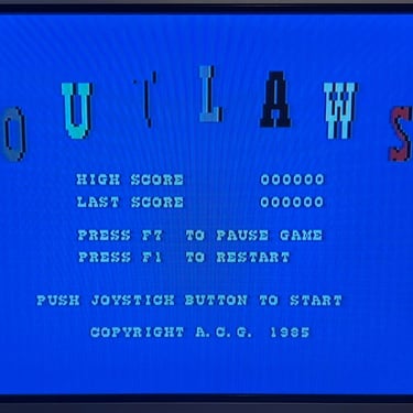
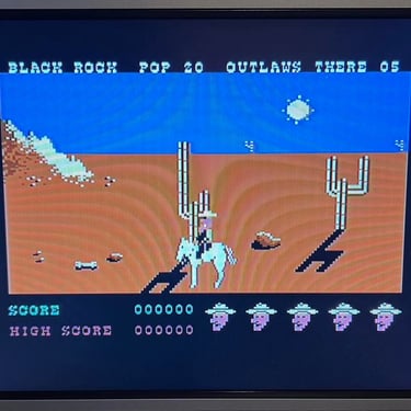
I choose seven (!) games to test the datasette. This is way more than I normally do (which is to use three games), but I need to rule out that there is a problem with the datasette related to the plastic chassis and marginal / bad tapes. All of these seven tapes are old, but they are original. That means that they are recorded professionally. Also, I know that these tapes are ok and should load successfully. Note, saying that an old tape which is 30-40 years is "known working" can be hard as these are continually degrading.
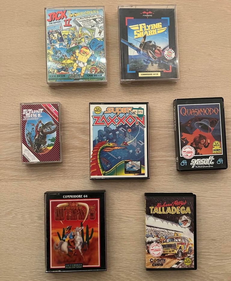
Below is a gallery with pictures from the testing. All of these seven tapes load successfully without any issues on all load attempts That is actually a bit more than I expected - I think that if such old tapes loads successfully 9/10 times it should be considered as a "success".


Final result
"A picture worth a thousand words"
Below is a collection of the final result from the refurbishment of this datasette. Hope you like it! Click to enlarge!
Banner picture credits: Evan-Amos