

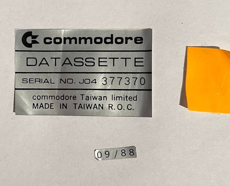
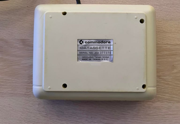
1530 (C2N)
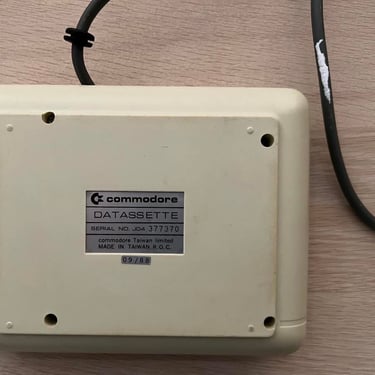
Ser. No. 377370
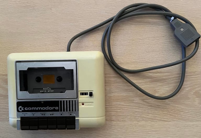
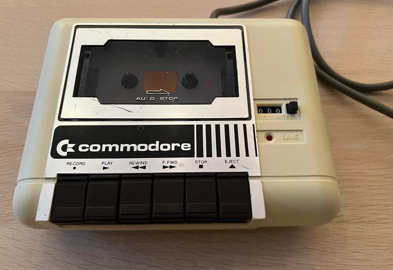
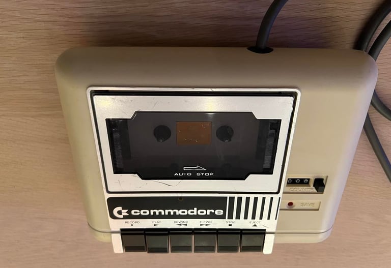
Starting point
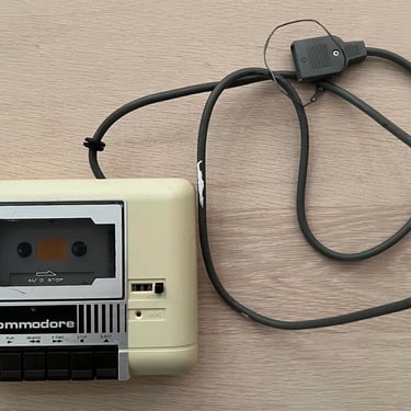
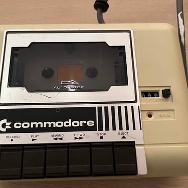
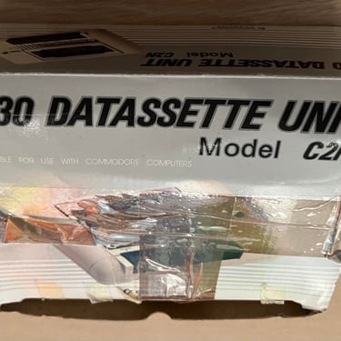
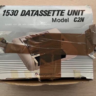
This datasette already looks very nice I think. There are some grease and scuff marks, and the cable is not properly attached but otherwise this looks good. Looking forward to refurbish this datasette! Below are some pictures of the datasette before the refuirbishment starts.
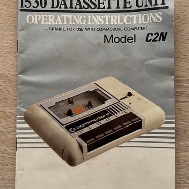
Also, the datasette comes with the original box and user manual. The box doesn´t look too god with the tape and marks, but the user manual looks a bit better.
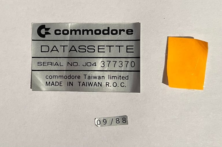
I see that there is a small sticker "09/88" - I guess that means that the datasette is assembled September 1988.
Refurbishment plan
To refurbish this 1530 datasette the plan is to do this trough the following steps:
- Clean and remove stains from chassis
- Clean the interior mechanics
- Check cable and replace strain relief
- Replace motor- and counter belts
- Check PCB for corrosion and replace old electrolytic capacitors
- Adjust head for optimal tape reading
- Verify datasette operation by testing
Note that several of these steps are done in parallell.
Exterior chassis
The chassis is divided in the top- and bottom cover. This is easy to do by just removing the four screws at the bottom of the datasette. As the pictures shown above the datasette is not at all very dirty. Nevertheless, it will need a cleaning.
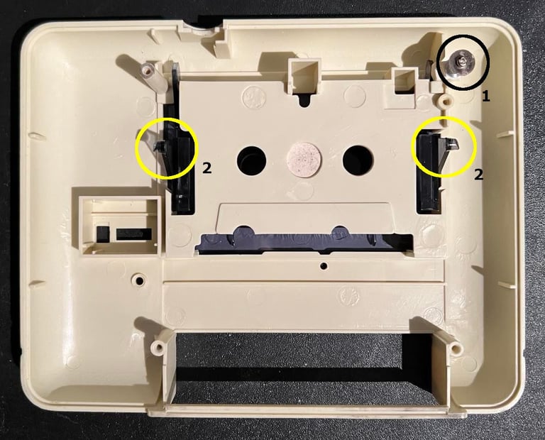
First, the top lid is disassembled from the top cover. This is done by removing the screw, washer, spring and plastic spacer from underneath the top cover (see circle "1"). Then the two hinges are carefully pushed toward the center of the lid (circle "2") and the lid is pushed forward and out.

Before all parts are cleaned the stickers are removed to make sure they are not destroyed by liquid. To remove the stickers I (carefully) use some heat from a hair dryer while gently lift the stickers with a sharp knife and with a pair of tweezers.
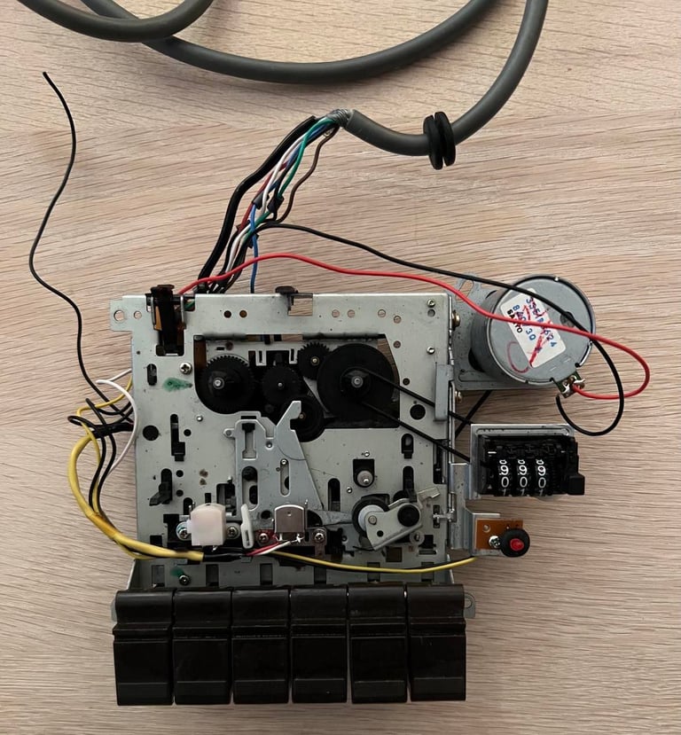
Interior mechanics
The interior looks also quite promising. I can´t see any major corrosion and the mechanics looks to be intact. But there is a wire which is loose(?). It is soldered to the PCB, but the other end is isolated. And it doesn´t seem to part of the main cable to the C64 so I wonder what this is... And I wonder if this works at all, but I will find out.
Below are some pictures of the interior before cleaning (and repairing?).

First thing to do is to remove the six keys. To do this first remove the washer on the right hand side. When this washer is removed the shaft holding all the keys can be removed. Below you find a picture of the position of the washer.
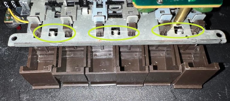
With the shaft removed I turn the datasette upside down. Then I carefully push the three springs out of the small notch in each key. This will make the keys fall out one by one. Picture below show the positions, in circled areas, of these little springs. Note that these springs needs to be handled quite carefully.

There are four areas that are crucial that are cleaned properly:
Erase head
Read / Write head
Capstan
Pinch roller
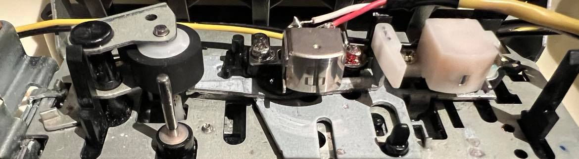
Below is a picture showing the of the position these.
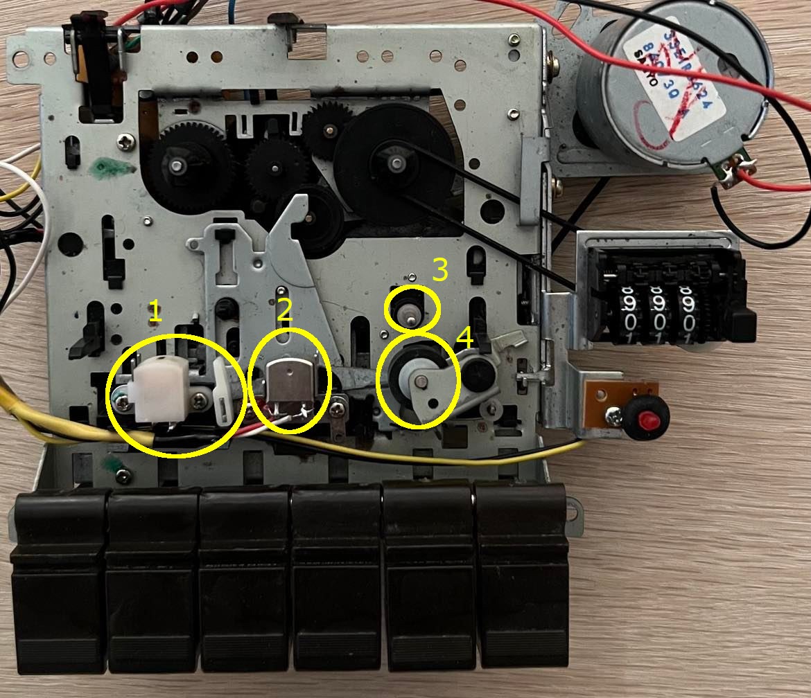

The erase head (1) and the R/W head (2) are cleaned with isopropanol on a Q-tip. The capstan (3) and the pinch roller (4) are also cleaned with isopropanol, but for these two I use a little trick. I connect the datasette to the Commodore 64 and use the PLAY and REW/FF to make the capstan and pinch roller rotate. While rotating I clean these carefully. You can see example of this process in the videos cleaning the pinch roller and cleaning the capstan. Note that these videos are from a different datasette, but the same process has been used for this datasette also.
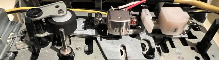
The result of the cleaning is shown below.
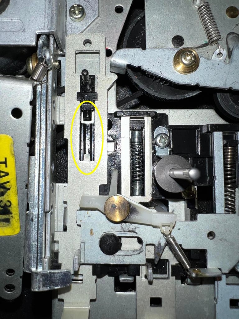
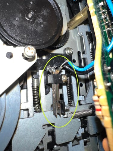
During cleaning and some mechanical testing I notice that the EJECT button sometimes doesn´t get pushed back in position. It doesn´t interfere the operation, just a bit annoying. But after some investigation I see what´s causing it: there is a little spring missing for the EJECT button (behind the flywheel). Well, I don´t have any in reserve, and this is not a big deal I think. But I also remove the (very) small spring between the STOP and EJECT key (see picture earlier) - this will actually "remove" the problem to a great extent. Not a big deal, but anyway... In the circled are in the picture below you can see the missing spring.

Cable
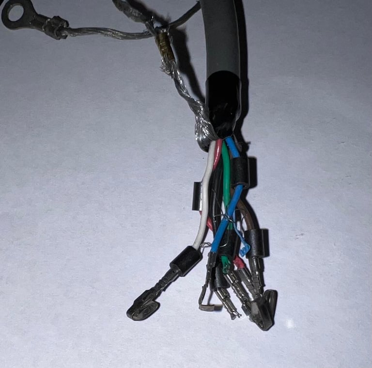
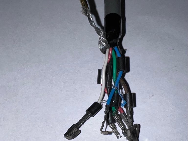
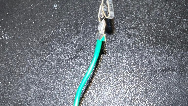
It is crucial that the cable and connector is ok for the datasette to operate as it should. The cable itself looks ok and undamaged, but with closer inspection I notice that one of the pins are damaged. It is the "sense" pin which is damaged. This pin is used for detection, if one of the keys PLAY, RECORD, F.FWD or REW is pressed (source: C64 wiki).

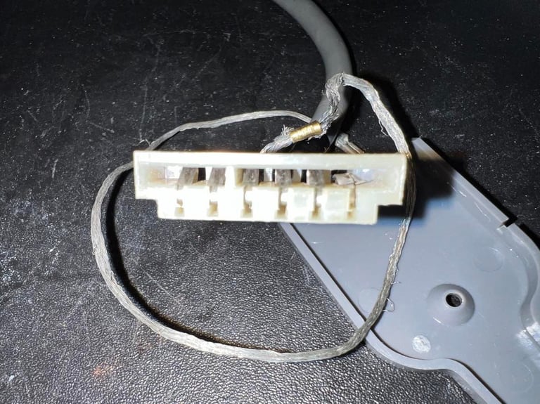
This is the first time I see a pin on a datasette connector that is so severely damaged. This must be fixed. Luckily, I found this great video on Chuch Hutchins YouTube channel. In this video he shows both on how to get new pins and how to replace them. So I will order some new pins from Mouser. It´s not very easy to get the old pins out, but with some patience I manage to get them all out without breaking the casing.
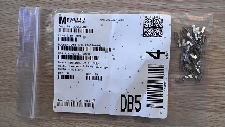
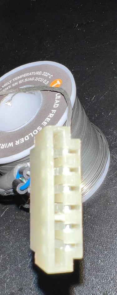
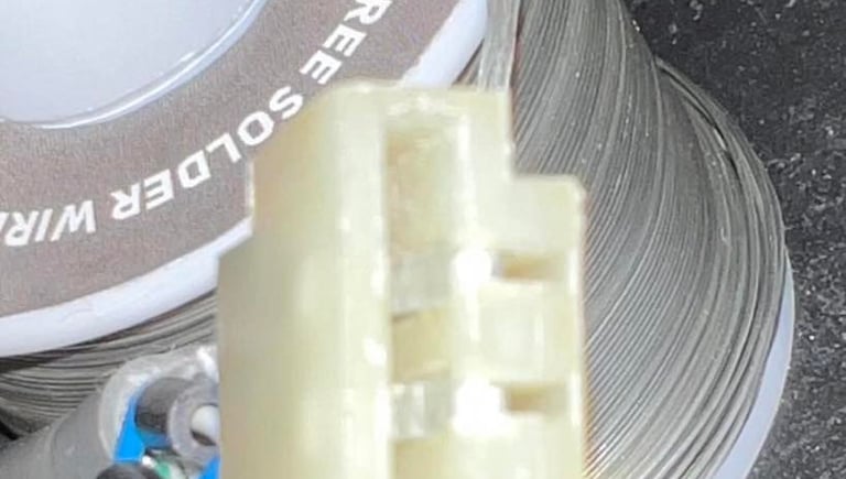
New connector pins received from Mouser:

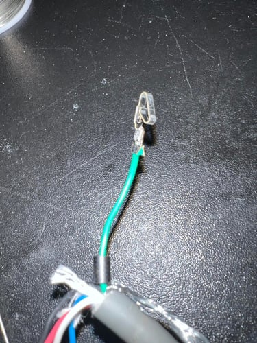
Each wire is stripped and a small amount of solder added at the tip. Then the wire is soldered onto the connector pin. This is done for all six wires (and keeping the ferrite bead on each wire). Below are pictures of; connector pin soldered to wire, all connector pins in place and connector back in casing.
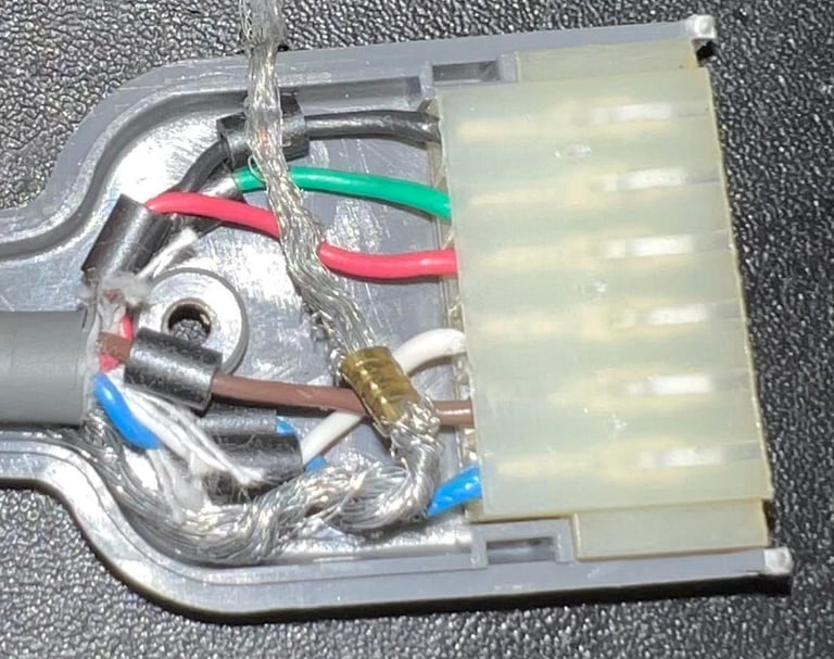
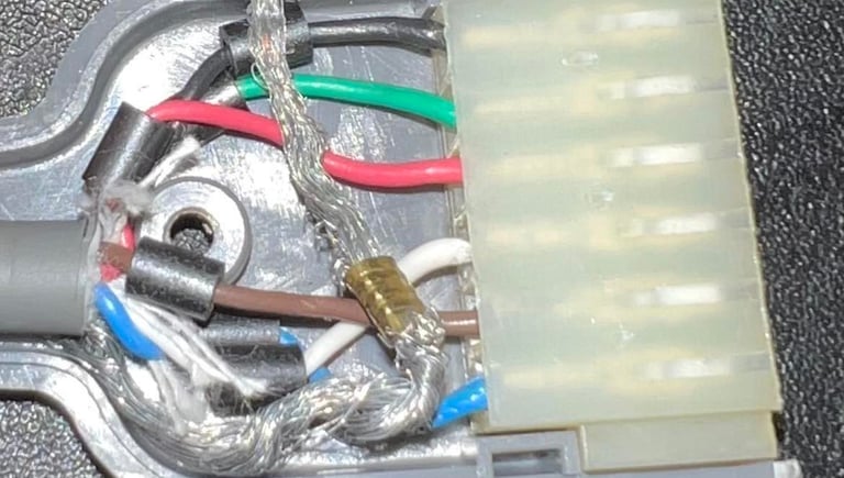
As a last ouch the ground wire is wrapped around the cable. This ground wire is not used in the C64 (this is a legacy wire from older systems). You DON´T want to have this ground wire accidentally end up in the user port of the Commodore 64.
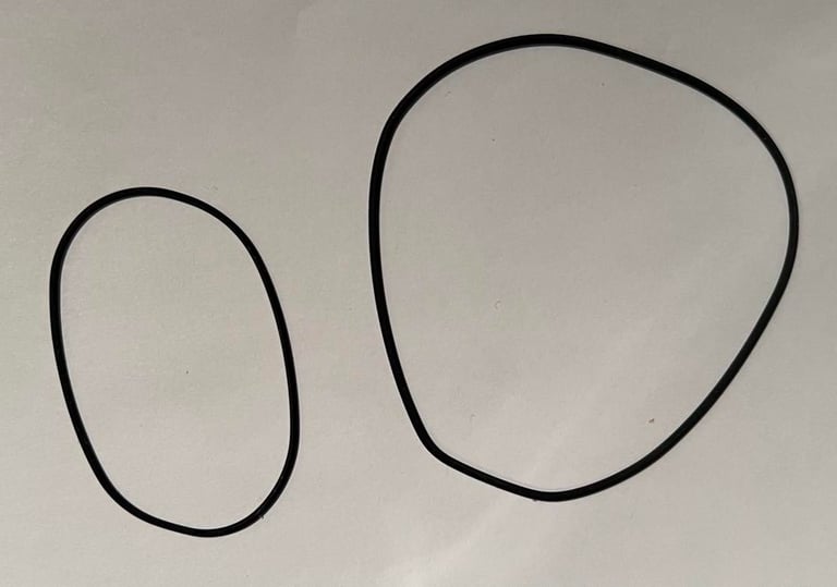
Replacing the belts
Correct, and not worn out, belts are essential for a Commodore datasette to work. After years of storage is normal (close to always) that these belts loose their elasticity and also get deformed. There are two belts in this 1530 (C2N) datasette; one for driving the counter and one for driving the gears from the motor. The former is not critical for the datasette to operation, but in some games it is required to reset the counter and without a working belt you will have problem when finding the correct position after forward/rewind operations. The latter is crucial for the datasette to operate properly. With a worn out belt the gears will slip and you will enjoy several "?LOAD ERROR" message.
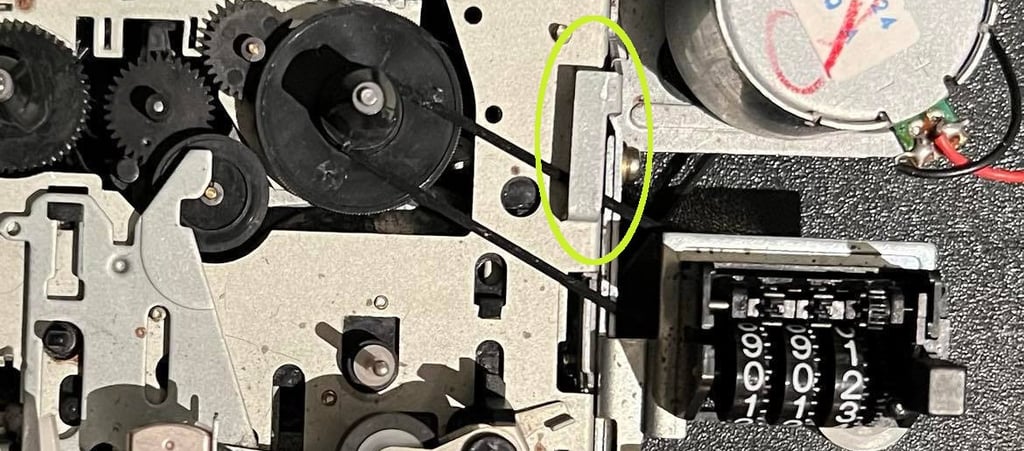
To remove the counter belt it is only to lift the little handle to the left of the counter. Then just remove the belt from the gears. Picture below shows the position of this handle.
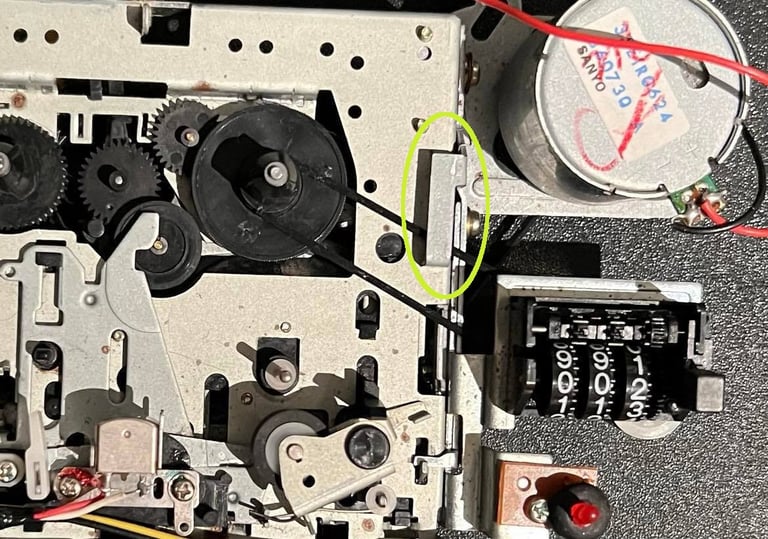
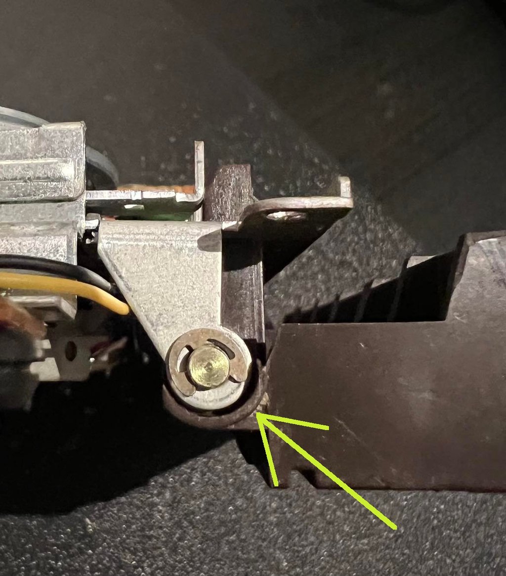
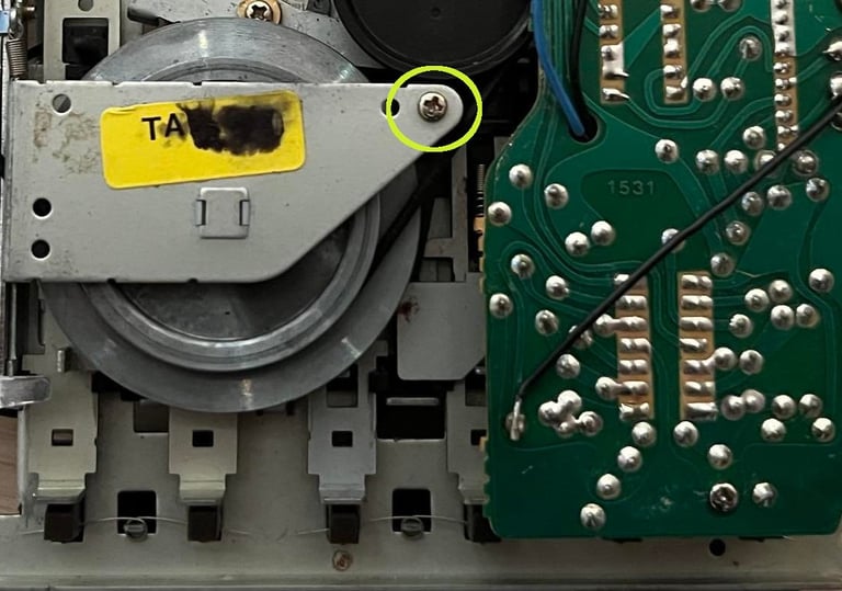
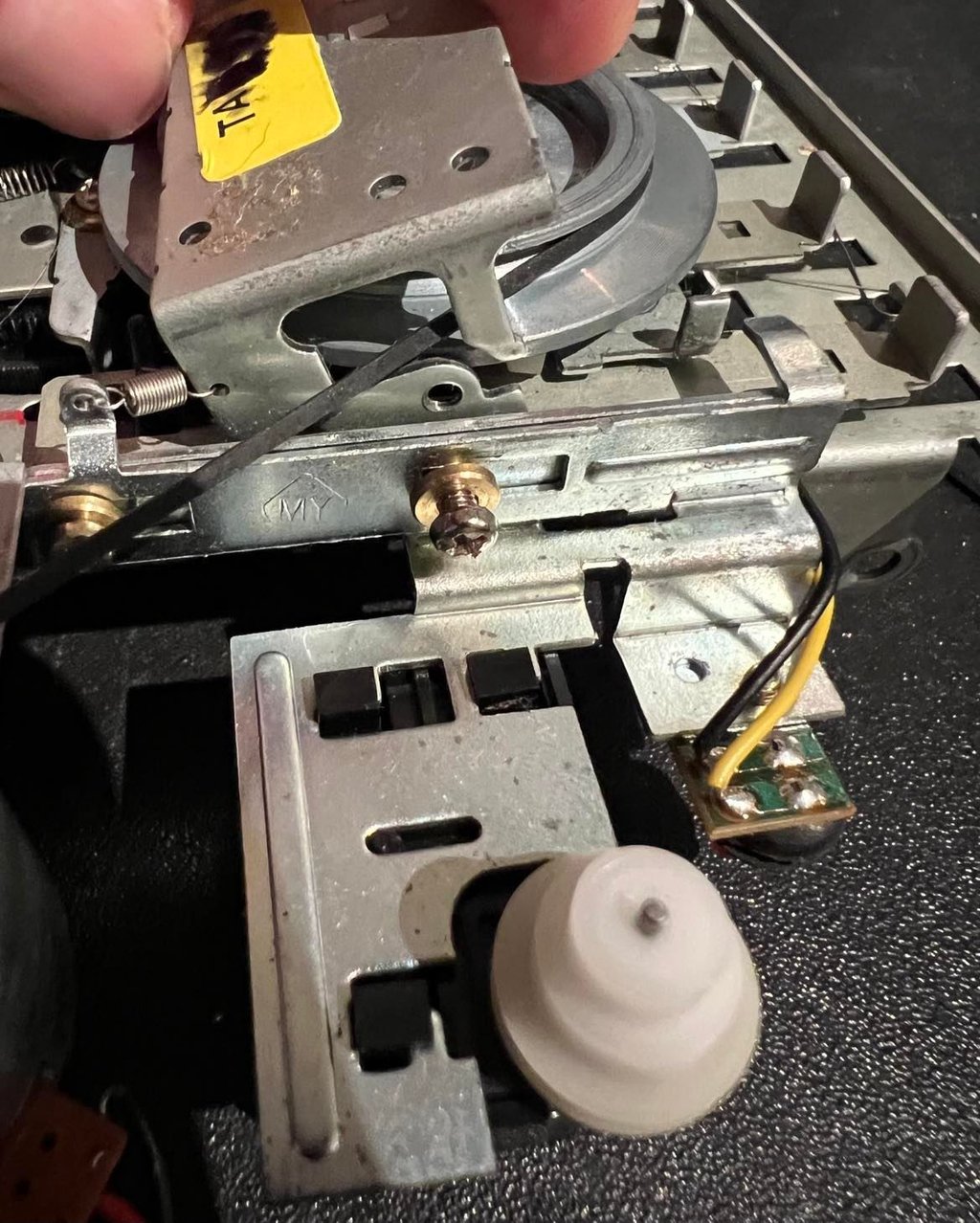
Next step is to remove the motor belt. This is not difficult, but it´s wise to do it as gentle as possible to avoid springs and gears flying all over the place. First I remove (or partly unloose) the screw holding the top bracket. See picture below.
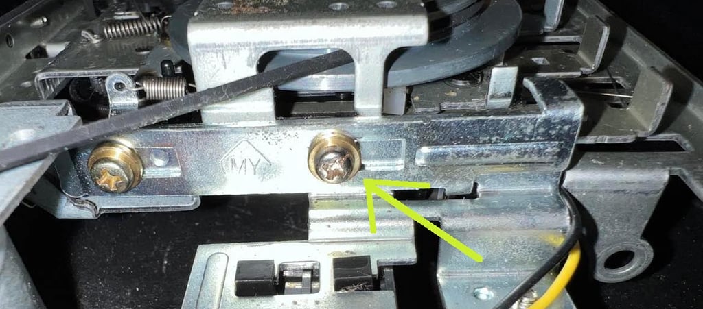
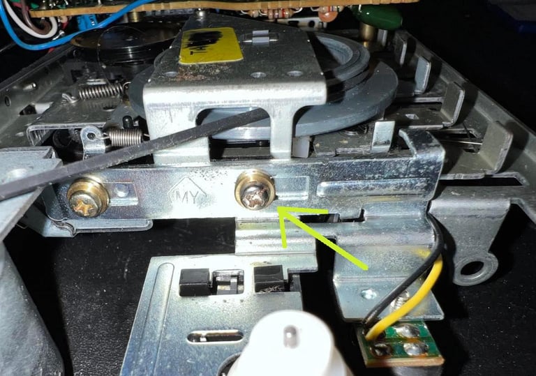
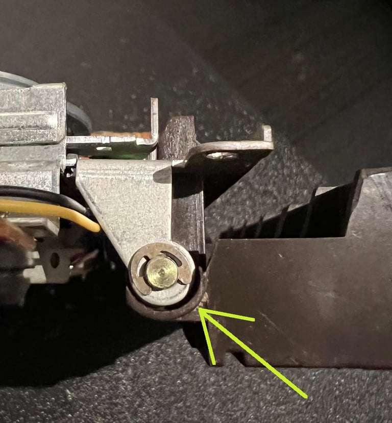
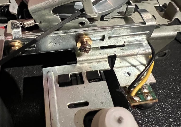
Then the screw on top of the bracket is partly loosened. See circles area in picture below for the position of this screw.
With both screws loosened it simply a matter of gently lifting the bracket - just enough to get the belt out of the notch. See picture below.
Both belts show significant wear and deformation.
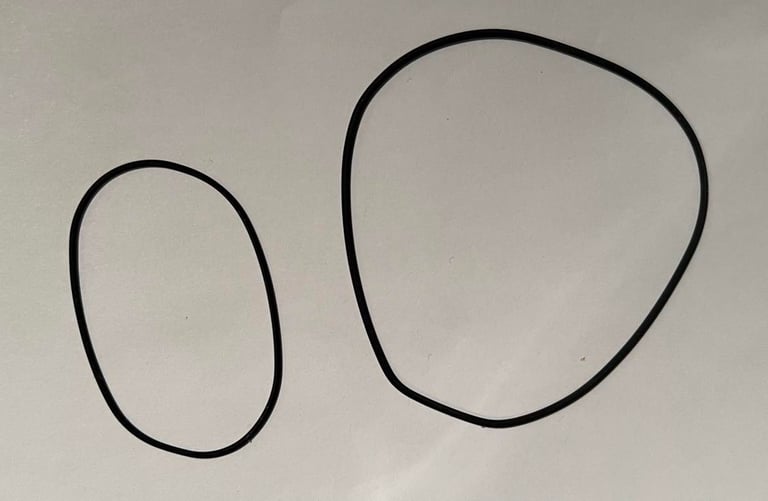
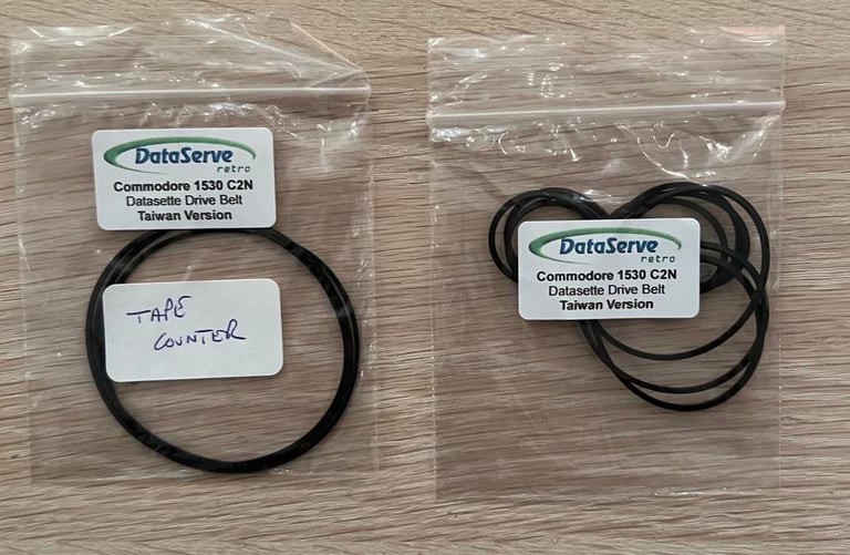
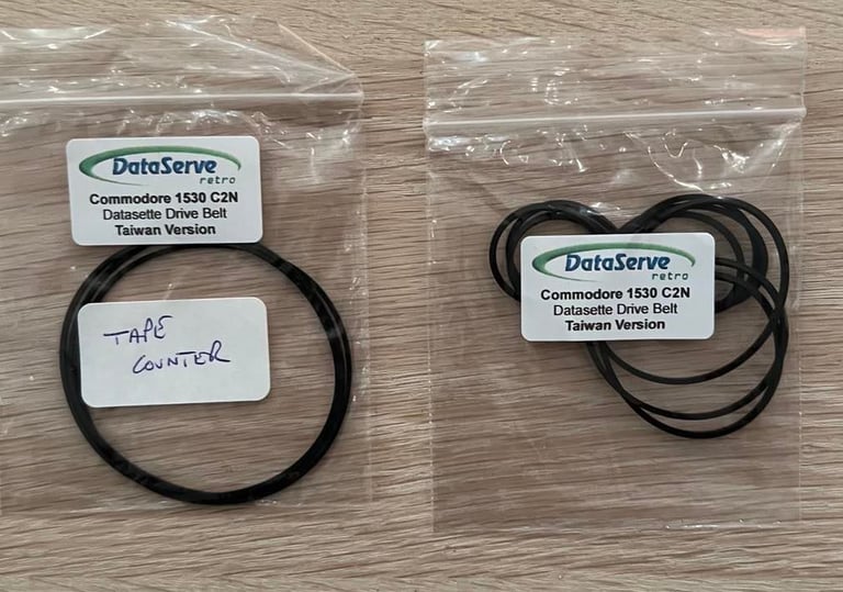
When replacing belts it is important to use the correct size. It´s common to differentiate between the "Made in Japan" and "Made in Taiwan" version of the 1530 C2N datasette. This one is the "Made in Taiwan" version, and I´ve ordered new belts from DataServe-Retro.
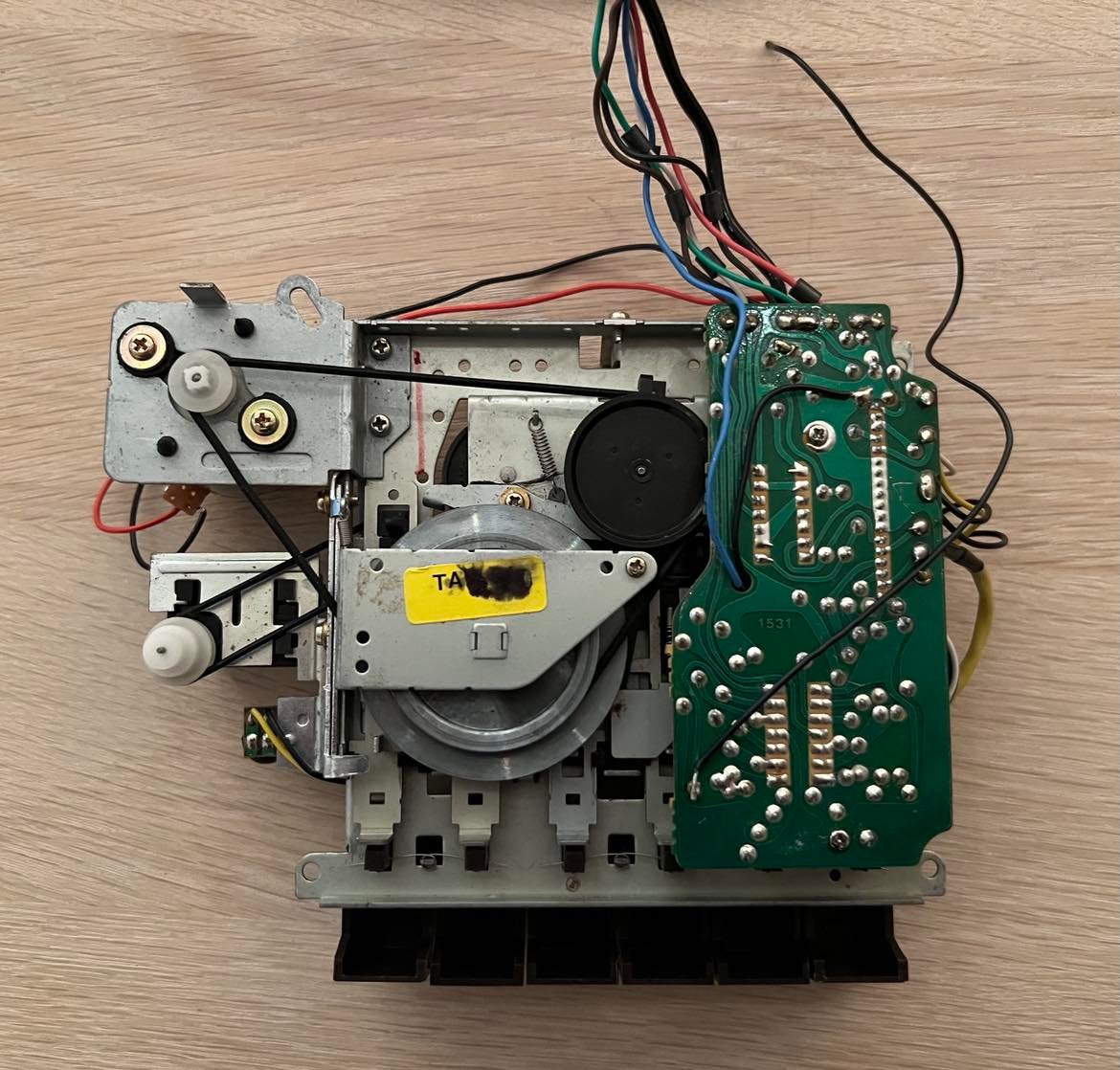
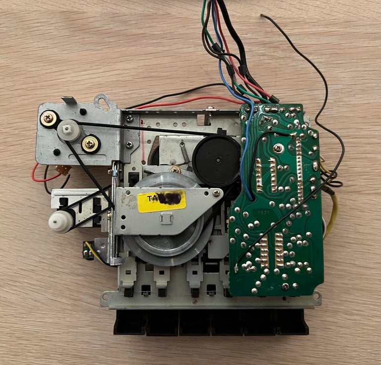
PCB and electrolytic capacitors
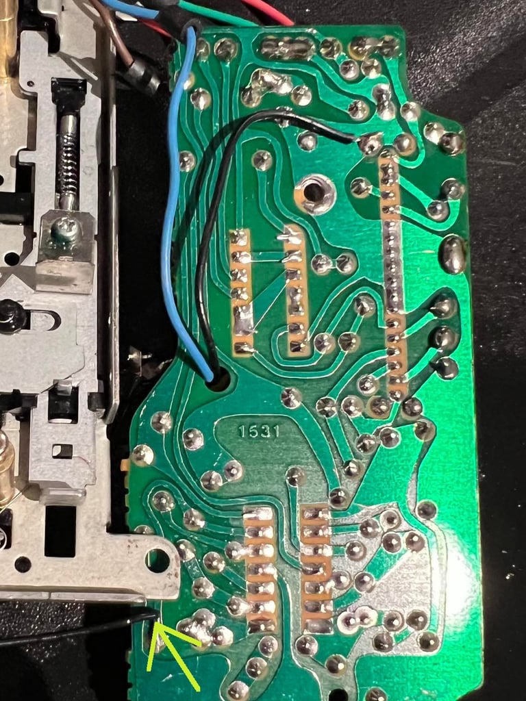
This PCB have a small mark saying "1531" on the back of the PCB. I wonder if this is a PCB that Commodore used both for their 1530 and 1531 datasettes? As far as I know the 1531 was used with the Commodore 16 and Plus/4 series.
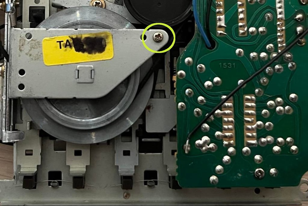
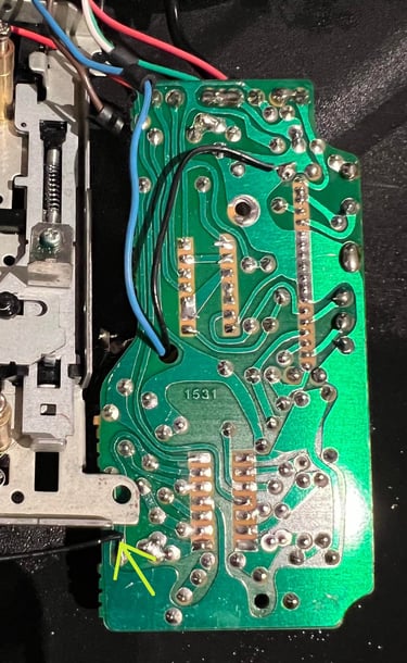
Backside of the PCB looks quite ok before cleaning. There are no signs of corrosion as far as I can see. Before cleaning the PCB I replace the electrolytic capacitors. To do this I first detach the PCB from the interior by removing the two screws connecting it. With the two screws out of the way I carefully lift the PCB to expose the little switch below. This switch is detached by removing the screw connecting it. See picture below - circle around the switch.
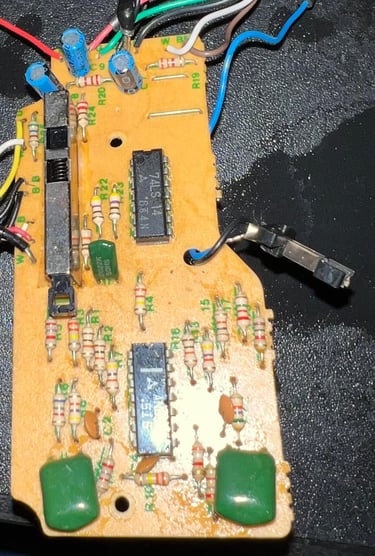
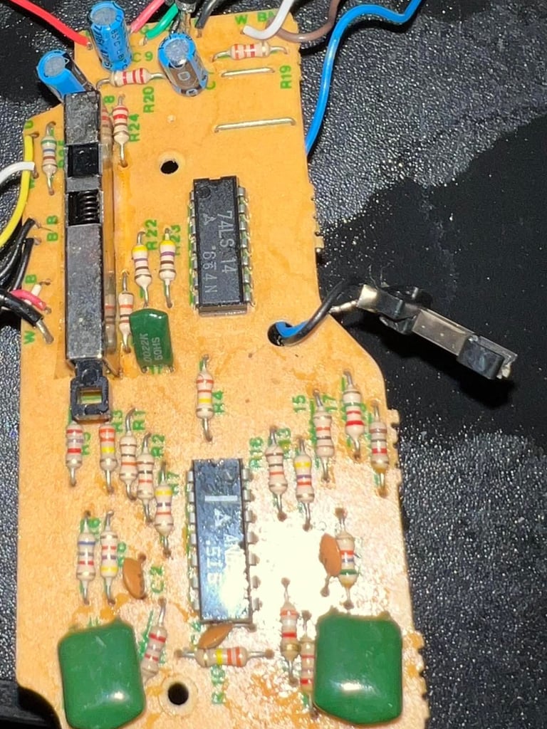
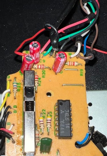
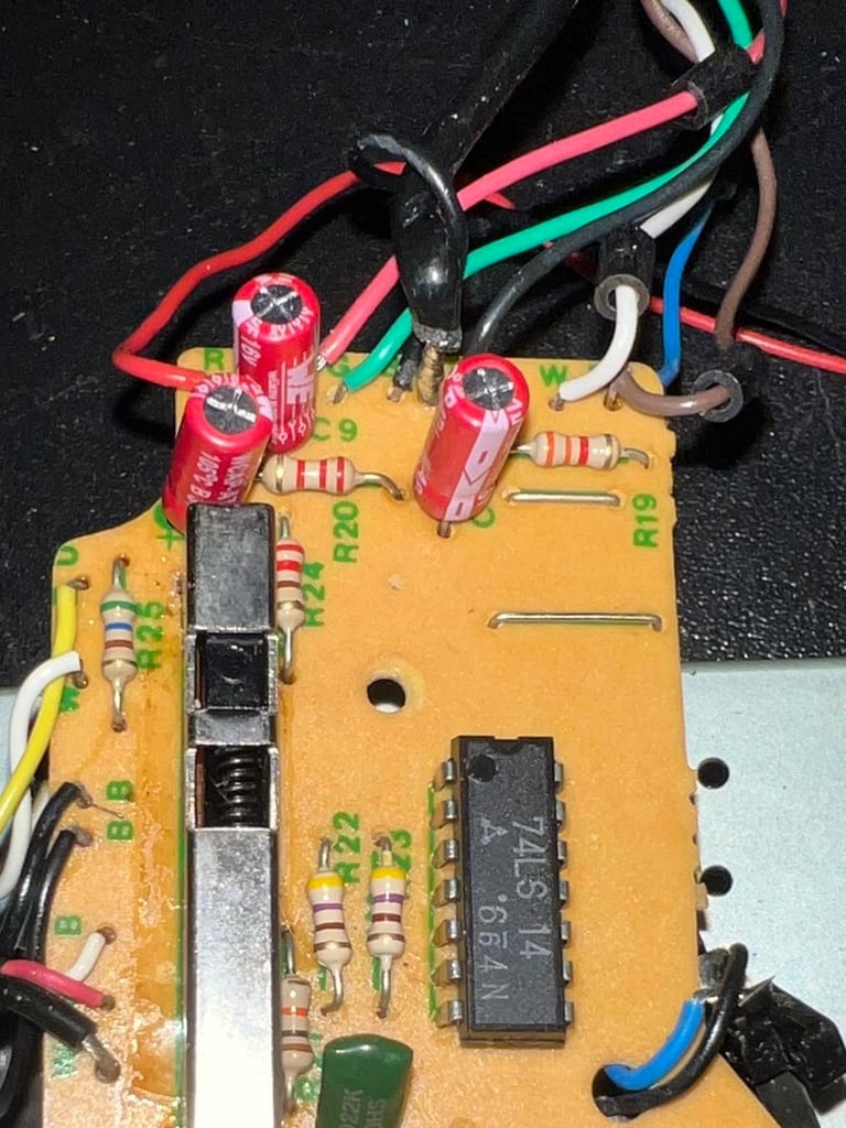
Frontside of the PCB is cleaned with isopropanol. The PCB looks ok - no leaking capacitors or damage. Nevertheless, the electrolytic capacitors are prone to dry out due to old age - so these are replaced with new quality capacitors. Also, there is a wire with a loose end soldered to the backside of the PCB. It looks to me that this is connected to one of the OPAMP stages. Could it be that someone have tried to adjust the R/W head with a oscilloscope previously?! Nice! Anyway, I will desolder this wire - it´s not useful under normal operation.
Below are pictures both of the front- and backside of the PCB. Note that the arrow points to the solder point for the open-ended wire which will be desoldered.
There are three electrolytic capacitors on this PCB: 3 x 47 uF [16V]. These are replaced with quality capacitors from Wurth Electronics.
Read/write head alignment
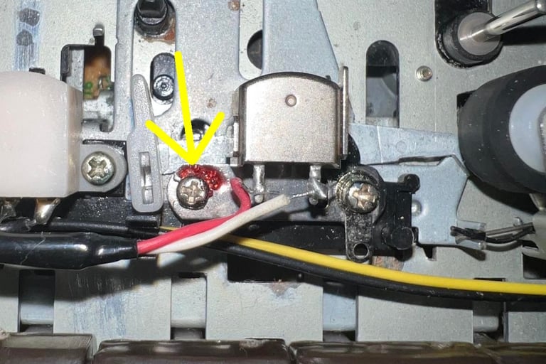
In addition to having new motor belt it is important to have the read/write (R/W) head align for optimal tape playback. The principle for adjusting the read/write head is simple; adjust the alignment screw until maximum signal strength is reached.
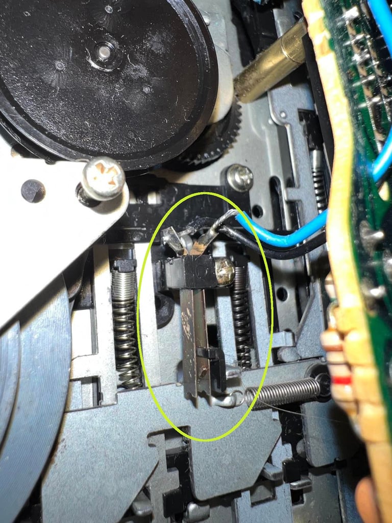
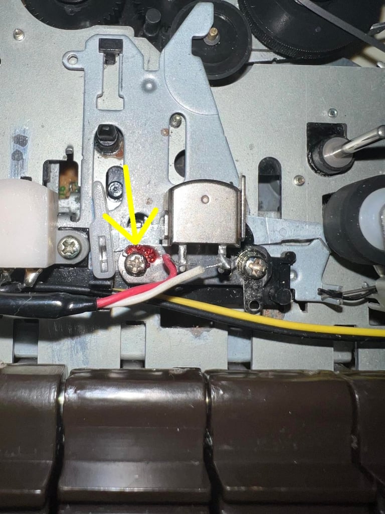
The alignment screw is located to the left of the R/W head. Note that there is a small blob of paint here on the screw. This is normal. It is used to "lock" the screw in position after alignment is complete. I will add some new paint (nail polish) after the alignment process is complete. In the picture below the arrow indicates the position of this alignment screw.
NOTE: When aligning the datasette it is best to do this when the chassis (top- and bottom cover) is assembled. This will make sure that the cassette tape is in the correct position when the alignment is done. On the 1530 C2N datasette there is a small hole just above the Commodore logo where you can reach the alignment screw.
To measure the signal strength from the R/W head it is smart to do this not directly on the head, but at the 2nd OPAMP stage in the datasette. In the datasette the signal is amplified four times in an OPAMP chain. Below is a picture of this OPAMP chain (credits: World of Jani).
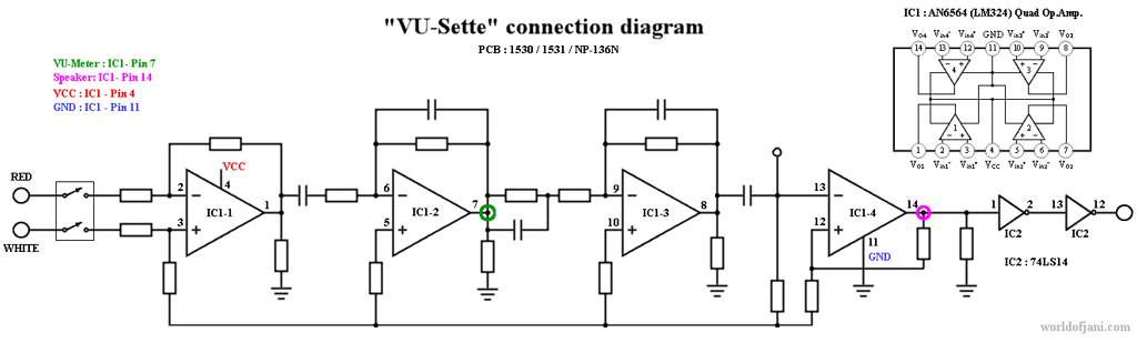

This signal from the R/W is input for the first OPAMP stage. The OPAMP (AN6564) chain will at the 3rd stage make the signal output saturate into a square signal. But at the 2nd stage the signal is still identical in its shape as at the input, but amplified. This makes it a good place to connect the oscilloscope and measure the amplitude. In the schematics above this is at pin # 7 (marked with a green circle).
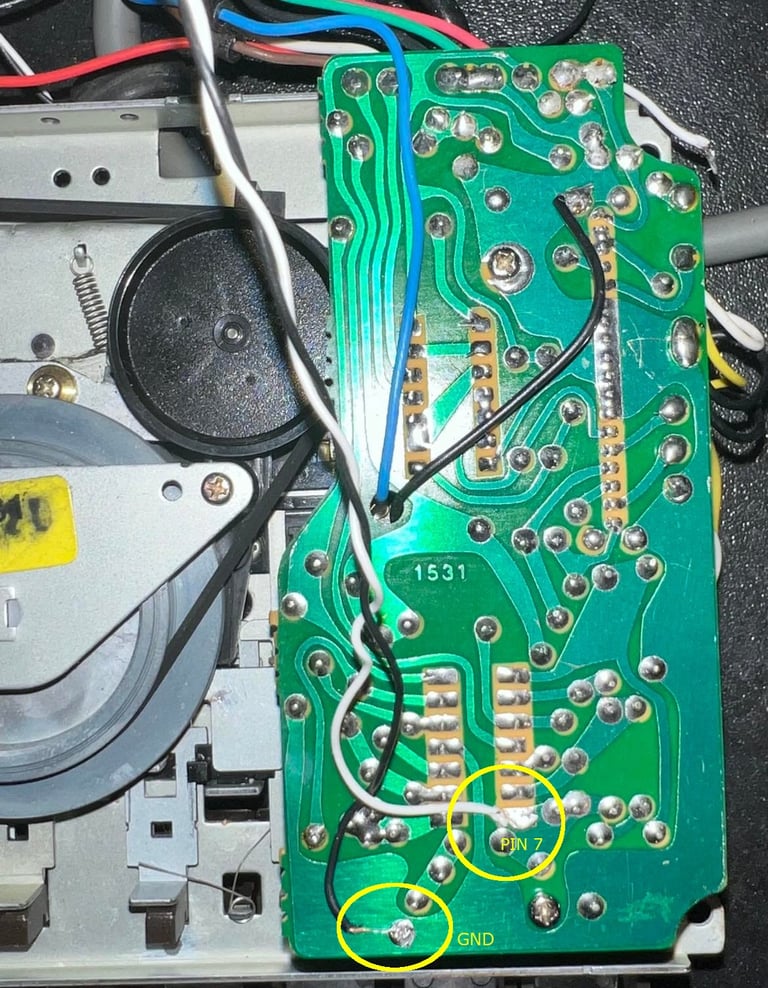
Two wires are soldered (temporarily) to the PCB. One wire to ground (GND) and one from at pin #7 from the OPAMP. Picture below - see circles.

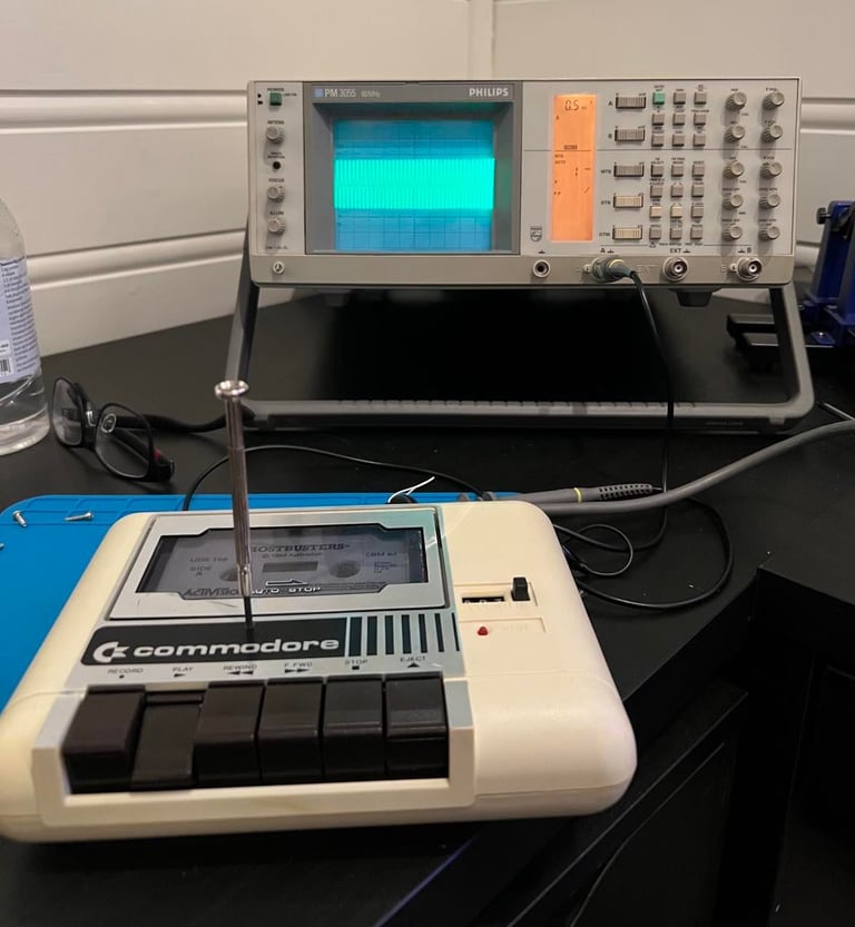
With the oscilloscope connected, and an original C64 tape running, I adjust the azimuth screw until I reach the maximum amplitude. Below is a picture from the adjustment process.

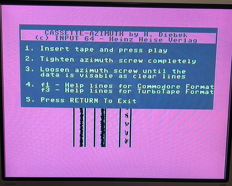
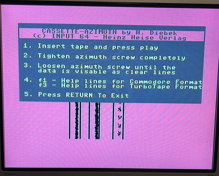
After the adjustment is done using the oscilloscope, I verify the adjustment using the cassette-azimuth software on the Commodore 64. The datasette should show three vertical lines - with low scattering - which is does now (see picture). You can argue that you can skip the oscilloscope step, which is true, but mye experience is that it´s both much faster and more accurate to use the oscilloscope first and then verify with the cassette-azimuth software.
Testing
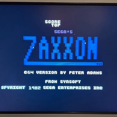
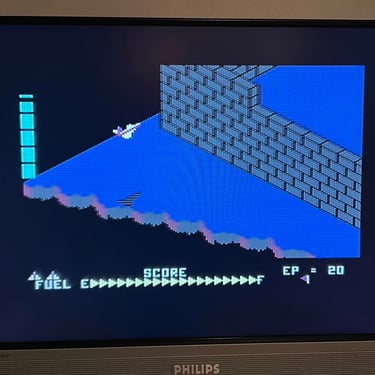
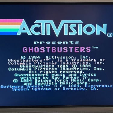
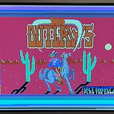
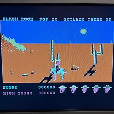
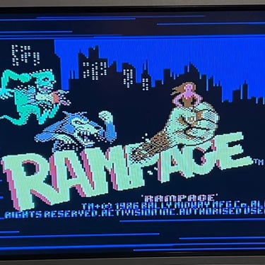
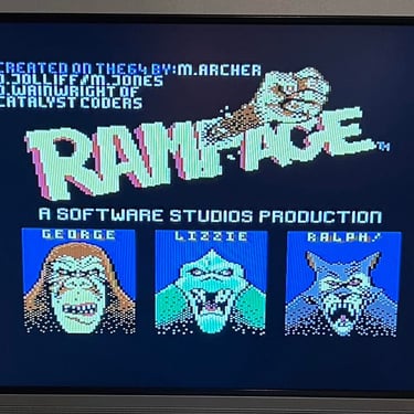
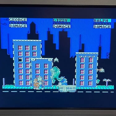
Ok! It´s time to test the datasette to see if it works as it should. This is done by choosing four original games at random. I use original old games for testing. These are professionally recorded - and since they are old they are often marginal which makes the test harder. See below for the chosen games.
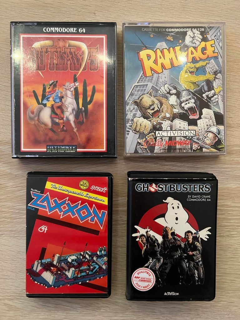
All games load without any problem at all - below are some pictures from the testing.

Final result
"A picture worth a thousand words"
Below is a collection of the final result from the refurbishment of this datasette. Hope you like it! Click to enlarge!
Banner picture credits: Evan-Amos