

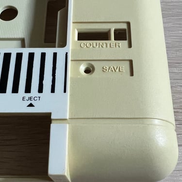
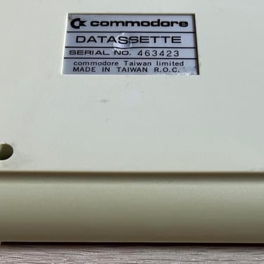
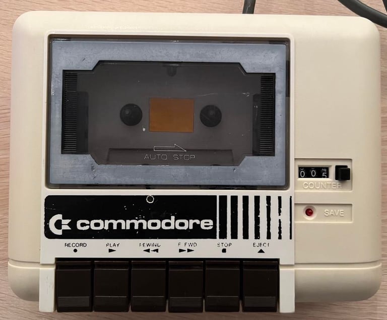
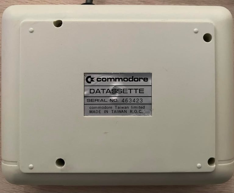
1530 (C2N)
Ser. No. 463423
Refurbishment plan
To refurbish this datasette the plan is to do this trough the following steps (some of these in parallell):
- Clean and remove stains from chassis
- Clean the interior mechanics
- Replace motor- and counter belts
- Check PCB for corrosion and replace old electrolytic capacitors
- Adjust head for optimal tape reading
- Verify datasette operation by testing
Chassis
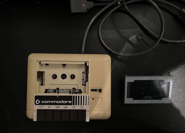
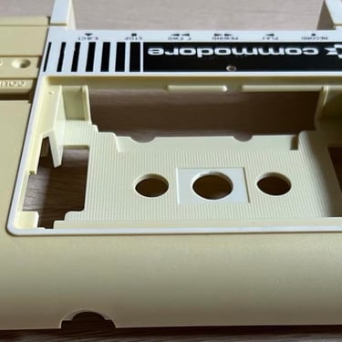
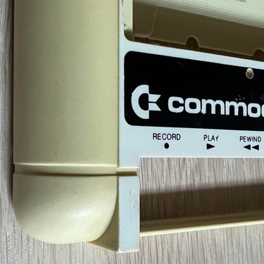
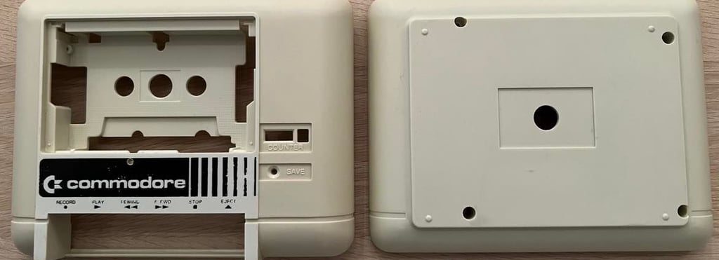
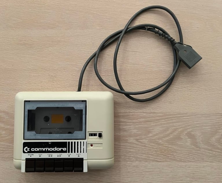
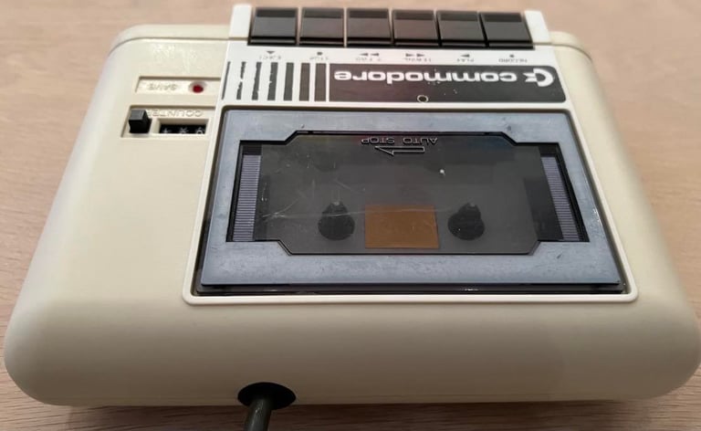
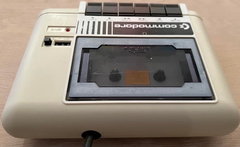
This is a datasette I started working on a while ago... Well, only cleaning it - but I think I cleaned it too much! The "metal" look on the Commodore area went away. Maybe it´s not as "nice" as an original with the metal, but this one is now unique and we´ll make sure it´s working fine! Below is a picture of the datasette before this refurbish begins...
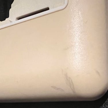
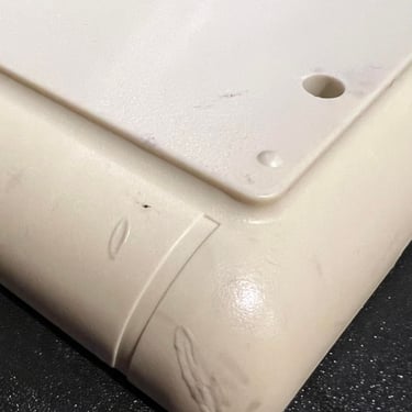
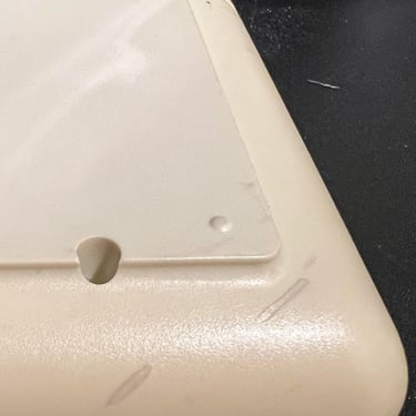
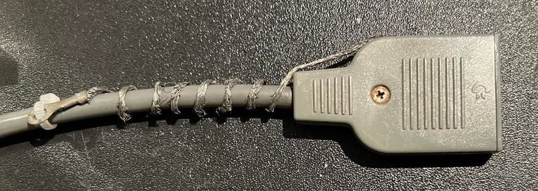
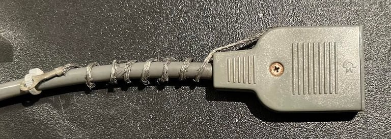
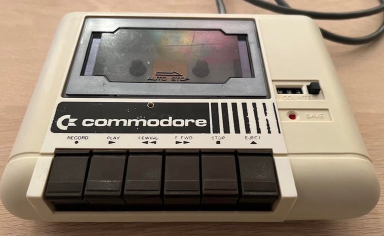
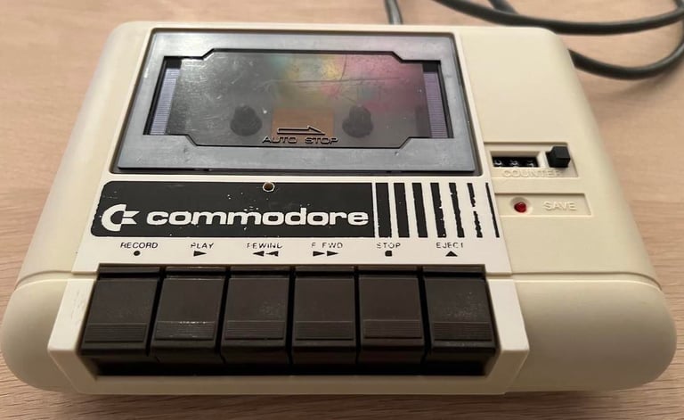
The plastic is a bit yellowed, and there are some quite severe markings from the cable which probably have been wrapped around. See pictures below.
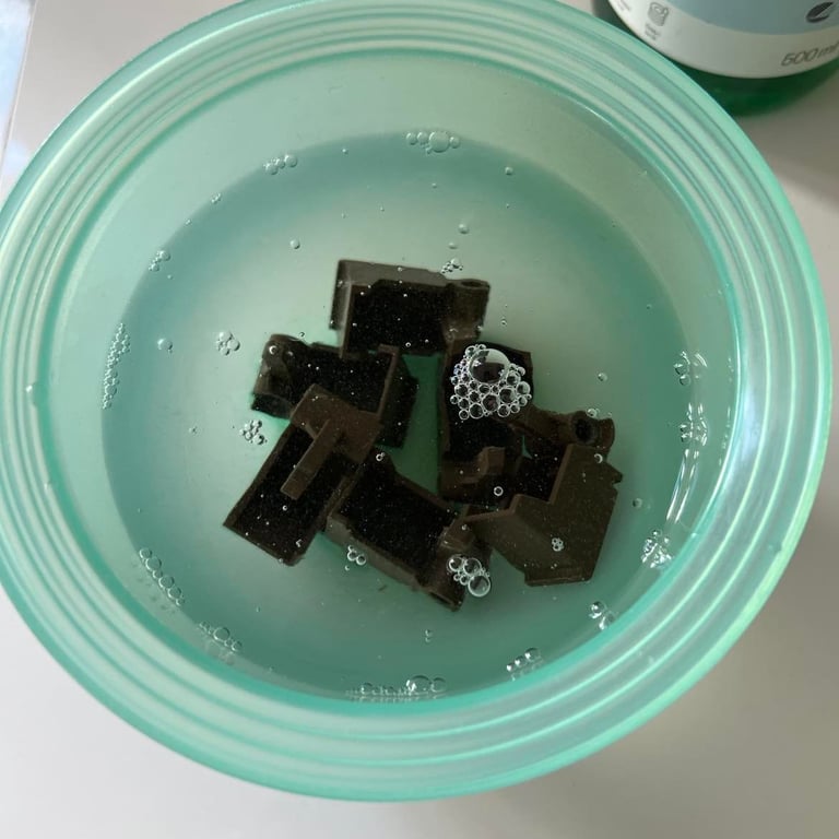
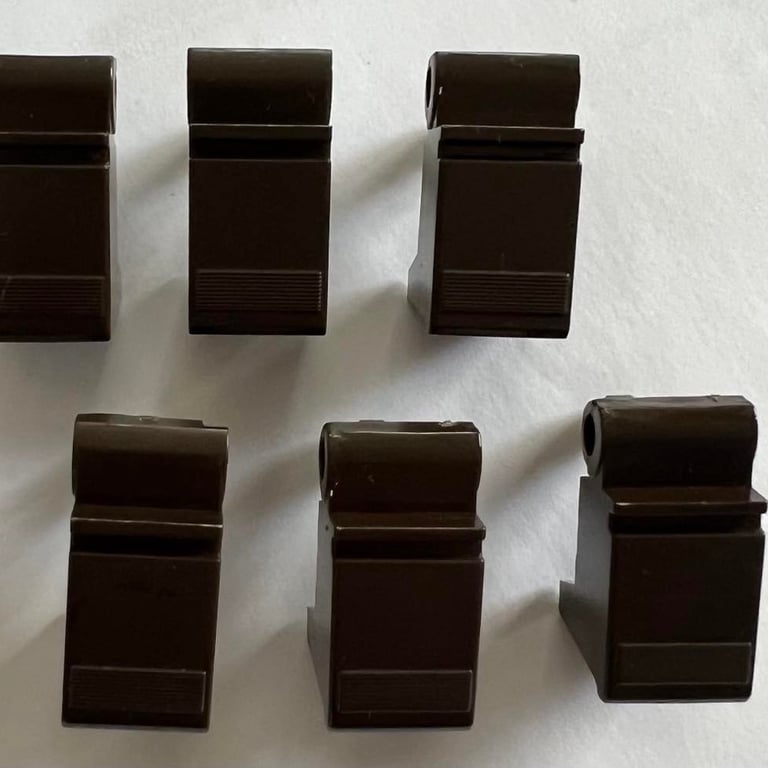
All the keys (FF/REW etc.) are disassembled from the chassis. This is done by removing the small latch on the right hand side of the keys, and then carefully remove the axel. Notice that it´s important to be very careful when removing the keys from the interior. There are three small Y-shaped springs on the back of the interior pushing the keys. The keys are washed with luke warm soap water and dried.
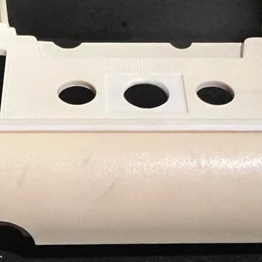
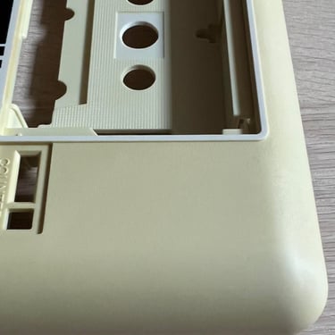
To remove the markings from the wrapped-around cable (which are quite severe in some places) I use a method of wet sanding. The way I do this is to first soak P240/P180 sanding paper with water, and then use this to gently sand the chassis. The focus area for the sanding is of course where the markings are, but I also try to sand other parts to make it look more natural. After the first sanding is done I sand another round, but this time with P1000 sanding paper. This paper is very good to remove most of the streaks that come from sanding. It´s not perfect, but I think it´s way better than the previous marks. Pictures below show the result after two rounds of sanding.
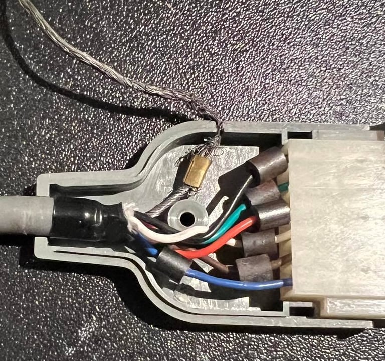
Cable looks to be ok - without any damage. The connector is opened to check that everything is ok also inside, and the ground wire is wrapped around the cable to make sure it doesn´t shortcut the userport. Note that this ground cable is not used in the Commodore 64 (it´s a legacy cable from older computer systems).

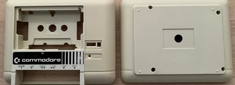
The datasette is quite yellow so I retrobright the chassis using 12 % hydrogenperoxide cream and UV light for about 8 hours. The chassis is now much whiter than before, but the logo is a bit more damaged. But not a big deal I think. See pictures below.
Interior mechanics
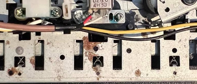
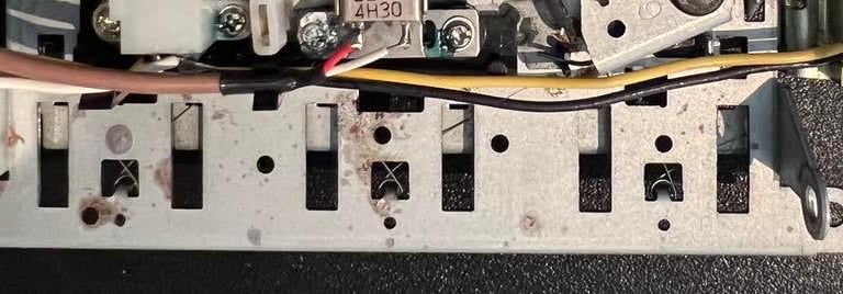
The interior is cleaned with a combination of compressed air, isopropanol, vinegar and some soap water. Vinegar is very efficient to use to remove rust stains. It´s quite common to see rust below the key area. Below you can see how efficient the vinegar is to remove these rust areas.
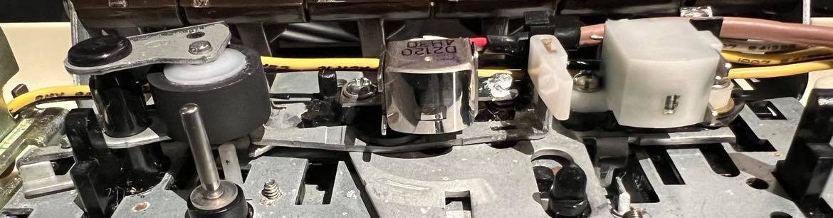
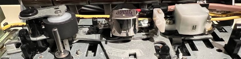
When cleaning the interior there are four areas that needs special attention. If these areas are not cleaned sufficient the operation of the datasette may not be optional. These four areas are (see picture below for the position of these):
The erase head
The read / write head (R/W)
The capstan
The pinch roller
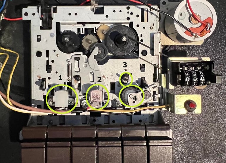
The erase head (1) and the R/W head (2) is cleaned with isopropanol on a Q-tip. The capstan (3) and the pinch roller (4) is also first cleaned with isopropanol. But for these two I also use a trick: I connect the datasette to the C64. While it´s connected I press keys such as PLAY/REW/FF to get the capstan and pinch roller to rotate. With isopropanol first and then some mild soap water last I carefully clean these while rotating. I´ve made some short videos previously on how I clean the pinch roller and the capstan if you are interested.
Below is a picture of the erase- and R/W heads, the capstan and the pinch roller after cleaning. Click to enlarge.
Replacing the belts
There are two belts in a Commodore datasette; the counter- and drive belt. The former is not strictly necessary to replace, but the latter is. With a worn out drive belt the datasette will have problem reading the tapes properly causing the well known "Load error?" amongst other problems.
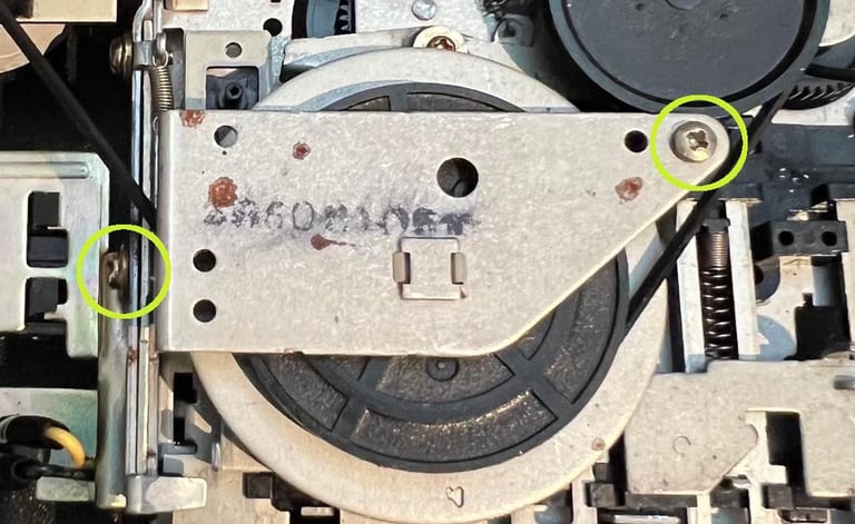
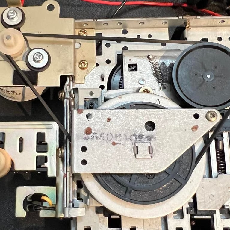
To replace the counter belt is easy. Just lift the small "handle" over the belt and remove the belt from the gears. But to replace the drive belt some more care is required. First the two screws marked with circles in the left picture below is removed. Then gently lift the metal shield just enough to get the belt out as the picture to the right. If you lift too much you risk that the little spring connected to the metal shield will pop off. Not a big problem, but could be quite time consuming to get back in...
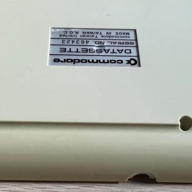
The belts are really worn out. I don´t think the pictures actually describes how loose they are - but believe me - they are barely holding the position in the gears. So new ones are without any doubt required for this datasette. I get my datasette belts from dataserve-retro.co.uk. NOTE: when ordering new belts for datasette, make sure you order the right version! This is the "Made in Taiwan" datasette, so that´s the version we will use.
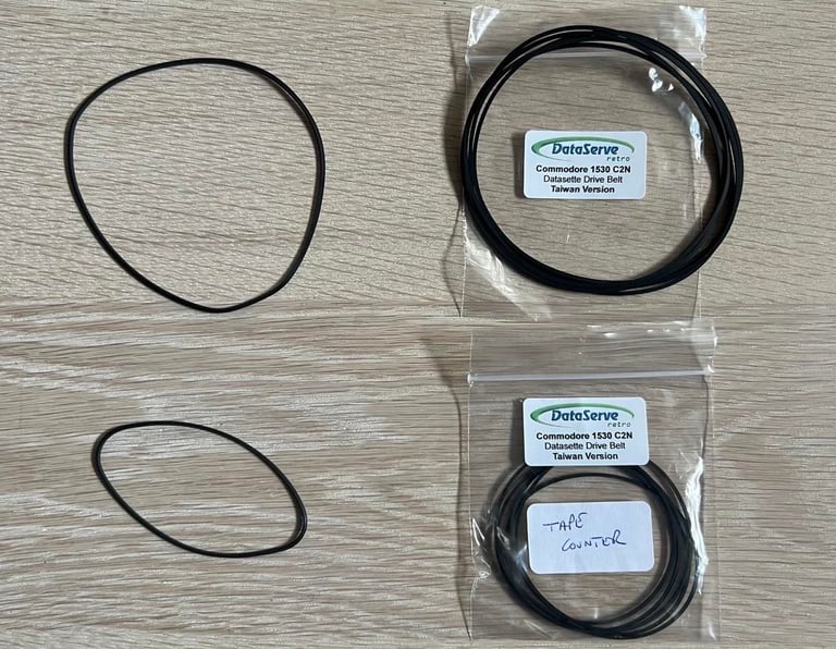
Below are the pictures of the new drive- and counter belt in place. Click to enlarge.

PCB and electrolytic capacitors
Both sides of the PCB is cleaned with isopropanol. The PCB looks very nice even before the cleaning. Three electrolytic capacitors are replaced:
2 x 47uF [16V]
1 x 0.47uF [50V]
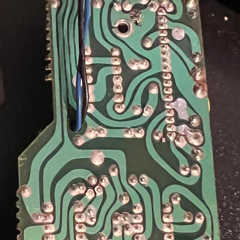
Note that the original 2 x 47uF capacitors were originally 10V, but it´s ok to use a slightly higher voltage. See pictures below for the back and front of the PCB with the new capacitors installed.
Read/write head alignment
In order for the datasette to work as expected it´s crucial that the read/write (R/W) head is aligned to optimal reading. The aligning is done by adjusting the left hand side of the R/W head - and when the optimal position is found the R/W is locked by adding some glue/nail polish to the screw.
Now, I notice that this datasette probably have been adjusted after it was produced. Why? Because I see that there are some paint (?) marks on this alignment screw which I belive is not from production. See picture below.

In order to obtain the optimal R/W position I follow these steps (with the datasette completely assembled!):
Tighten the screw completely - this is now the starting point for the adjustment process
Connect the oscilloscope to the output of the 2nd OP-AMP
Start the playback of a working original C64 tape
While watching the oscilloscope turn the screw until maximum signal amplitude is reached
Disconnect the oscilloscope
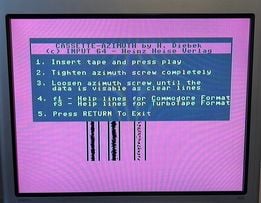
Start the playback of the same original C64 tape again while C64 cassette azimuth software is running
Verify that the cassette azimuth software display three solid lines - if not go back to step 1
Lock the screw with a drop of nail polish
I think that this method give the best result. You can basically just use the azimuth software while turning the screw, but my experience is that it´s better to use the oscilloscope when adjusting and use the software to confirm "yes, this is correct position".
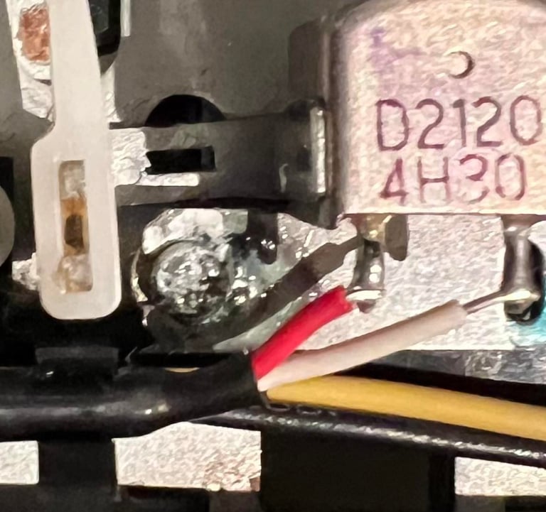
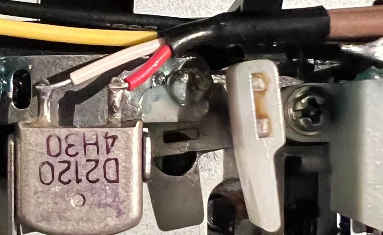
First, I need to solder two wires which will be used with the oscilloscope. These two wires will be soldered on the output of the 2nd OP-AMP and ground. This datasette has two separate OP-AMP chips (instead of one OP-AMP chip which is quite common in datasettes). World of Jani have a very good article on how to make a VU-datasette. And in this article there is also some very nice schematics of the datasette which I use to find the correct pin to solder the two wires. This article does not have the exact same PCB version as this datasette, but it´s very similar. Below is the schematics I use to find the 2nd OP-AMP stage (schematics taken from World of Jani).

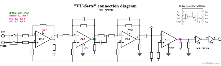
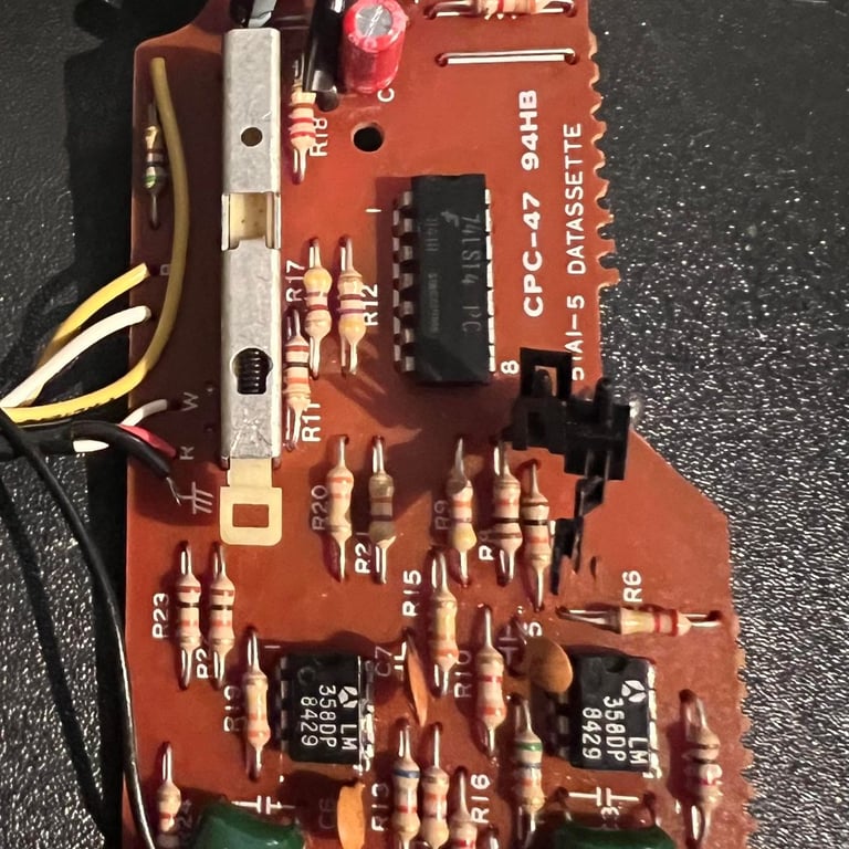
Even if this schematics is for PCB version NP-090B (versus this datasette which PCB is marked with "CPC-47 94HB") they are probably identical. As seen from the pictures in the chapter "PCB and electrolytic capacitors" above we have also two LM358 OP-AMPs. So I solder in the two wires as seen in the picture below (click to enlarge).
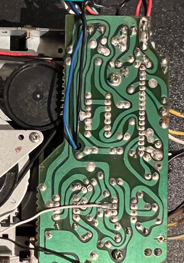
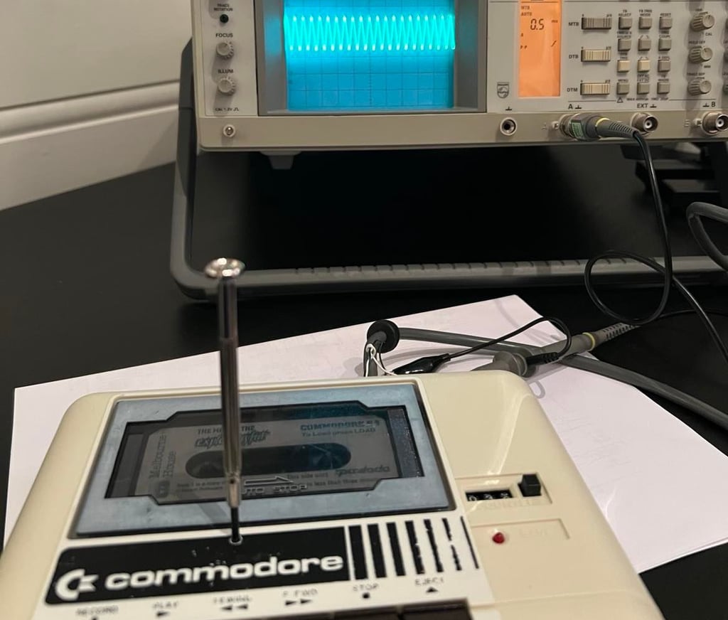
With the two wires sticking out of the back of the datasette I start the process of "unscrewing" the screw to find the optimal position of the datasette. As mentioned previously it´s important that the datasette is completely assembled (with screws, lid and everything). This way you know that the R/W head is adjusted to the exact position when the tape is placed in the lid and the chassis tightened. Below is a picture from the process where the R/W head is adjusted while simultaneously watching the oscilloscope.

When I´m satisfied with the maximum signal amplitude I disconnect the oscilloscope and run the cassette azimuth software on the C64. This should now display three solid lines during playback. And it does! See picture below.
Short note: I say "solid lines". That means that the three lines are not scattered around. They are not solid literally, but they are confined within the vertical lines.

To make sure the screw stays in position I add a drop of nail polish (thanks to my daughter:-))

Testing
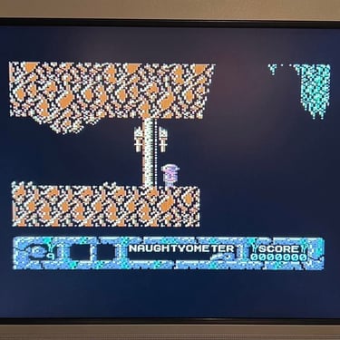
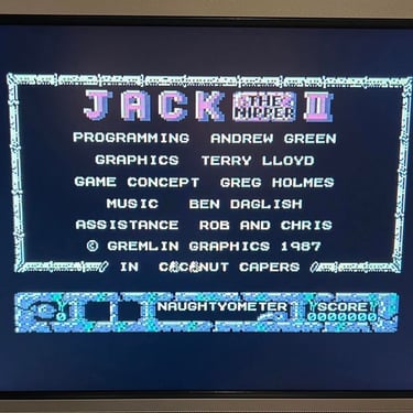
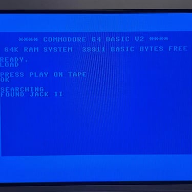
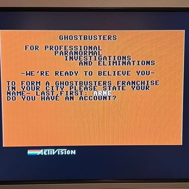
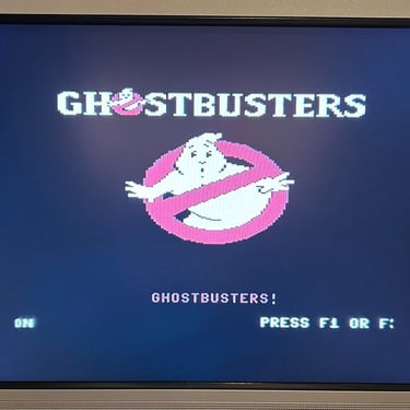
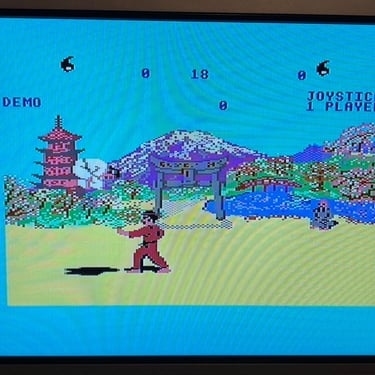
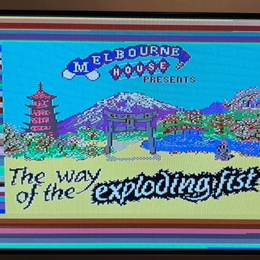
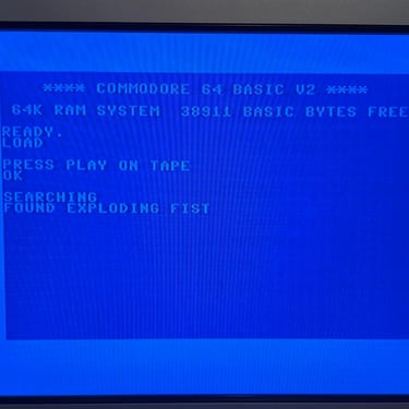
Best part of the refurbishment! Test the datasette and PLAY some games! I select three random original games:
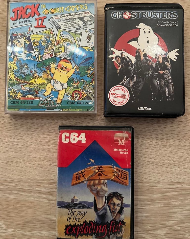

All games works perfectly, and they load at first attempt. Below are some pictures from the testing. I conclude that this datasette is now working as expected!
"A picture worth a thousand words"
Below is a collection of the final result from the refurbishment of this datasette.Hope you like it! Click to enlarge!
Final result


Banner picture credits: Evan-Amos