

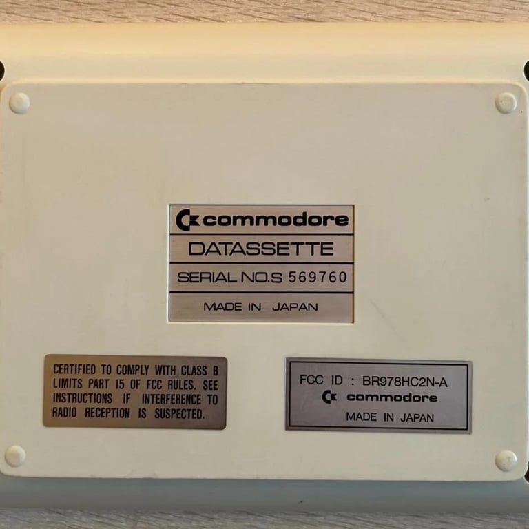
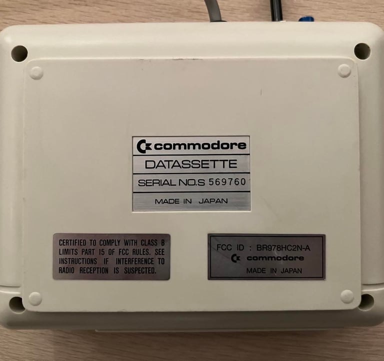
1530 (C2N)
Ser. No. 569760
Refurbishment plan
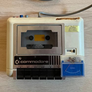
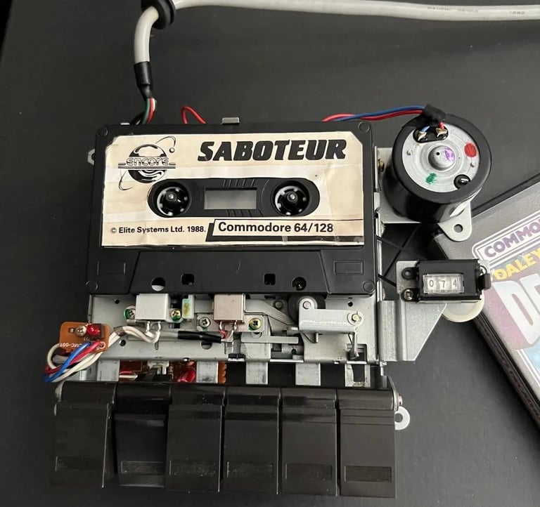
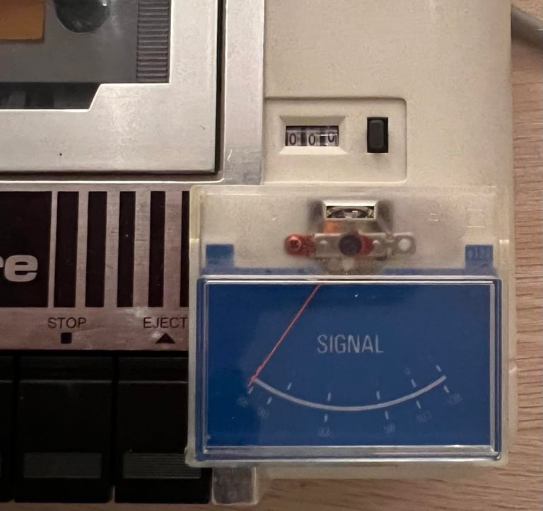
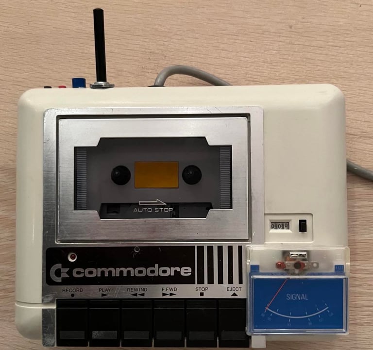
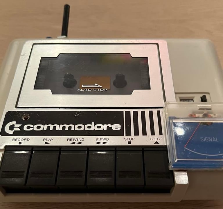
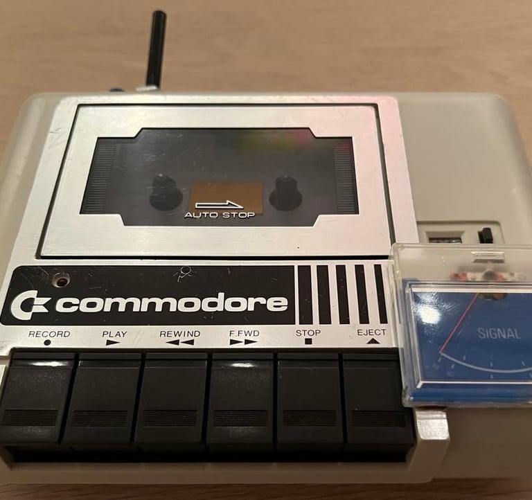
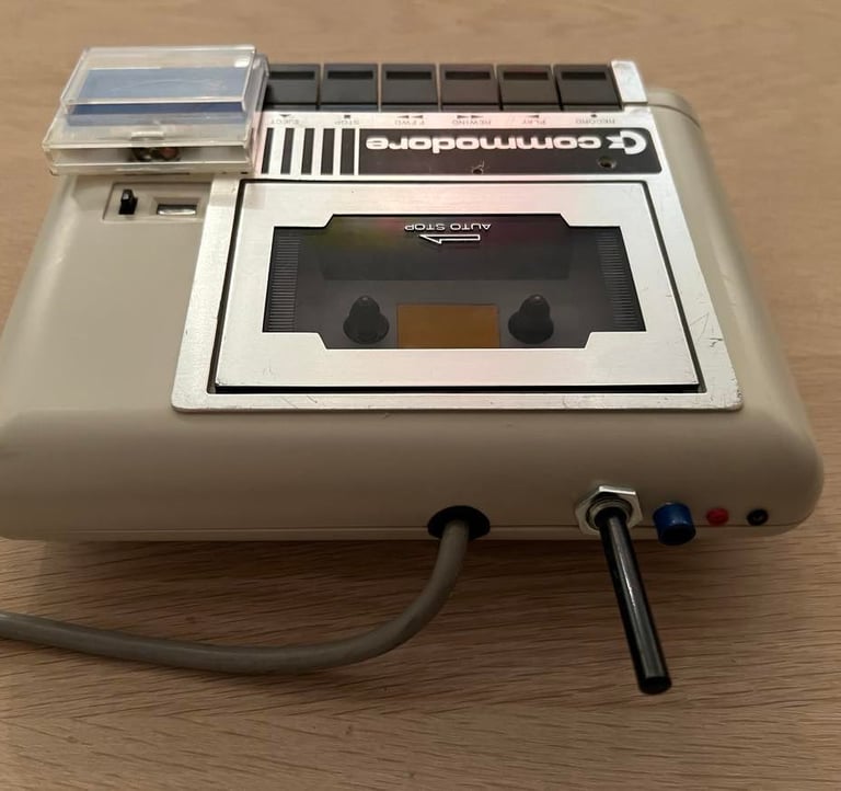
This is a customized datasette. Previous owner has installed a signal/VU meter - probably to check signal strength during playback and recording.
To refurbish this datasette the plan is to do this trough the following steps:
- Clean and remove stains from chassis
- Clean the interior mechanics
- Replace motor- and counter belts
- Check PCB for corrosion and replace old electrolytic capacitors
- Adjust head for optimal tape reading
- Find out what to do with VU-meter; keep/repair/remove?
- Verify datasette operation by testing
Chassis
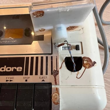
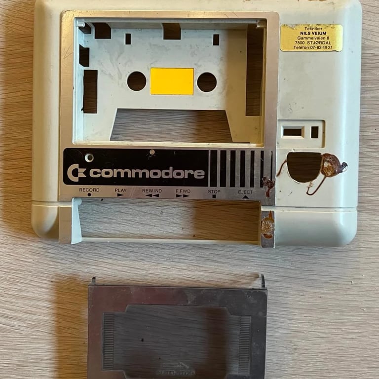
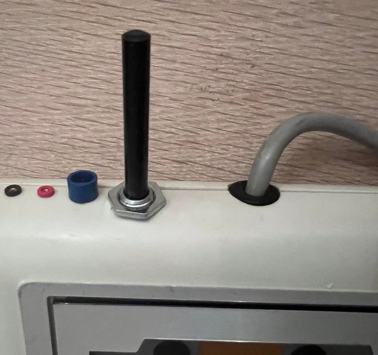
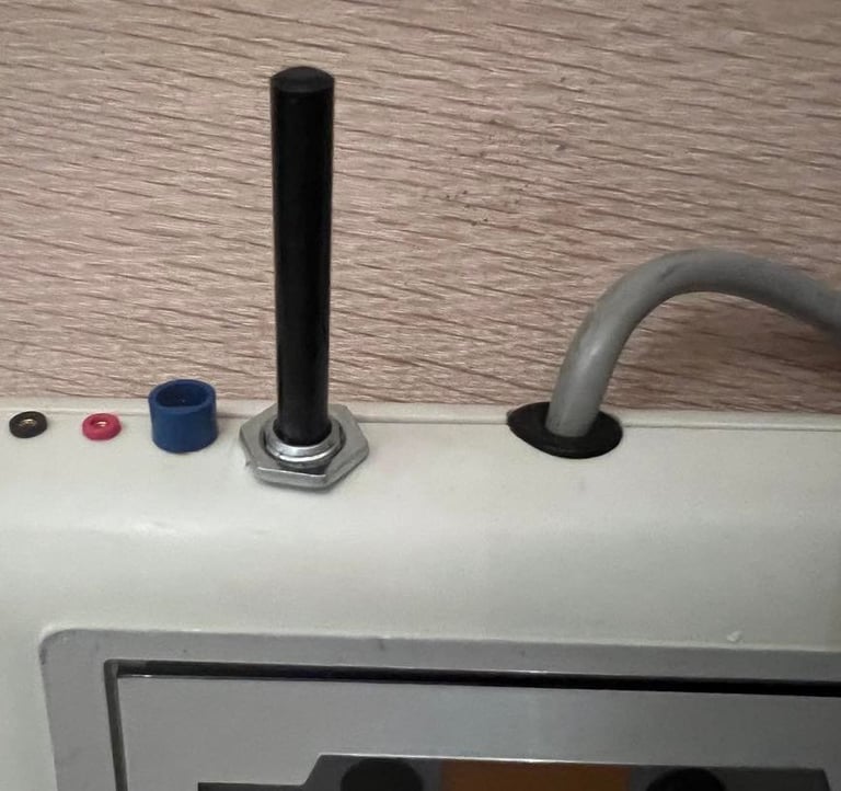
Oh oh oh... This datasette doesn´t look too good at the moment. It´s very dirty, has some strange glue (?) at different places and have a loose signal/VU-meter. The VU meter is quite interesting! I´ve never seen this before on a datasette - wonder if it even works. In addition there are four connectors at the back of the datasette: two larger and two small ones. No idea what they are used for?
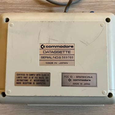
Nevertheless, let´s disassemble this and give it a good clean! The four screws at the bottom are removed. This is the "made in Japan" version of the datasette, and in this version the interior mechanics is fastened with additional four more screws to the top cover.
In order to get all the plastic parts disassembled I need to solder off the VU-meter and the connections to the four contacts in the rear of the datasette. The tape lid is also gently removed from the top cover.

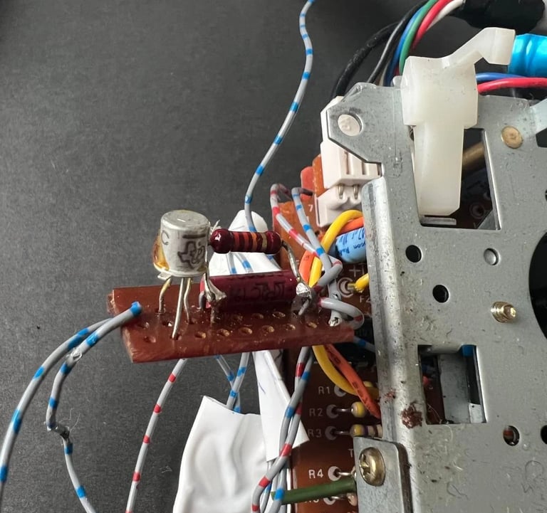
I notice that there is installed a 470uF capacitor (which is only connected to ground - the other end is disconnected). Also there is a small prototyping board with a transistor and some resistors attached. Not quite sure what this was used for - but my guess is that´s it´s used for amplifying the signal from the read/write so that it can used with some (very small) loudspeaker and/or to the VU meter.

The motor belt is completely worn out - it´s about to fall out any minute.
With all the plastic parts disassembled the cleaning process commence. First, all parts are gently cleaned with luke warm water and dishwater soap - and a painting brush. I use a painting brush both to be careful not to scratch the metal foil and the stickers. Note: often I remove the stickers at the back, but this time I try to leave them on. I think I can manage to clean the bottom cover without removing the stickers.
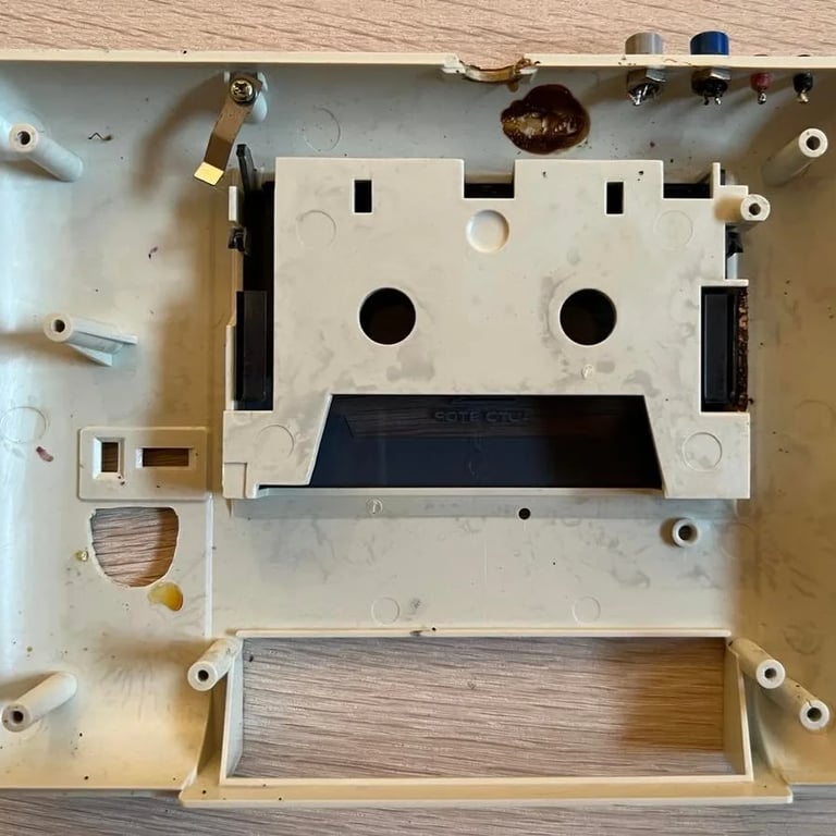
Most of the grease is removed with the dishwasher soap. And some of the glue residue from the sticker at the top cover is removed with isopropanol. But... the large glue-like marks where the VU meter was positioned and at the back will not come off easy. I start by carefully spray some grill/oven cleaner just on these areas. This can easily etch into materials such as metal foil/stickers etc. so be careful. It´s left overnight in hope that this will make it dissolve. It does to some extent. But, there is still plenty more.
So, the next is to try to sand it gently. I do this by first using P180 sanding paper on the specific areas. It´s REALLY hard to get it off. It´s some kind of glue which is really strong. But finally I manage to get it away. To get a nice finish I use P1000 wet sanding paper. This is tedious work, but it gives a quite nice finish to the plastic. Note; some glue residue is still left. But it will (hopefully) be beneath the VU-meter so it won´t be visible anyway.
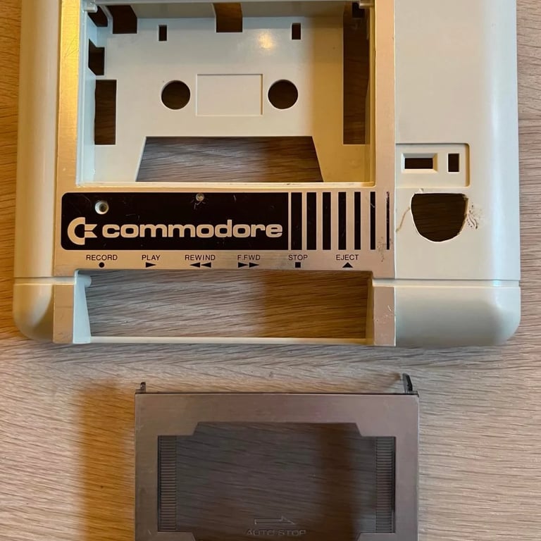
Final cleaning is done with baking soda and a cotton pad to remove the last stains. Here's the result (click to enlarge):
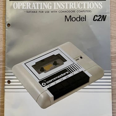
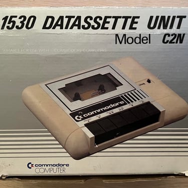
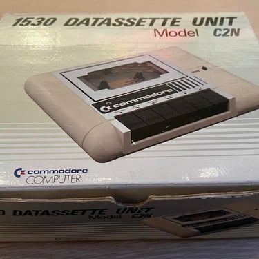
The original box and user manual are in a quite nice condition!
Interior mechanics
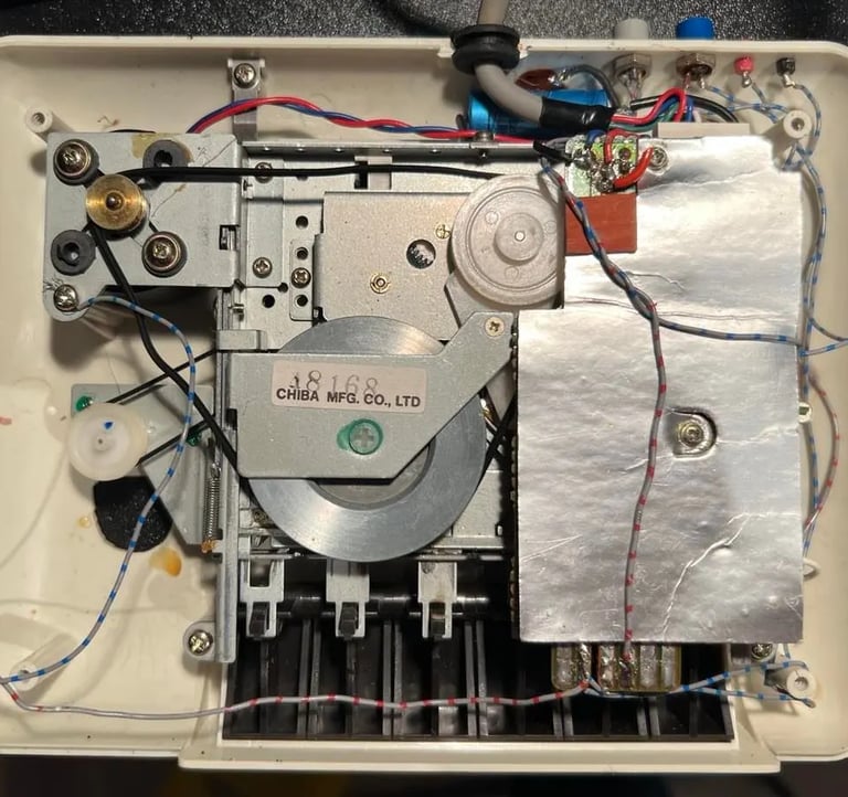
The interior of the datasette is cleaned thorougly with compressed air, isopropanol and luke warm water with mild dishwasher soap. I clean everything with the belts removed because isopropanol and rubber bands are not always the best combination - it's probably not a big problem, but I remove them anyway.
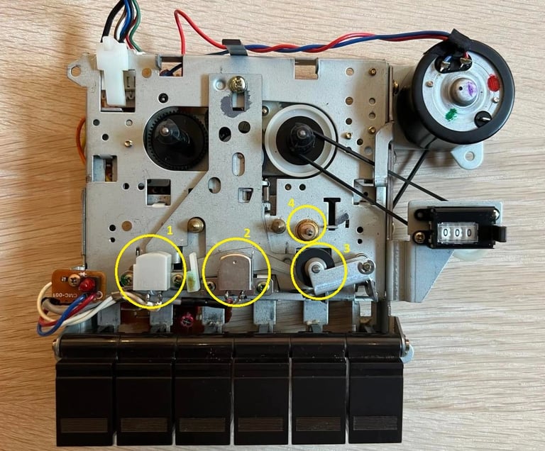
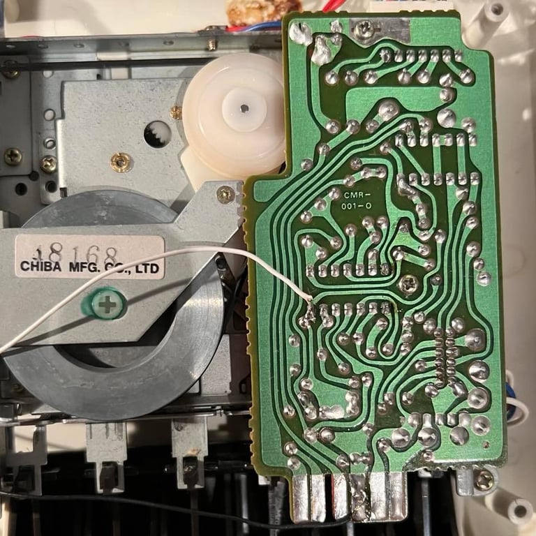
There are some special areas that are cleaned with care:
- The erase head (1)
- The read/write head (2)
- The pinch roller (3)
- The capstan (4)
In the picture below you can see the cleaned interior and also where these four areas are in the datasette.

To give a good clean to the rotating parts (e.g. pinch roller, capstan and gears) I connect the datasette my C64 when the belts are in place. I then push the PLAY/REW/FF buttons to activate all rotating parts, and then use a Q-tip with some mild dishwasher soap. Note: be careful if you do this because the Q-tip can get stuck!
A note about pinch roller: this was really dirty due to residue coming from all the old tapes. This is important to remove to that the pinch roller and the capstan can pull the tape properly. To get this old residue off I gently apply some sanding paper (P240) on the pinch roller rubber. Please note that I don't "sand" the rubber I just use the paper to loosen the dirt. Afterwards the rubber is cleaned with a small amount of isopropanol and water with mild soap.
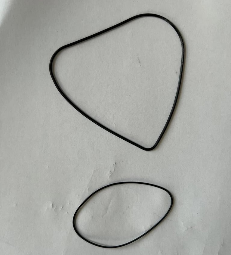
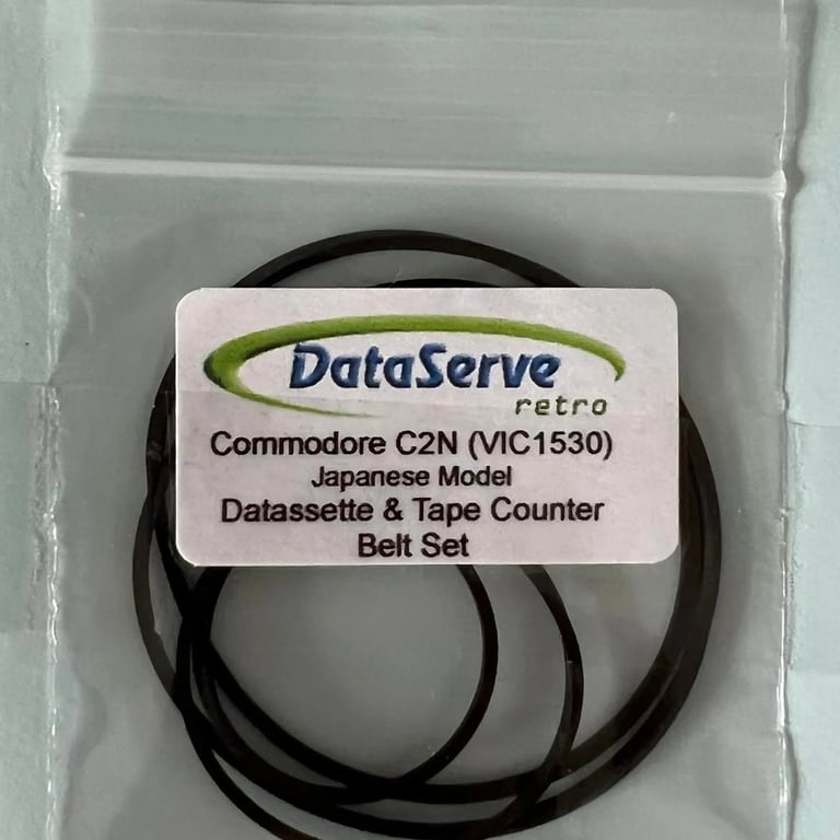
Replacing the belts
I´ve replaced quite a few datasette belts, but these belts are definitely among the top 5 worst I´ve ever seen. The motor belt is so worn out that it literally just fall out. New belts are being ordered from www.dataserve-retro.co.uk. Note: this datasette is the "Made in Japan" version - which is important to know when ordering new belts to make sure you get the right ones.
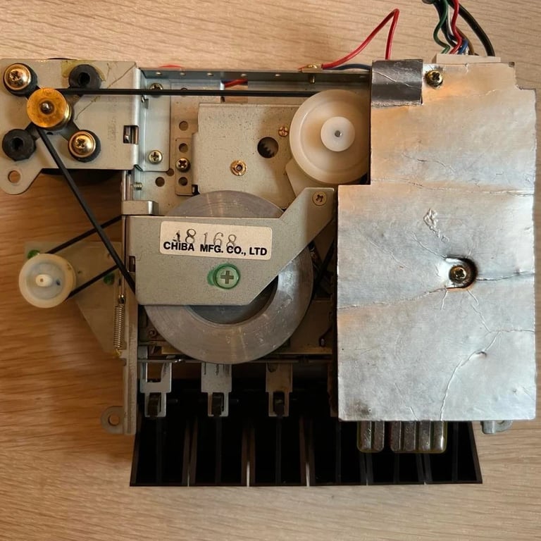
Compared to the "made in Taiwan" datasette this "made in Japan" version the replacing of the belts is very easy. You don't need to remove any screws to attach the new belt (you can remove the PCB for super easy access if you like). It's important to make sure that the belts are not twisted in any way. Below you see the picture of new belt for the motor (the new belt for the counter you can see in the chapter above).
With the new belts in place I do a quick test to see if the datasette "spins up" and loads a tape for the first time since probably 30 years... And it does! Nevertheless, this does not mean that the datasette doesn't need further alignment. But it does mean that the basic operation of the datasette seem ok! With new belts, new capacitors and all other strange stuff removed.

PCB and electrolytic capacitors
The PCB needs to be refurbished by:
- Removing all non-standard cables soldered onto the board
- Resolder some of the points (some of these have huge blobs - either from previous owner or from factory)
- Remove dirt and old flux
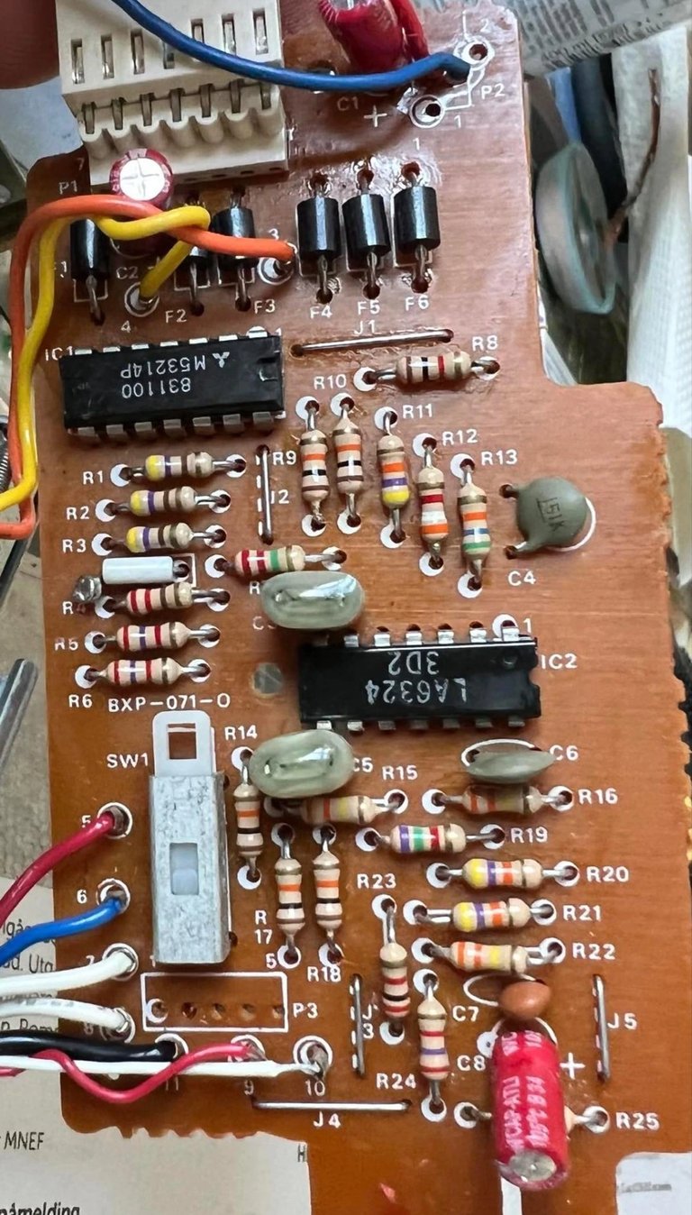
This PCB is the CMR-001 version (made in Japan). At zimmers.net the complete schematics and parts list can be found: https://www.zimmers.net/anonftp/pub/cbm/schematics/datassette/index.html
All cables are removed by soldering them off the PCB. Old solder is removed with solder wick. When, or if, the VU meter is installed back in some new wires must be soldered back in. But, until now everything non-standard is removed so that basic datasette operation can be verified.
I notice that a couple of the solder points are more "blobs" than points probably due to cold soldering, or just too much solder. Anyway, these solder blobs are removed with solder wick and the points are resoldered.
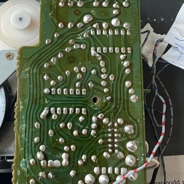
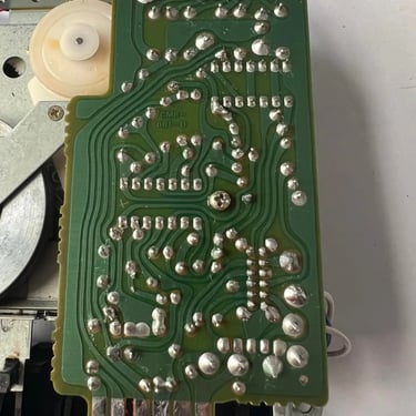
It´s quite impressive how dirty this PCB is. The picture can´t show this, but the PCB is full of some sticky stuff which I assume is old flux residue. Both the front and the back of the PCB is cleaned with isopropanol and an old tooth brush. I use a combination of paper towel and a microfiber cloth to remove the isopropanol remains.
Below you will find pictures from the cleaning and desoldering process (click to see the whole picture). The leftmost picture shows the PCB in it´s pre-cleaning state. The middle- and rightmost picture shows the PCB after cleaning and de-/resoldering.
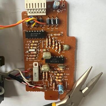
While desoldering I notice something: check the middle picture - and on the left side to the middle of the PCB there is a white ceramic resistor(?). But this component is not attached to anything? It´s just one leg soldered onto the PCB. I think this could be some remnant from the customized VU-meter installation, but I´m not sure... I need to leave it for now.
There are three electrolytic capacitors on this PCB: 0.47uF (25V) and 2 x 47uF (10V). These are replaced with new Wurth Electronics capacitors with a slightly higher voltage rating - but that makes no difference. The new capacitors are 0.47uF (50V) and 47uF (16V).
Read/write head alignment
When aligning the read/write (R/W) head on this datasette I choose to use a bit different method than before. Normally I measure the signal level directly on the R/W head. But this time I choose to measure on the second stage of the op-amp chain. This is done by connecting the probe to pin 14 and ground to pin 11. The schematics for this datasette is found at Zimmers (see online resources page). See picture below for the schematics and the point where I do the measure (pin 14 - marked with a small circle).
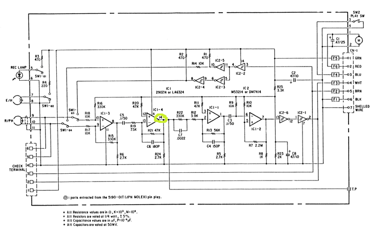
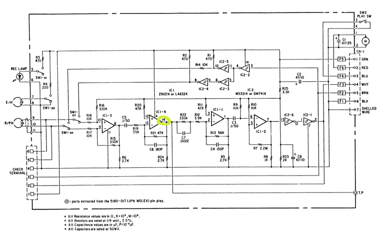
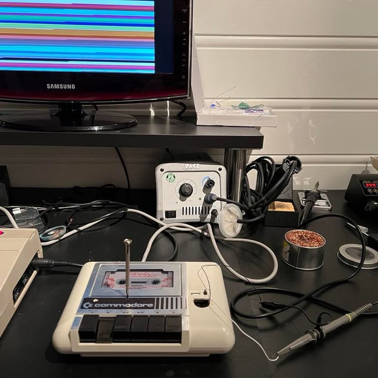
Below you find two pictures. The first show how I solder on (temporarily) two wires on pin 14 and ground, and these two wires are pulled out through the little hole in the front. The second one show the wires out of the small hole connected to the scope, and a small screwdriver to adjust the R/W head when the datasette is assembled.
To achieve optimal R/W alignment this is done in the following way:
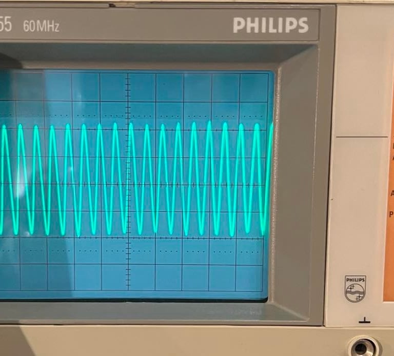
1) Adjust the R/W screw to find the optimal (highest) amplitude using the oscilloscope
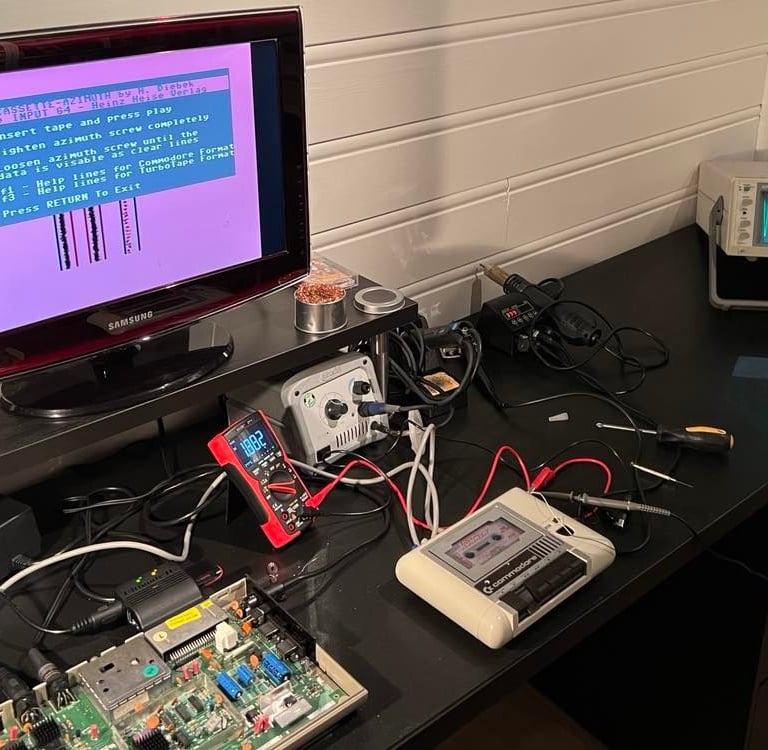
2) Confirm that this adjustment gives straight lines using the cassette-azimuth software
3) Lock the screw (with some nail polish or similar) to prevent the R/W head from moving during operation afterwards
I´ve found that combining 1) and 2) in the same operation often is the most efficient way. Below you find two pictures. The first one show the amplitude measured between pin 14 and ground (left picture), and the second one show the setup I used when calibrating the R/W head on this datasette to accomplish 1) and 2). Click pictures to enlarge.
VU-meter
I found this magnificent blog article from World of Jani. In this article there is a description on how to make use of a VU-meter by tapping the output signal from the datasette, amplify this and output this to a VU-meter. The schematics taken from the article is shown below:
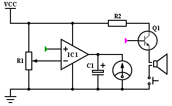
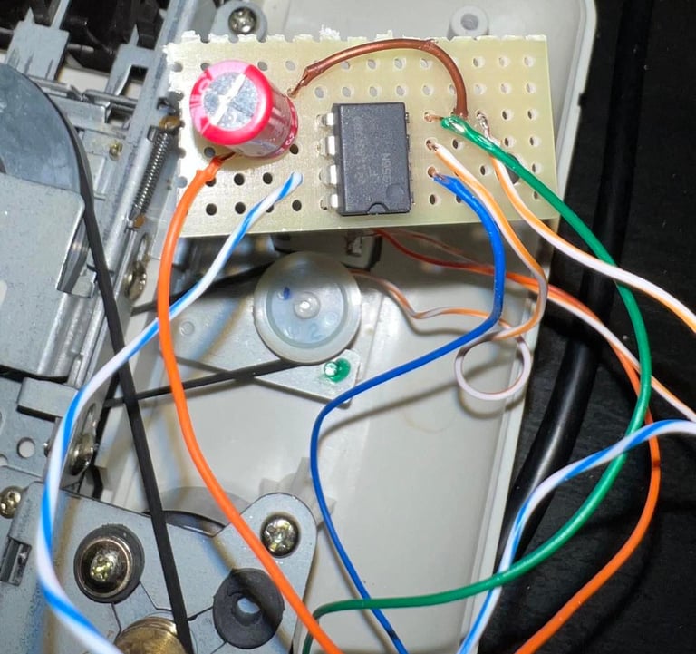
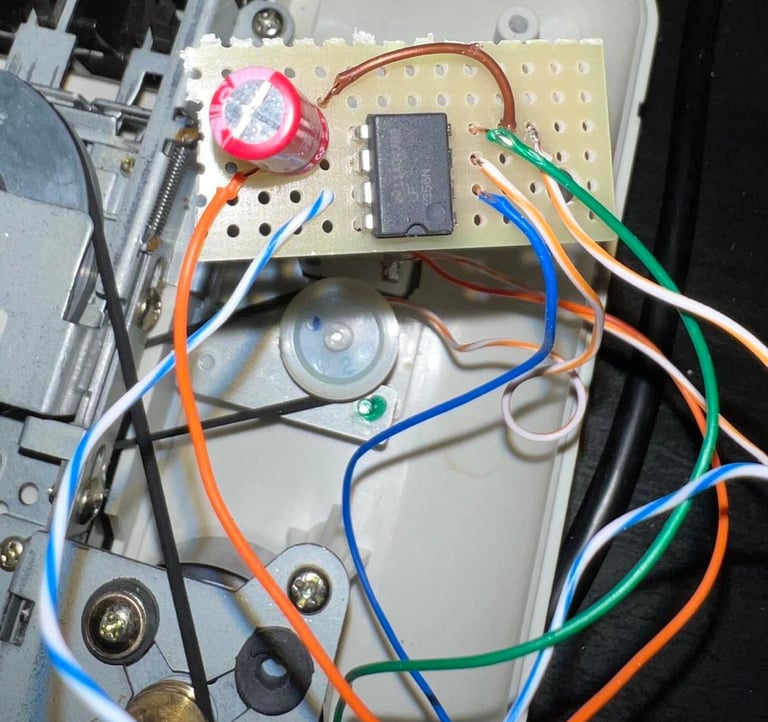
Based on this schematics I make a little "PCB" with a veroboard using the following components:
LM356 OP-AMP
330uF capacitor (C1)
10k Ohm variable resistor
The PCB is soldered to the +5V, GND and the (+) input on the OP-AMP is from pin 14 from the datasette OP-AMP. This is the same pin used when adjusting the R/W head with the oscilloscope.
It´s a bit tricky to adjust the VU-meter with the variable resistor sticking out of the back. The reason is that in order to find the maximum VU-peak you have to find the accurate position of the resistor by turing it carefully. But, nevertheless - this seems to work! I guess the VU-meter is more "fun to have" than "need to have":-)!

Testing
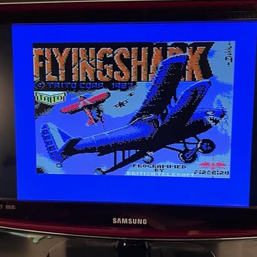
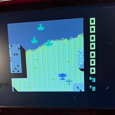
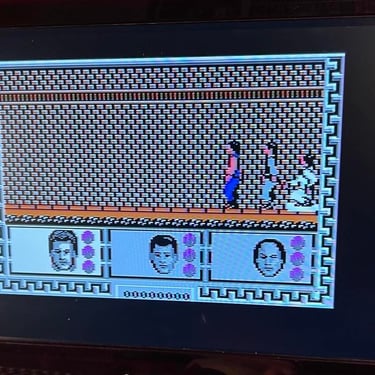
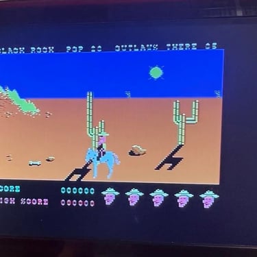
To test and verify the operation of the datasette I choose three games at random to load. See pictures below which ones I choose for this test.

As far as I can see the datasette loads these tapes without any issues. See pictures below for some samples. Also, I test the recording functionality (save) and that also works fine. So all in all - the test is ok and basic datasette operation is verified.


Final result
"A picture worth a thousand words"
Below is a collection of the final result from the refurbishment of this datasette.
Hope you like it! Click to enlarge!


"Are you keeping up with the Commodore? 'Cause the Commodore is keepin up with you!"
Espen Kraft from 5 Minutes Of Retro use this datasette when testing a 40 years old tape (never opened). Please check out the video below.

Banner picture credits: Evan-Amos