

1530 (C2N)
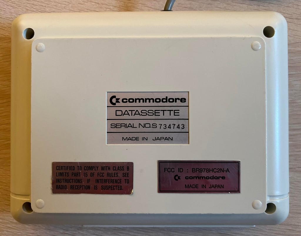
Ser. No. 734743
Starting point
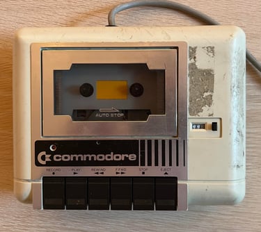
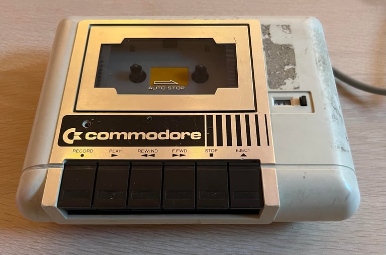
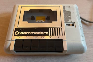
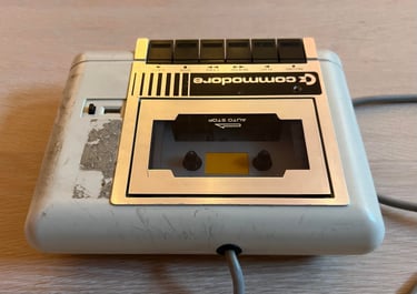
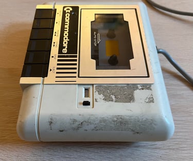
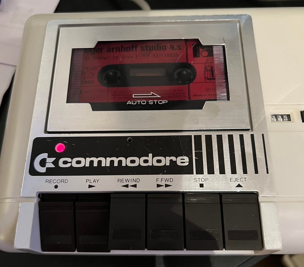
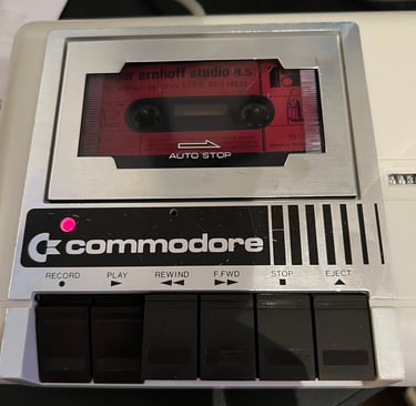
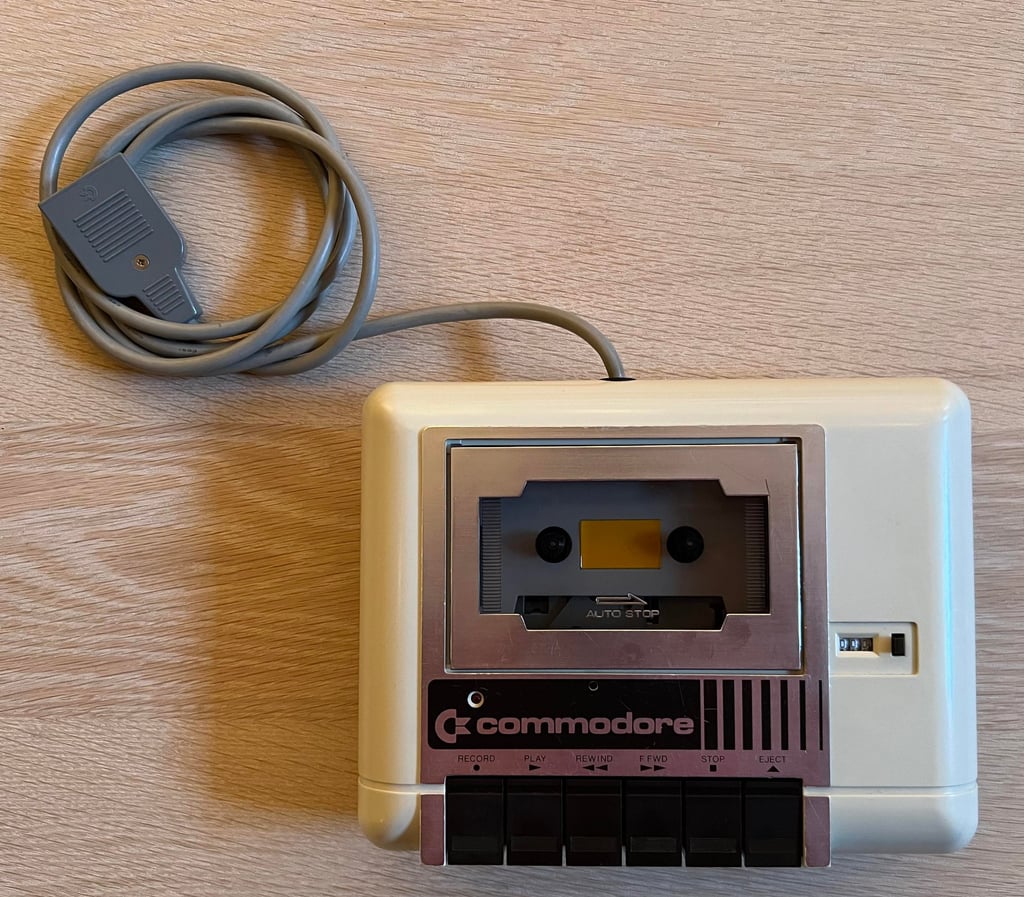
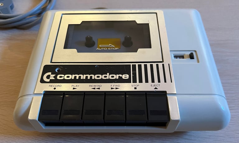
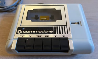
"Don´t judge a book by its cover" is a well known idiom. From the outside this 1530 C2N datasette doesn´t look to good, but it really seems to be in quite good condition. All the parts, keys and the covers appear to be quite ok beneath the grease, dust and residue from stickers. I don´t yet know if this datasette still works after 40 years, but I have high hopes.
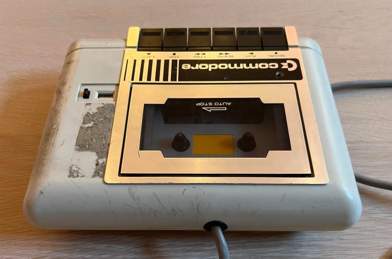
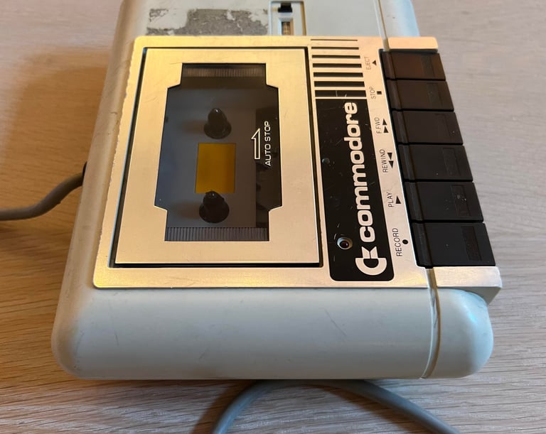
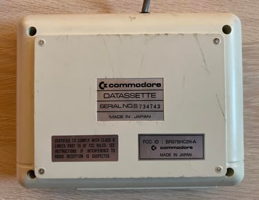
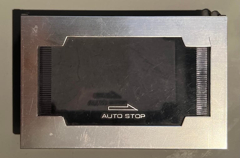
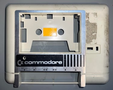
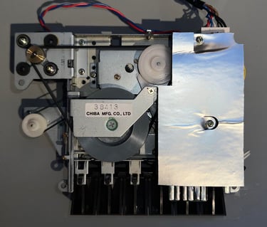
There are some "burn marks" on the covers from the cable which probably has been in contact with these, but it doesn´t look severe. Also, this is the "Made in Japan" version. You can obviously see this from the see this from the label at the bottom cover, but you can also see this from the front: the placement of the record LED and the design of the counter is different from the "Made in Taiwan" version.
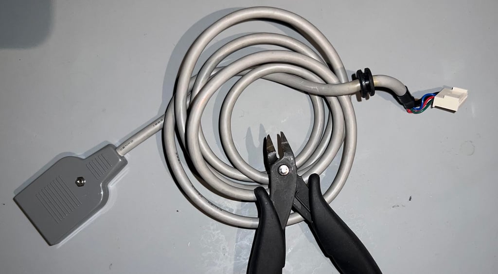
The ground cable is cut (not shown in the pictures), but that is fine. This ground wire is not used anyway and would be wrapped around the cable if present to avoid short circuit the user port.


Refurbishment plan
To refurbish this 1530 datasette the plan is to:
- Clean and remove stains from exterior casing
- Clean the interior mechanics
- Check cable and replace strain relief
- Check PCB for corrosion and replace old electrolytic capacitors
- Replace motor- and counter belts
- Check, and if necessary, adjust R/W head for optimal tape reading
- Check, and if necessary, adjust motor speed for optimal tape reading
- Verify datasette operation by testing
Note that these steps are not necessarily done in the order described above, and several of these steps are done in parallell.
Disassembly
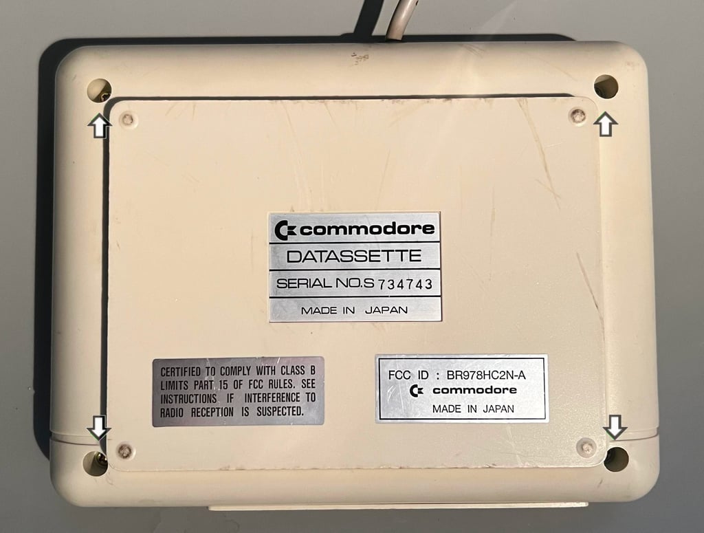
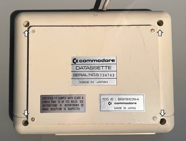
The datasette is composed of a top- and bottom cover held together by four screws. These four screws are removed and the datasette can be opened.
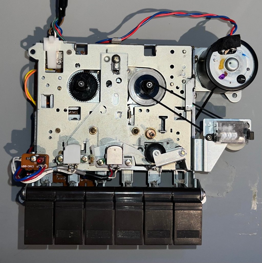
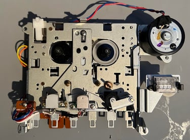
Holy moly! When removing the bottom cover the interior is revealed. And it looks - pristine (!) There are almost no dust and grease inside this datasette. I think that this is the cleanest interior of a datasette I have ever seen (before refurbishment). A quick touch on the counter- and motor belts shows that the motor belt is not too bad, but the counter belt has completely lost it elasticity.

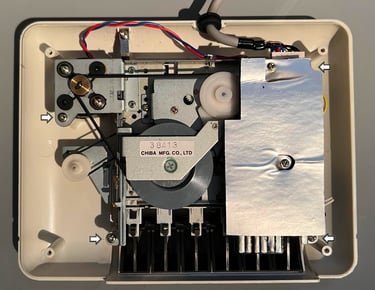
To loosen the interior mechanics from the top cover the four screws (indicated by arrows in the picture above) are removed. The interior is lifted away and the top cover is revealed. No surprise here - the top cover is just as good looking on the inside as the rest. This datasette is looking way better on the inside than the outside.

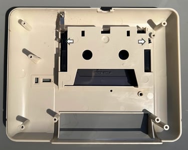
To remove the tape lid from the top cover the two plastic stems (see arrows in picture above) are carefully pressed inwards. With some gentle wiggling the tape lid is removed from the top cover.

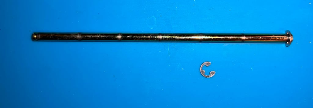
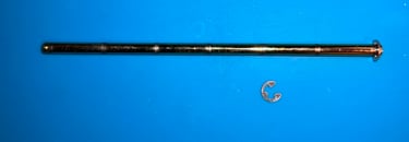
The final part of the disassembly is to loosen the six function keys from the shaft. To do this the E-clip on the right hand side of the key row is removed (see arrow in picture below for the location of the E-clip).


With the E-clip out of the way the shaft is carefully pulled out and away of the six keys.
Exterior casing
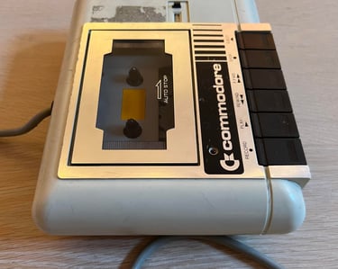
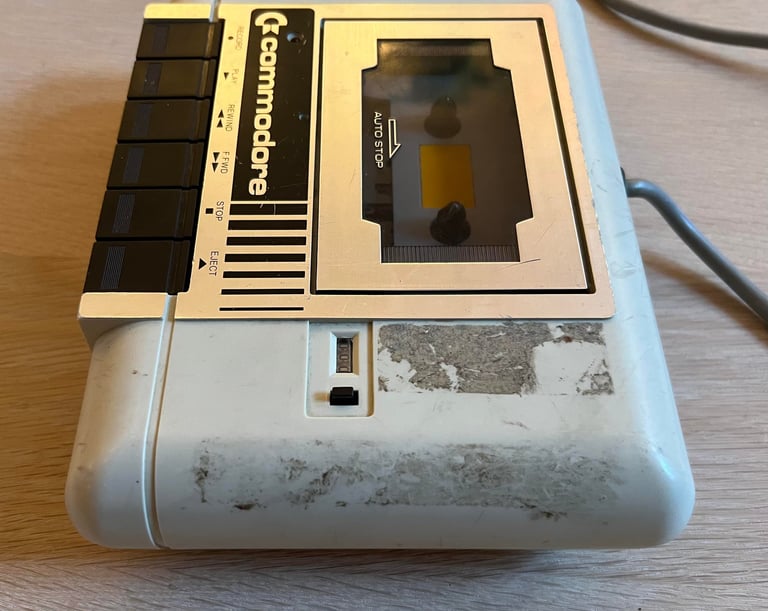
As seen from the starting point chapter the exterior casing is very dirty and with quite some signs of use - something that looks like cable burn marks and/or scratches.

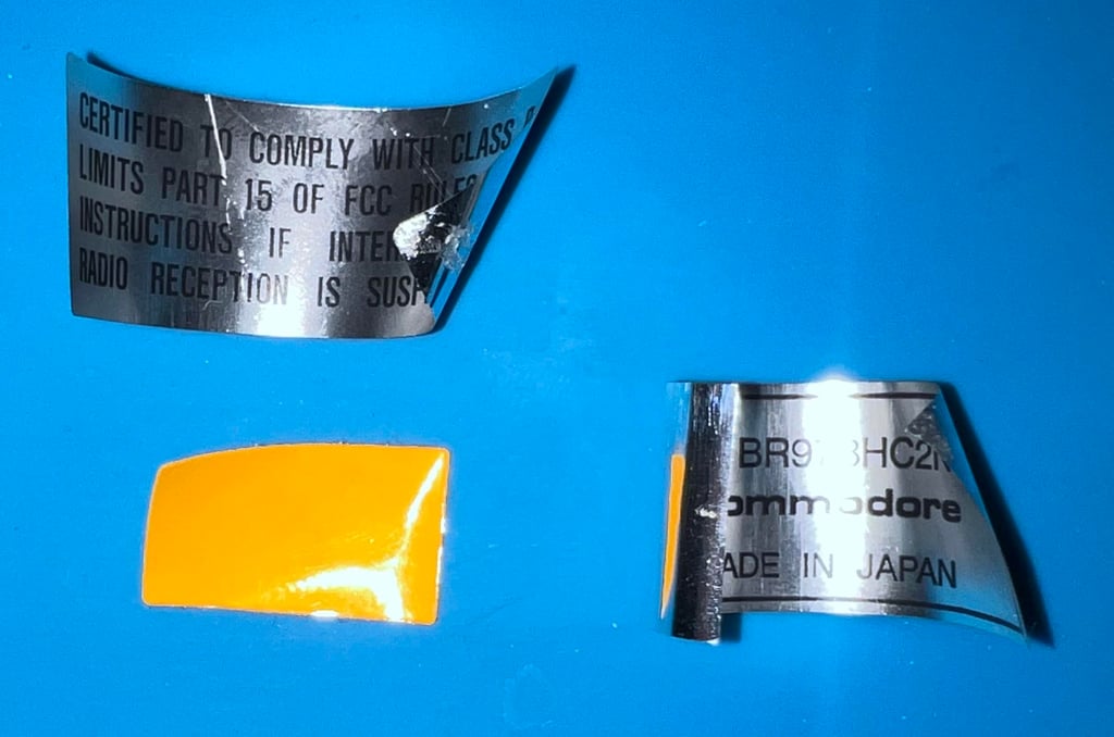
Before the cleaning process the stickers at the top- and bottom cover are removed carefully using some hot air (from a hair dryer) and precision tweezers. Note that the metal badge is not removed as this will not be damaged during cleaning. The stickers will be replaced later using some double sided tape on the back of the stickers.

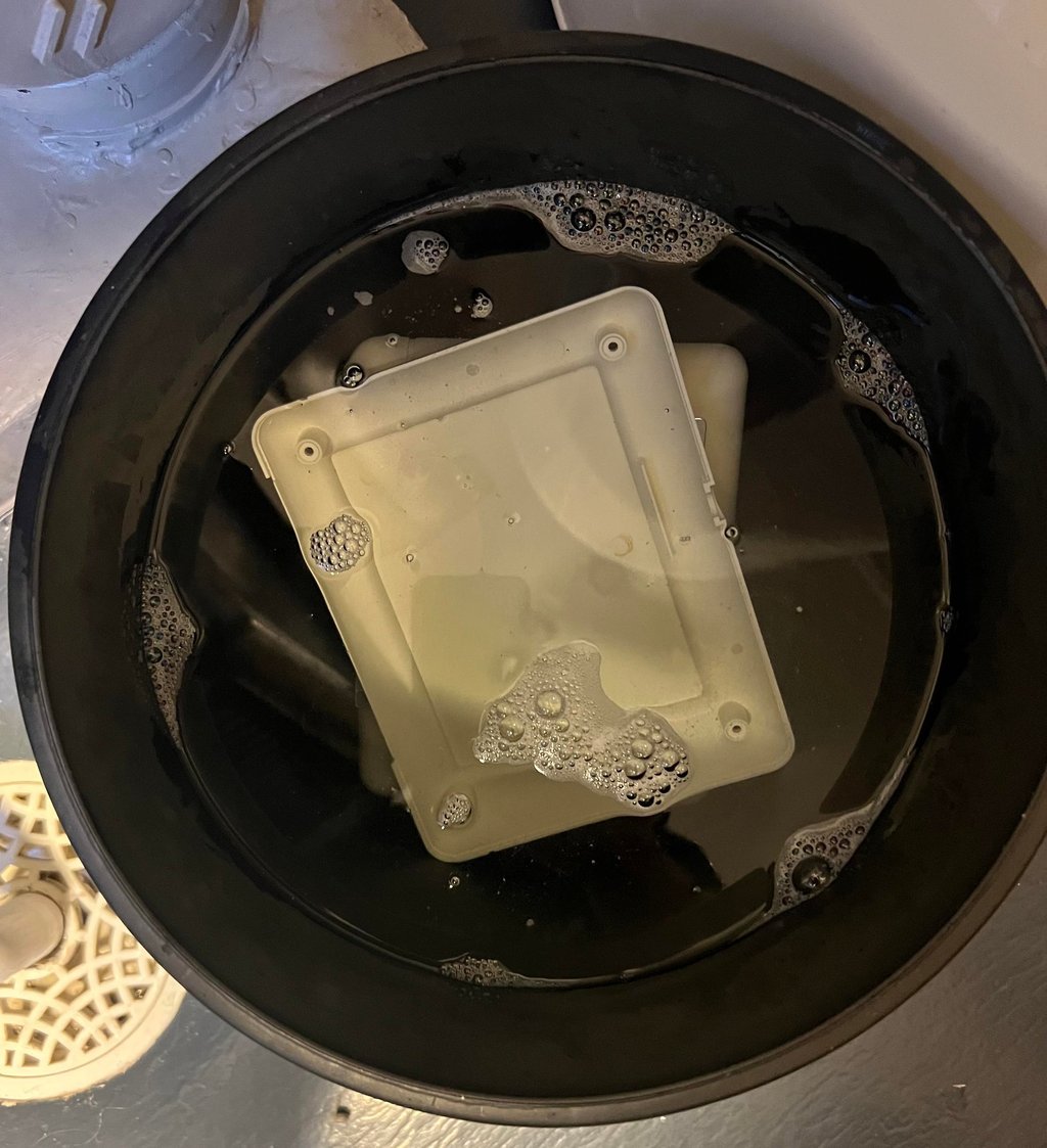
"It´s time to take a bath!" - the covers and the keys are placed in a bucket of water with some mild soap for about 48 hours.

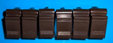
The keys looks very good after cleaning. Some additional isopropanol and glass cleaning spray is used to remove the last remaining dirt.

To remove the sticker residue on the covers some isopropanol is used, and to remove the scratches some acryl polish is used. The result looks very good I think!


Interior mechanics
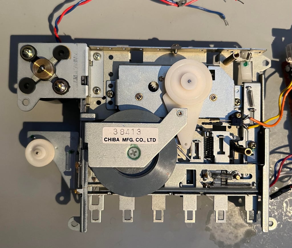
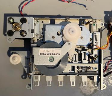
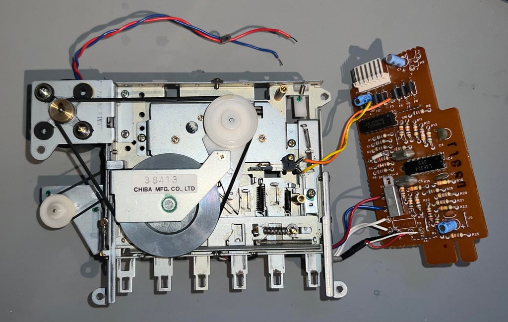
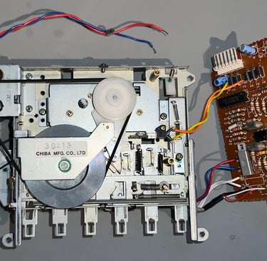
The interior looks to be in very good condition. Usually, these datasettes are full of dust, grease and the occasional corrosion, but not on this one. Below are some pictures of the interior before cleaning and lubrication (note that this picture is taken before the disassembly of the keys and removal of the belts).
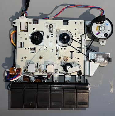

Even if the interior is in very good condition already it is cleaned properly nevertheless. This is done by using isopropanol and a Q-tip to remove all dirt and old grease. New multi purpose grease is applied to moving metal-to-metal parts.
WARNING #1: make sure to not use too much grease as you do not want this to come in touch with belts, the tape, pinch roller or capstan. Below are some pictures of the interior after cleaning and lubrication.
WARNING #2: make sure that both belts and keys are removed when cleaning and lubricating. You do not want grease on these.

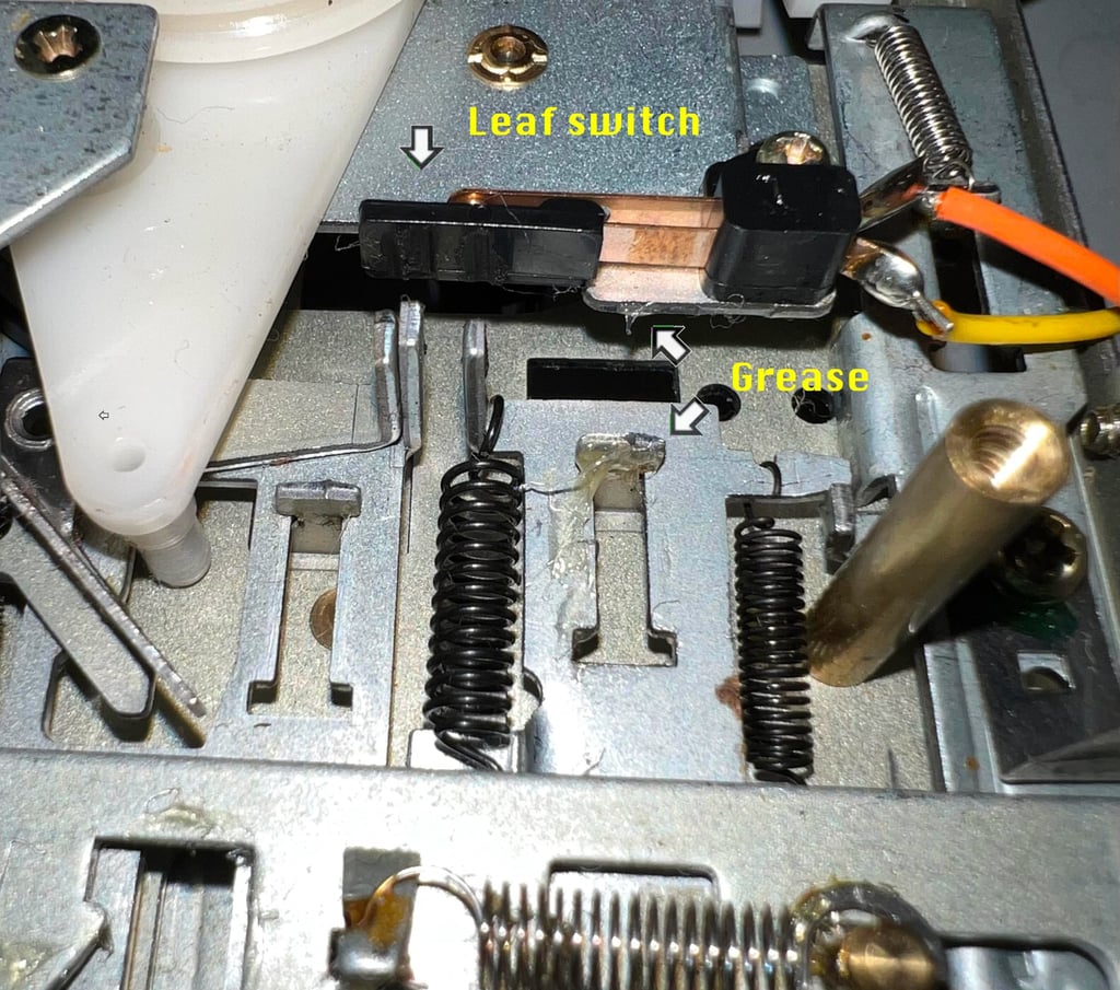
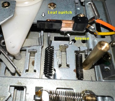
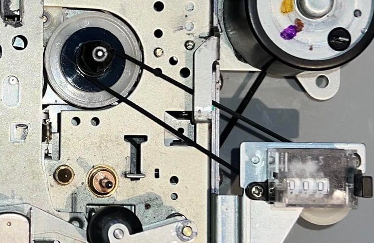
Also, pay special attention to not get grease into the leaf switch. When lubricating the moving metal parts is very easy to drop some grease in the wrong places (see picture below - note that this picture is NOT manipulated! I actually spilled some grease which had to be removed).
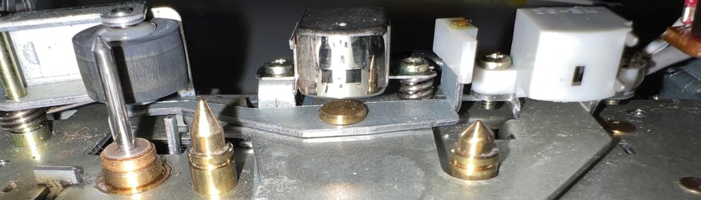
A prerequisite for the datasette to operate without errors is that the read/write head, the erase head and the capstan plus pinch roller are clean. If these are not clean you risk that the datasette will have problems reading/writing signals from/to tape - or that the tape "slips" during playback. All of these important components are cleaned thoroughly with Q-tip and isopropanol.

PCB and electrolytic capacitors
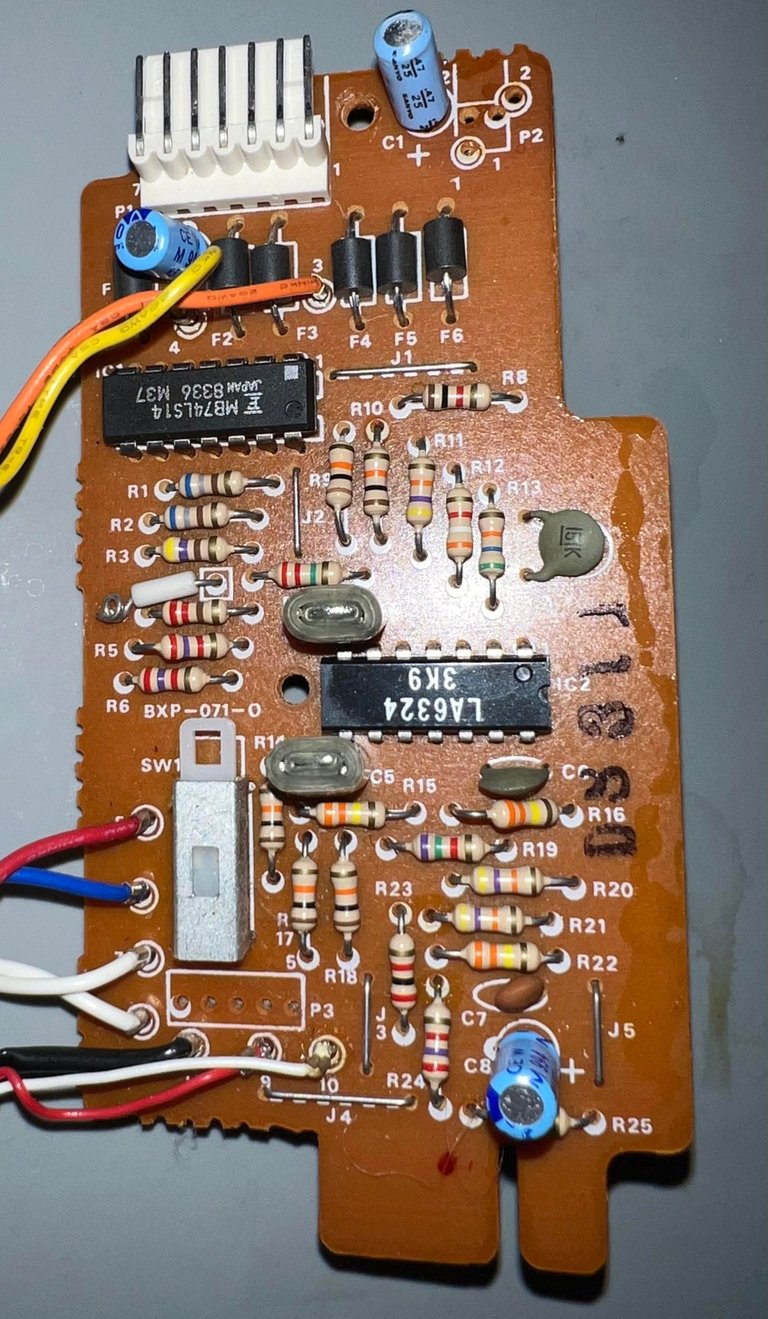
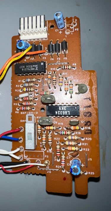
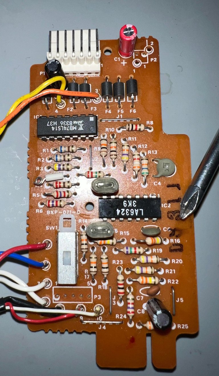
To expose the PCB the cardboard shield is removed (held in place by the two screws - see arrows). As can be seen the PCB is quite full of old flux residue. This is not any concern as the flux residue is more "cosmetic" than a problem. It will be removed nevertheless.
As can be seen from the picture the PCB is a CRM-001-0 version. Consulting the capacitor list we can see that this PCB contains two electrolytic capacitors; 1 x 0.47 uF [25 V] and 2 x 47 uF [10 V].
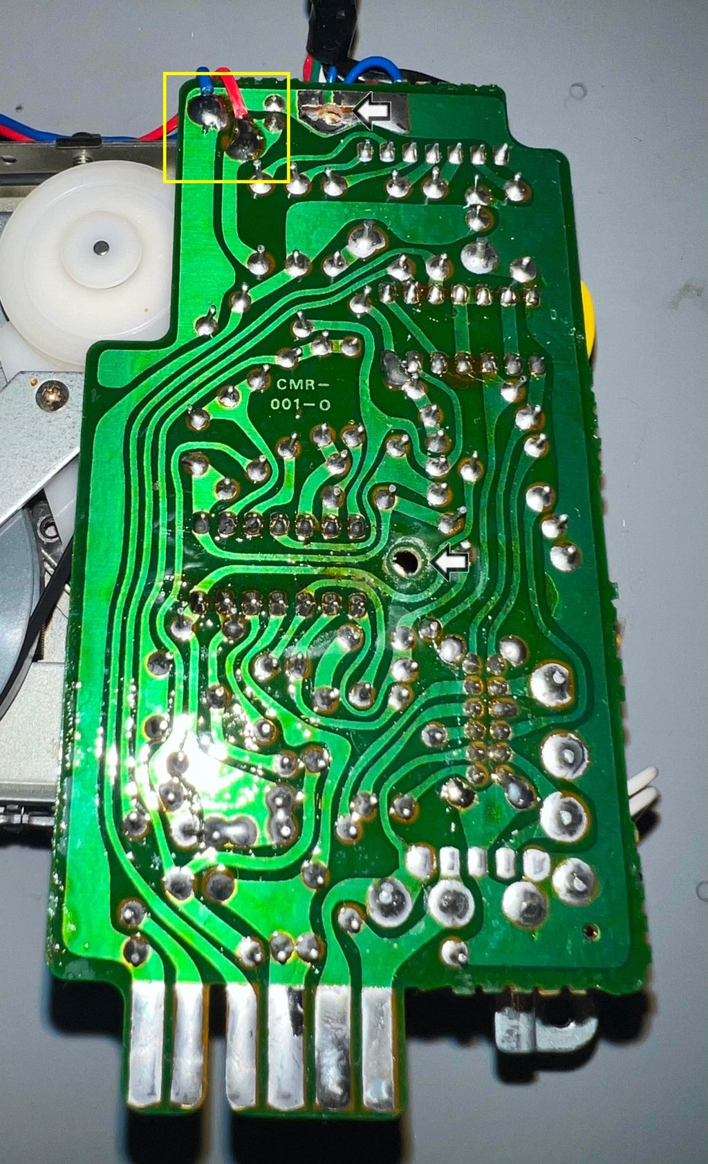
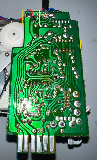
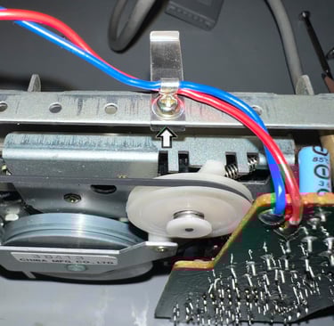
For easy access to the front side of the PCB the two wires connecting the motor are desoldered (see yellow square area in picture above). Then the connector holding the datasette cable at the rear of the PCB are disconnected - and finally, but not strictly required, the cable strain relief for the same motor wires are removed. See arrow in picture below for the position of this.

After these steps the cleaning of the PCB and the replacement of the electrolytic capacitors is easier.
The three electrolytic capacitors are replaced without any damage to the PCB. Below are some pictures from the operation. Picture to the left shows the original capacitors and the picture to the right shows the PCB with the new capacitors installed.

Cable and connector
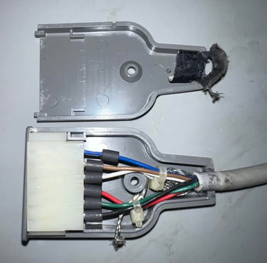
From the outside the datasette cable and connector looks to be in good condition. There are some dirt and grease, but nothing more than what is to be expected. The ground wire is missing though. But, this is not an issue at all. The ground wire is not used in the Commodore 64 - in fact the ground wire is a hazard since it can easily short circuit the user port just next to the datasette port.
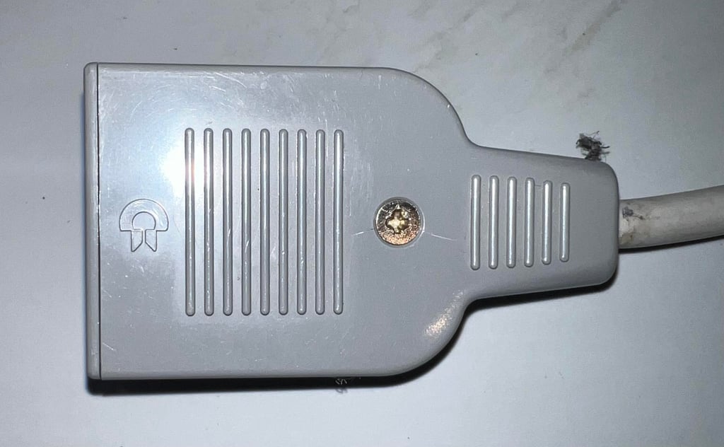
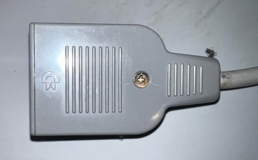
By removing the single screw and nut the connector is opened. As can be seen from the picture below the ground wire is cut (not am issue) and apart from being a bit dirty the connector looks ok.
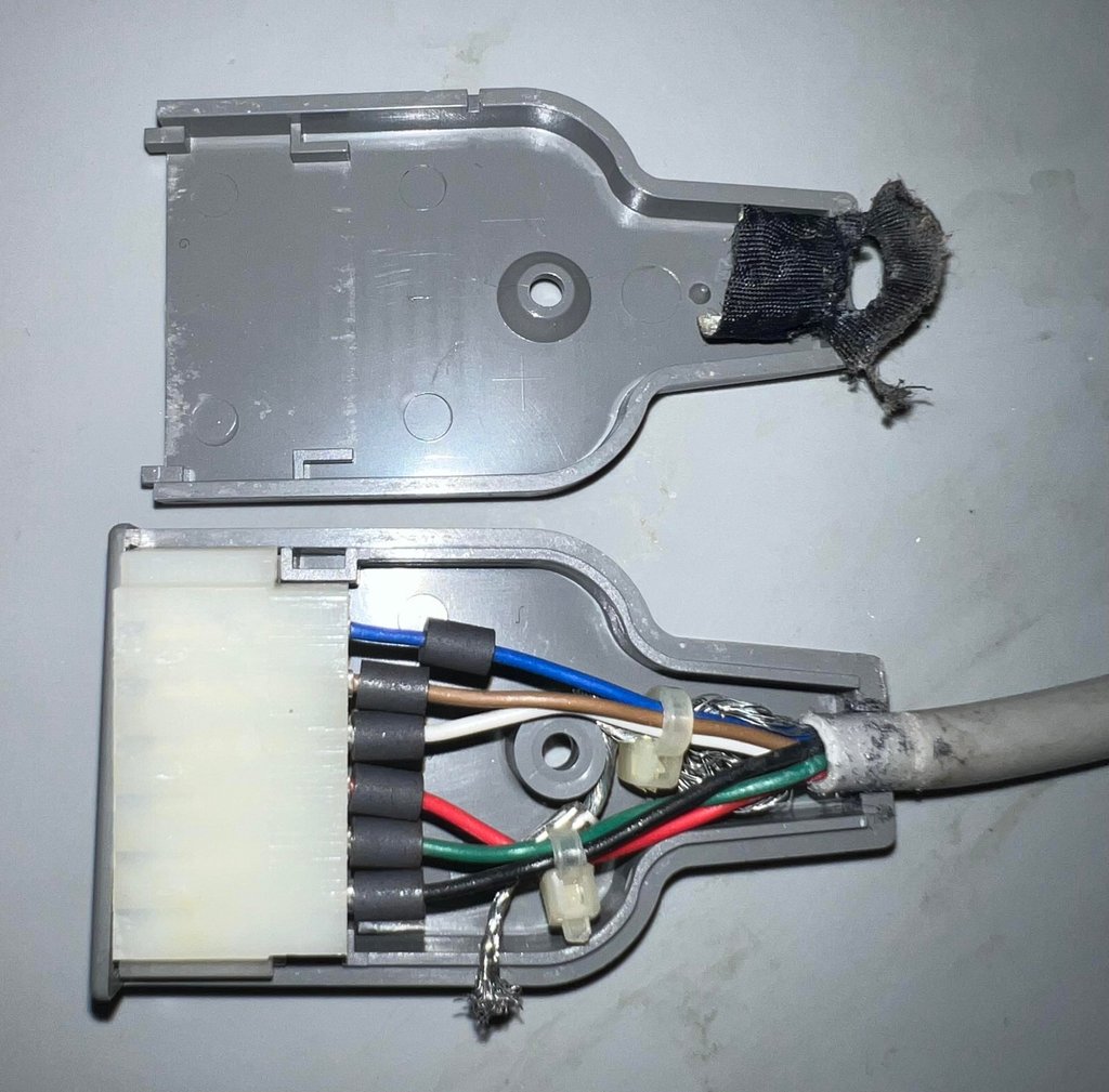
All wires are checked and everything is cleaned with isopropanol and some contact cleaner. A cable tie is used to function as a strain relief.

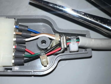
The cable is cleaned with isopropanol and some glass cleaning spray. Then everything is assembled and the cable is as good as new.

Replacing the belts
For the datasette to operate flawlessly - that is to avoid "?LOAD ERROR" and failing in loading in general - the belts needs to be in proper condition. After 40 years these belts are most likely to have lost their elasticity and shape.
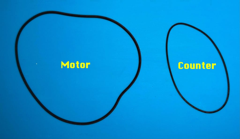
There are two belts on a datasette; one for the counter mechanism and one for the motor driving the flywheel.

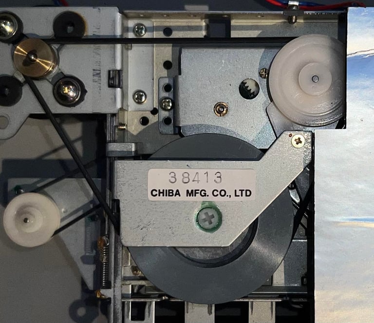
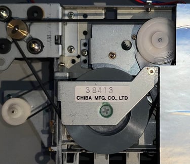
Removing the belts in a "Made in Japan" datasette is very easy (compared to a "Made in Taiwan" model). To remove the counter belt is just a matter of lifting the metal clamp before removing the belt. For the motor and flywheel it is even easier: just lift the belt straight off. As can be seen from the picture below the belts are heavily deformed. The elasticity of the motor/flywheel belt is not too bad for it age, but its way out of shape.

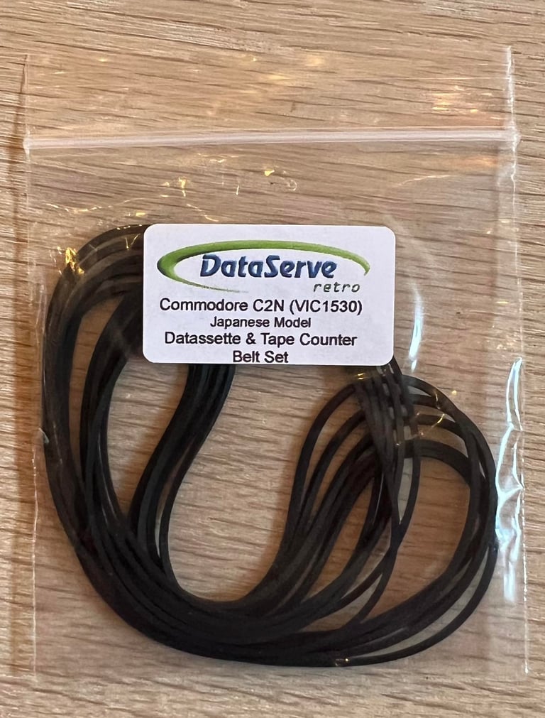
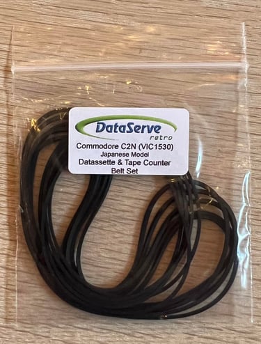
To order new belts I highly recommend using DataServe - Retro. They have the right belts, with good quality and fast delivery. See picture below (notice that these are clearly labeled for use with the Japanese model and this bag contains belts for several datasettes). The new belts are installed easily (as simple as removing them).
R/W head alignment
In addition to replacing the belts it is crucial to check the read/write (R/W) head alignment and if necessary adjust it. Otherwise the datasette can´t load our beloved tapes without the notorious "?LOAD ERROR", or simply just fails loading.
A detailed article about how I align the R/W head can be found here. As seen in this article I use both an oscilloscope and C64 software to do this operation in two stages:
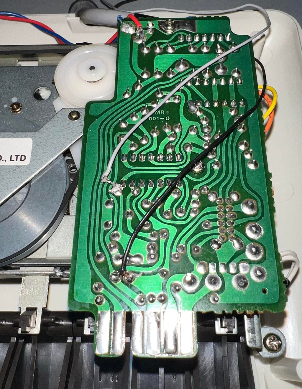
The first stage I solder on two wires after the 2nd OP-AMP stage, connect the oscilloscope to these wires and then adjust the R/W head until I find the maximum amplitude on the oscilloscope. Note: if the amplitude appears to already be at maximum before tuning it is good practice to wait with further adjustment of the R/W head.
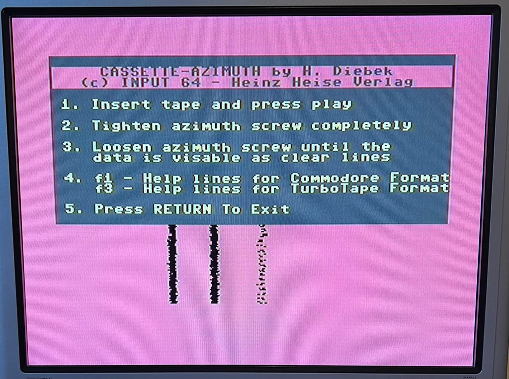
Second stage I use cassette-azimuth software running on a Commodore 64 while loading games from tape. In this second stage I do not do any adjustments - I only validate that the adjustment done in the first stage is correct.
Note that the datasette needs to be completely re-assembled when checking, and eventually calibrating, the R/W head alignment.
Stage 1 - Aligning the R/W head with the oscilloscope
The oscilloscope is connected to the two wires soldered to the PCB (CMR-001-0) as shown in the article and in the picture below.

Below is a picture of the measured signal while an original tape is loading. The measured signal amplitude at the 2nd OP-Amp stage is about 0.75 V (1.5 p-p) which should be within acceptable tolerances. Therefore I choose not to adjust the alignment screw at this stage, but if the verification stage (or testing stage) fails I will get back to this stage.


Stage 2 - Verification of the adjustment
To verify the adjustment with a second tool I use the cassette-azimuth software running on a Commodore 64. When the tape is loading there should appear three vertical bars on the screen. And the goal is that these three lines are as "solid" as possible. Note that these lines will never be completely solid, but the goal is that they are more or less straight vertical lines. If you have a misaligned R/W these lines will be scattered all over the screen.

Tape speed
Lately I have begun to check the speed of the tape playback. I am still a newbie in this area, but I think there is value in checking the playback speed.
The idea is smart, but simple:
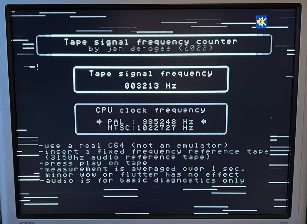
A professional Speed Calibration Audio cassette which contains a 3150 Hz sinewave recording is loaded in the datasette. During playback of this tape a software (developed by J. Deorgee) reads the registered frequency on a Commodore 64. The idea is to adjust the speed until the recorded frequency, 3150 Hz, is measured.
Note that this great idea is not mine. The idea is based on a magnificent article by Jan Derogee and his Tape Frequency Counter software.
My experience so far is that the datasette (or datenrekorder) works best when the playback speed is in the range between 3150 - 3250 Hz. You could argue that the speed should be as close to 3150 Hz as possible, since this is the expected speed/frequency reading, but for reasons I have not understood yet I see that the tape deck works better with a slightly higher speed. I will continue to do these readings when refurbishing datasettes/datenrekorder to see if I can learn something!
As can be seen from the picture below the speed is bout 3210 Hz, so I don´t see any need to adjust the speed at the moment.
Testing
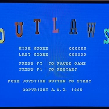
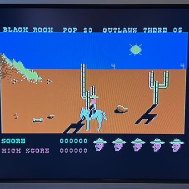
Playback
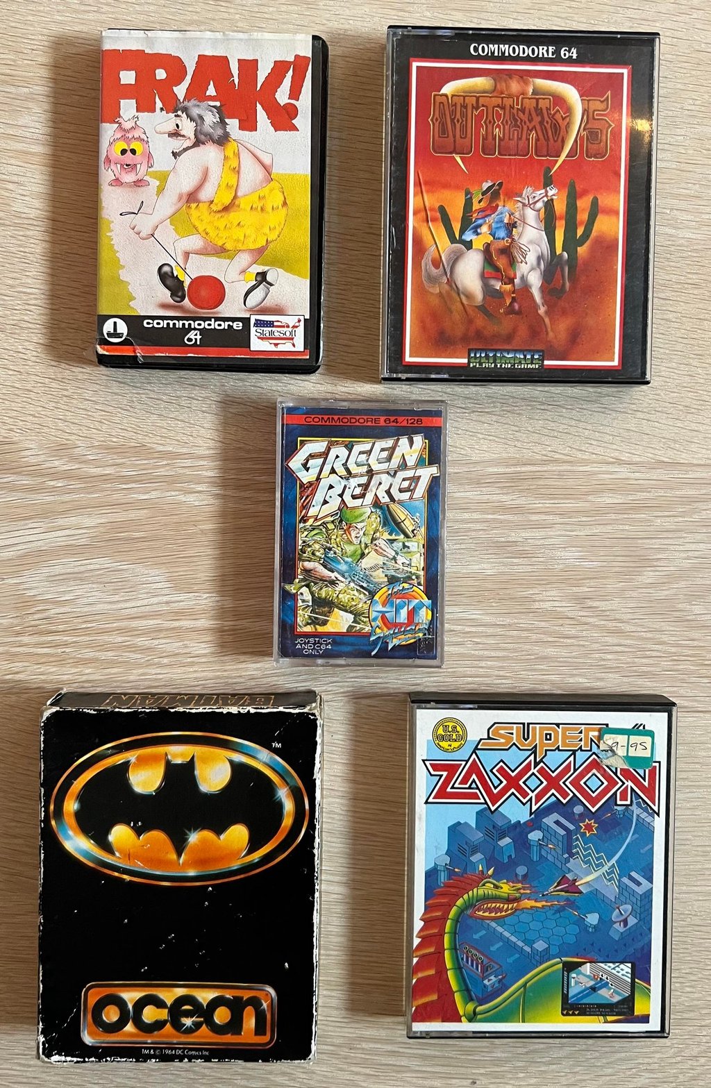
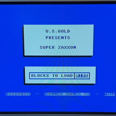
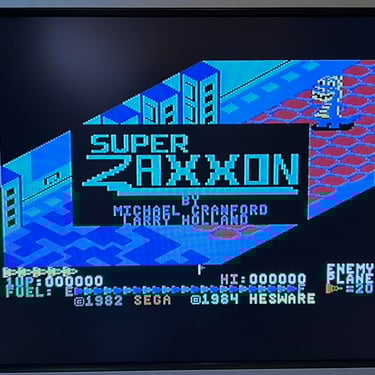
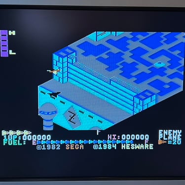
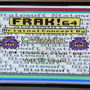
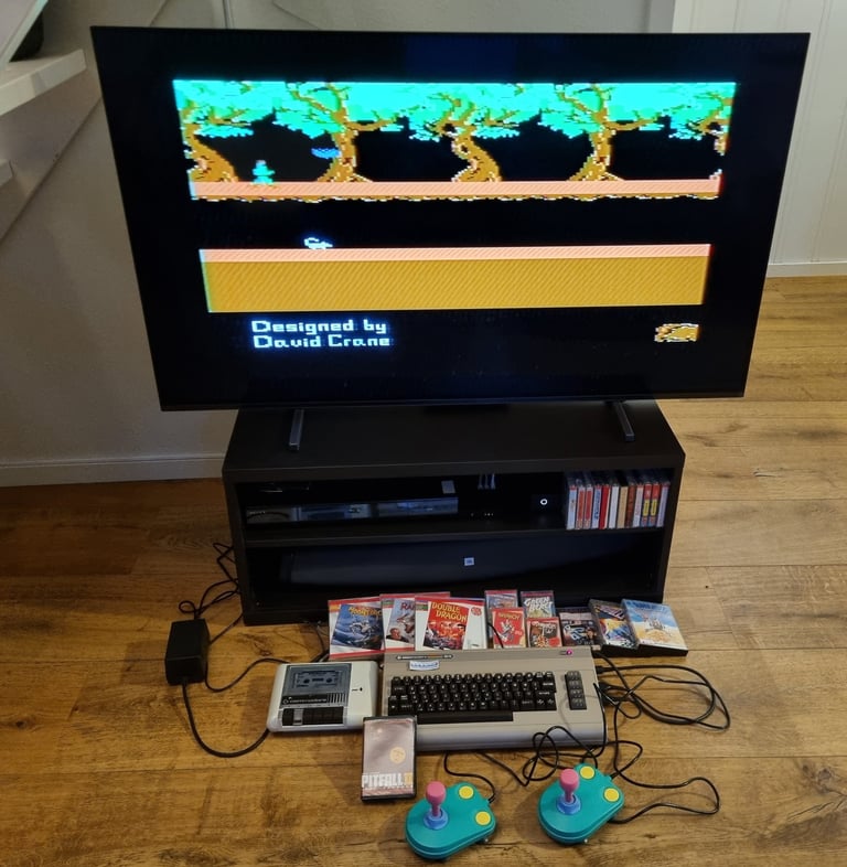
To make sure now works as it should I select five original C64 games to be used for testing. Even if these games are old and worn the load without any problems at all. Below is a picture gallery from the testing.
Recording
The saving functionality is also checked and verified. A small BASIC program is made and the SAVE command is used (and then the program is re-loaded). The LED is also on while recording is in progress.
Final result
"A picture worth a thousand words"
Below is a collection of the final result from the refurbishment of this datasette. Hope you like it! Click to enlarge!


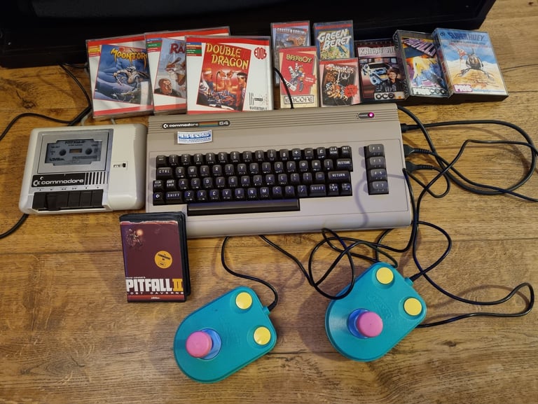
"Are you keeping up with the Commodore? 'Cause the Commodore is keepin up with you!"
Below are some picture of the datasette back at the customer´s home!

Banner picture credits: Evan-Amos