
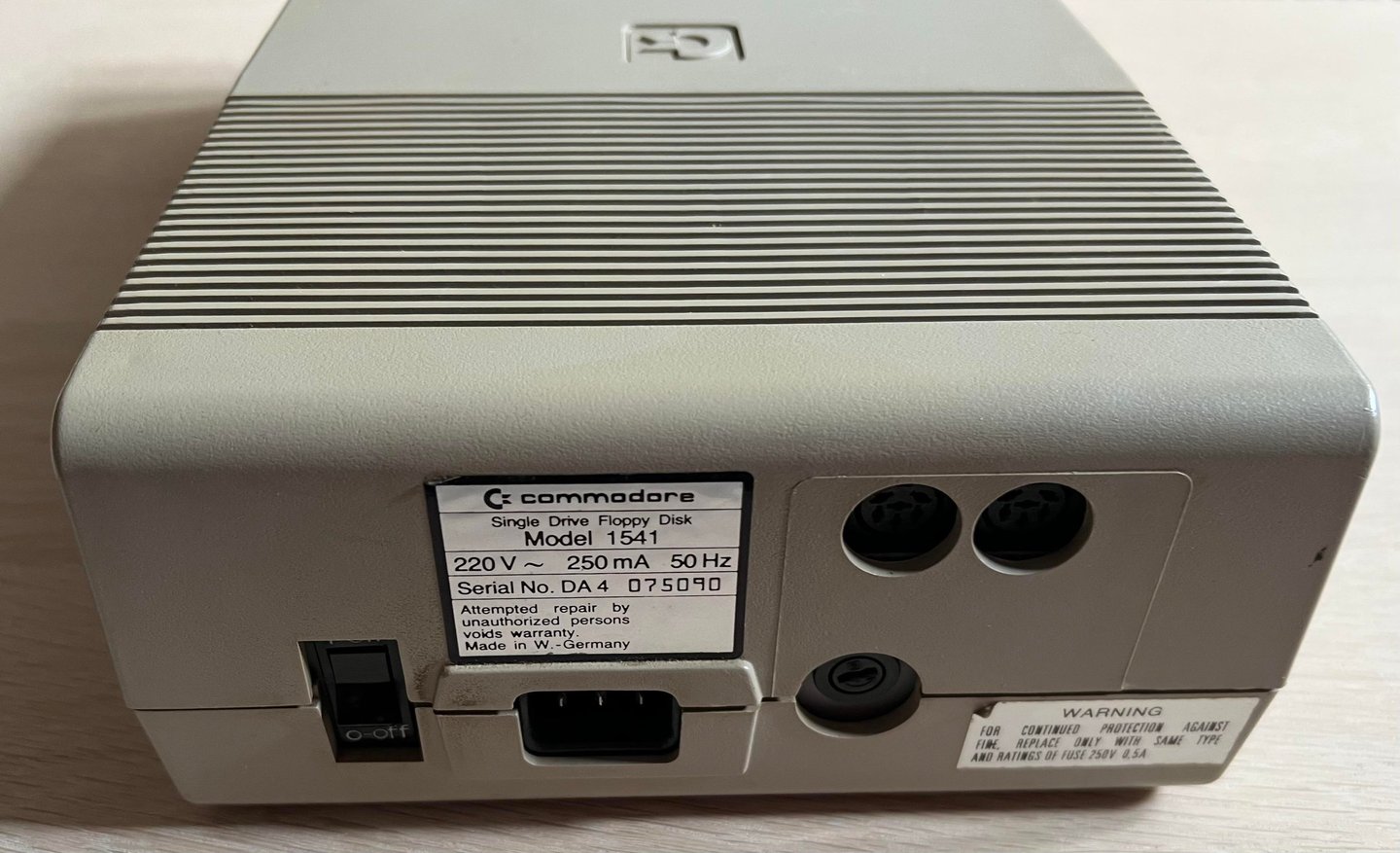
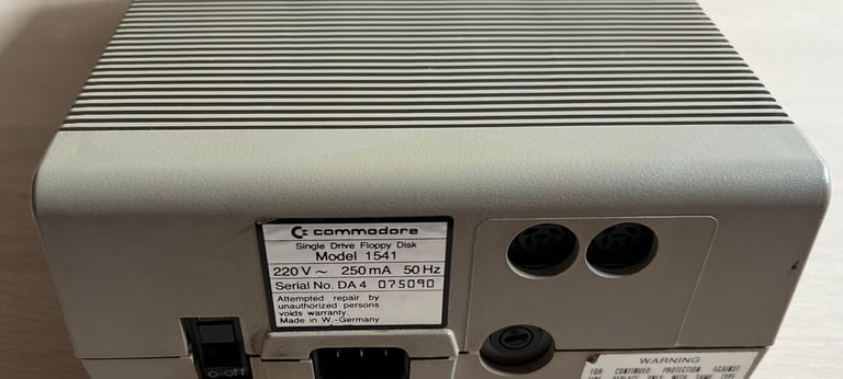
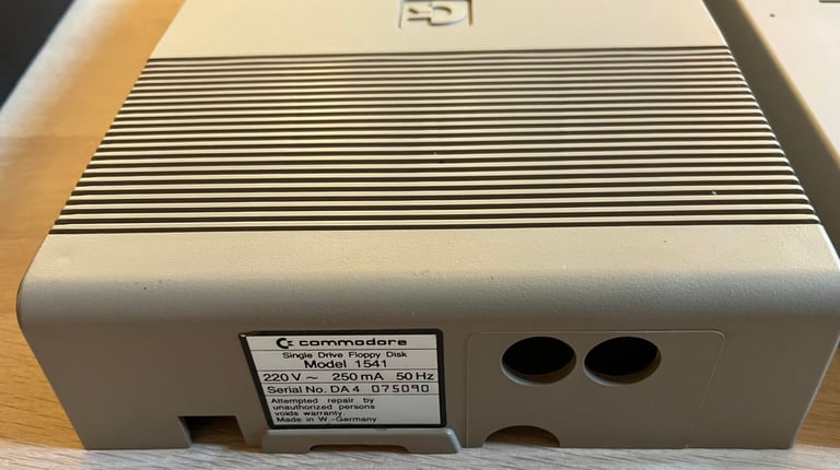
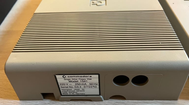
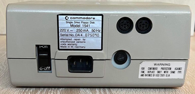
Commodore 1541
Ser. No. 075090
Assy 250442
PCB No 251830 (REV A)
ALPS-Drive
Starting point
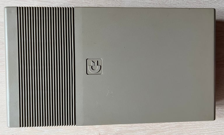
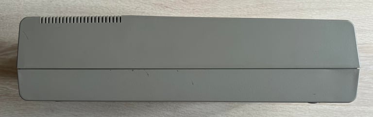
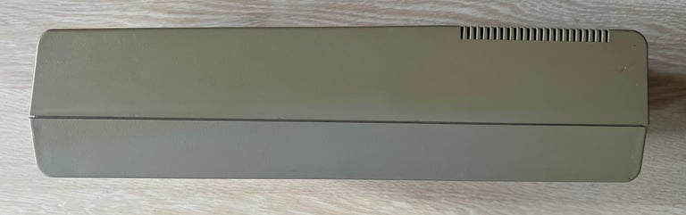
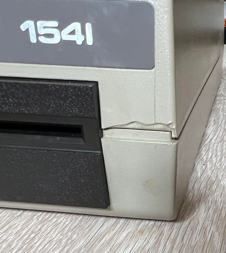
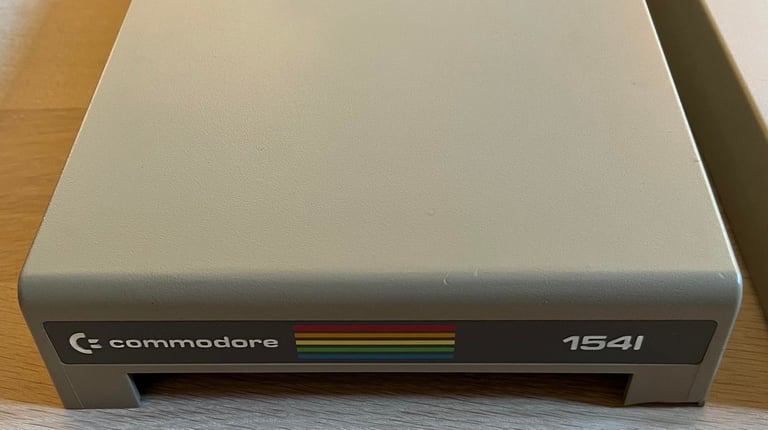
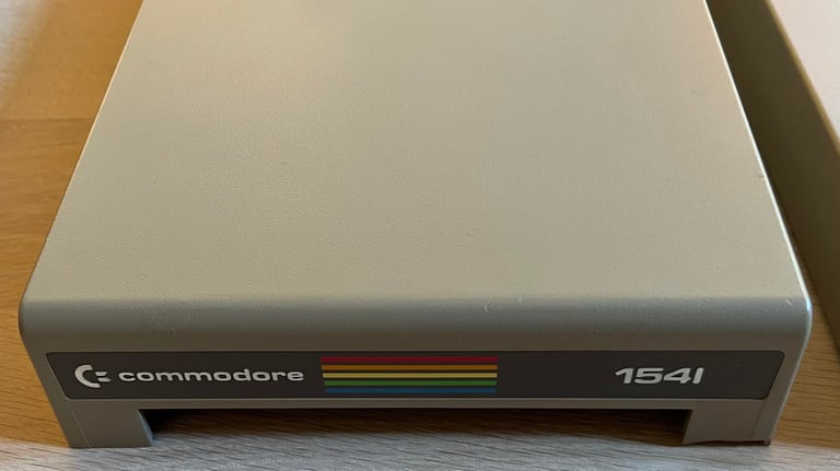
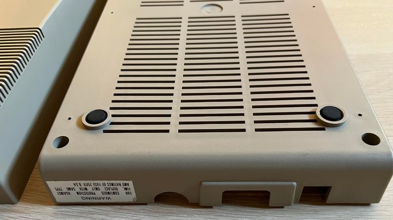
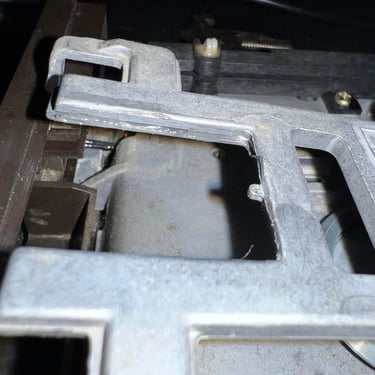
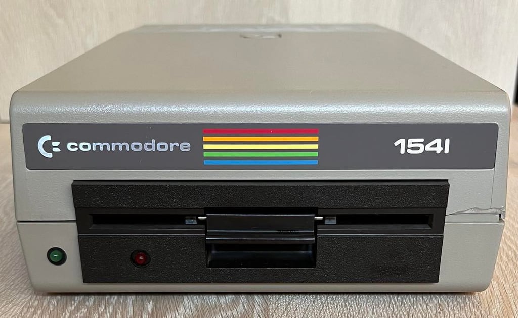
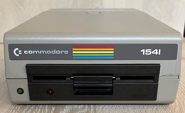
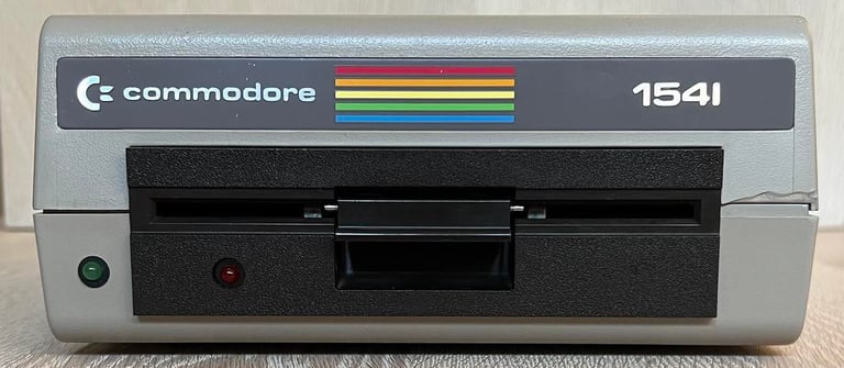
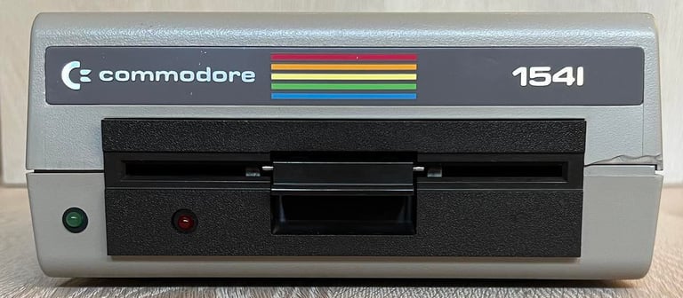
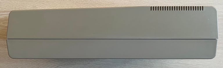
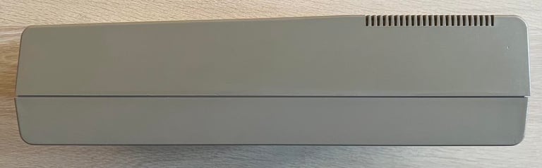
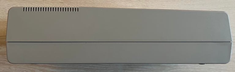
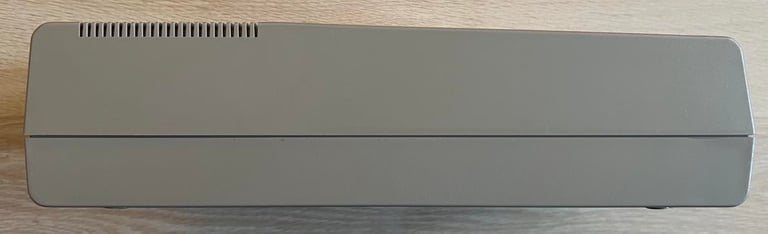
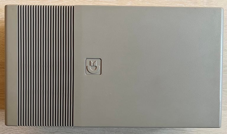
From the outside the 1541 disk drive looks to be in quite ok condition. It is slightly yellowed and dirty, and there is a small part broken off on the right hand side - but not very visible. The opening mechanism also seem to work.
Below are some pictures of the drive before the refurbishment.

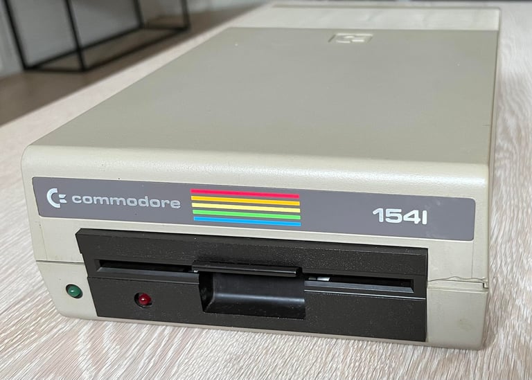
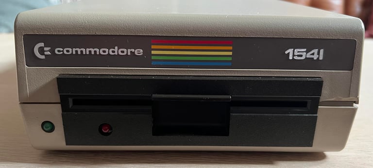


Does it already work? I can´t tell for sure yet, but when it is turned on it seems to boot up ok. I will not test it further before I rinse and lubricate the interior.

Refurbishment plan
To refurbish this 1541 disk drive the plan is to do this trough the following actions (some of them in parallell and different order):
STAGE #1: Cleaning and inspection
- Clean and retrobright the exterior casing
- Clean the PCBs (mainboard and motor unit)
- Clean the interior and lubricate moving parts
- Initial testing
STAGE #2: Replacing old parts
- Replace drive belt
- Replace electrolytic capacitors (PCB-mainboard)
- Replace electrolytic capacitors (PCB-motor unit)
STAGE #3: Testing and verification
- Verify drive operation by testing
STAGE #1:
Cleaning and inspection
Exterior casing
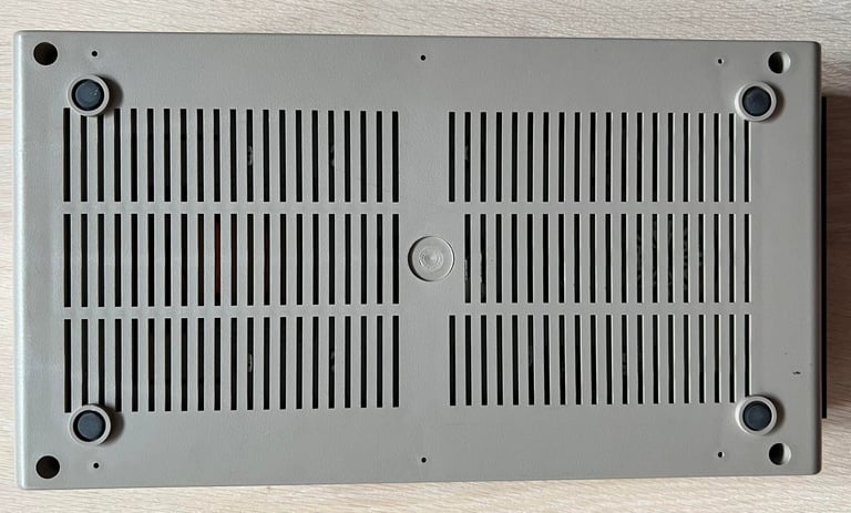
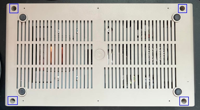
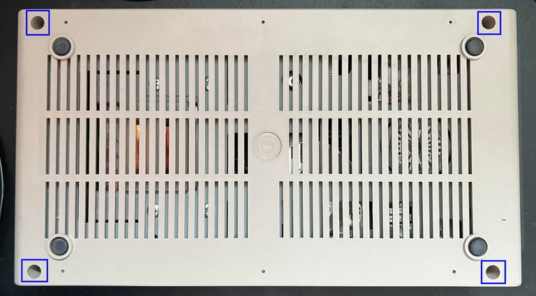
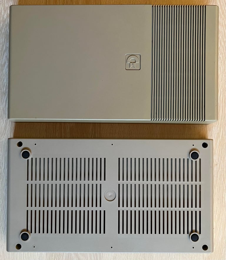
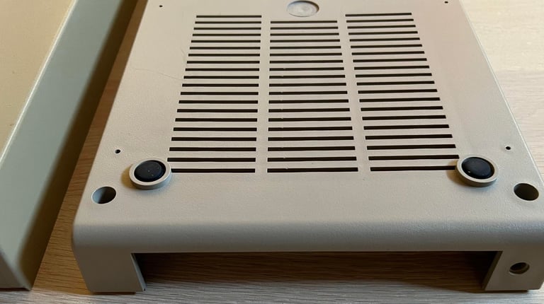
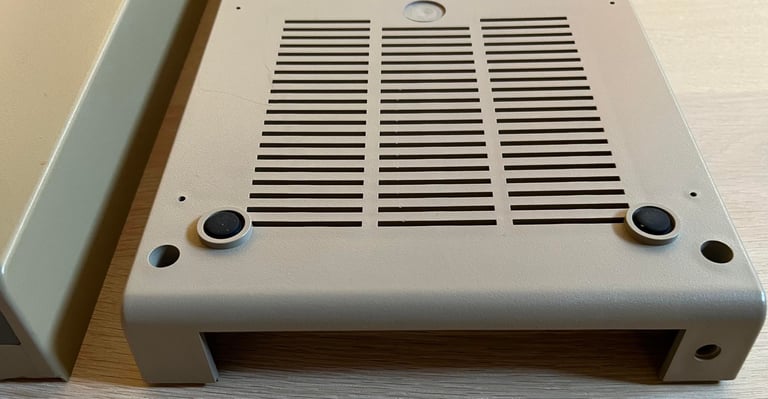
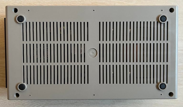
The exterior casing consist of, just as the Commodore 64, two parts; a top- and bottom cover. To separate these two the drive is placed upside down and the four machine screws are removed (blue squares).
Then the drive is flipped around again and the top cover is lifted away. This reveals the interior mechanics - still fastened to the bottom cover. The inside is full of dirt and dust.

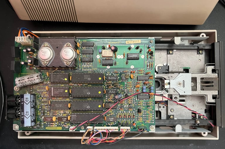
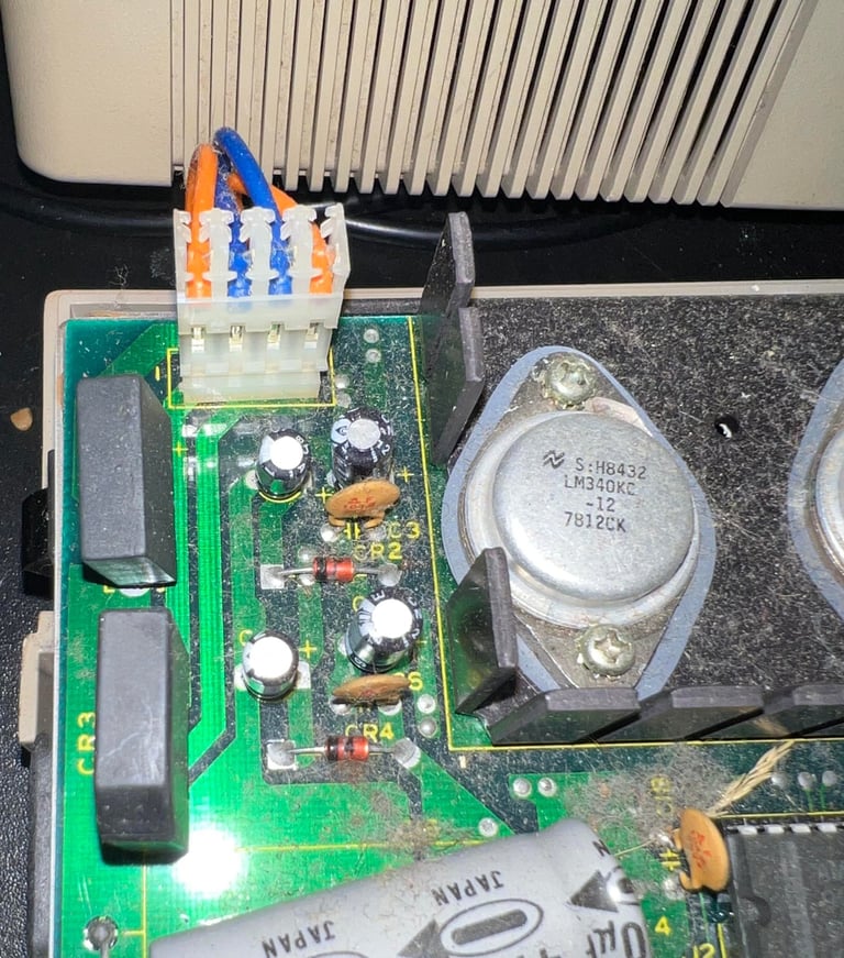
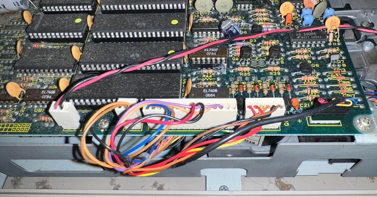
Next step is to remove the six connectors from the PCB - see pictures below.
WARNING: if you are doing service on a 1541 disk drive make sure to disconnect the power mains to avoid electrocution! Also, the large capacitors can contain energy some time after power off!

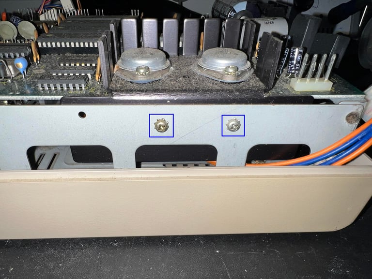
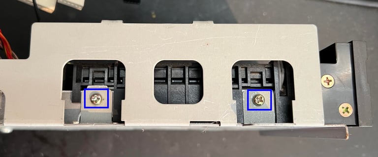
To remove the PCB the five screws on the top are removed (note that there are also some spacers on these screws). There are also to more screws on the side of the chassis - see picture below (blue squares).

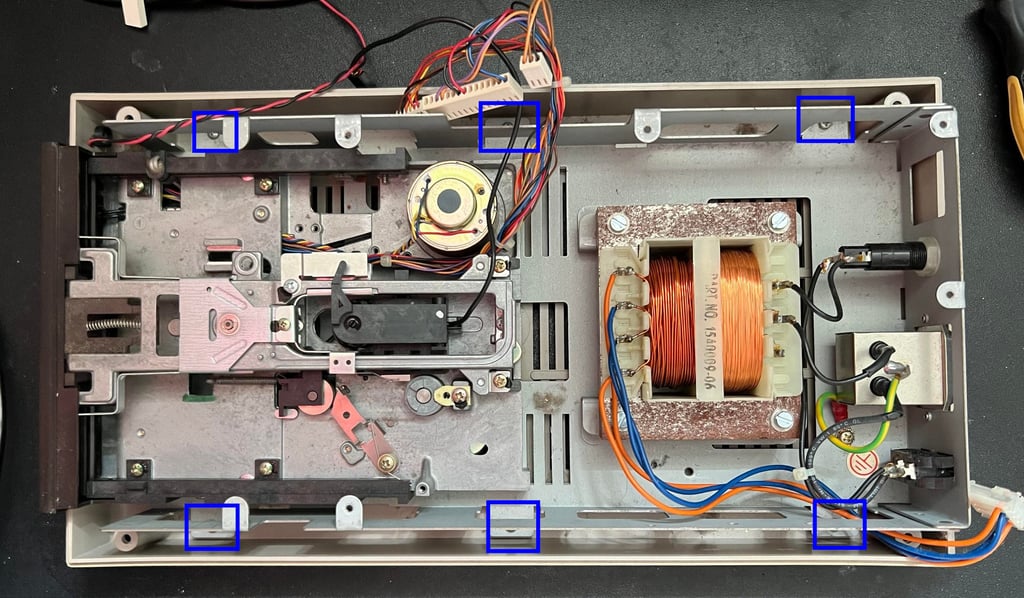
With the PCB out of the way the interior of the drive is exposed. It looks to be intact, but full of dust and grease. Then the six screws are removed (blue squares) which holds the drive chassis to the bottom cover.

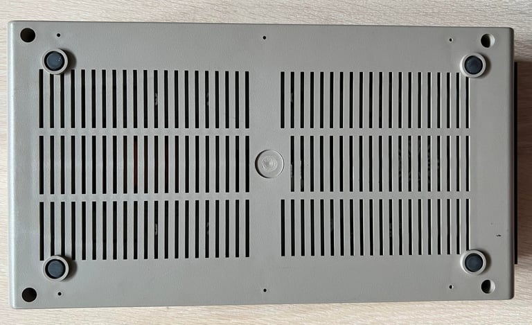
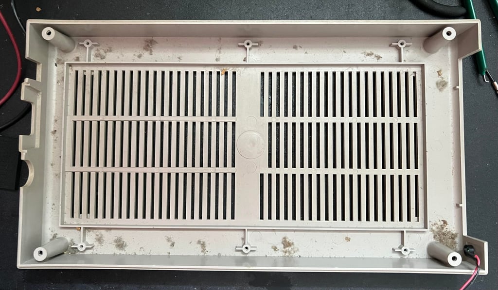
The bottom cover also looks to be in good condition - just a few dust bunnies.
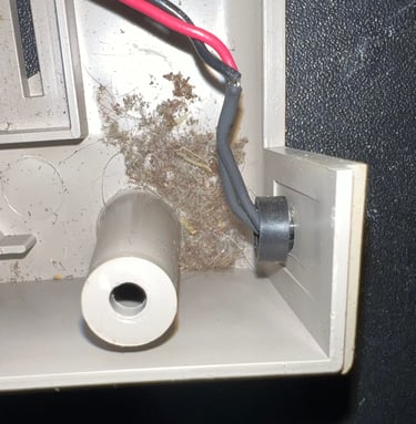
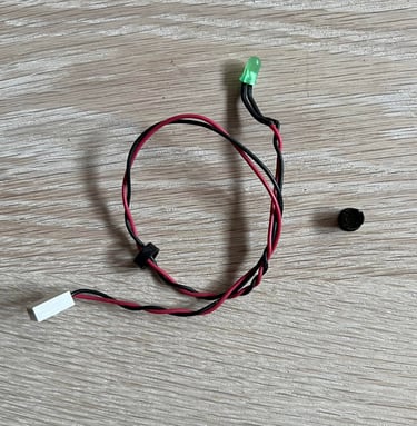
By using a small flat screwdriver the outer ring is removed from the LED. Then the LED is pushed from the outside until it "pops out" of the black plastic holder. Finally the plastic holder is pushed out of the bottom cover.


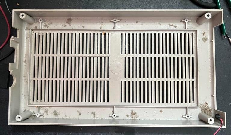
Now the top- and bottom cover are finally ready for cleaning. This is done by first washing them with mild luke warm soap water. And then they are cleaned with glass cleaning spray. Below are pictures after the cleaning. I think they looks quite nice already! Still, they would require some retrobrighting but this is a fine starting point.


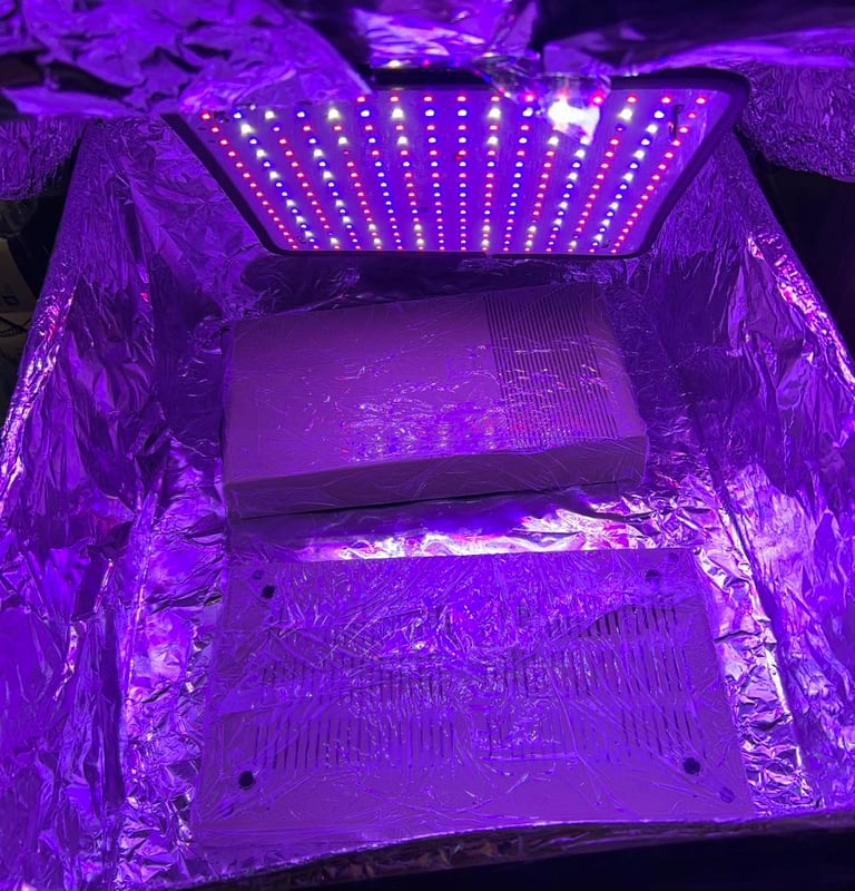
Both covers are retrobrighted by using some 12 % hydroperoxide cream and UV-light for about 10 hours.

PCBs - Inspection and cleaning
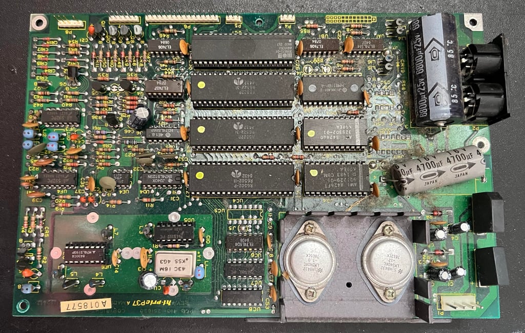
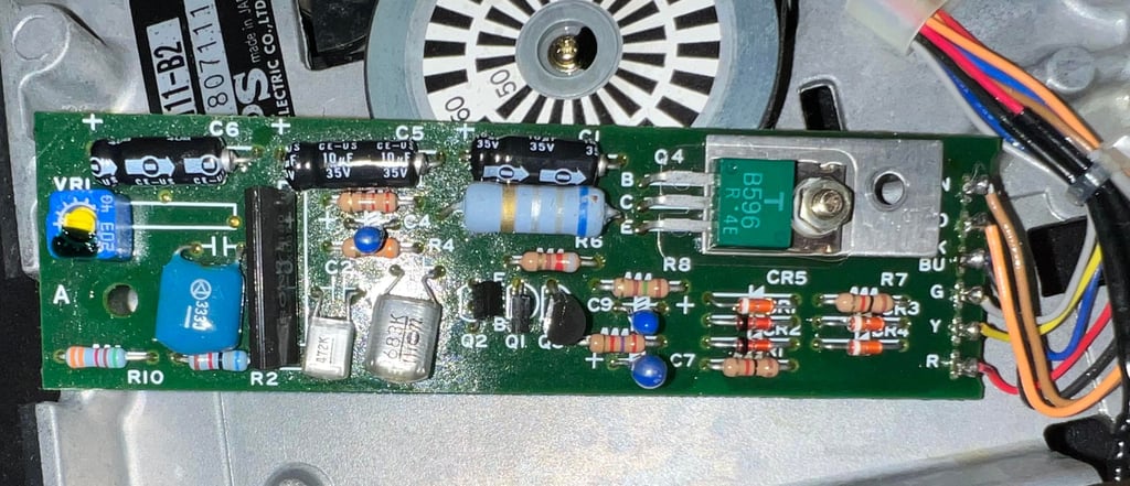
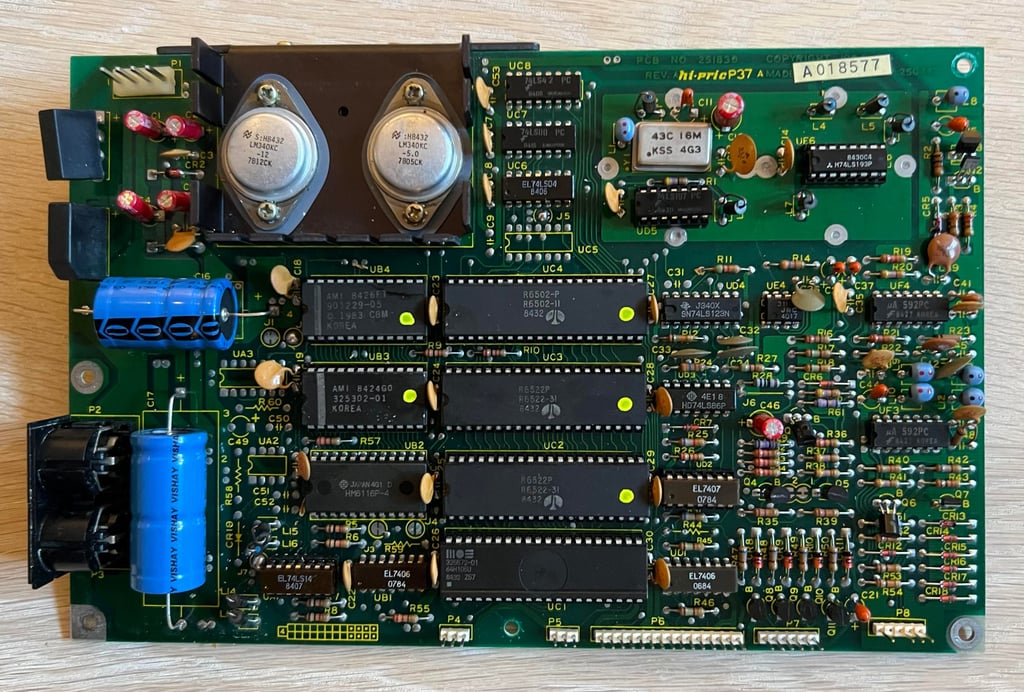
Mainboard
This is a PCB NO 251830 (Rev A) / Assy 250442 mainboard. It is incredible dirty and full of dust, so before I do anything with this I need to clean it properly. Below are some pictures of the mainboard before cleaning.

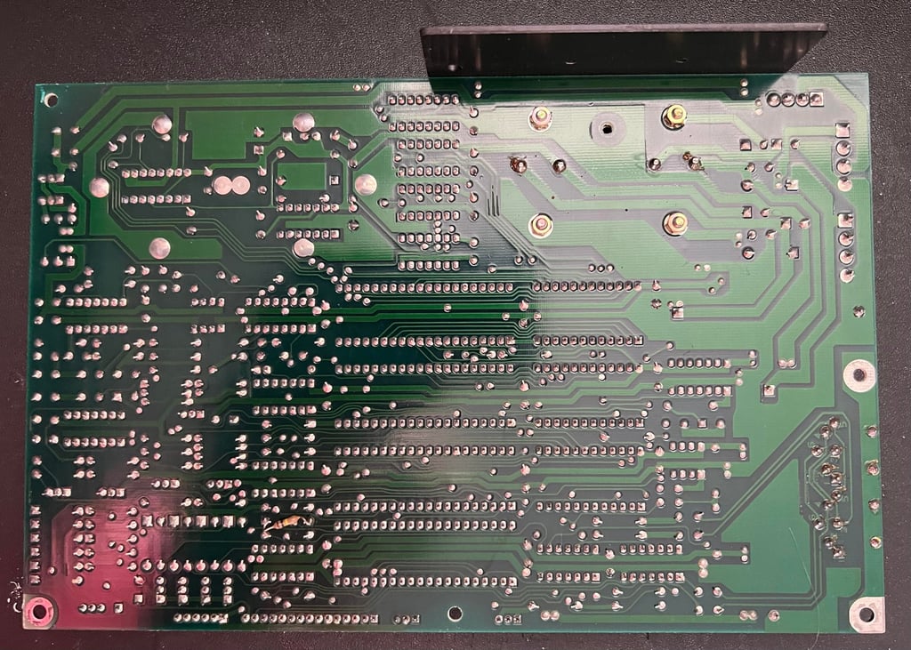
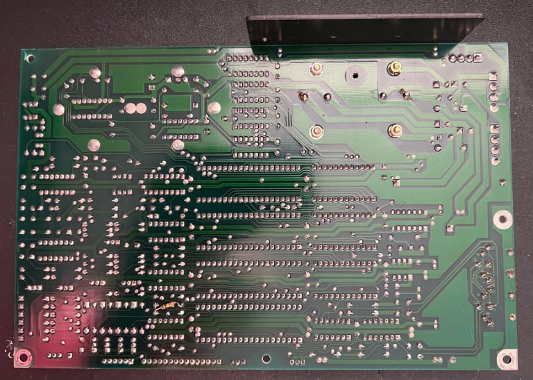
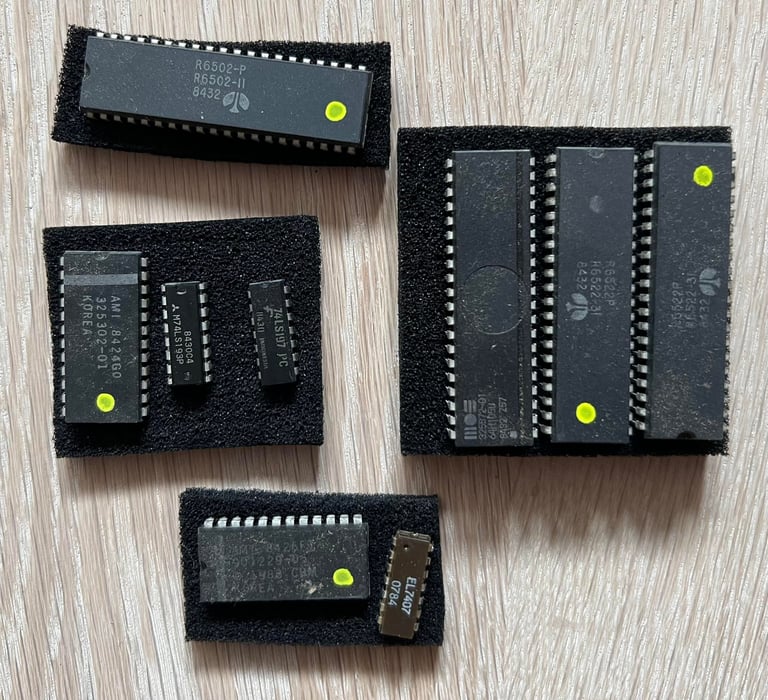
The way I clean it is by washing it with mild soap water and a paintbrush. Then rinse it properly with water - and after that I use plenty of isopropanol to make sure the water evaporates. Before cleaning all of the socketed chips are removed also - these are cleaned separately with isopropanol.
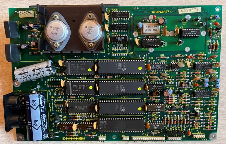
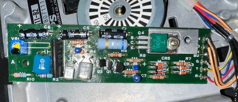
Result of the cleaning is very good. The PCB looks brand new. See pictures below.


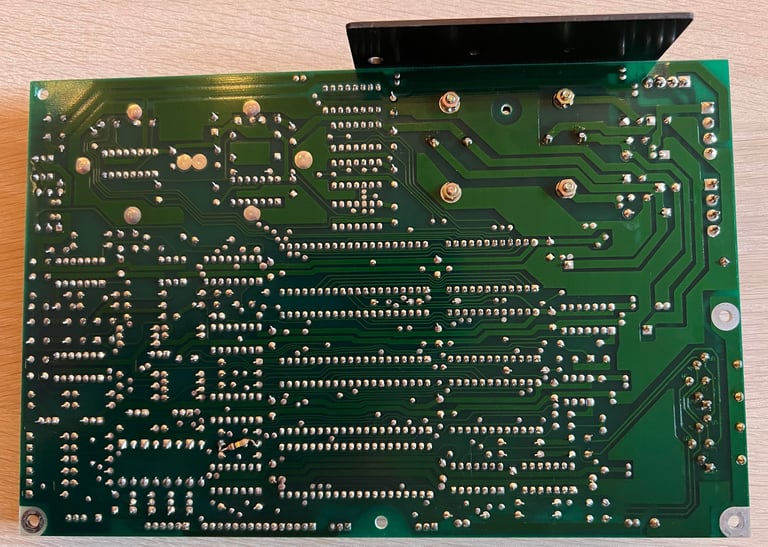
Visual inspection
It looks to me that resistor R44 is soldered... on the backside of the PCB? Why? There is probably a good reason, but I am struggling to see why this is done...
After cleaning the PCB looks in fantastic condition. I am really impressed that a PCB can look this good after nearly 40 years. There are no sign of corrosion and no leaking electrolytic capacitors.
Several of the major ICs are socketed which is normal on the 1541 diskdrive. Below is a table of all the chips installed on this mainboard of this 1541. Based on the date code on the ICs my guess is that this drive was assembled sometime late in 1984 or early 1985.
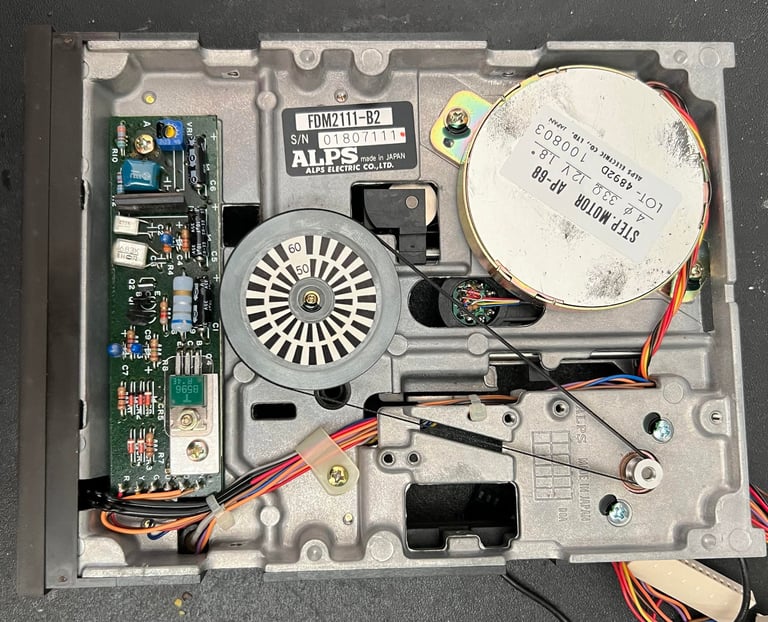
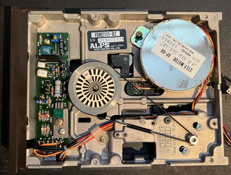
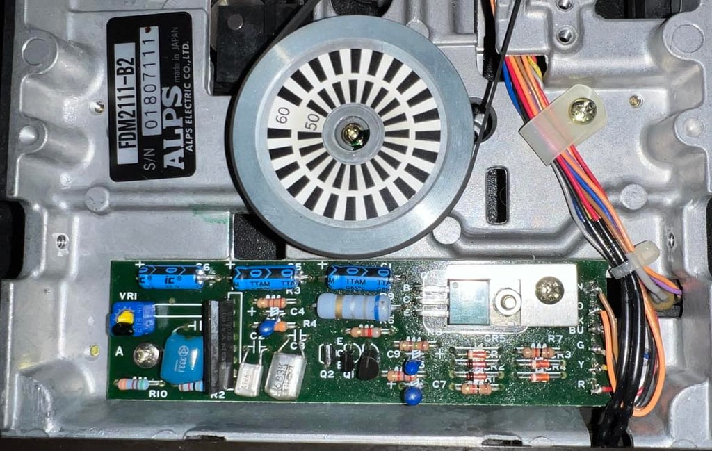
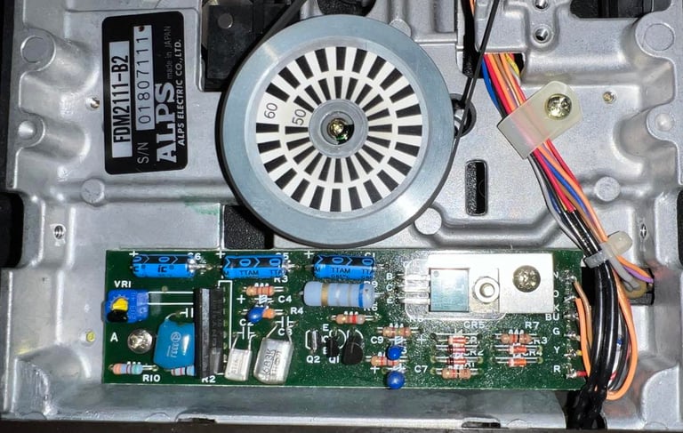
Motor unit
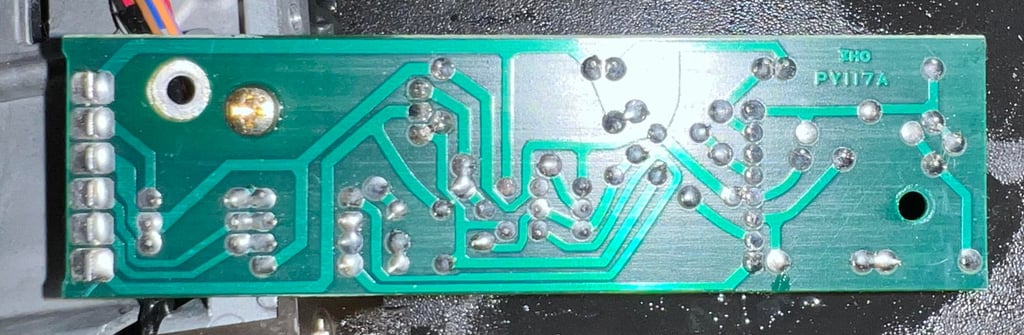
Underneath the disk drive is the second PCB - for the motor unit (PCB version PY117A). The PCB is mounted to the metal chassis with two screws which are removed (yellow squares).
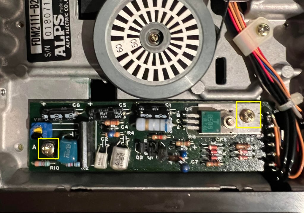
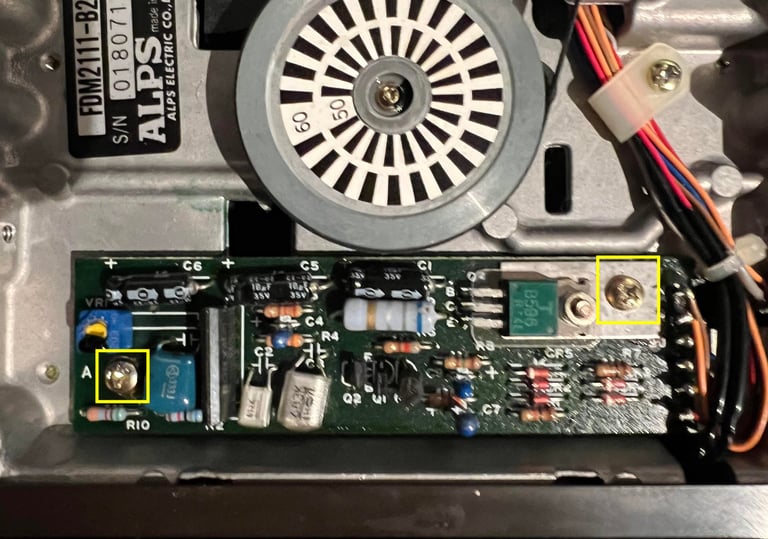
The PCB is full of some sticky "stuff" but seems to be in otherwise good condition. So only to clean the PCB throughly.

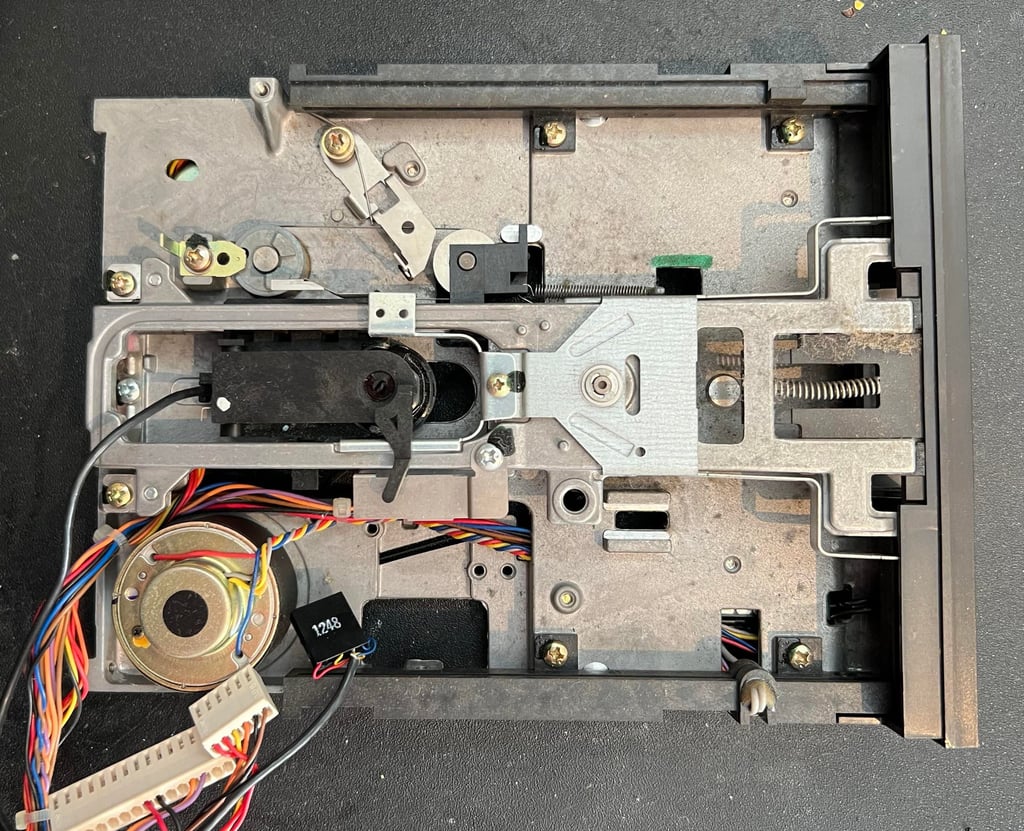
Interior mechanics
Before cleaning the drive itself it needs to be removed from the interior chassis. There are four screws, two on each side, holding the drive in place (blue squares).

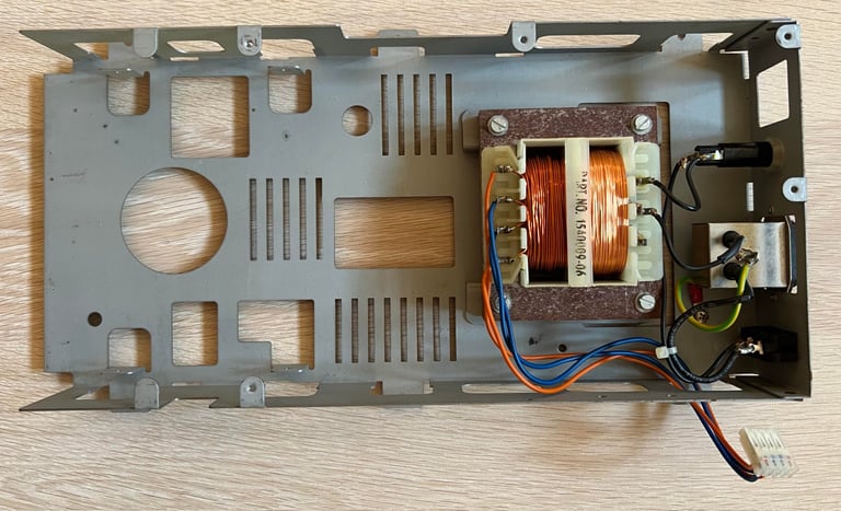
Quite some dust has fallen into the interior chassis, so this is cleaned with isopropanol. Also, the transformer and all wires and connectors looks to be undamaged and without corrosion. Below is a picture of the interior chassis after cleaning.

Cleaning and lubricating the drive mechanism
This is an ALPS diskdrive - see table below for details.
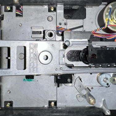
The drive is incredible dirty, but it looks to be intact otherwise.


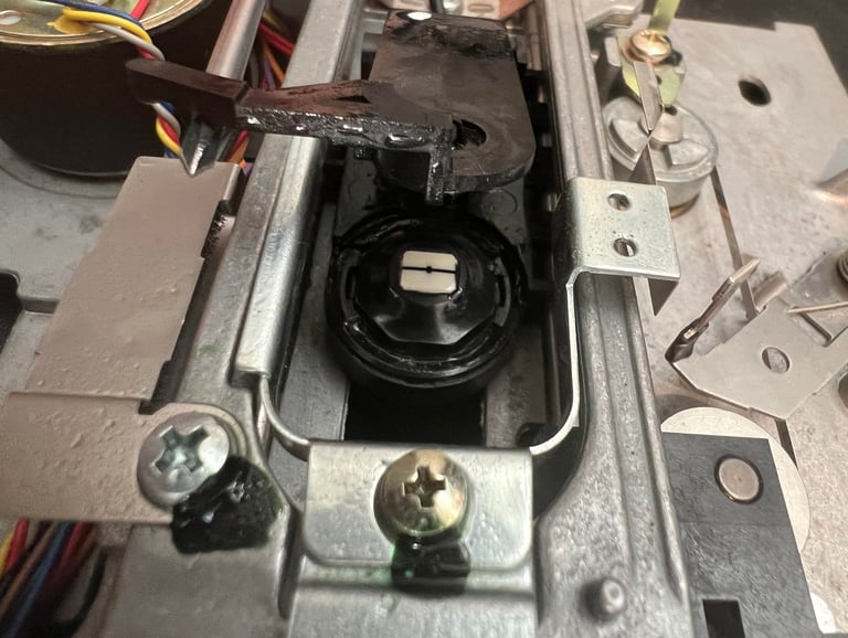
Most of the dust bunnies are removed with some isopropanol and a cotton swab. Then the read/write (R/W) head is carefully cleaned - also this with some isopropanol. It is important not to lift the top part of the R/W mechanism too high. There is a spring here which is not designed to handle great tension. Below is a picture of the cleaned R/W head.
The rails which the R/W head is attached to (and can slide back and forth) are cleaned with isopropanol. And then they are lubricated with some silicon spray (oil).
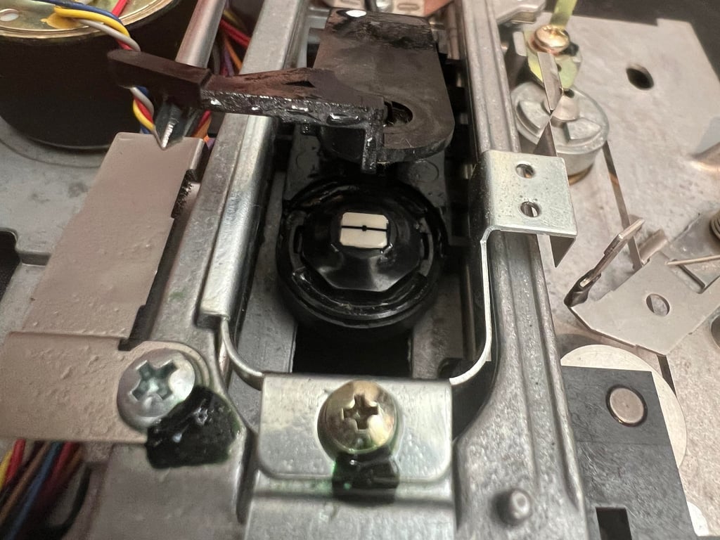
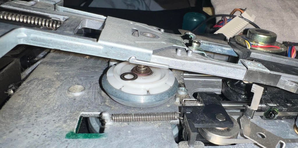
Cleaning the spindle hub mechanism
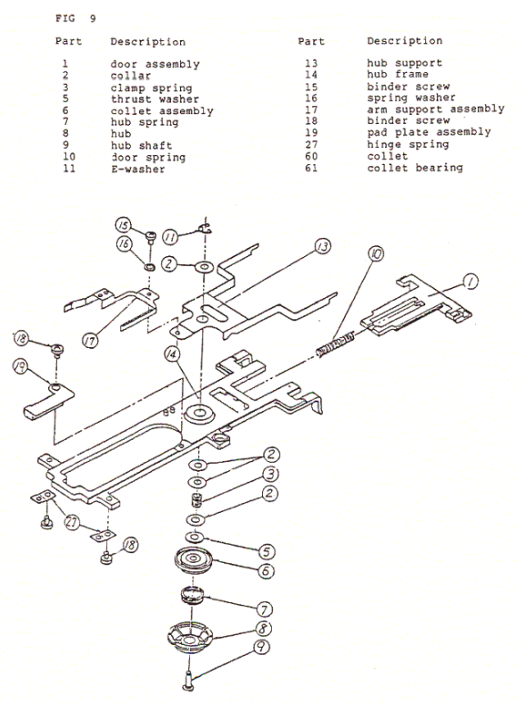
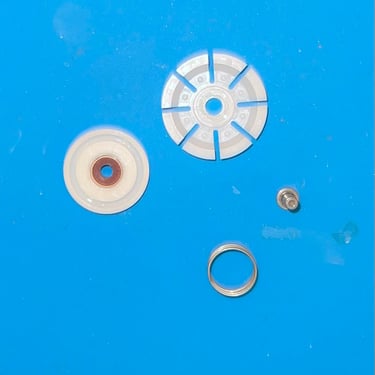
After almost 40 years the spindle hub mechanism can be quite dirty - resulting in a noisy spindle. Also, the floppy can be prevented from rotating freely. So cleaning the spindle hub is required. Unfortunately, the spindle mechanism consists of quite a few parts. In the schematics below an "exploded view" of the spindle hub is shown (click to enlarge).
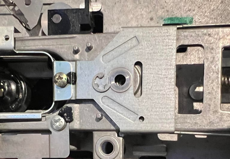

First the e-washer (11) and collar (2) is removed. See picture below.
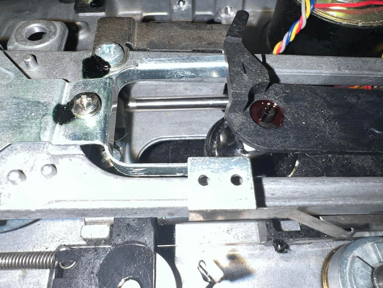
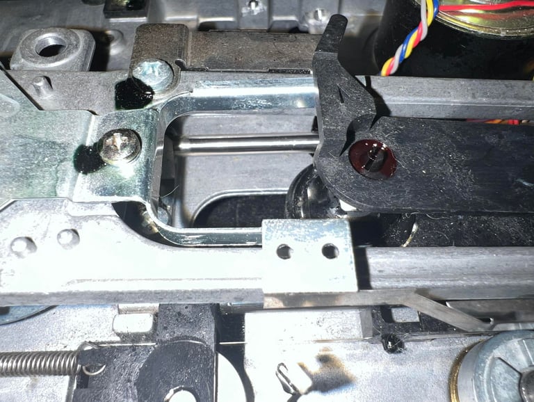
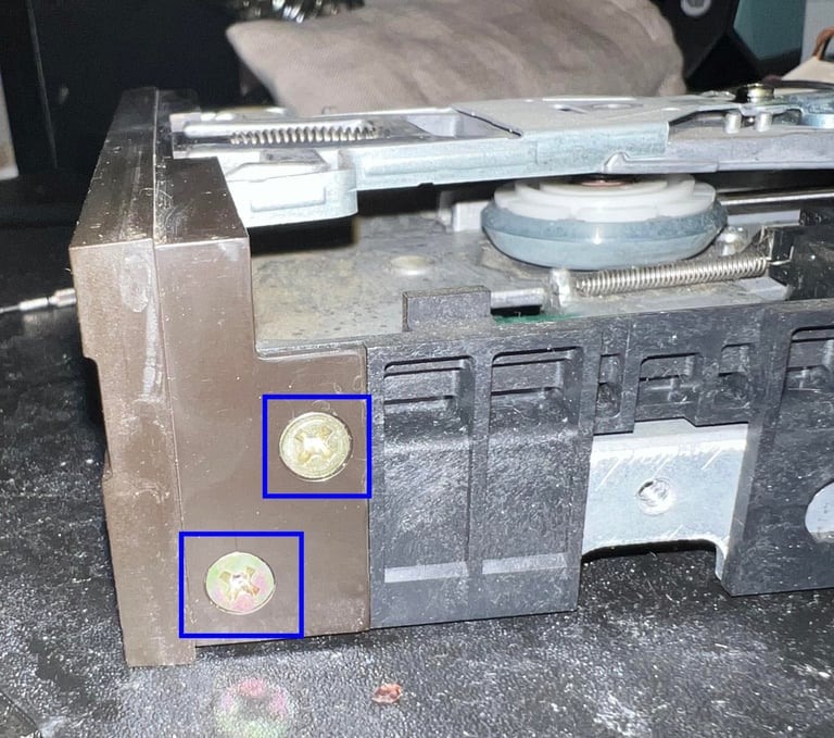
Next the front is partially removed - just enough to lift the "front arms" of the frame under the front - by removing the four screws. See picture below where two of the screws are shown (blue squares).
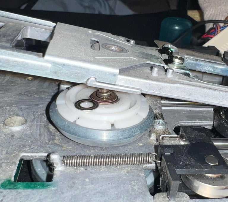
The arm is carefully lifted and the rest of the spindle hub is removed.

All parts are cleaned individually with isopropanol. And the metal shaft of the spindle hub is lubricated. See picture gallery below from the cleaning.
After cleaning the floppy drive is re-assembled - ready for initial testing.
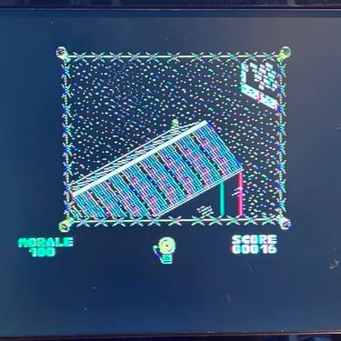
Initial testing
Before the next stage of refurbishing the disk drive is tested. This is to check if the disk drive is in need of:
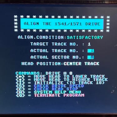
Repair
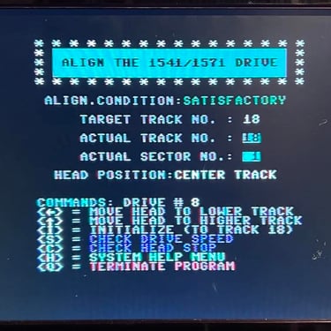
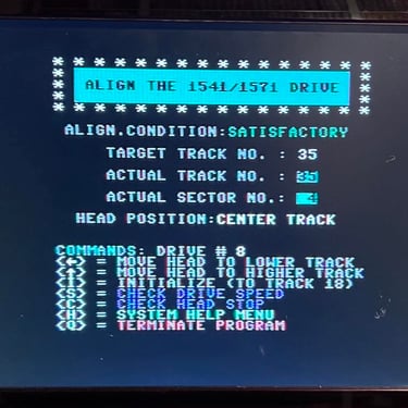
Alignment
Functionality
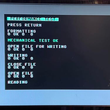
In the table below all the functionality tests are listed. Most of the test are done with the 1541 Test & Diagnostics cartridge (World of Jani). This table will be used as a summary of the initial testing - detailed test results will follow after the table.
Voltages
The 1541 disk drive is supplied by two voltages; 12 VDC and 5 VDC. These are transformed, rectified an regulated inside the drive. In the table below the measured voltages are listed.
Resistances
There are three components in the 1541 which are made up of coils; the R/W head, the stepper motor and the spindle motor. A good indication to see if these work fine is to measure the resistance in the coils - see schematics below.
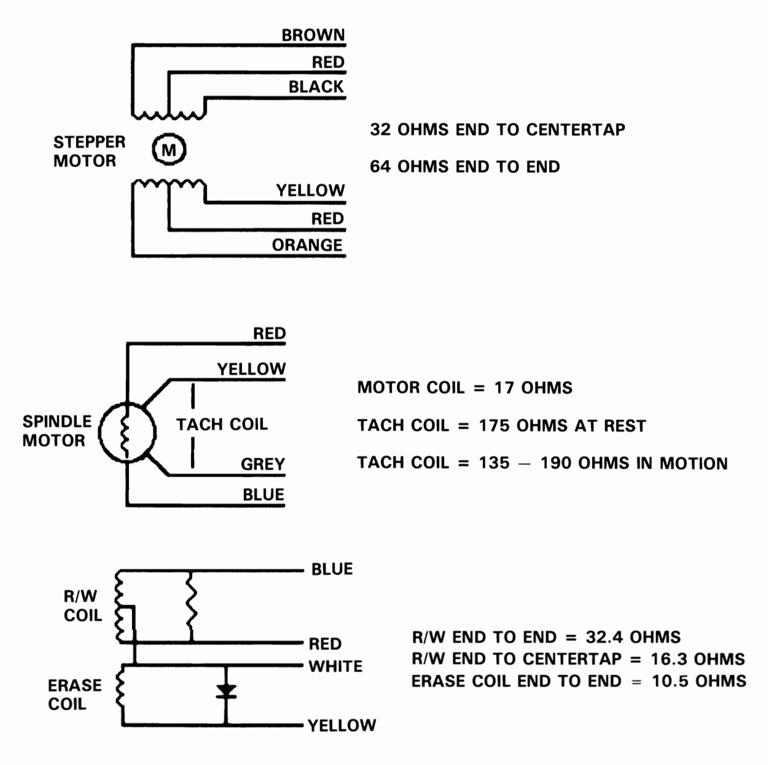

The results are listed in the table below.
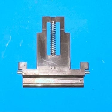
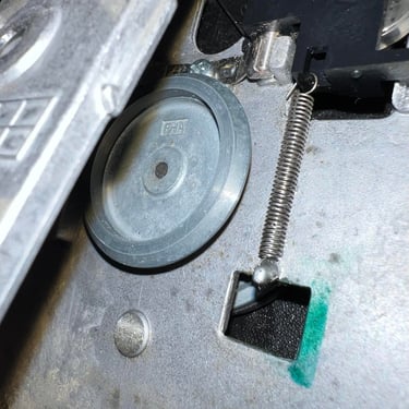
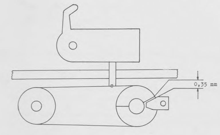
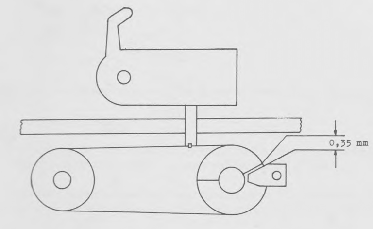
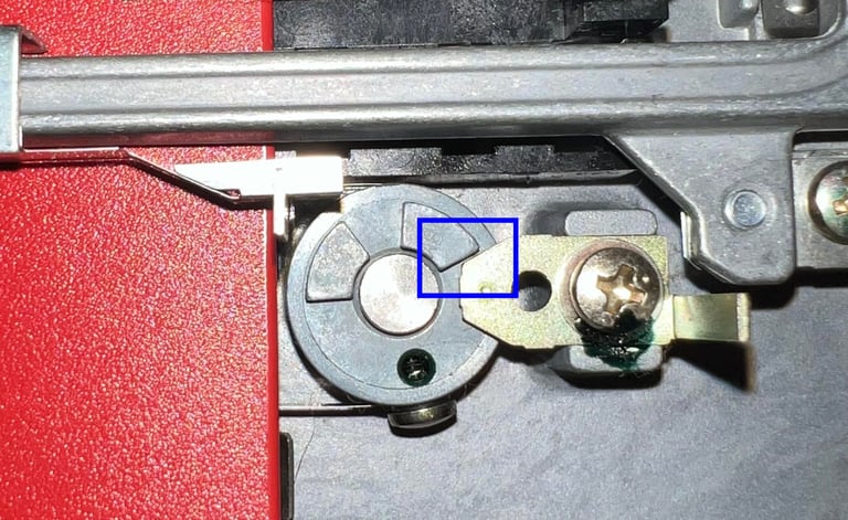
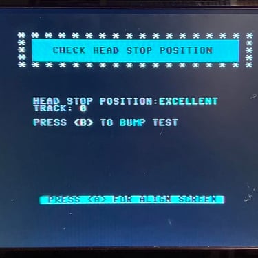
Track 1 stopper
To make sure that the disk is positioned correctly at track #1 the distance between the stop ring and the stopper should be about 0.35 mm. See schematics below.
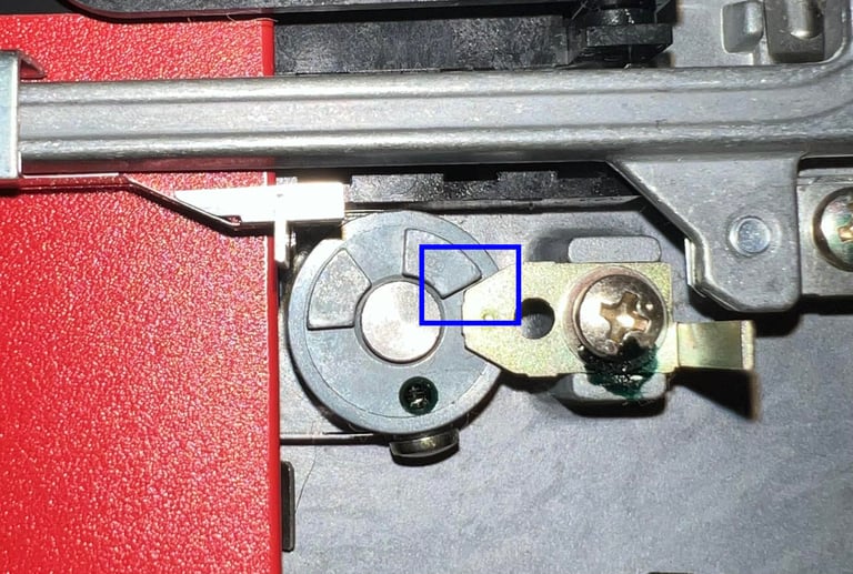
I don not have tools for measuring this unfortunately, but it looks to be around this distance. See picture below.
Conclusion stage #1
The initial testing is by no means an extensive testing. But it looks to me that the drive´s basic functionality is in place so I will continue with stage 2 - replacing old parts.
Pictures and videos from testing
Below are som pictures and videos from the tests described above.


Intermesso
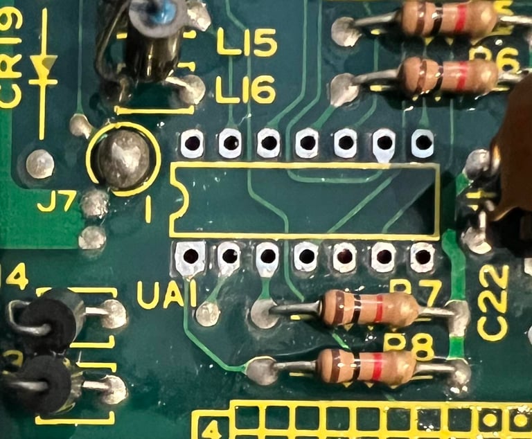
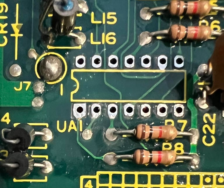
To aid in the repair of another 1541 disk drive I need to borrow the UA1 74LS14 chip for a short period. This chip is desoldered and a new socket is soldered back in. No traces or pads were damaged during desoldering (see picture below). And the best thing is that the other 1541 now seems to work!
STAGE #2:
Replacing old parts
Replacing the drive belt
After almost 40 years the motor belt driving the flywheel is worn out. Much of its flexibility and "grip" is lost and you can experience that the belt just fall out of position. So changing the motor belt is both smart and easy operation. Note; after changing the motor belt it is a good idea to check and adjust the rotational speed of the flywheel (this adjustment is probably required also after the electrolytic capacitors are replaced).
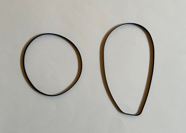
I purchase new belt from Console5. To remove the belt is is just to lift it from the motor shaft and the flywheel - no screws needs removing. In the picture below the position of the belt is shown.

As seen in the picture below the difference between the new (left) and old (right) belt is quite significant. But as mentioned this is not very unusual since this old belt has been (probably) installed in the drive since is was manufactured.
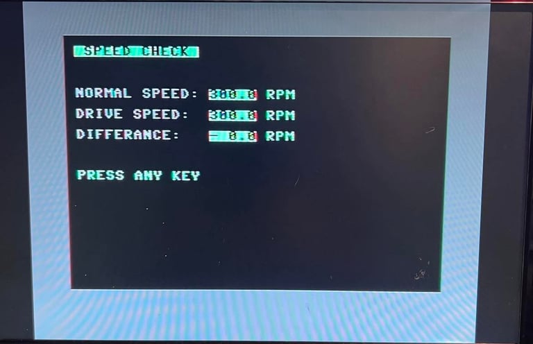
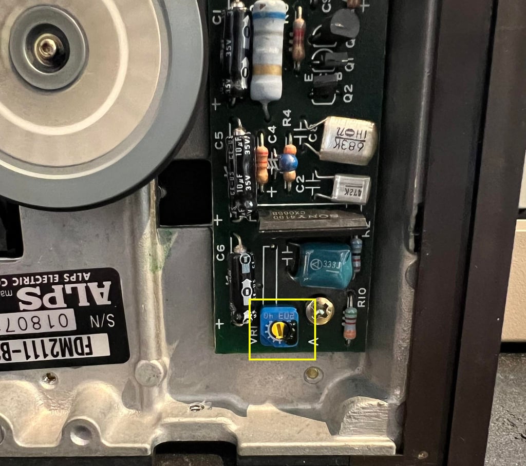
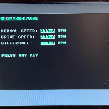
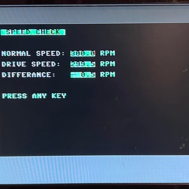
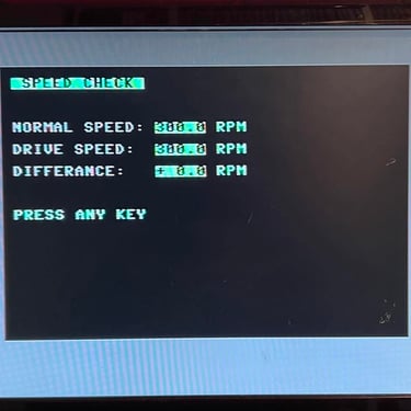
When the new belt is installed a quick check, and adjustment, is done to the rotational speed. To check the rotational speed the 1541 Test & Diagnostics cartridge is used. And while the disk is spinning the VR1 is carefully adjusted with a small flat screwdriver until about 300 RPM is reached. Note that in most of the cases the adjustment is marginal, but it needs to be done to "adapt" to the new belt. Below is a picture of the position of the VR1 potentiometer (yellow square) and also a short video where the new speed is set.


Replacing the electrolytic capacitors (mainboard)
The electrolytic capacitors are prone to dry out due to old age and excessive heat. Although it is not (usually) critical that a electrolytic capacitor dry out for the floppy drive to function I think it is good practice to replace them. Old capacitors with "wrong" ESR value and/or different capacitance than original can give odd behaviour to the drive.
As seen in the capacitor list for this mainboard there are eight electrolytic capacitors. I use only quality capacitors which have a temperature rating of 105 degrees Celcius from Panasonic/Vishay and Wurth Electronics. This is higher than the original capacitors (which have only 85 degrees Celcius for many of the caps) - but there will be significant heat inside the 1541 floppy drive so it is recommended to use a slightly higher temperature rating.
In the picture below the mainboard is shown with the new electrolytic capacitors installed.

The two large capacitors are glued to the PCB - as they were originally from production. This is due to make sure the large capacitors are not damaged by vibration.
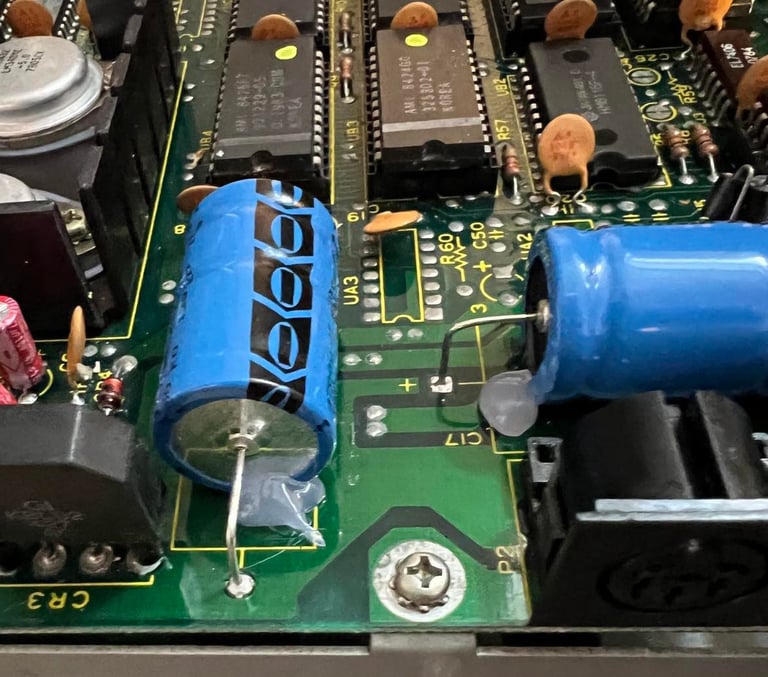
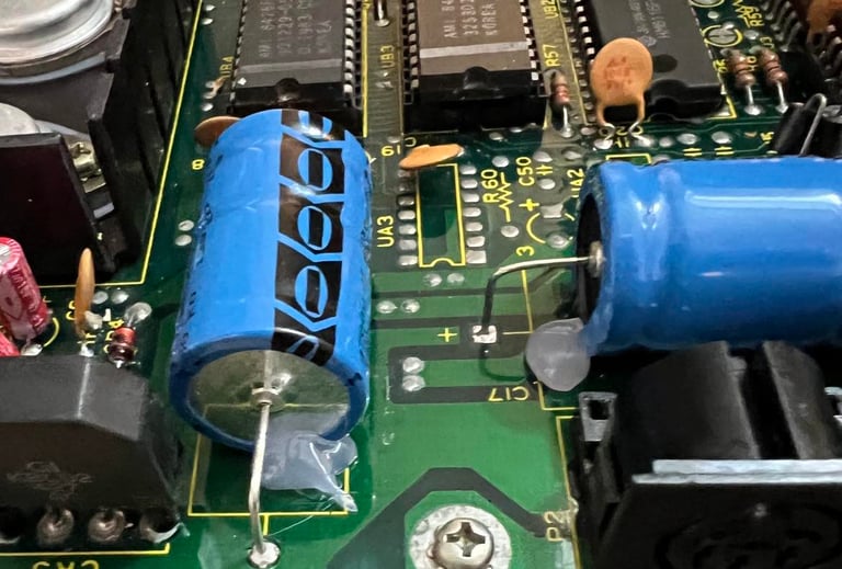
Replacing the electrolytic capacitors (motor unit)
There are only three 10 uF [35 V] axial electrolytic capacitors on the PCB connected to the motor. They are replaced with new quality capacitors from CDE/Illinois capacitors. See picture below.
STAGE #3:
Testing and verification
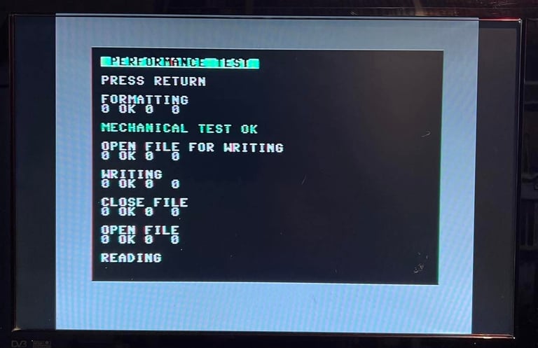
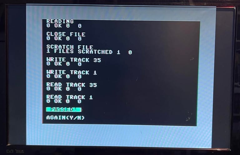
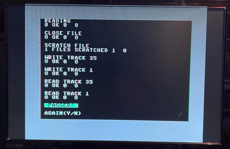
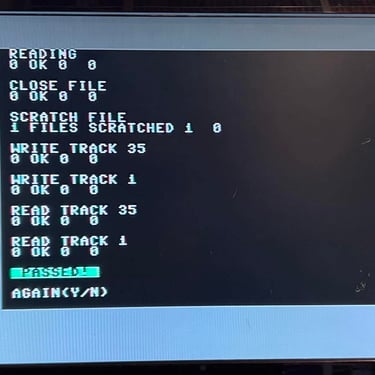
The purpose of this stage is to test, and verify, that the 1541 floppy disk drive works as it should. Basic functionality were tested in stage #1 and now everything is re-tested and verified. A combination of software tools are used in this process - please see description of tools.
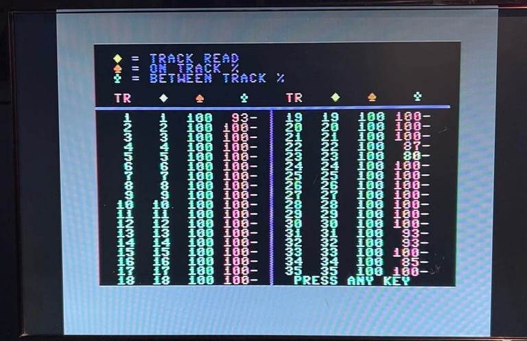
In the table below are the results and at the bottom some images from the testing are shown.
All test pass without any issues so the drive works as it should as far as I can see. In the gallery below are some pictures from the testing (click to enlarge).


Final result
"A picture worth a thousand words"
Below is a collection of the final result from the refurbishment of this 1541 floppy drive. Hope you like it! Click to enlarge!


Banner picture credits: Medvedev