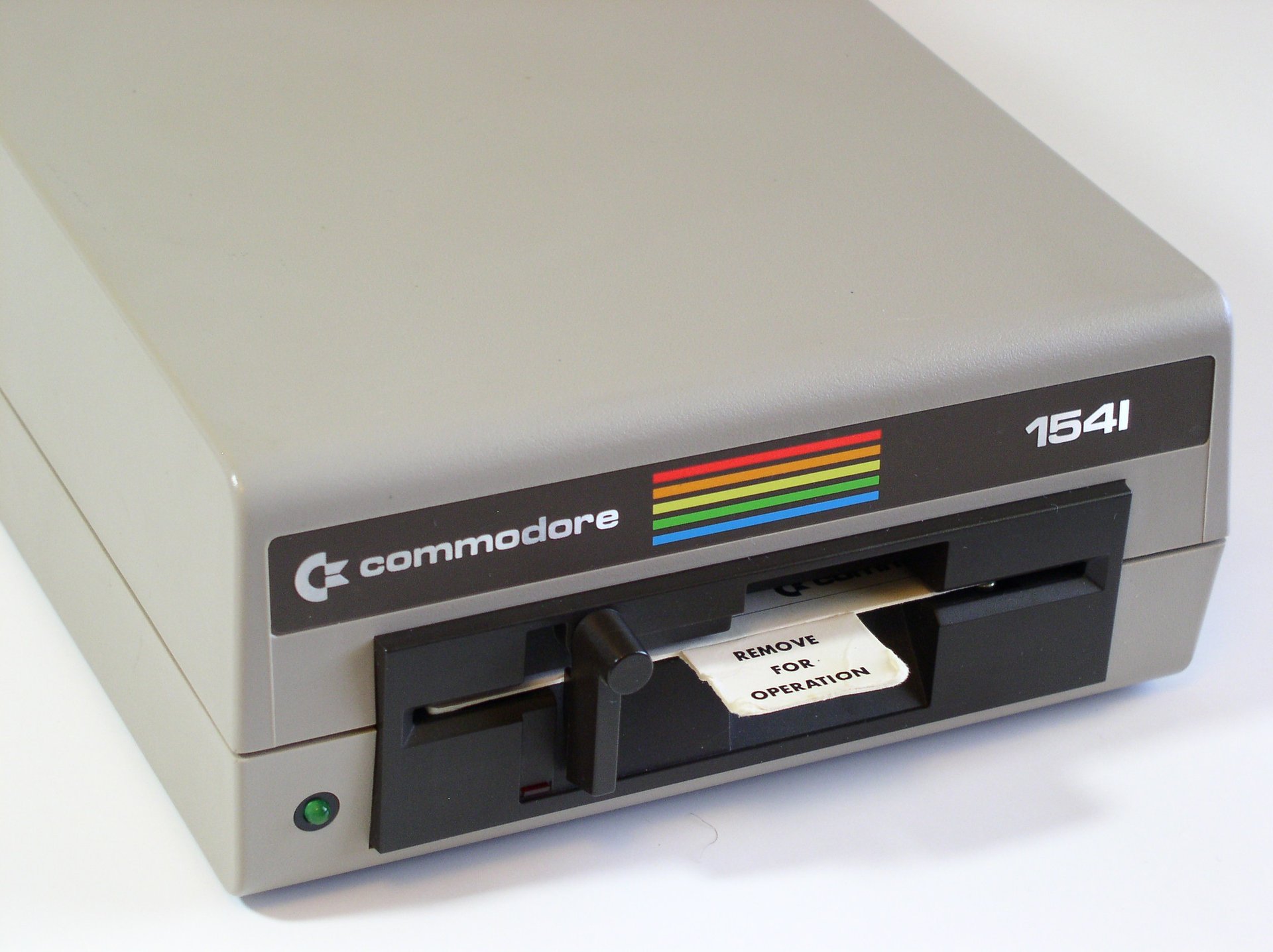
Commodore 1541
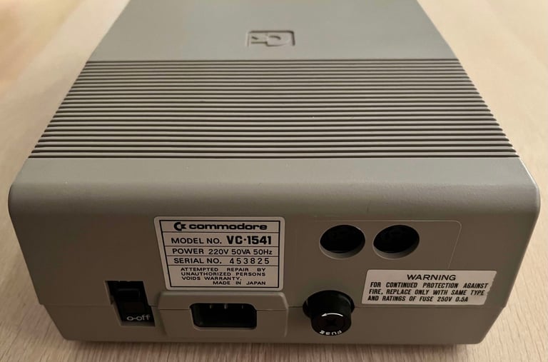
Ser. No. 453825
PCB No 1540050 (REV C)
MDK 25 HB
ALPS-Drive
Starting point
This Commodore 1541 floppy drive is in for some refurbishment. The floppy drive is part of a bundle of two drives, where the owner has previously informed be that both of them have various problems of reading. The idea is to try to use both of the drives as a source for parts to make one drive functioning. But we´ll see as we go along where this floppy drive takes. Old computer gear always give surprises - either good ones or bad ones.
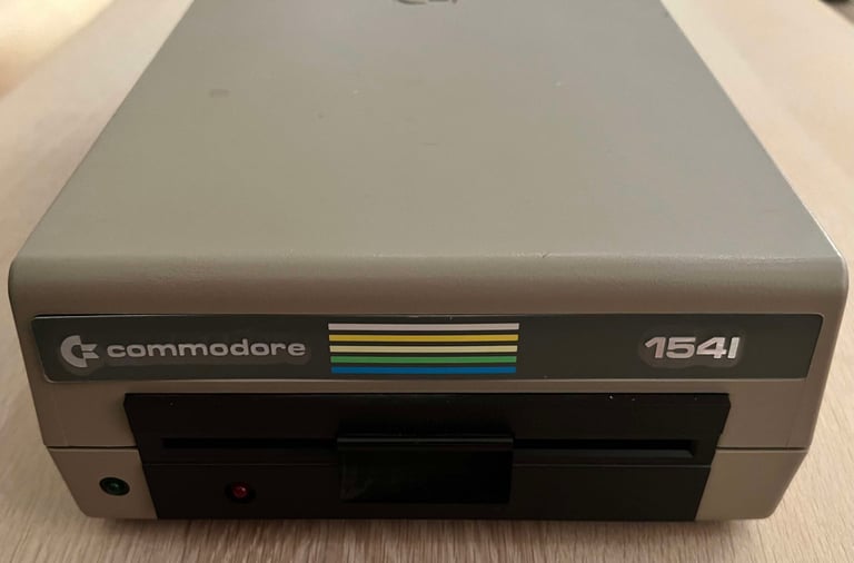
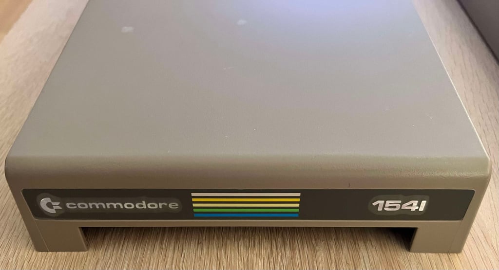
From the outside the floppy drive looks to be in very good condition. There are some signs of use (and some dirt), but this is what to be expected after 35+ years of age. The front of the drive reveals that this is (most probably) an ALPS drive. This is a good sign. Compared to Newtronics drives the ALPS drives are more likely to have a working R/W head.
The front badge is partly loose, but it does seem to be undamaged as far as I can see. Only thing is that the metal is slightly bent, but that should be fixable. And... how cool is this... the plastic film covering the badge appear to be still on! I will leave it to the owner to decide if it should be removed or not. The yellowing is not bad at all, but I still think that it would benefit from some retrobrighting as part of the refurbishment.
But there is something which concern me a bit: there is a small rattling sound inside the floppy drive. Something is loose inside. It does not sound too serious, but it needs to be investigated.
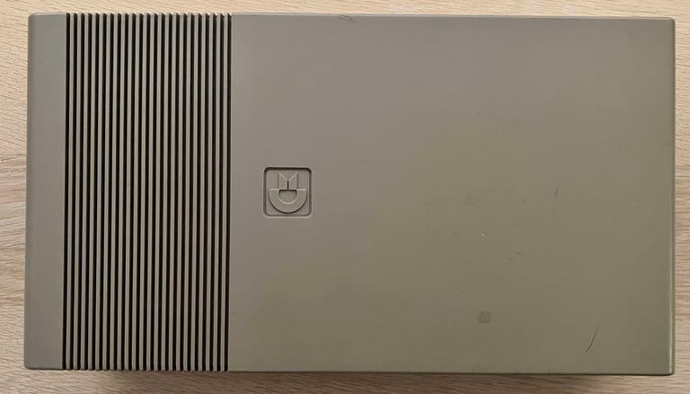
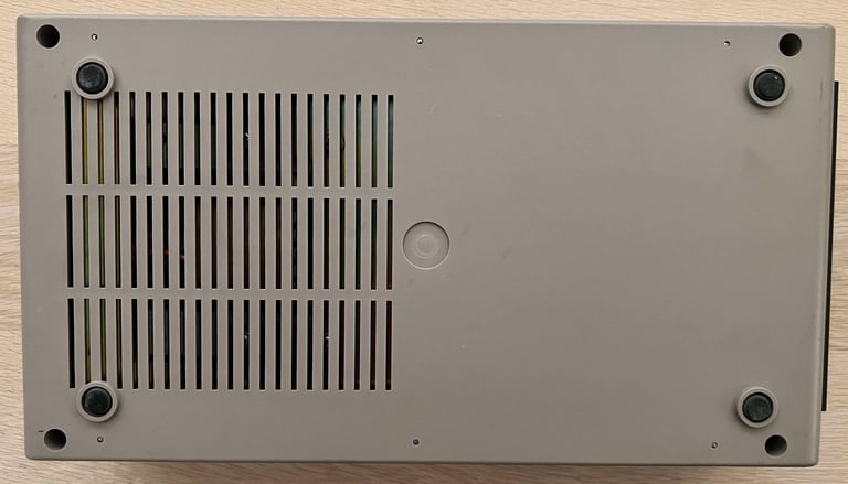
Below are some pictures of the 1541 floppy drive before refurbishment.





Refurbishment plan
WARNING: Refurbishing a 1541 will require working on a device connected to live power (230 V / 110). Danger! Risk of electrocution!
To refurbish this 1541 disk drive the plan is to do this trough the following actions (some of them in parallell and different order). Actions in square brackets are performed if required.
STAGE #1: Cleaning, inspection and repairing
- Clean and (retrobright) the exterior casing
- Clean and inspect the PCBs (mainboard and motor unit)
- Clean the interior and lubricate moving parts
- Initial testing
- [Repair mainboard]
- [Replace drive belt]
STAGE #2: Replacing old parts
- Replace electrolytic capacitors (PCB-spindle motor unit)
- Replace electrolytic capacitors (PCB-mainboard)
STAGE #3: Testing
- Verify drive operation by testing the drive with normal Commodore 64 usage


STAGE #1:
Cleaning and inspection
Disassembly
To start disassembling the 1541 floppy drive the four Phillips 3 x 10 mm machine screws are removed.
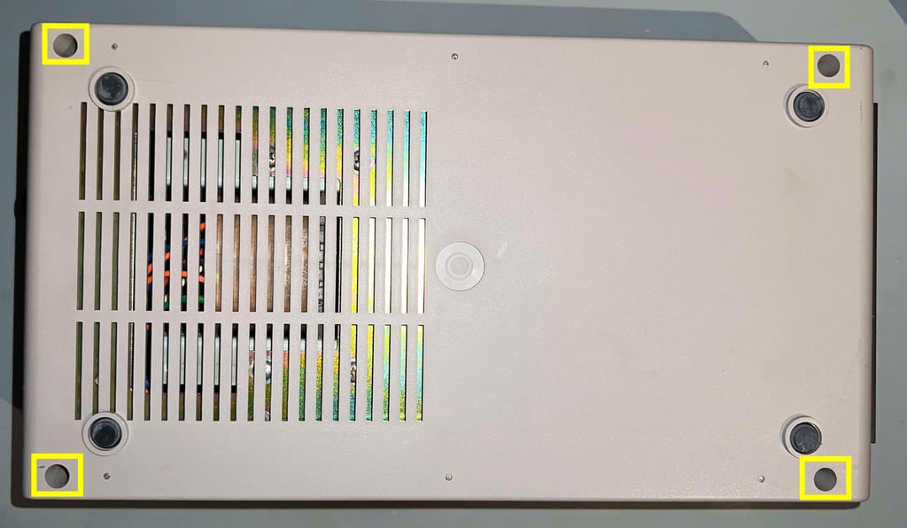

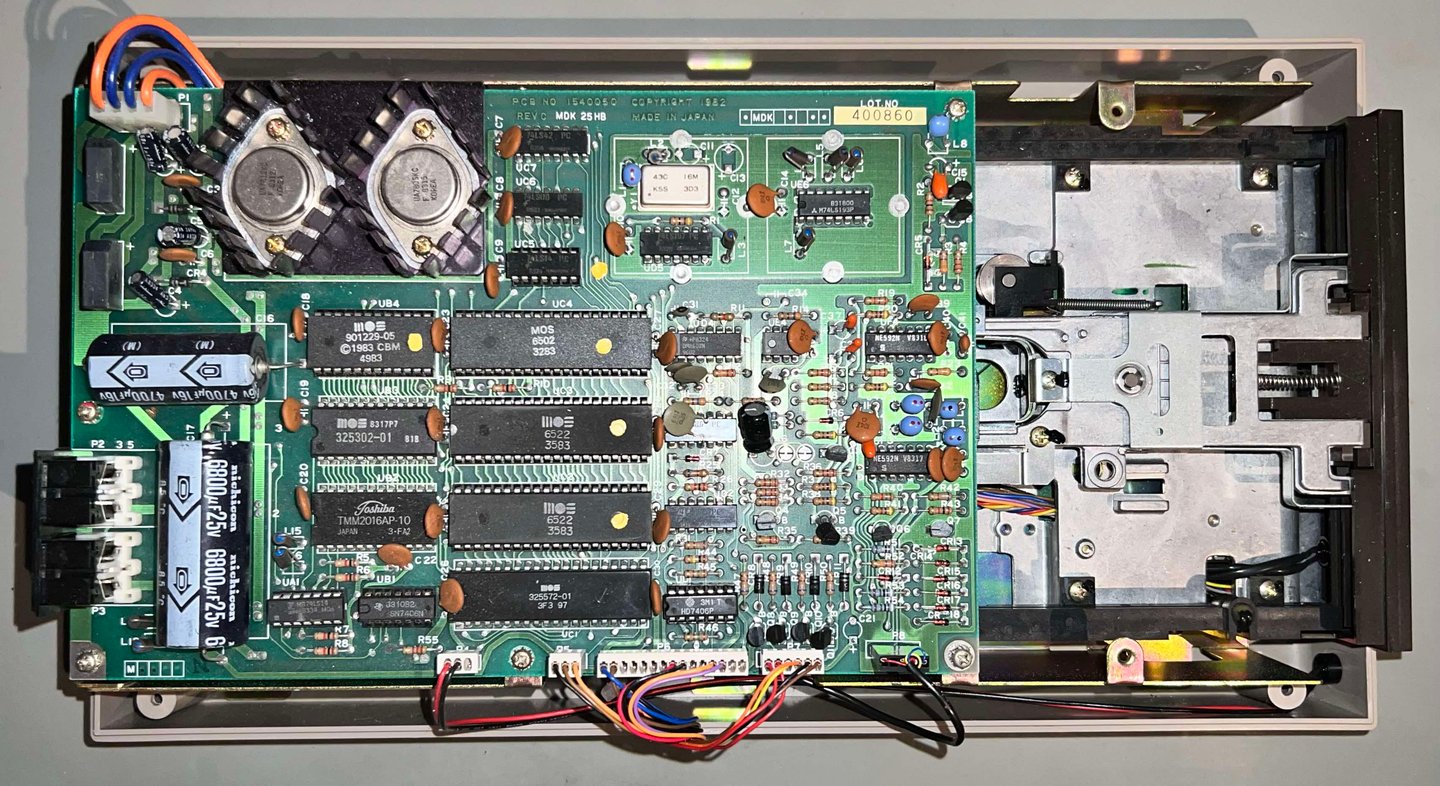
With the four screws out of the way, the top cover is lifted away. The PCB, and parts of interior mechanics, are now revealed. There are some sign of dust and grease in here. I immediately notice that this floppy drive have probably been repaired earlier since a few of the glue logic ICs are in socket.

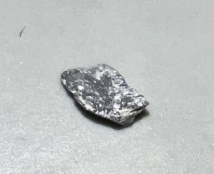
Remember the rattling sound? I don´t see anything immediately. No loose metal- or plastic parts laying around. But when I turn the floppy drive upside down, something falls out... which is a... eh? stone? See picture below and decide for yourself. Ok, not a huge rock, but a small 2 mm piece of something...

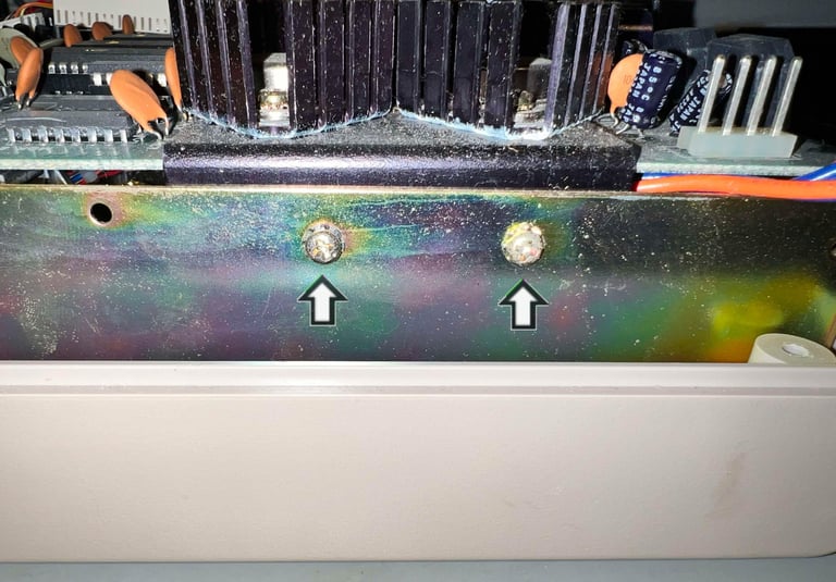
To remove the PCB from the drive mechanism seven screws needs to removed (3 x 6 mm Phillips). Note that there is a toothed lock washer on each of the screw. This is to secure that the PCB does not move while the floppy drives operates (the vibrations in a 1514 floppy drive are significant). There are five screws at the top side of the PCB and two screws mounting the voltage regulator heatsink at the side.
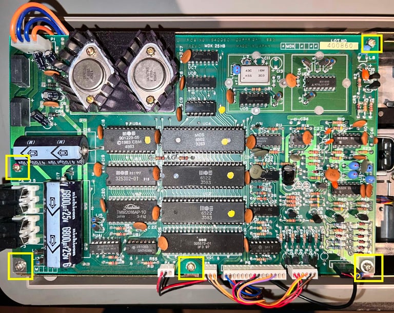


Before the PCB can be lifted, the six connectors need to be detached. WARNING: It is good practice to make a note on how these are connected. If these are connected in the wrong orientation, you are running a big risk damaging the R/W head, motor unit controller and the mainboard itself.
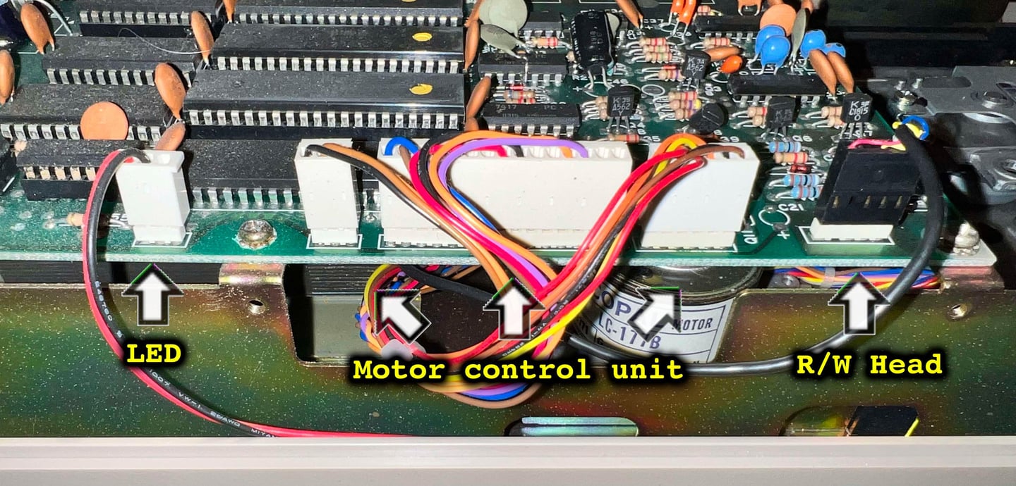

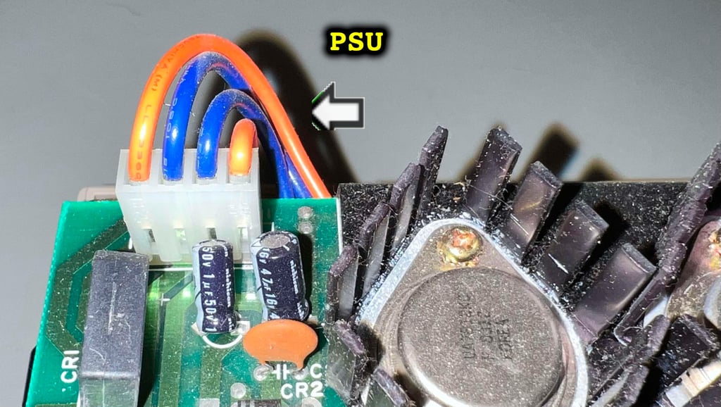

When the PCB is lifted away, the interior mechanics are revealed. And it looks very - VERY - good! I can not see any immediate signs of corrosion, and there is very little dust. There are some dust and grease, but it is really marginal.
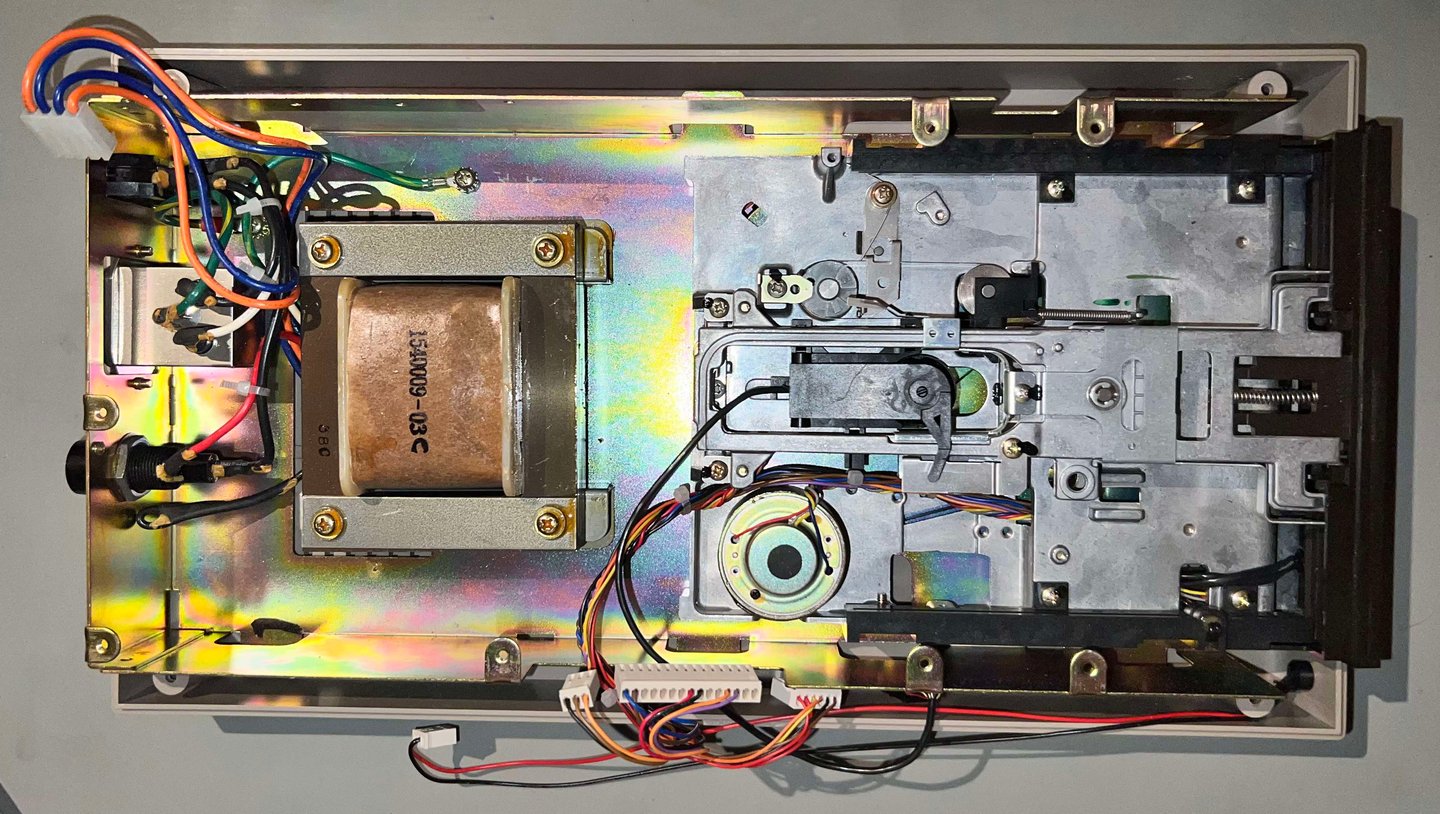

Nearly there. The large interior metal tray holding the drive mechanics is fastened to the bottom cover with six 3 x 10 mm Philips sheet metal screws.


The interior tray is lifted away from the bottom cover and the cover is revealed. Also here, there is very little dust and grease.
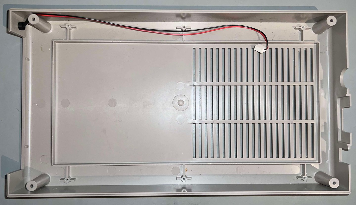

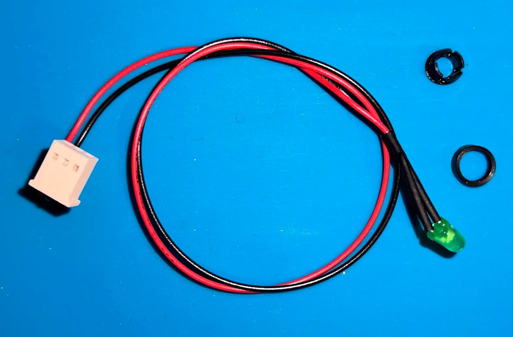
The LED is removed from the bottom cover. This is done in three simple steps:
The inner plastic ring is loosened
With a firm push the LED is pressed from the outside towards the interior until it pops out from the LED bracket
The LED bracket is pushed firmly from the inside towards the outside until it pops ut
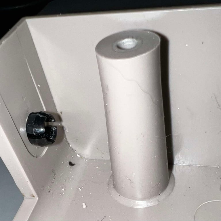
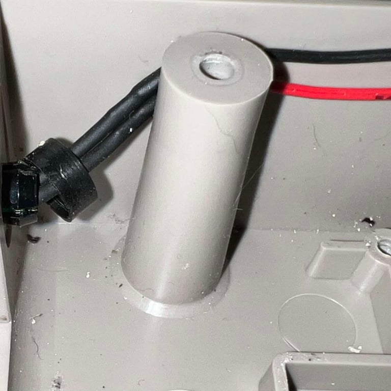

The last stage of the disassembly is to remove the floppy drive mechanism from the inner bottom tray. The floppy drive is held to the metal frame with four 3.5 x 9.5 mm Phillips machine screws (two on each side).

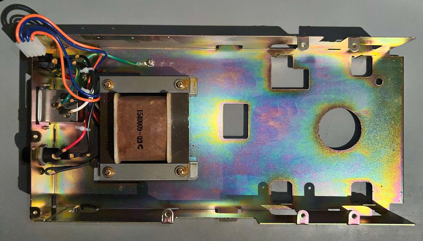
As with the bottom cover, the inner metal shield is in fine condition. No signs of rust, and hardly any dust and grease. Also the transformer seems to be in good visual condition.

Exterior casing
"It´s time to take a bath!". The covers are not at all bad looking, but they would benefit from a good cleaning. So the covers are placed in mild soap water for about 24 hours.
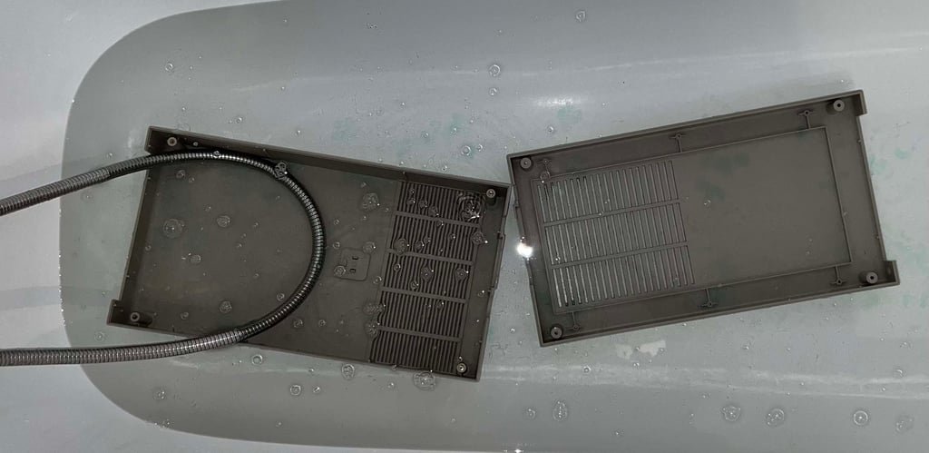

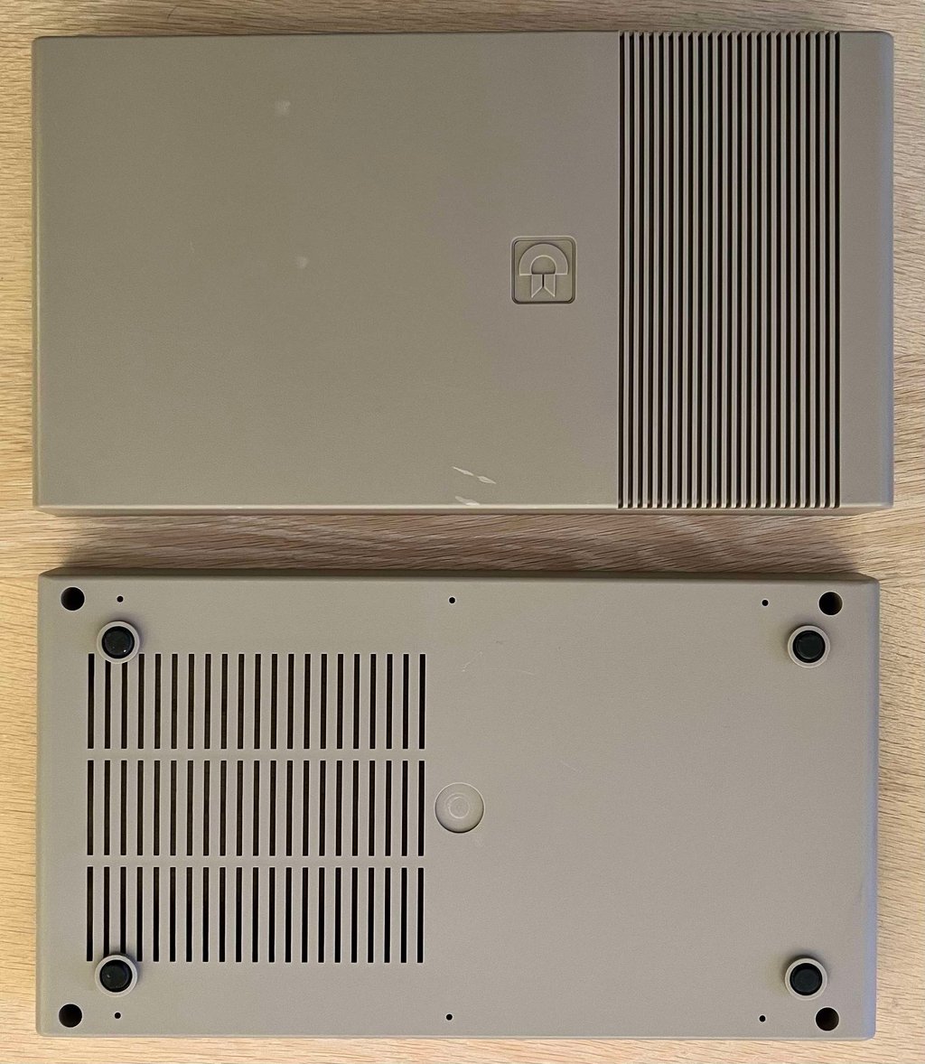
After the long bath the covers are wiped with some isopropanol which removes the toughest dirt spots. The covers looks very nice after cleaning. NOTE: Signs of use, such a small cable burn mark and some lighter areas, are more visible after cleaning. These were previously covered by dust and grease. But they are not very visible in normal daylight, but here are the nonetheless. I am not entirely sure how much effect a retrobright will make, but I think I will do that anyway. Below are some pictures of the covers after proper cleaning - but before retrobrighting.
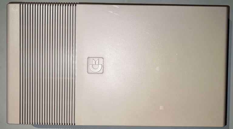

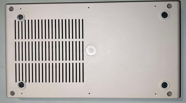

A trained eye might notice that the four rubber feet at the bottom cover are removed (by using a thin flat screwdriver). The reason for this is that these rubber feet will get like "meltet glue" from the retrobrighting process if they are not removed. Also, before the retrobrighting the metal badge is removed. This is not stritcly required, but since I will try to flatten the metal badge, and install some double sided tape at the back, it is easier to remove it. By using some hot air from a hair dryer, and some prying tools, the badge come off quite easily.
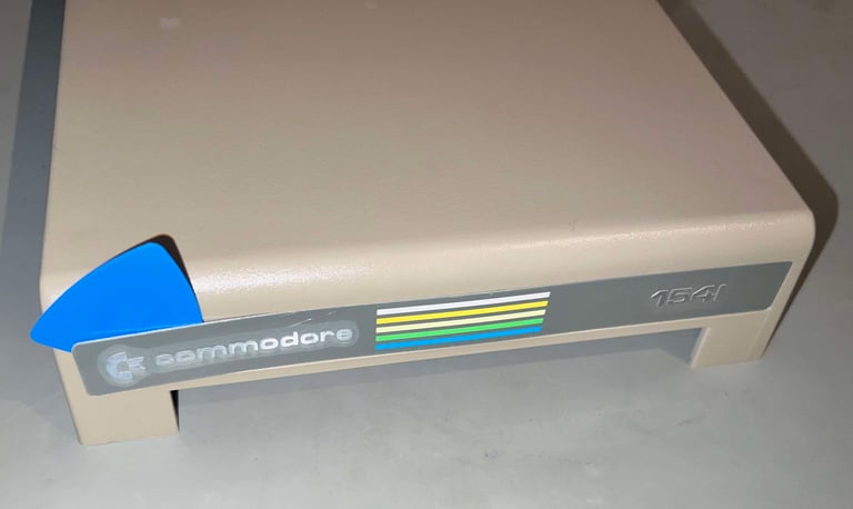

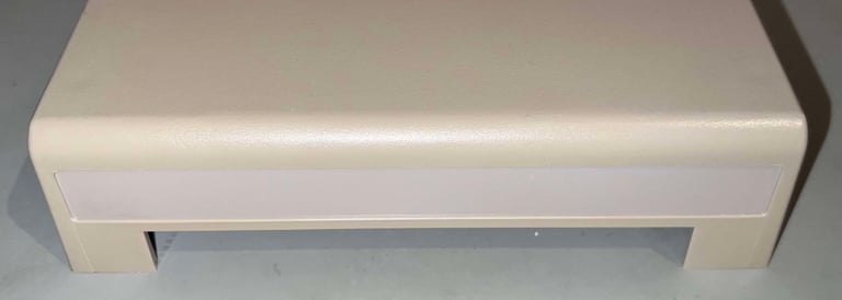

After cleaning the badge it becomes obvious that the plastic film is still on! That is very cool after 40 years! But I will leave to the owner to peel it off.


The top- and bottom covers are retrobrighted for about 12 hours. The processes is based on applying 12 % hydrogen peroxide cream regularly to the covers. To make sure that the cream doesn´t dry out while they are exposed to the UV light, the covers are wrapped in cling film.
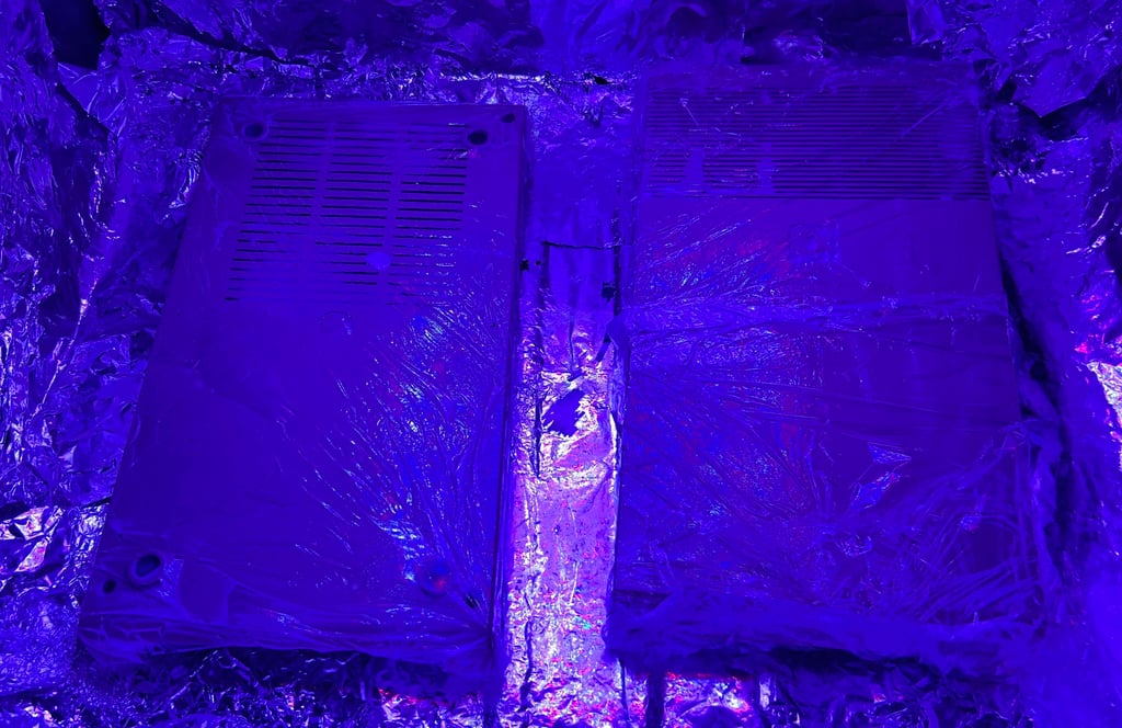

After cleaning and retrobrigting the covers look way better. Even if they were not very yellowed the look "fresher" now. Note that on downside the small marks from usage is now a bit more apparent.


PCBs - Inspection and cleaning
There are two PCBs in the 1541:
Mainboard with most of the logic
A smaller PCB used to control the speed of the spindle motor
Visual inspection (mainboard)
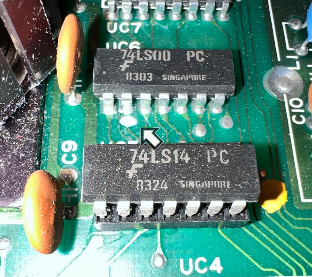
This is a PCB No. 1540050 (Rev C) / MDK 25 HB mainboard. All the ICs are present, and there are no obvious signs of leakage from the electrolytic capacitors. But there are two things which needs investigation:
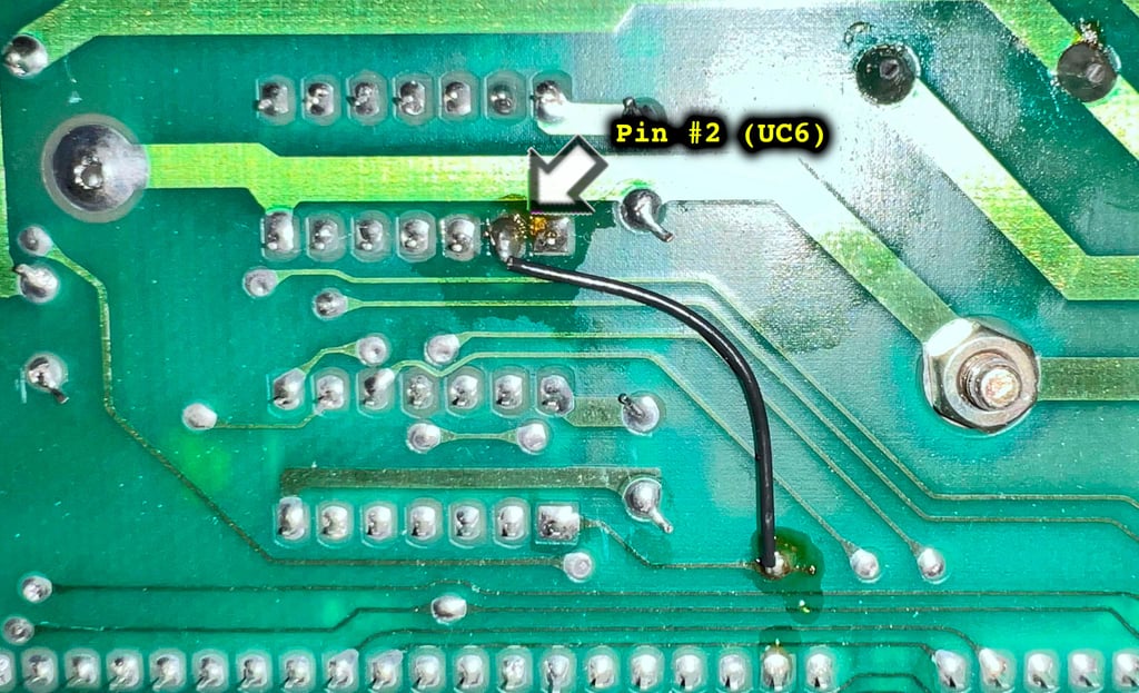
Just next to pin #2 of UC6 (74LS00) there seems to be a small pitch of corrosion (?). I am not really sure what this is, and what caused it, but it does look like one or two traces surrounding UC6 are broken. But could this be intentional? That a small hole has been drilled at factory time? By reading the next to bullet points you can see why ask this question.
Four of the glue logic ICs are in sockets (UA1, UB1, UC5, UD1). At first I thought that this was due to a previous repair, but I am not so sure any more. At the back of the PCB there are not much signs of repair work. Of course, the repair could have been done very professional, but you often see some signs of rework which I do not see.
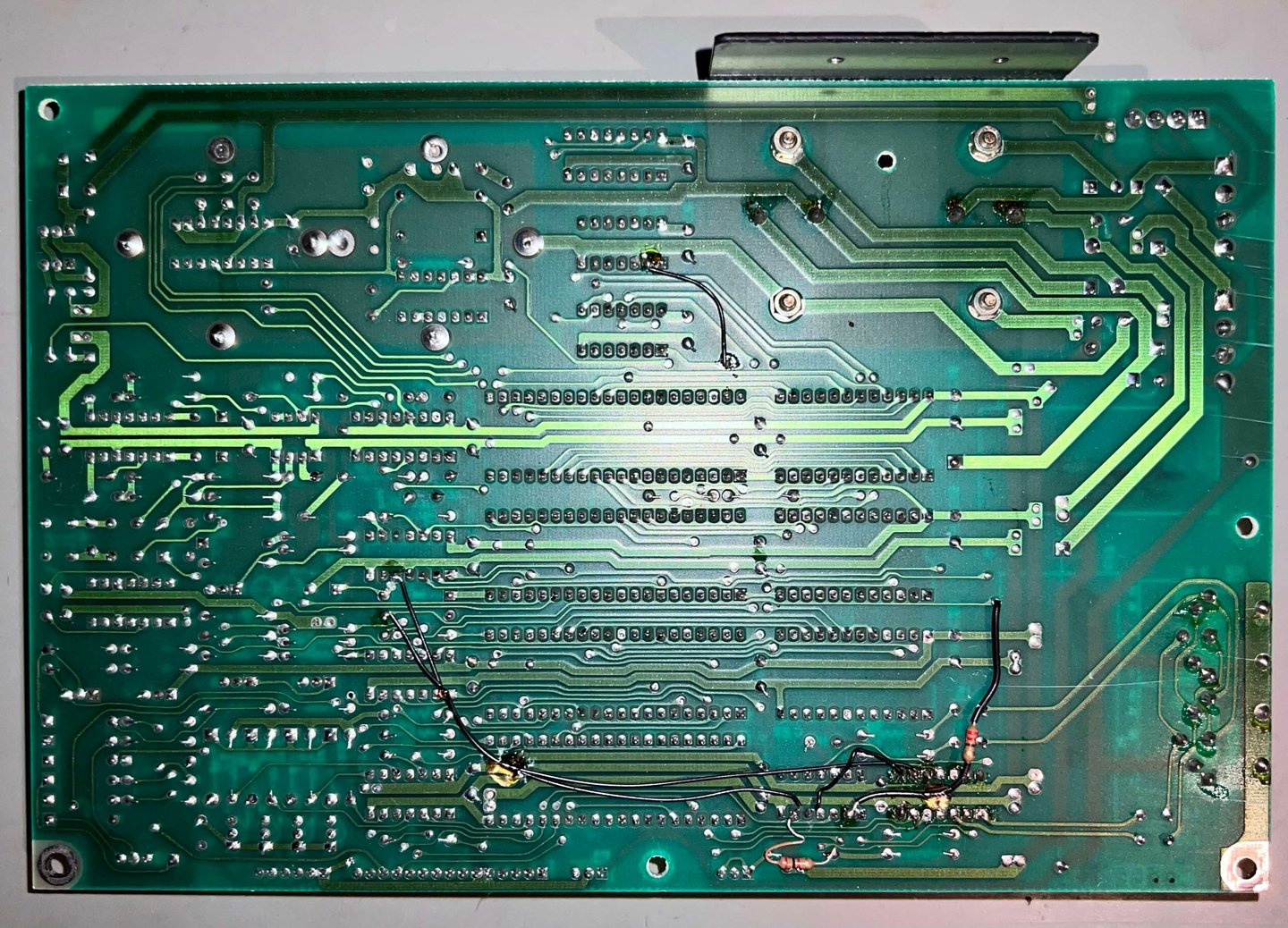
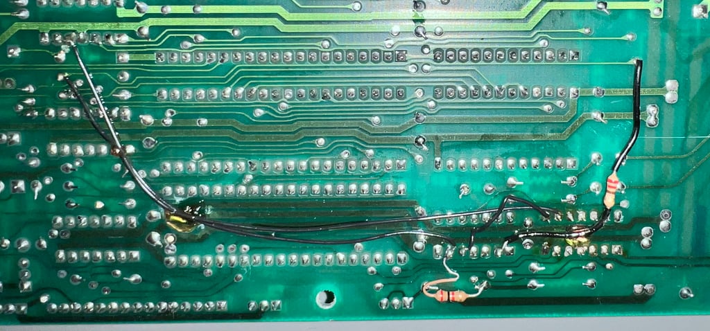
On the bottom of the PCB there are some bodge wires. Even if this might not look very professional I think that this might be from factory. Mistakes in the PCB design could easily have been corrected this way. NOTE: some of the bodge wires are connected to UA1 and UB1. So you could argue that this is actually re-work from a repair, but the solder points on these ICs does not give away any of such signs...
Below are some pictures of the mainboard before refurbishment.
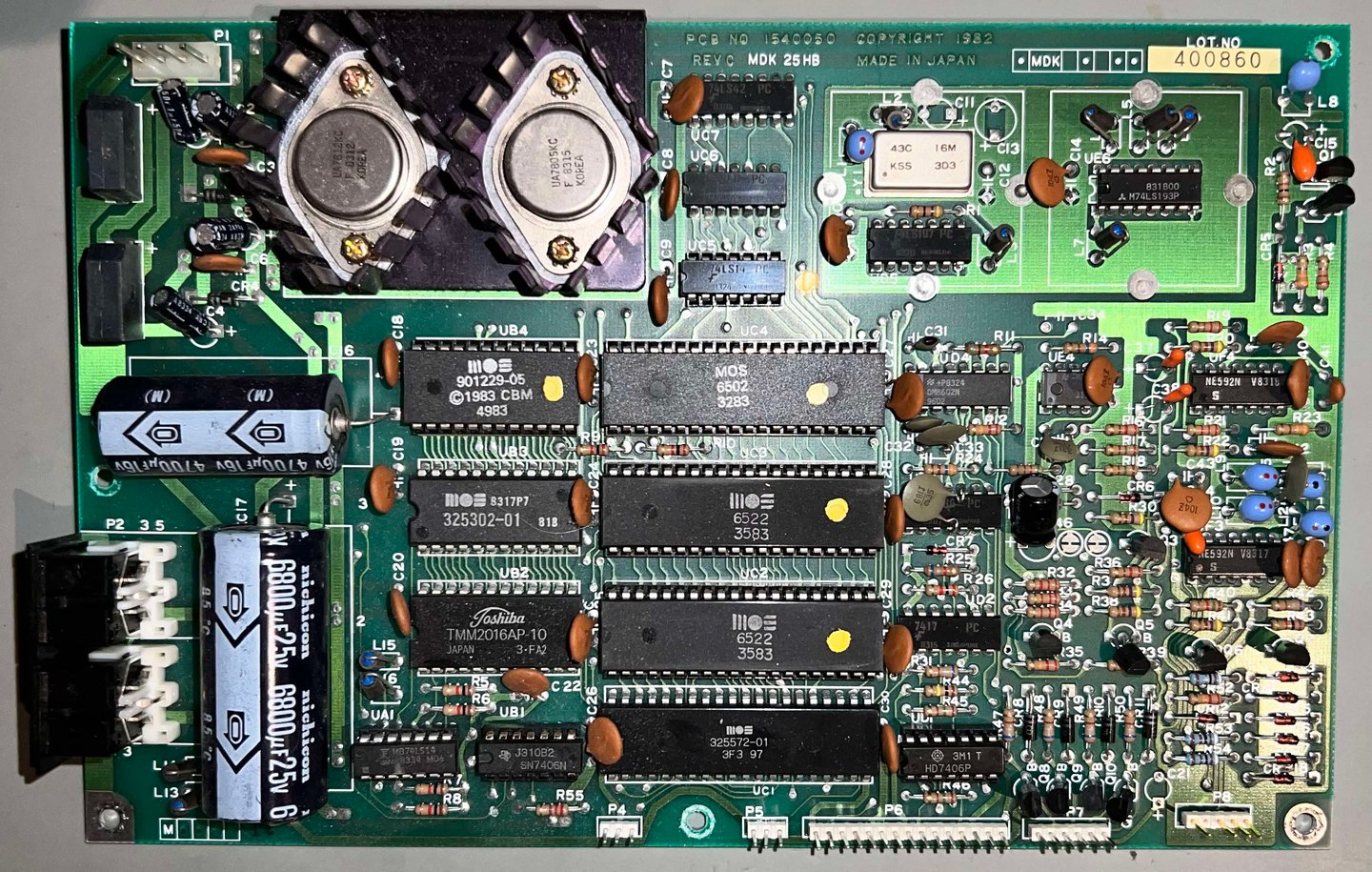


A close-up picture of the cut/broken trace area around pin #2 (U6) below. I am starting to think that this is intentional, but I am not sure if this is done at factory or related to a later modification.

The reason why I start thinking that this broken/cut trace is intentional is that one of the bodge wires are directly soldered to pin #2 (UC2). See pictures below. Also, below is a close-up of the rest of the modification. Unless the drive fails during the initial testing I will leave it like this - assuming this is a fabric modification.


In the table below is a list of all the main chips installed on the mainboard. Note that it is normal that several of the chips were socketed at production time - so this is not a sign of rework.
Visual inspection (Spindle motor speed control unit)
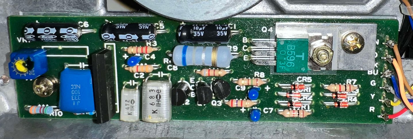
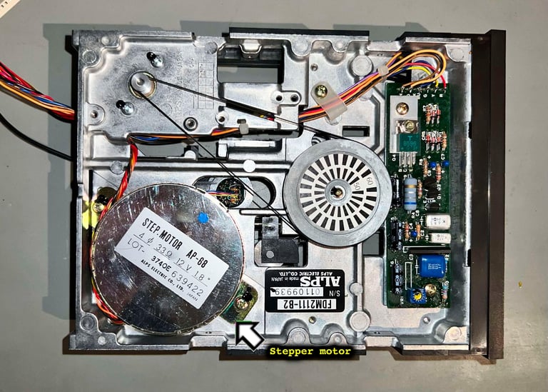
The motor speed control PCB is found on the underside of the floppy drive together with the flywheel and drive belt. This is a PY117 revision of the PCB which is quite common. The PCB looks to be in good condition - it is somwhat sticky and dirty, but I can not see any sign of corrosion or damage.


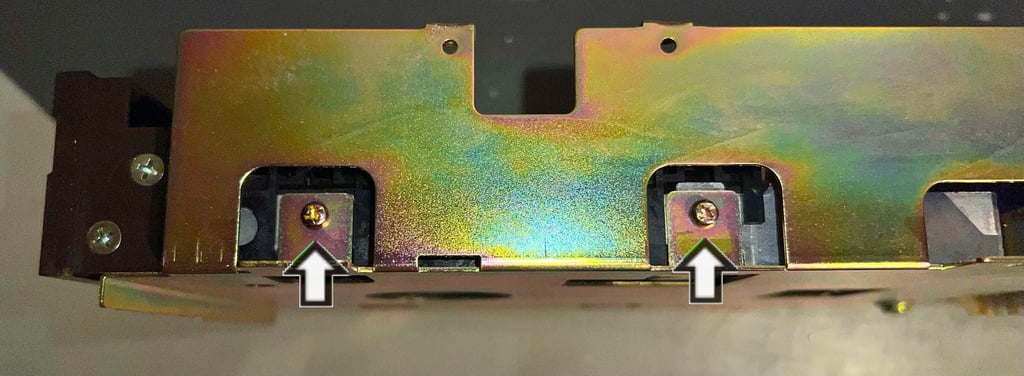
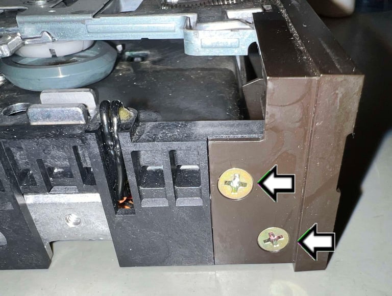
There are two screws holding the motor unit PCB to the chassis (see arrows in picture above). These two are removed and then the PCB is lifted out from the drive. As seen from the picture below, this PCB is full of sticky flux residue. This is not a real problem, but it is good practice to clean this off. Anyway, the backside of the PCB looks to be in very good condition also. No sign of corrosion or other damage.
Both the front and the back of the PCB are cleaned with isopropanol on a Q-tip/tooth brush. Note that the front of the PCB does "look" sticky still, but it is not. I appears to me that the top of the PCB is covered with some kind of layer which makes it "look" sticky. Below are some pictures after cleaning.


Interior mechanics
This floppy drive is equipped with the ALPS drive mechanism which reputedly is more reliable than Newtronics drive mechanism. Not of the mechanism itself, but the R/W head is less likely to go bad.
Visual inspection
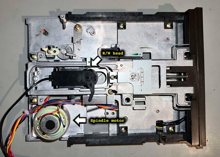
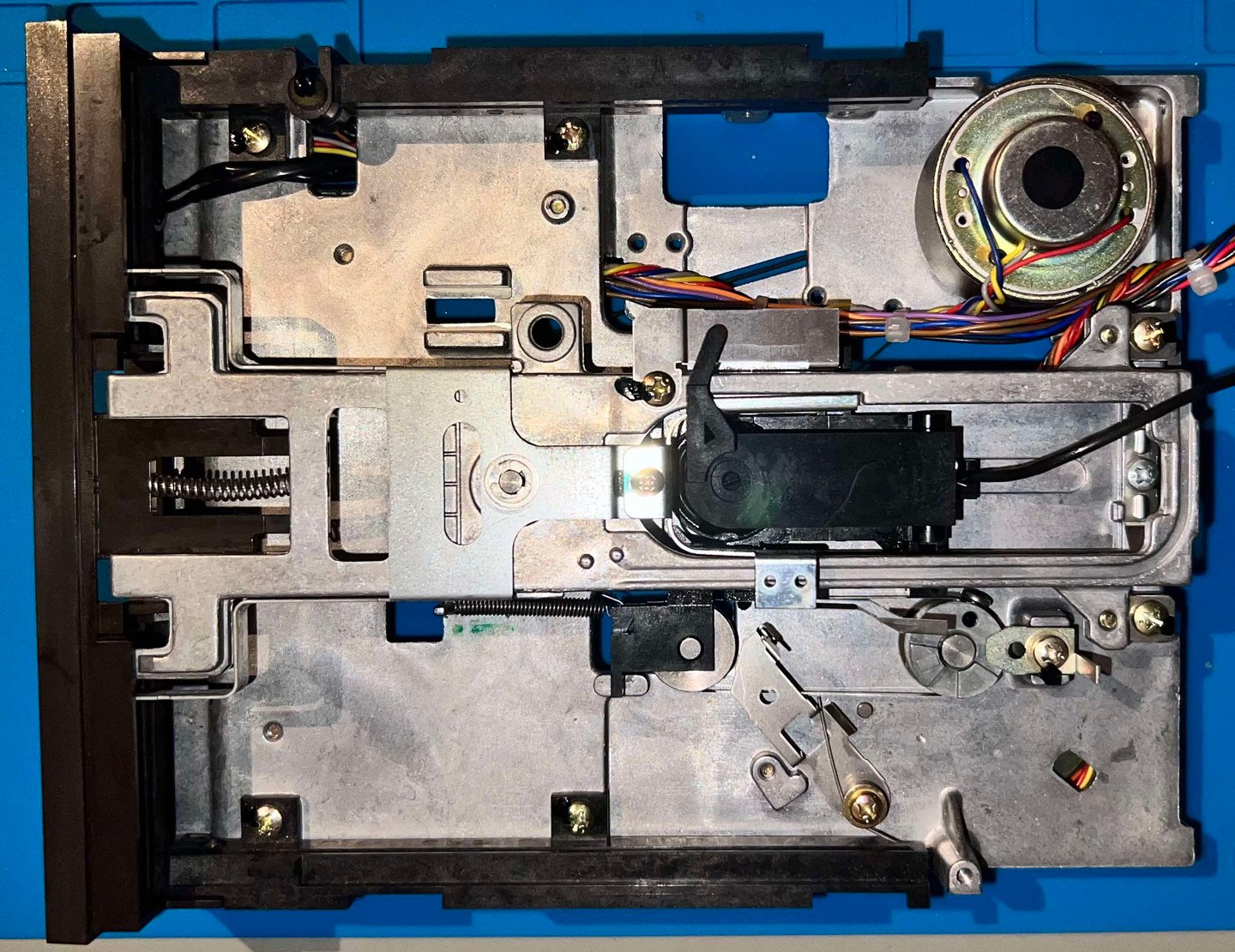
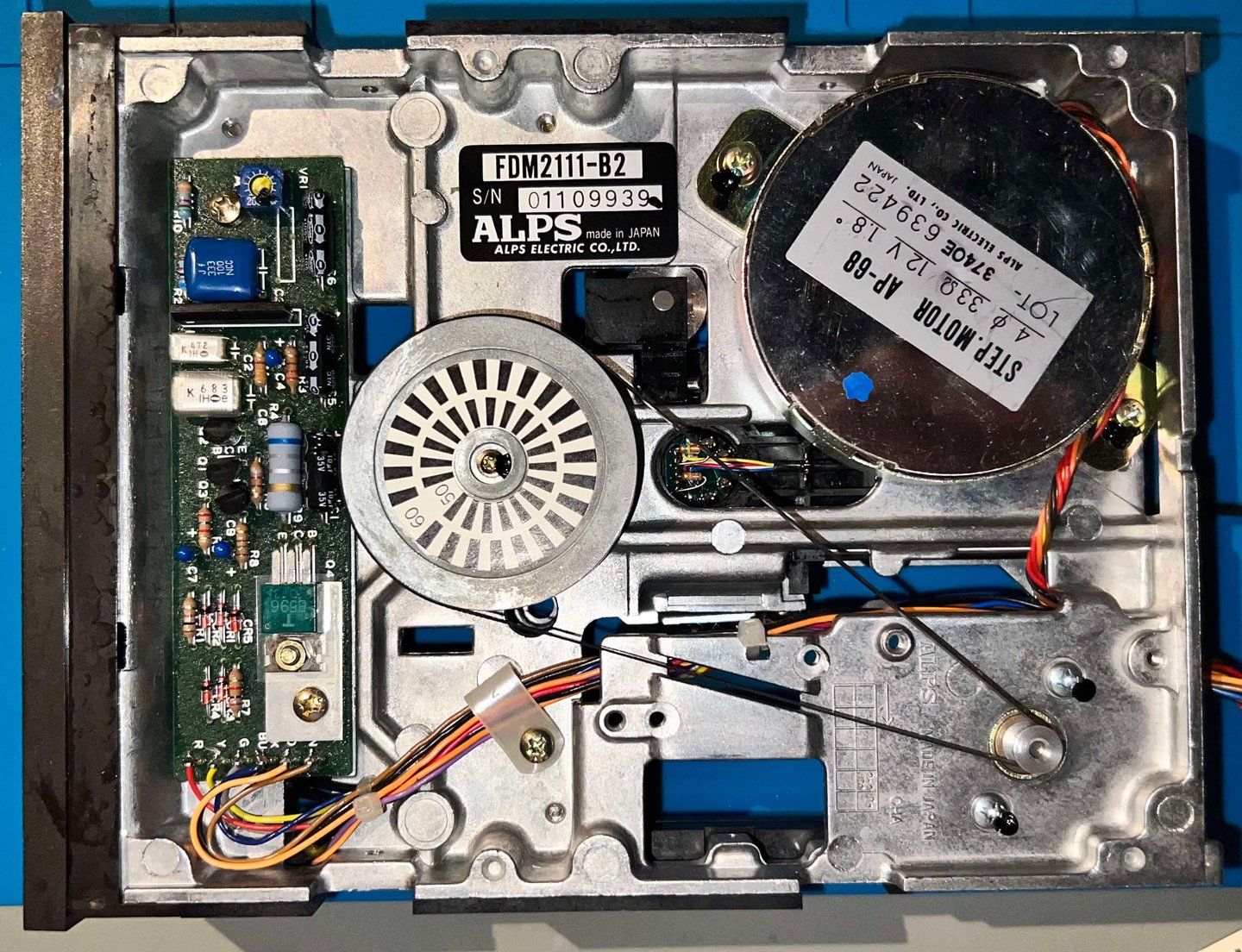
The drive mechanism looks to be in quite condition. Also, the drive belt seems to be just fine. There is the usual amount of dust and grease (and it is more dirty than it looks - pictures does not give it justice). The table below shows the version of this ALPS drive mechanism, step- and spindle motor.
Cleaning the R/W head
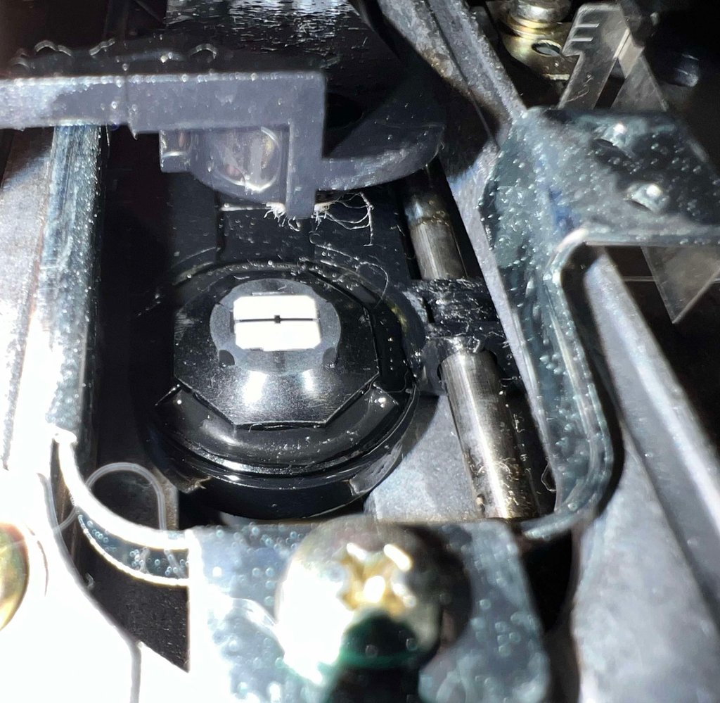
Having a clean R/W is crucial for the 1541 floppy drive to operate flawlessly. And after years of storage and use the R/W is very likely to be contaminated. Magnetic residue, and also mold (!), together with dirt and grease will be on the R/W head. Cleaning the R/W head is quite straightforward, but make sure not to lift the top of the mechanism (the one with the pressure pad) too high - to avoid that the spring loose its tension.
With some isopropanol and a Q-tip the R/W head is cleaned. Note that the residue can be quite tough so take your time cleaning. Below is a picture of R/W head after cleaning.



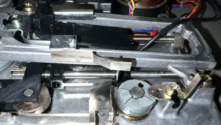
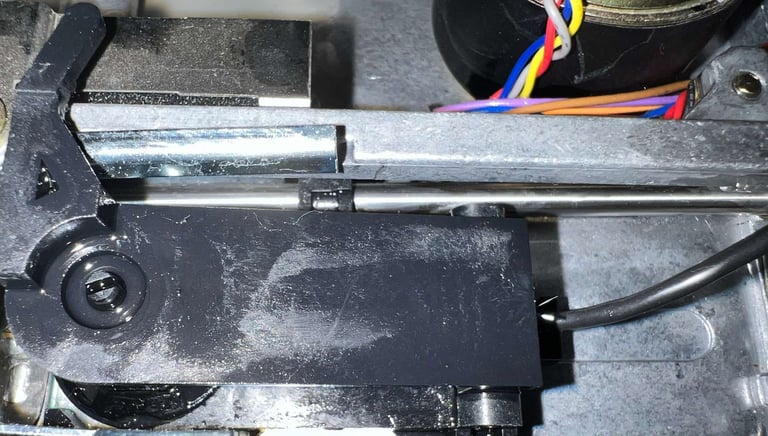
Cleaning and lubricating the R/W head rails
For the drive to operate as it should the R/W head must be able to travel all the way from track 1 to 35 (or even beyond). The stepper motor push / pull the R/W head while it is sliding along two metal rails. If these metal rails are not clean, and free from any corrosion, friction can cause the R/W head to fail in its attempt to position a track. So, as with the R/W heads, cleaning the metal rails is crucial for the floppy drive to operate properly.
There is a significant amount of grease on these rails. It might be that the R/W could travel up/down the rails, but I would assume that "hitting the track" all the time would be a challenge. With some isopropanol, a Q-tip and quite some time, the rails are cleaned. The pictures might not be too good, but the rails are now properly cleaned. Finally, a tiny drop of sewing machine oil on a Q-tip is applied to the rails.


Cleaning the spindle hub mechanism
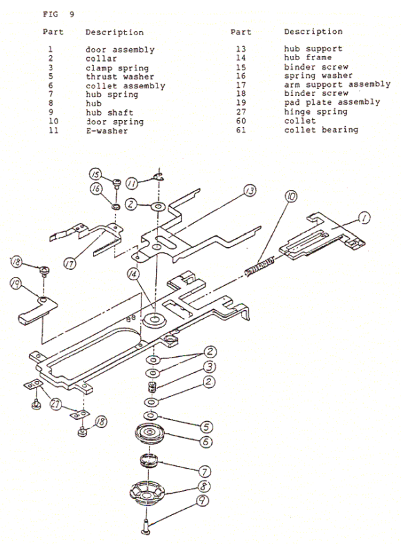
The rotating spindle hub can be quite "noisy" if it is not properly cleaned and lubricated. After almost 40 years this mechanism there are probably quite some dust particles and old grease stuck on this. But to clean this spindle hub the whole mechanism needs to be disassembled. Although not very difficult, it can be challenging to get all the small pieces back in the correct order. Below is an "exploded view" of the complete spindle hub mechanics used as reference.

Before the spindle mechanism can be accessed the front cover needs to be partly disassembled. There are two screws at each side of the front cover that needs to be removed. With the screws out of the way the front is tilted forward, and the door assembly is carefully pulled away from the front.

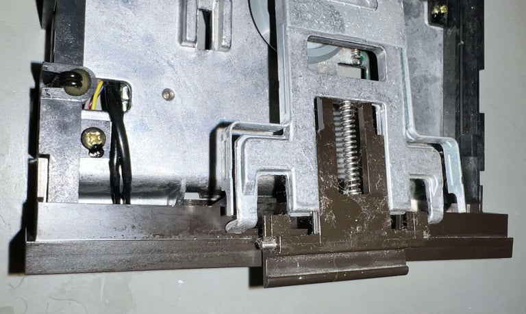

Disassembly is done through the following steps:
Remove the E-clip
Remove the fork and top spacer
Remove the the bottom spindle module
Below is a picture gallery from the disassembly process.
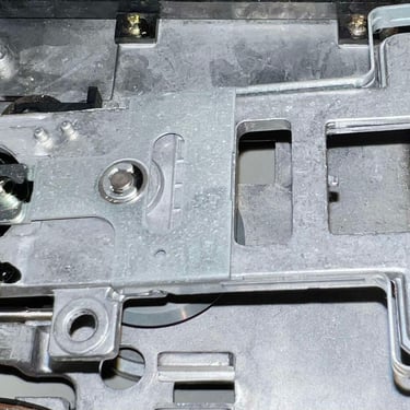
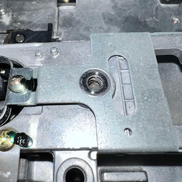
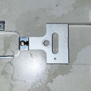
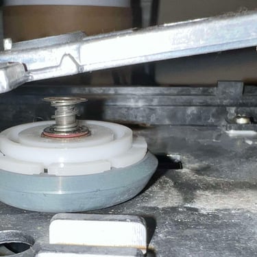
The individual parts which the spindle mechanism is composed off are cleaned with isopropanol. A tiny drop of sewing machine oil is applied to some of the moving metal parts.


All remaining areas are cleaned with isopropanol. Below are some pictures of the interior drive mechanism after cleaning and lubrication.


Initial testing
Before the next stage of refurbishing the disk drive is tested for basic operations. This is to check if the disk drive is in need of:
Repair
Alignment
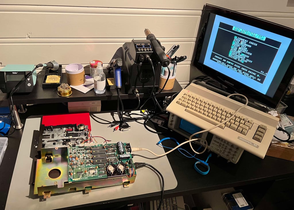
This initial testing is done with the floppy drive partially assembled. See picture below.
Resistances
There are three components in the 1541 which are made up of coils; the R/W head, the stepper motor and the spindle motor. A good indication to see if these work fine is to measure the resistance in the coils - see schematics below. The colors are found on the corresponding connector to the mainboard.
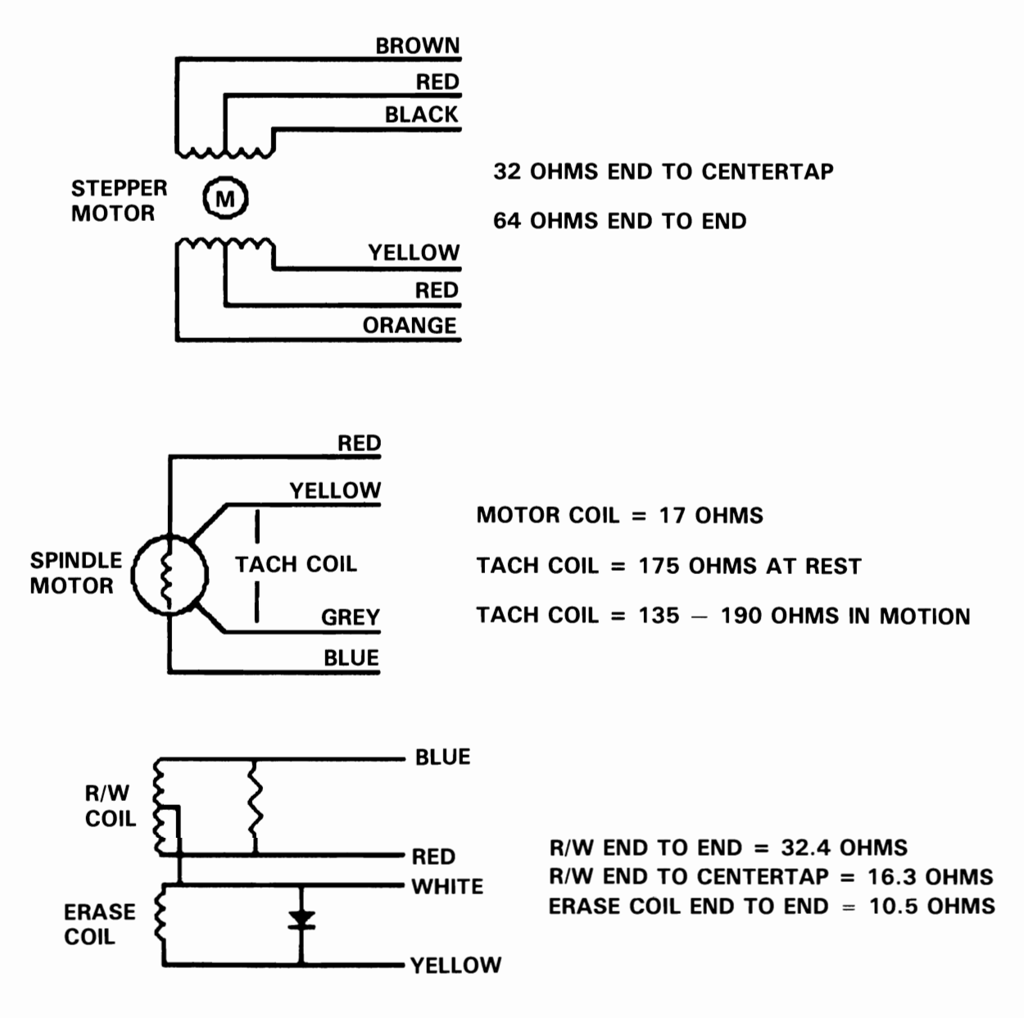

The results are listed in the table below. As can be seen from the table the spindle motor values are way higher than target (and not possible to measure the tach coil). I am not sure if this indicates any issue, or if this is just due to another type/manufacturer of the spindle motor. This will be checked during the basic testing. All other values looks to be within target tolerances.
Voltages
The 1541 disk drive is supplied by two voltages; 12 VDC and 5 VDC. These are transformed, rectified an regulated inside the drive. In the table below the measured voltages are listed.

Track 0, 1, 18 and 35 positions
The R/W head can read data between track 1 to 35, and in addition it can move all the way to track 0. The reason for the drive to move all the way to track 0 is that this is the absolute start of the drive position. By using the stepping motor the R/W head is moved - step by step - from track 1 to 35.
There are four positions which are checked:
Track 0 (absolute start of disk - no data read)
Track 1 (normal start of disk - first data track read)
Track 18 (initial position of disk on boot - BAM and directory)
Track 35 (normal end of disk - last data track read)
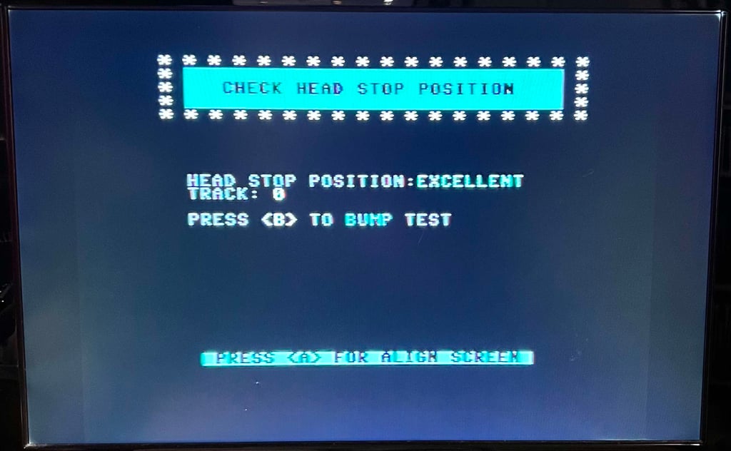
Track 0 is tested with the 1541/1571 drive alignment software. See picture below.

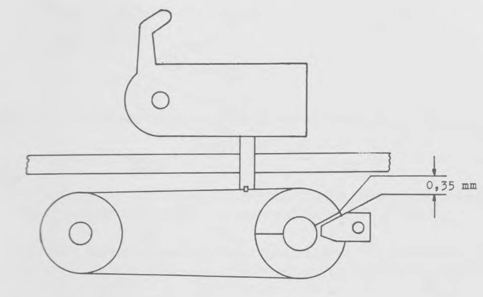
Track 1 is checked visually. As seen from the schematics below there should be about 0.35 mm between the stop ring and the stopper.

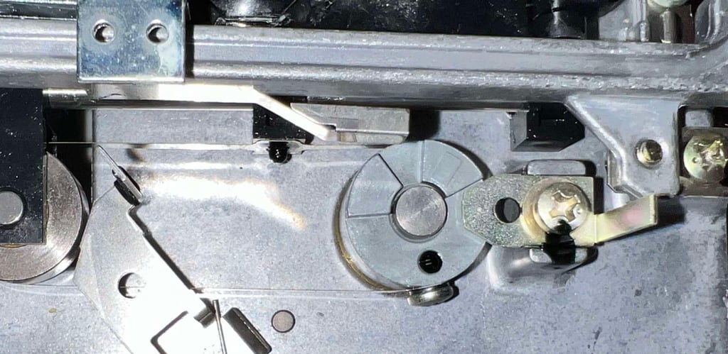
I don´t have proper tools for doing measurements this small. But it seems to be, from a visual perspective, to be about half a millimeter gap. See picture below.

Basic functionality
In the table below all the functionality tests are listed. Most of the test are done with the 1541 Test & Diagnostics cartridge (World of Jani) and 1541/1571 Drive alignment software from Free Spirit Software inc. This table will be used as a summary of the initial testing - detailed test results will follow after the table.
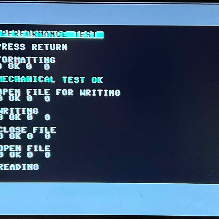
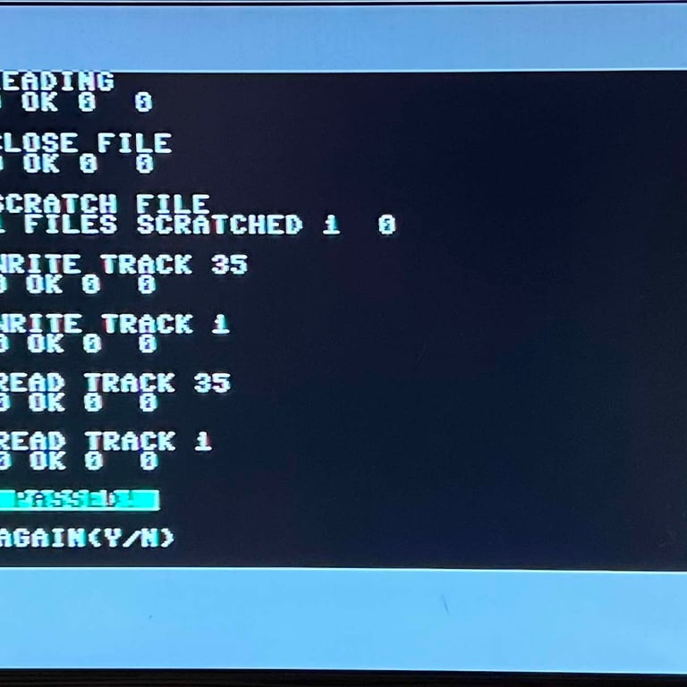
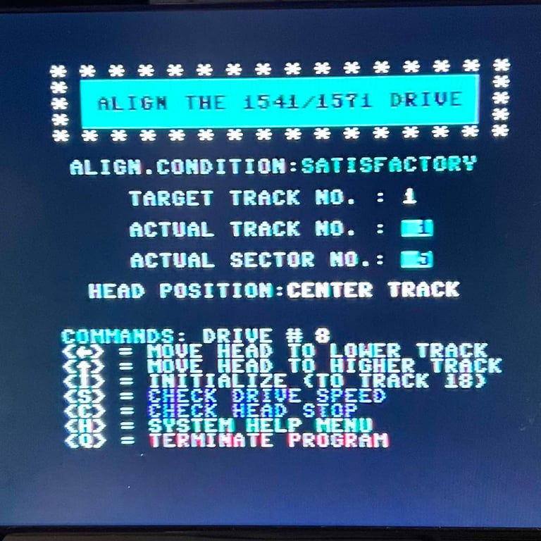
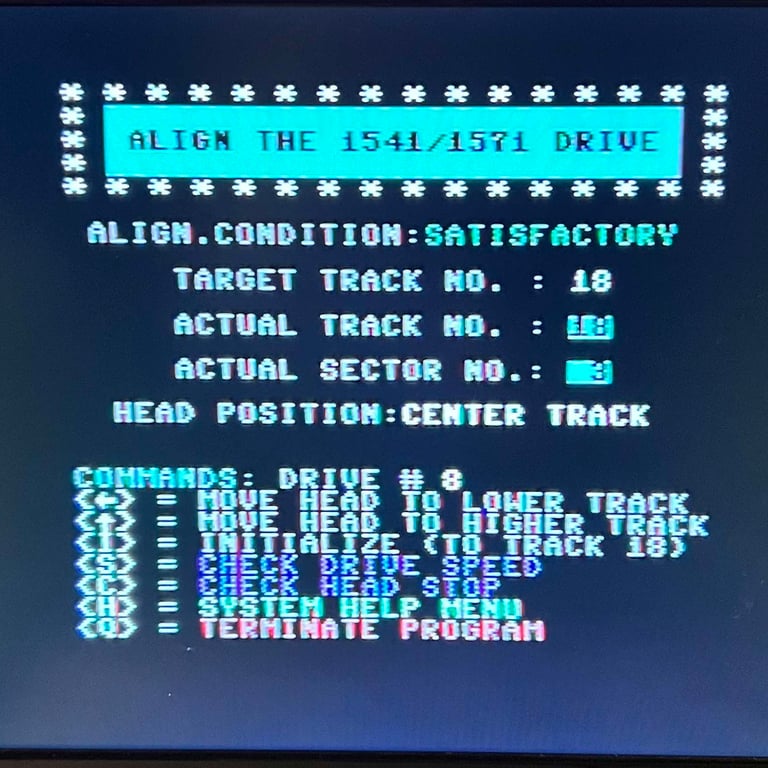
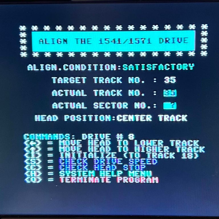
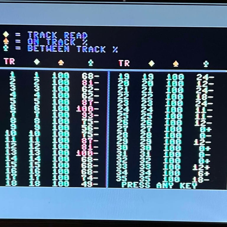
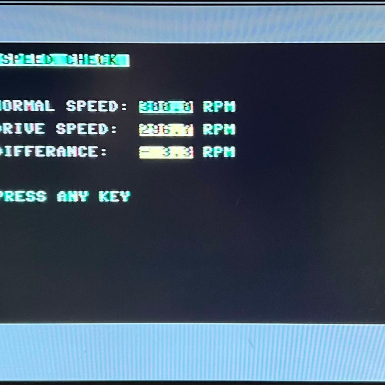
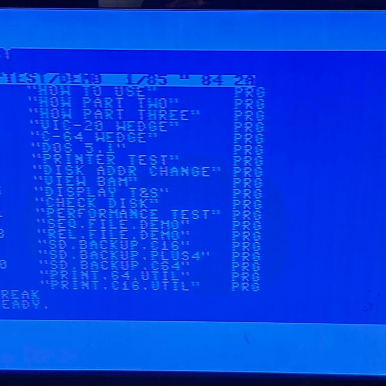
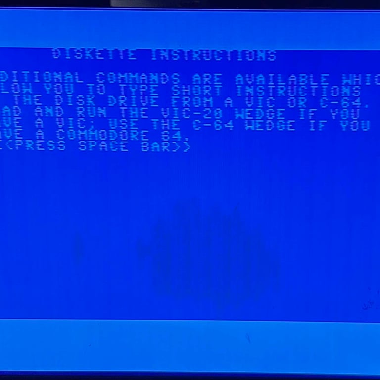
Conclusion stage #1
The initial testing is by no means an extensive testing. Note that the ROTATION SPEED is classified as "FAILED". This is not entirely true since the floppy drive can function fine with this RPM, but I will try to increase the speed slightly closer to 300 RPM. It looks to me that the drive´s basic functionality is in place so I will continue with stage 2 - replacing old parts.
STAGE #2:
Replacing old parts
Replacing the electrolytic capacitors - spindle motor control unit
There are three 10 uF [35V] axial electrolytic capacitors installed on the PY117 spindle motor control unit. All of these are replaced with new modern capacitors. No pads or traces were lifted during the process. Below is a picture of the spindle motor control unit with the new electrolytic capacitors installed.
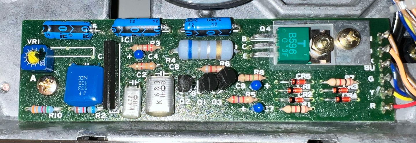

Replacing the electrolytic capacitors - mainboard
All of the electrolytic capacitors are replaced on the mainboard as well. The original capacitors were rated for 85 degrees Celcius, but the new ones are rated at 105 degrees. Its not that the temperature in the 1541 floppy drive will ever reach such temperatures, but my hypothesis is that with a higher temperature rating the capacitors are likely to survive more hours in a hot environment. Note that on the spindle motor control unit the original 85 degrees capacitors are used as this board is at the bottom and never gets hot.
Below is a picture of the mainboard with the new capacitors installed. No trace or pad were lifted during the process.
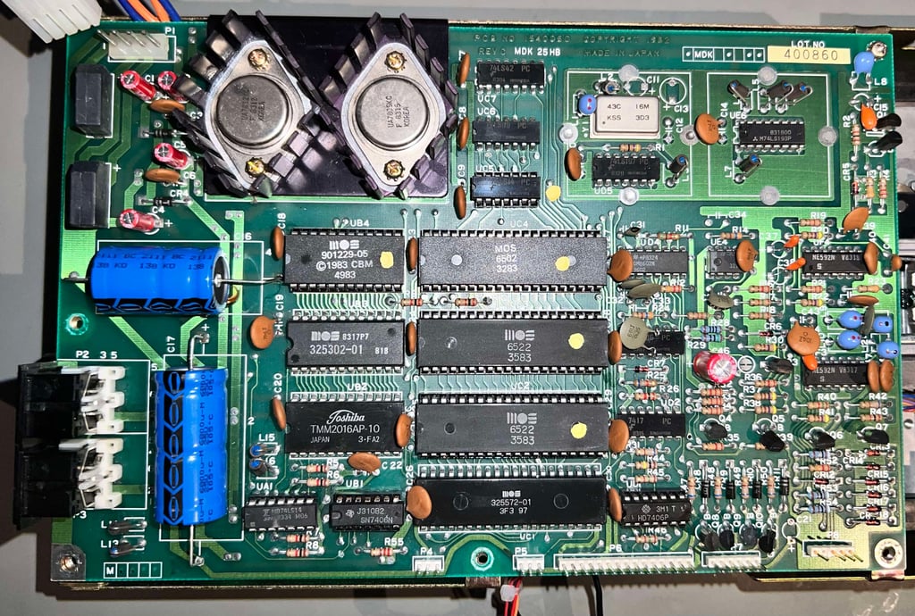

The larger capacitors, C16 and C17, were originally glued to the PCB to make sure that they don´t move while the drive is vibrating. The new capacitors are way lighter, and would not suffer from a large momentum due to vibrations, but the capacitors are glued to the PCB nevertheless.
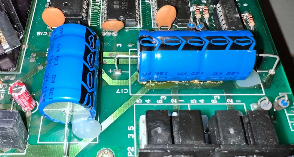

Adjusting the rotational speed
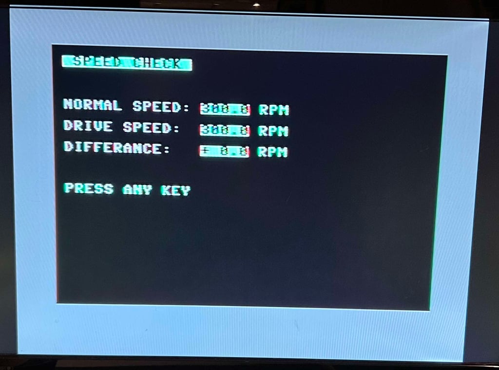
For the 1541 floppy drive to operate flawlessly the rotational speed of the spindle motor must be approximately 300 RPM. During initial testing this was measured to be about 296 RPM. It is still within tolerance, but I would like it to be a bit closer to 300 RPM.
To adjust the rotational speed the small potentiometer at the bottom of the drive is turned. And with the 1541 Test & Diagnostics cartridge from World of Jani installed the rotational speed can be measured.
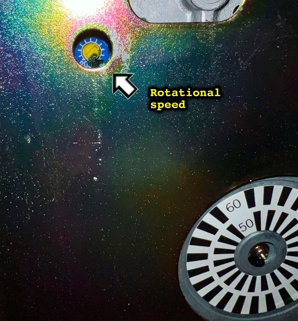

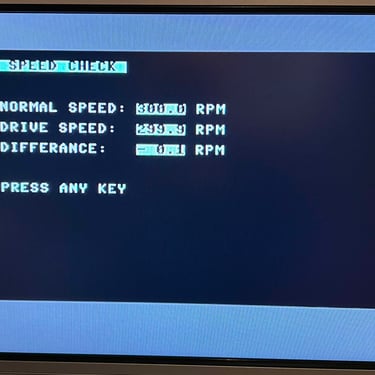
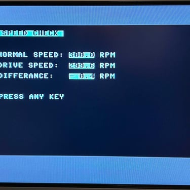
The drive is adjusted so that it reads 300 RPM. Note that the drive speed will vary slightly during reading; in the area of 299.6 - 300.0.

STAGE #3:
Testing and verification
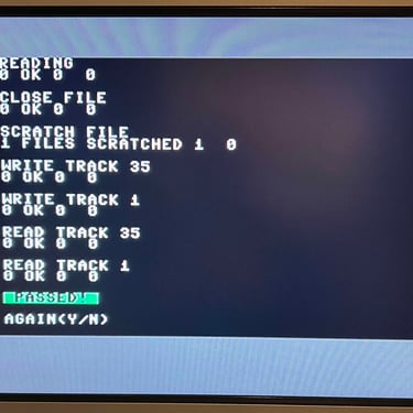
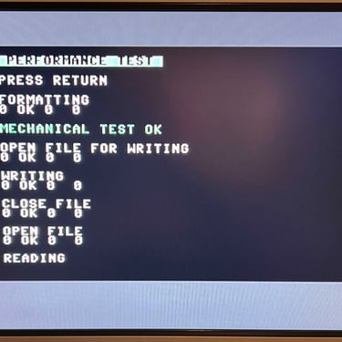
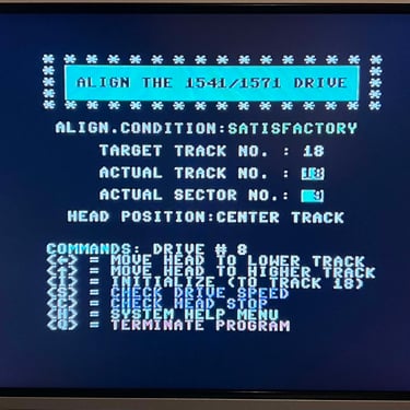
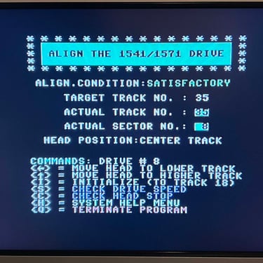
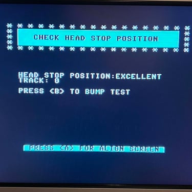
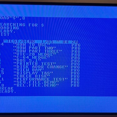
The purpose of this stage is to test, and verify, that the 1541 floppy disk drive works as it should. Basic functionality were tested in stage #1 and now everything is re-tested and verified. A combination of software tools are used in this process - please see description of tools.
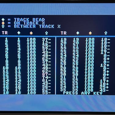
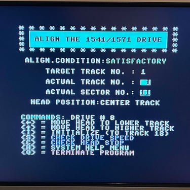
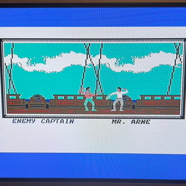
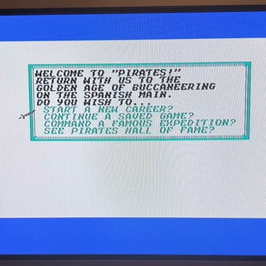
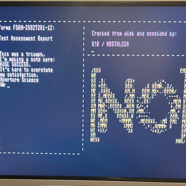
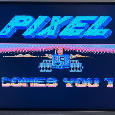
In the table below are the results and at the bottom some images from the testing are shown.

Final result
"A picture worth a thousand words"
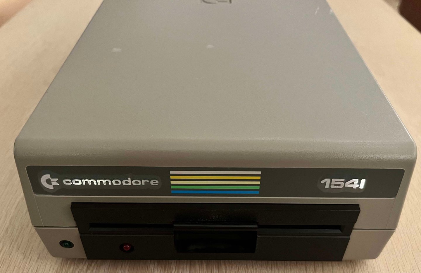
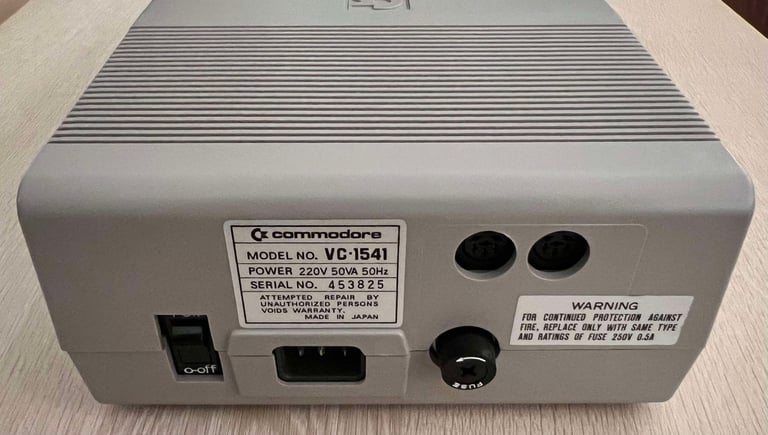
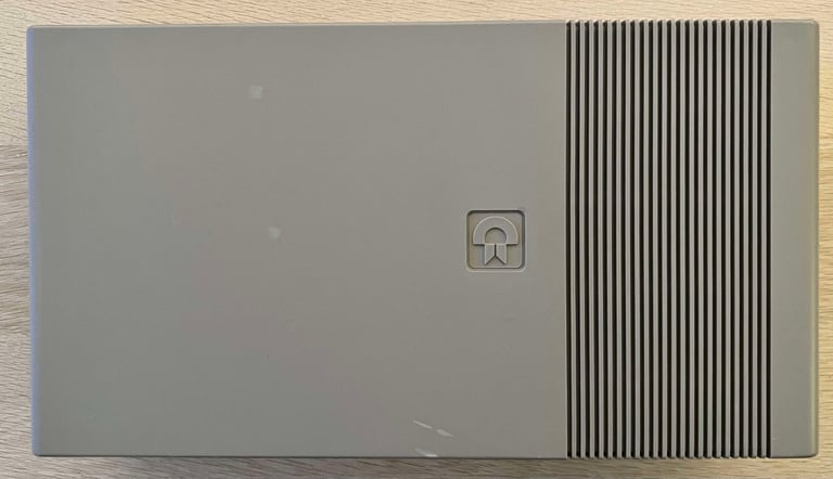
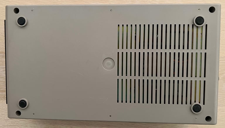
Below is a collection of the final result from the refurbishment of this 1541 floppy drive. Hope you like it! Click to enlarge!





"Are you keeping up with the Commodore? 'Cause the Commodore is keepin up with you!"
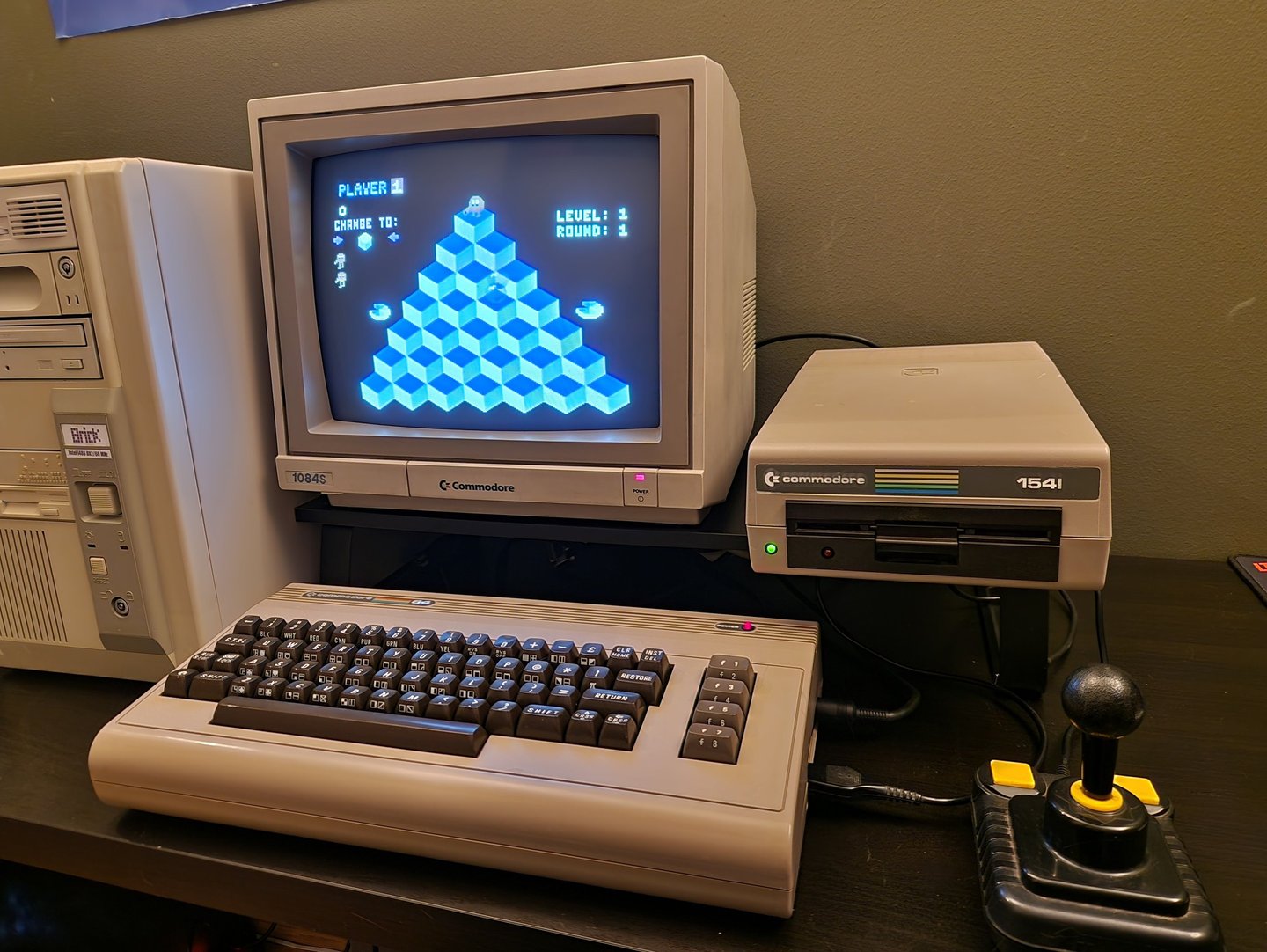
Below are some pictures of the 1541 floppy drive back at the customer´s home!

Banner picture credits: Medvedev
