

Amiga 500 Internal Drive
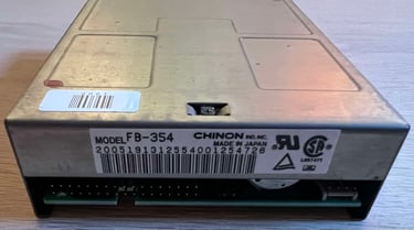
Ser. No. 2005...1254726
Model FB-354
Chinon
Starting point
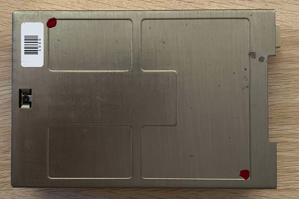
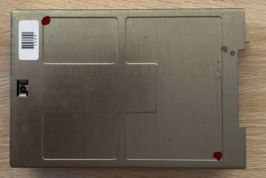
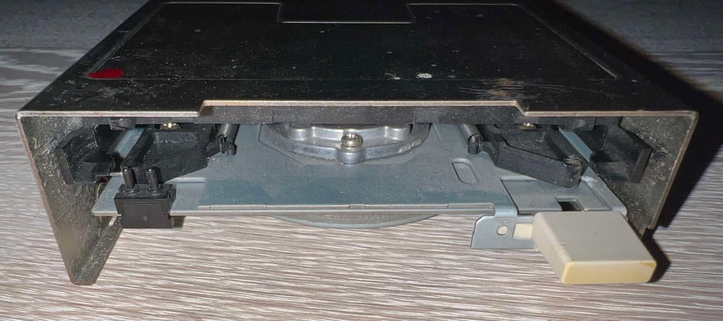
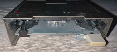
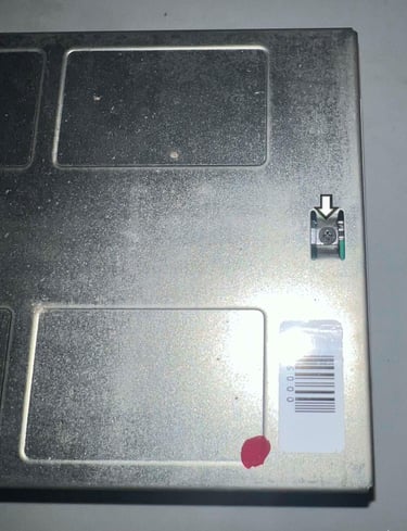
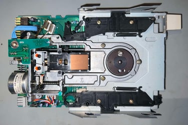
From the outside this internal Amiga disk drive looks to be in very good condition. Unfortunately, it is known to be not working (or only partially working). There is some dirt and grease visible inside the drive, but it is not exhaustive. The eject button is slightly yellowed, but it appears to be in good condition otherwise. I can not see any obviously faults with this drive that should cause the drive from malfunctioning.
This is a Chinon FB-354 disk drive probably used in an Amiga 500. Also, it has the longest serial number I have seen: 2005191312554001254726.
Refurbishing a not-working (or partially working) internal disk drive is not always a success. Due to mechanical tear and wear some of the metal and/or plastic parts may be too worn for proper functioning. But, it can also be the case that with some proper cleaning, and replacements of old electrolytic capacitors, that the drive can become working again. Let´s hope for the best!
Below are some pictures of the internal disk drive before refurbishment.


Refurbishment plan
To refurbish this internal disk drive the plan is to do this trough the following actions (some of them in parallell and different order):
- Clean the interior
- Clean special parts such as R/W head and stepper motor shaft
- Replace electrolytic capacitors
- Verify operation by testing
Initial test
Before the disk drive is disassembled a quick initial test is done. The drive is installed in a stock Amiga 500. To do the initial test the Amiga Test Disk is used.
Below is a table showing the results from the initial testing.
As can be seen from the table above the disk drive is partially working. There are two tests which points in the same direction:
The read test is struggling with tracks in the range from 25-50. Its not so that all of these tracks fails - the disk drive first detect a read error, but it will immediate retry a few times until it succeed.
The head calibration test shows that R/W head is struggling (the results varies) with cylinder 40.
In short: when the R/W head is about half way reading the disk it is struggling to read steadily.
Disassembly
To remove the top cover three screws needs to be removed; one on each side and one on the top. Notice that these screws are quite small so keep them in a safe place for later.

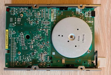
The lid is carefully slid off to the side - this reveals the interior. There is quite some dust and grease inside, but looks to be in good condition otherwise at first glance.

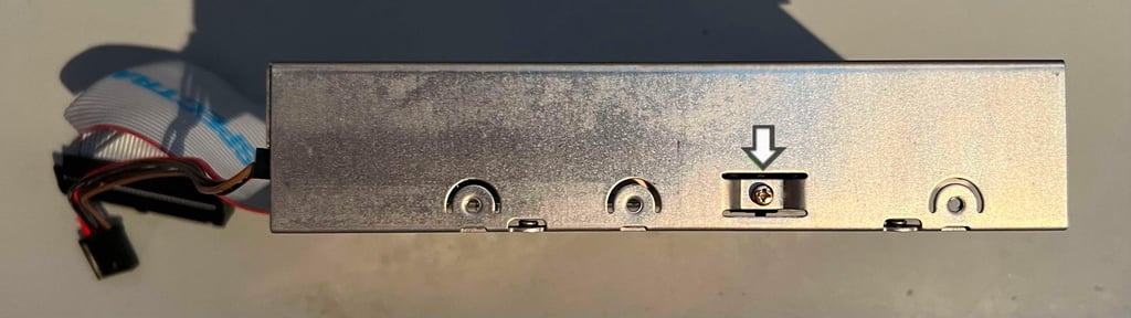
Next action is to remove the special screw holding the carriage in place in the chassis. Note the word "special". This screw is hard to replace if you loose it...

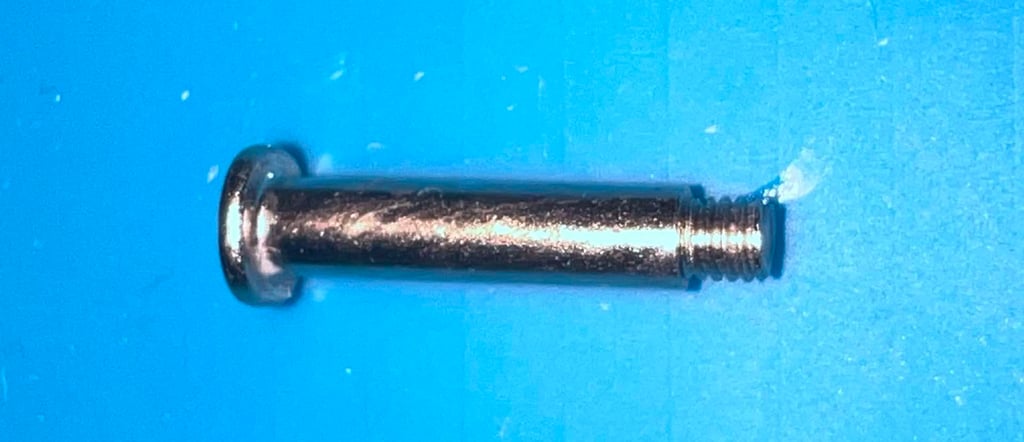

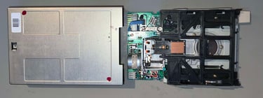
With the screw out of the way the floppy carriage can be removed by gently pulling it to the side. But make sure to keep the read/write head clear from any obstacles! You do not want to damage the R/W head when removing the carriage! I use a small spudger tool to hold the R/W head out of the way when dragging the floppy carriage out of the way. Also, make sure that when you remove the spudger that the R/W head as carefully been closed again (so that the up- and down R/W head slam together).
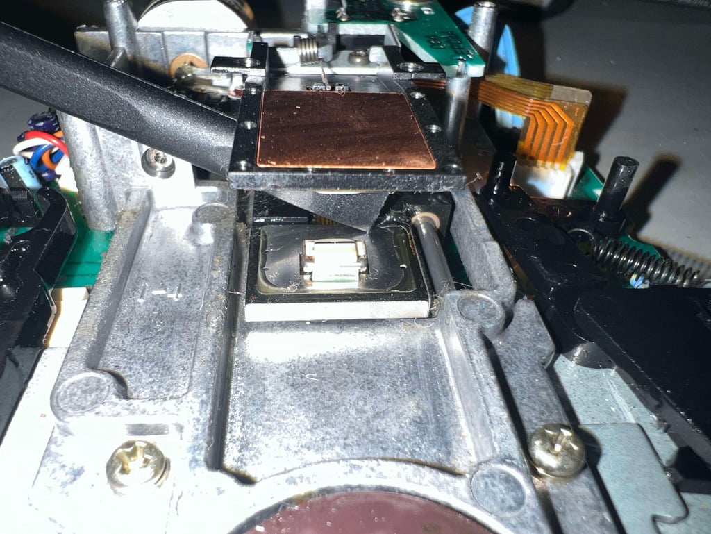
When the floppy carriage is removed the complete floppy area is revealed. It looks to be in fine condition, but quite dirty (the picture does not do it justice - it is worse than it looks...).
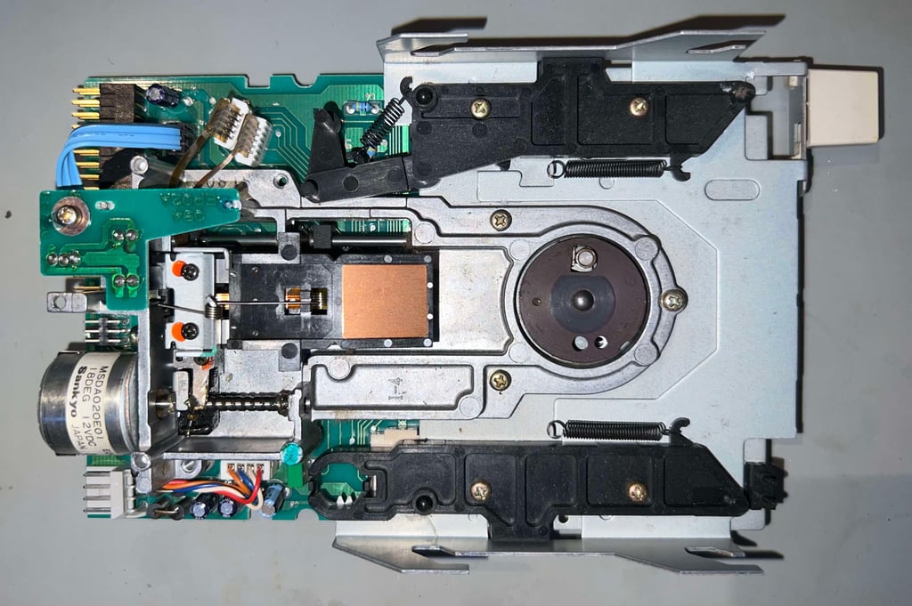
At this point the disassembly stops. Further disassembly will risk misalignment of the R/W head and the track zero sensor. If it turns out that these are already misaligned further disassembly might be required.
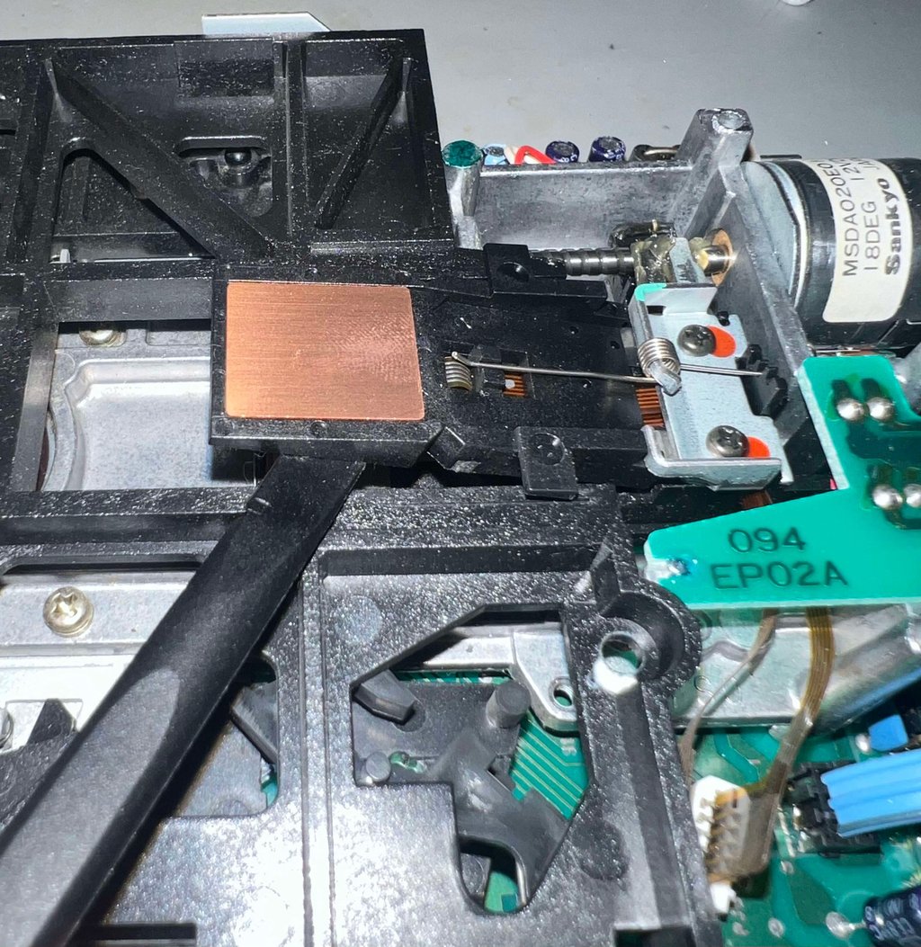
Interior electronics and mechanics
Cleaning and lubricating
The whole interior is cleaned properly with isopropanol and brushed with an antistatic brush. This removes most of the dust and grease. In addition the read/write heads are cleaned using isopropanol and a Q-tip. NOTE: the Amiga disk drive consists of two R/W heads. One at the bottom and one at the top. The R/W head mounted on top of the bracket is way more fragile so be very careful when cleaning this.
Another area which is cleaned with uttermost care is the stepper motor shaft/spindle. This is full of old hard grease (which could prevent the R/W heads from moving up/down the rails). After cleaning the shaft is lubricated with some new multi purpose grease.
See pictures below from the cleaning and lubrication of the R/W heads and the stepper motor shaft.


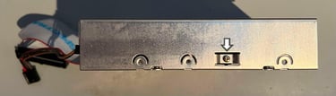
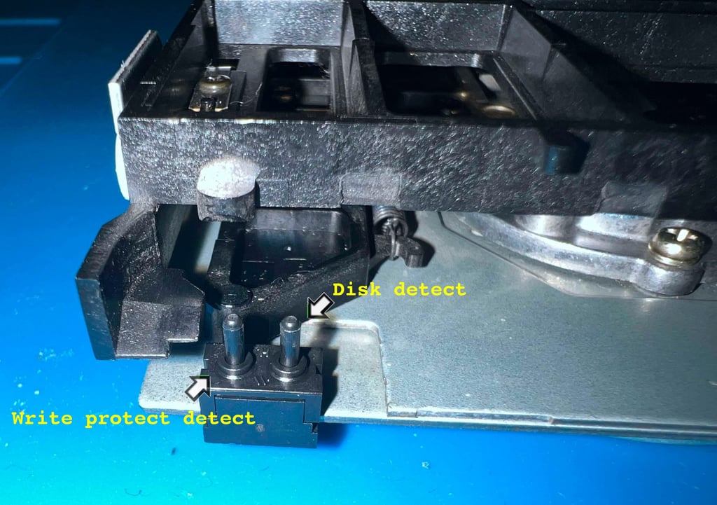
Another are which requires special attention is the two detectors to register:
When a floppy is inserted
If the floppy is write protected
A small double-switch is used for this purpose. It is not uncommon that this switch can be quite oxidized preventing the drive from detecting if a floppy is inserted (and write protected). To fix this some contact cleaning spray can be applied to the switch. NOTE: these switches are quite fragile! So when applying the contact cleaner let it soak a while before applying pressure to the switch. This is to prevent that the liquid is pressed too hard - too fast - and damaging the interior of the switch.

To make sure that the new grease is properly smeared over the stepper motor shaft, and also providing a small test of the drive, is to connect the drive to an Amiga 500 and run the Amiga Test Disk Kit (ATK). And with this software make the R/W heads move up/down along the shaft. This will make sure that all the grease is properly smeared. See short video below.

Replacing the electrolytic capacitors
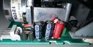
As can be seen from the capacitor list the Chinon FB-354 consist of four electrolytic capacitors; 1 x 50 uF [50V] and 3 x 22 uF [16V]. New capacitors (the 22 uF have a higher voltage rating which is fine) are installed. See pictures below.

Testing
FAST FORWARD:
After quite some extensive testing a fault is getting more and more prominent - until it is permanent (?). It appear that what causes the floppy drive to fail from time to time (and after quite some testing fails all the time) the "Track Zero Detector" is not working.
In the disk drive there is a small photodetector which senses when the R/W head is in "Track Zero" position. But it turns out that this detection is not done! It just continues all the way "banging the head" in the wall.
But I wonder? Did the refurbish provoke this fault to be permanent? I think so. In the beginning I had problems getting floppies to boot, but after a few attempts it did work. But after cleaning, recapping and extensive testing the fault appear to be permanent. Argh...
This drive is probably possible to repair by changing the Track Zero detector, but the cost is higher than getting a new one unfortunately... so this drive will be used as spared.
In the video below you can see when the R/W moves all the way to the left. If you compare this to the other video (above) you can see where it should stop.

THE LONGER STORY
This is still a drive which will be used for spares, but in an attempt to repair (or get a better understanding of the fault) the following is done:
The original 22 uF [16 V] capacitor is put back replacing the new 22 uF [63 V] capacitor. This does seem to help a little. The drive is still struggling to find track zero, but I think that it is a little better (ok, I know this is subjective, but this is really hard to measure).
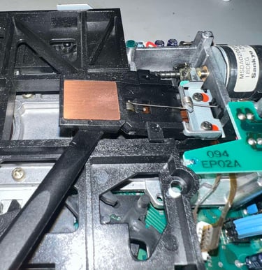
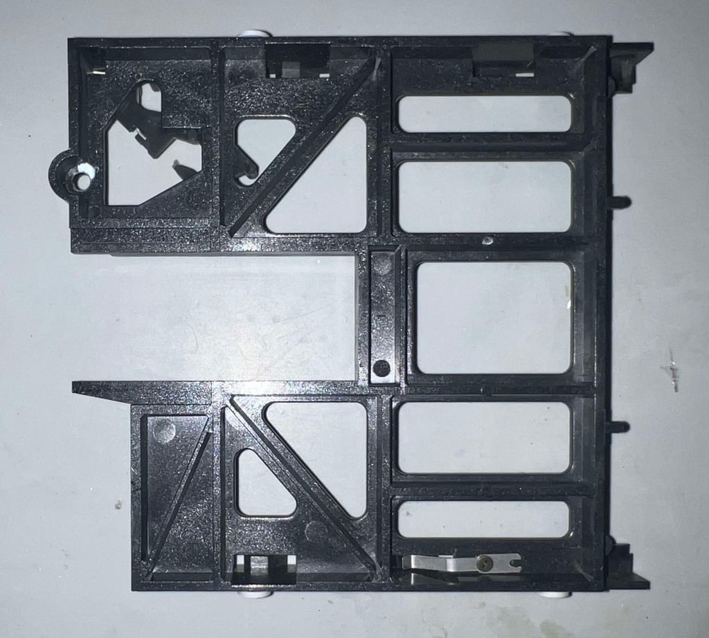
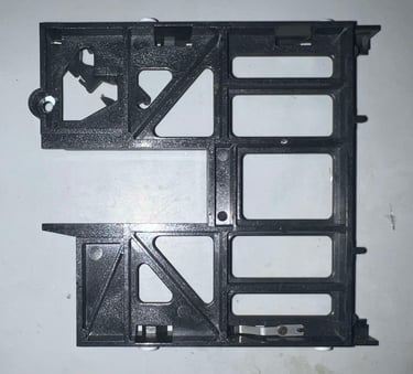
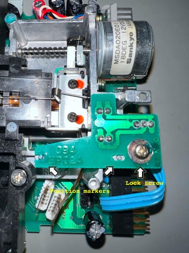
The track zero detector is unscrewed from the chassis. This WILL mess up the alignment of the drive, but since this drive is already in a poor condition this still makes sense. I can not see any visual damage (or dirt) which should cause the sensor to malfunction, but it is cleaned with some isopropanol nevertheless.
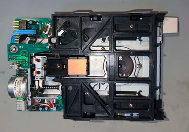
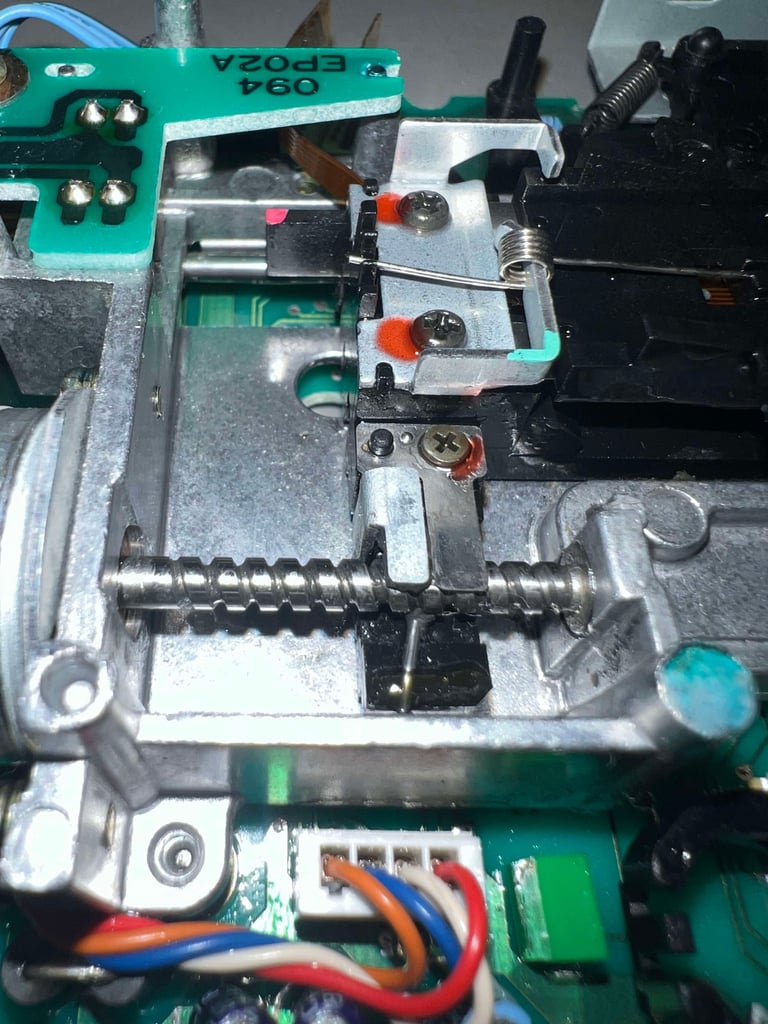
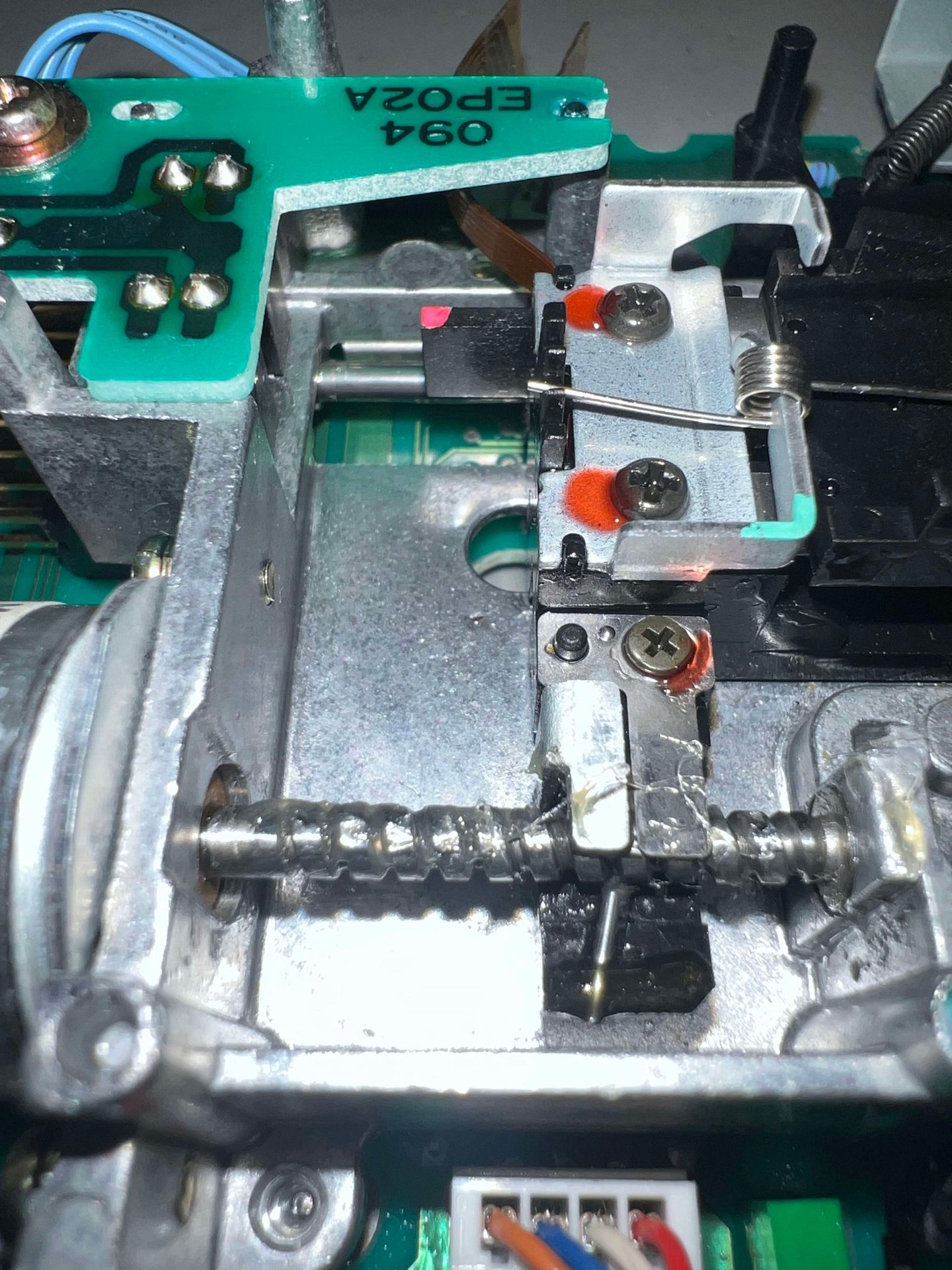
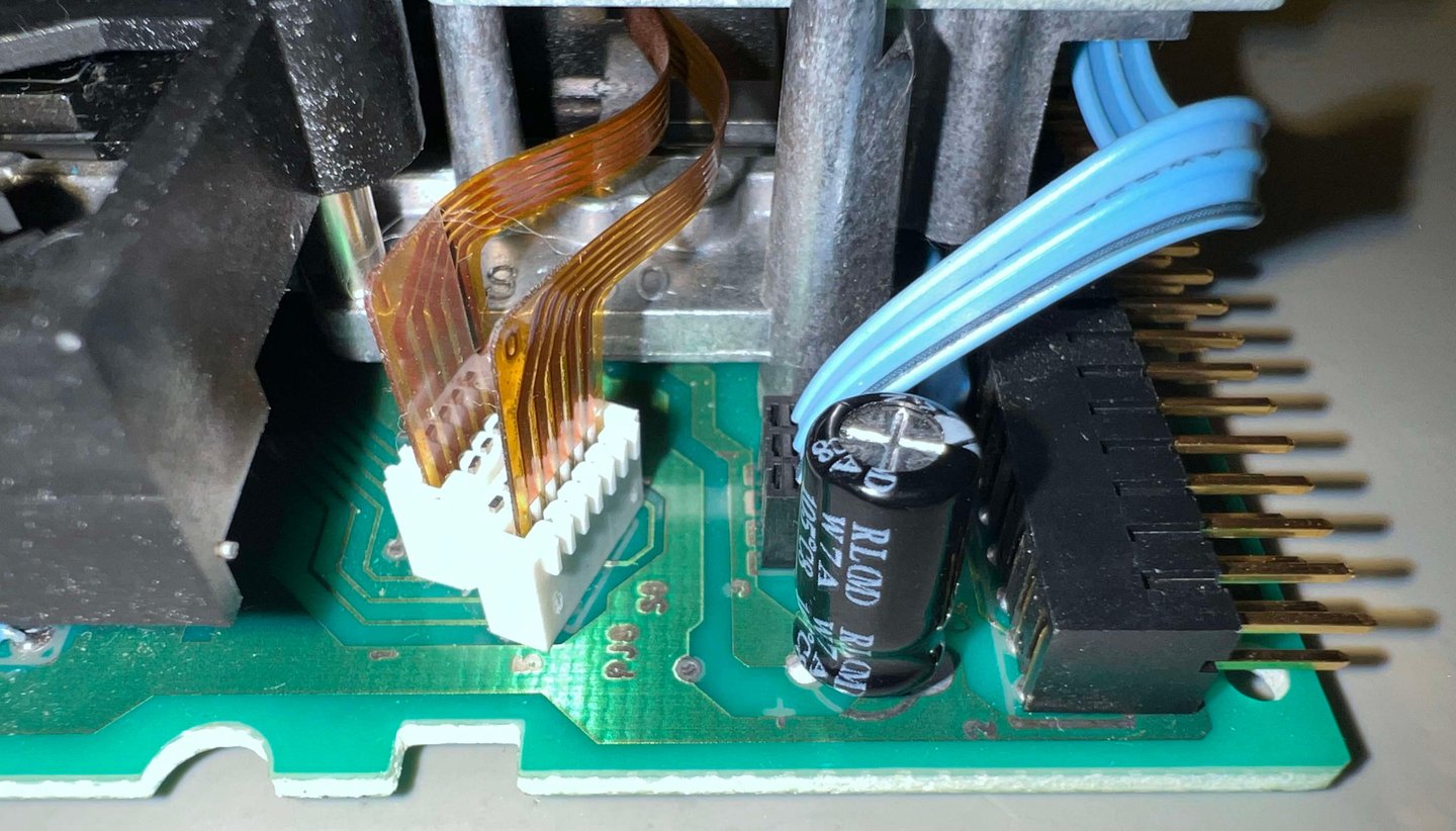
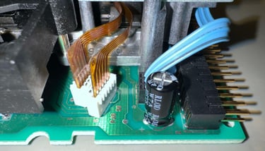
Below is a picture of the track zero PCB before disassembly. Note that this PCB needs to be aligned 100 % for the drive to work (alignment is done at production time). Getting the track zero back in position afterwards is very hard.

As a matter of fact the performance do improve quite a lot after disassembly and reassembly. The problem with the stop position for track zero not detected is still present, but it is not too frequent. I still think the problem is related to the photo detector and/or the circuitry related to registrering the position.
In an attempt to describe the status of this defect drive (which will be used for spare - unless a miracle occurs):
When the track zero detection fails no disks are able to boot. The disk drive is clicking fine, but the R/W head keeps banging in the walls until it gives up.
When the track zero detection works the results are in the table below
CONCLUSION
As mentioned a few times this internal disk drive will be used for spares unfortunately. Is it possible to repair it? Yes, I think it is possible, but I think that the cost for replacing parts (such as the track zero detector) - and the time used for 100 % alignment - is not worth it. Also, there is a significant risk that there is also the problem can also be related to worn mechanical parts.
Banner picture credits: Medvedev