

Amiga 500 Internal Drive
Ser. No. 229253
Model JU-253-033P
Panasonic
Starting point
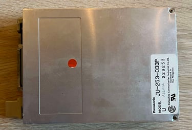
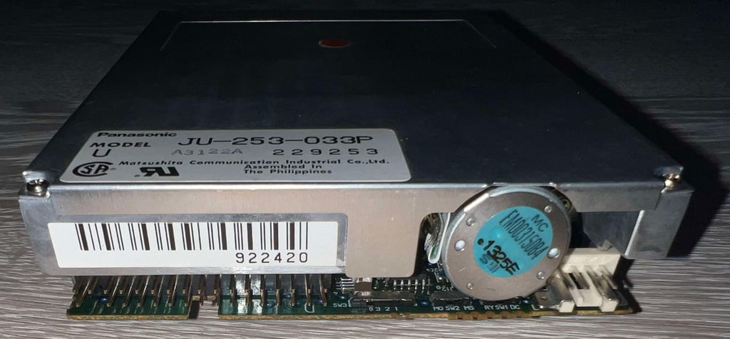
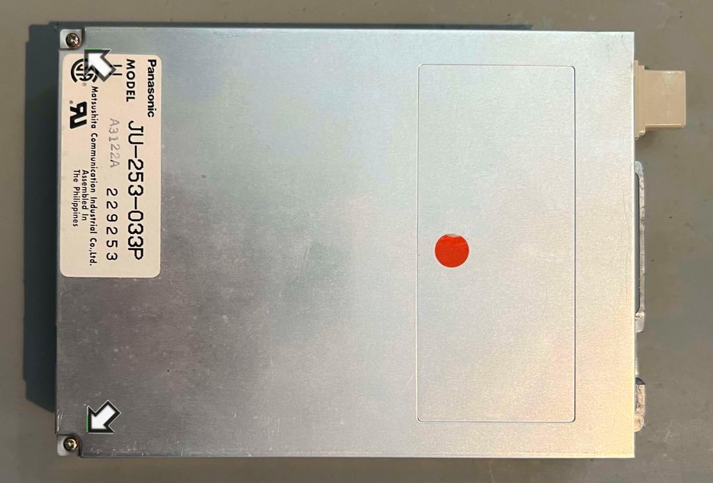
Another internal Amiga disk drive - known to be "not working". This is a Panasonic (aka Matsushita) JU-253-033P which is a quite common disk drive used for the Amiga 500 back in the days.
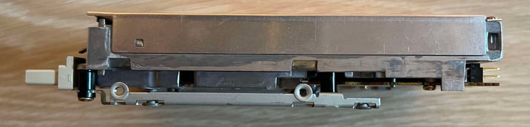
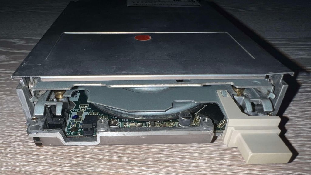
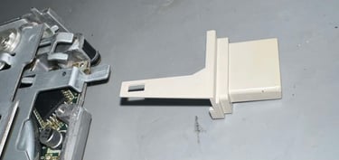
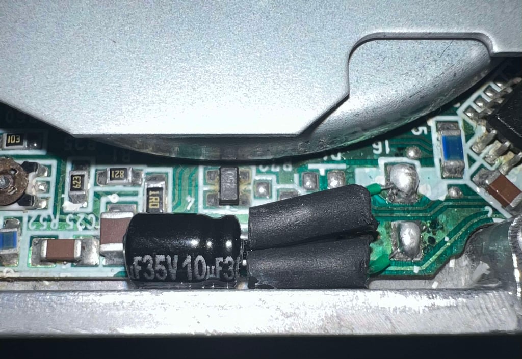
From the outside it seems to be in quite good condition. Some dust and grease, but I can not see any immediate signs of damage. The eject button is only slightly yellowed and undamaged. But I do notice that there is a SMD electrolytic capacitor looming in the front of the drive... I wonder...
Repairing these disk drives can be a real challenge, and it is not always possible to fix them (at lease to me). If the mechanical parts are too worn out the R/W head will easily be challenged to "hit the right spot" on the disk. But quite often these drives are simply just full of old stuck grease preventing the R/W head from moving up/down the shaft - and the old electrolytic capacitors can be leaking. I´ll give it a 50/50 chance for success.
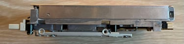
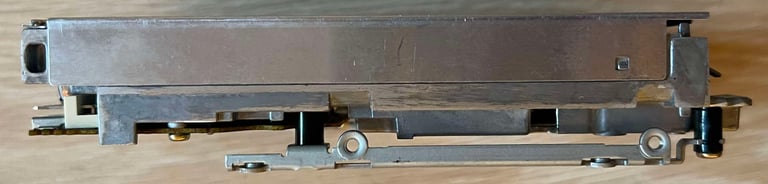
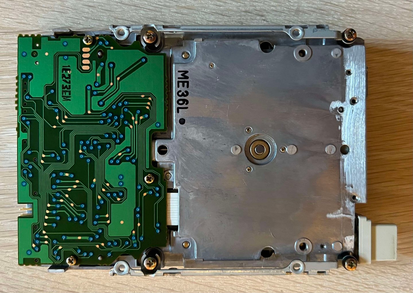
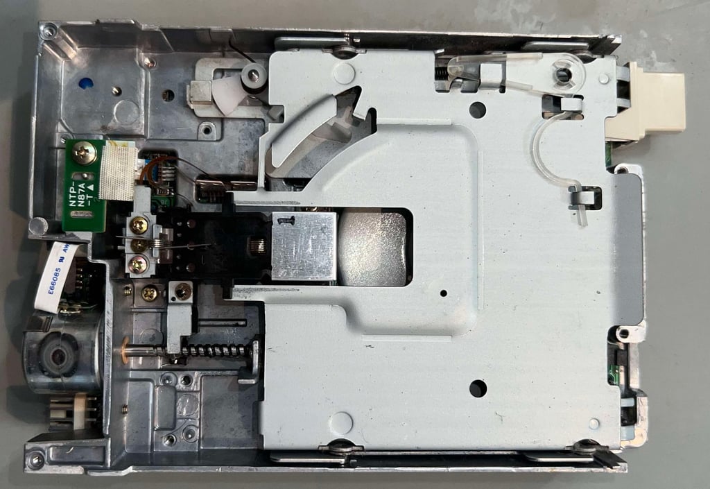
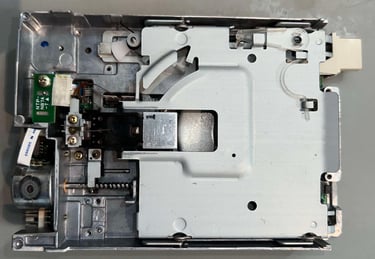
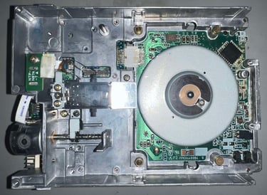
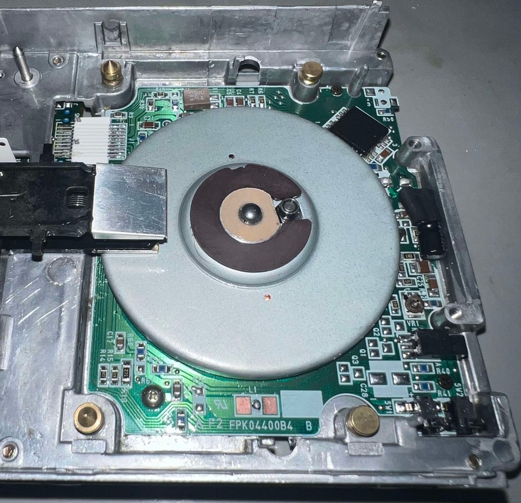
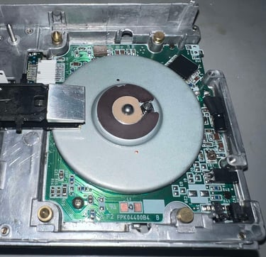
Below are some pictures of the internal disk drive before refurbishment.


Refurbishment plan
To refurbish this internal disk drive the plan is to do this trough the following actions (some of them in parallell and different order):
- Clean the interior
- Clean special parts such as R/W head and stepper motor shaft
- Replace electrolytic capacitors
- Verify operation by testing
Inital test
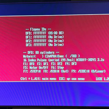
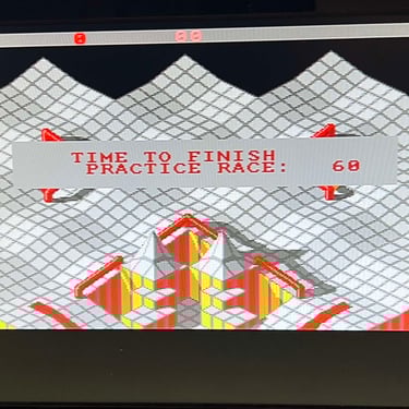
Before the disk drive is disassembled a quick initial test is done. The drive is installed in a stock Amiga 500. To do the initial test the Amiga Test Disk is used.
Below is a table showing the results from the initial testing.
As can be seen from the table above this internal Amiga disk drive has serious issues. The drives does power on and makes the nice "ticking" sound, but for all floppies I try to boot it fails. The boot-screen goes away for a few seconds and returns - nothing else happens.
Disassembly
Disassembling an internal disk drive is not difficult - if you know what do disassemble and know where to stop. If you disassemble too much you risk that parts such as the stepper motor and/or the track 0 detector gets misaligned. And even if its possible to align a misaligned drive this is something that is quite challenging and should be avoided if possible.
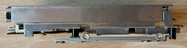
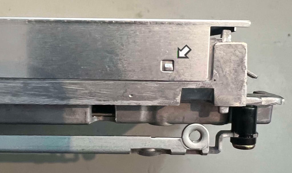
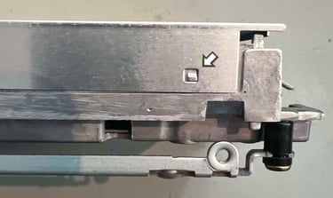
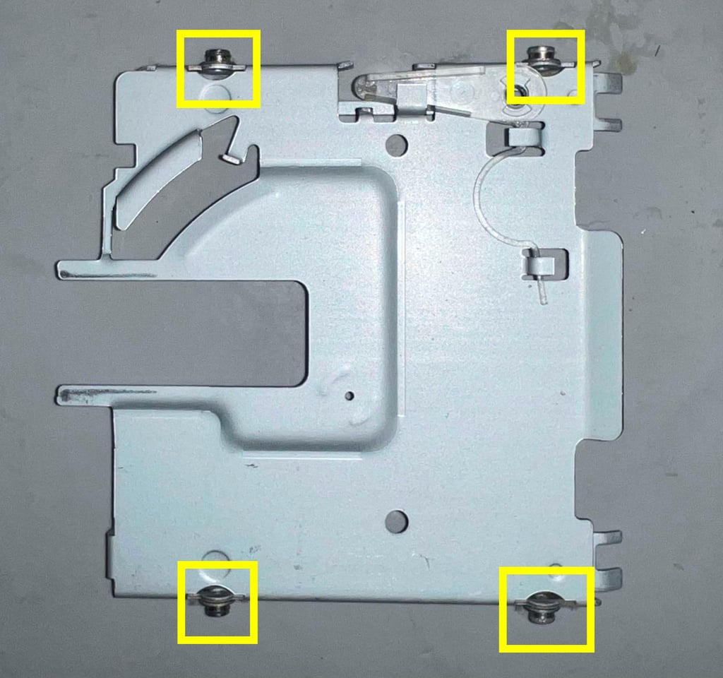
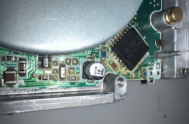
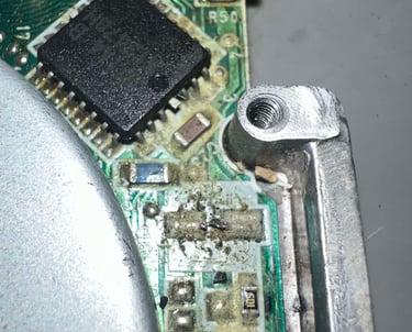
First step of disassembly is to remove two small on the far end of the top cover. See picture below.
With the screws out of the way the top cover is ready to be lifted away. But before that can be done the lid needs to be freed from the small tabs on each side of the drive. By applying a thin small flat screwdriver the cover is pried open.
The interior is now revealed. I can see immediate that there is quite some cleaning required, but otherwise it doesn´t look bad at all.
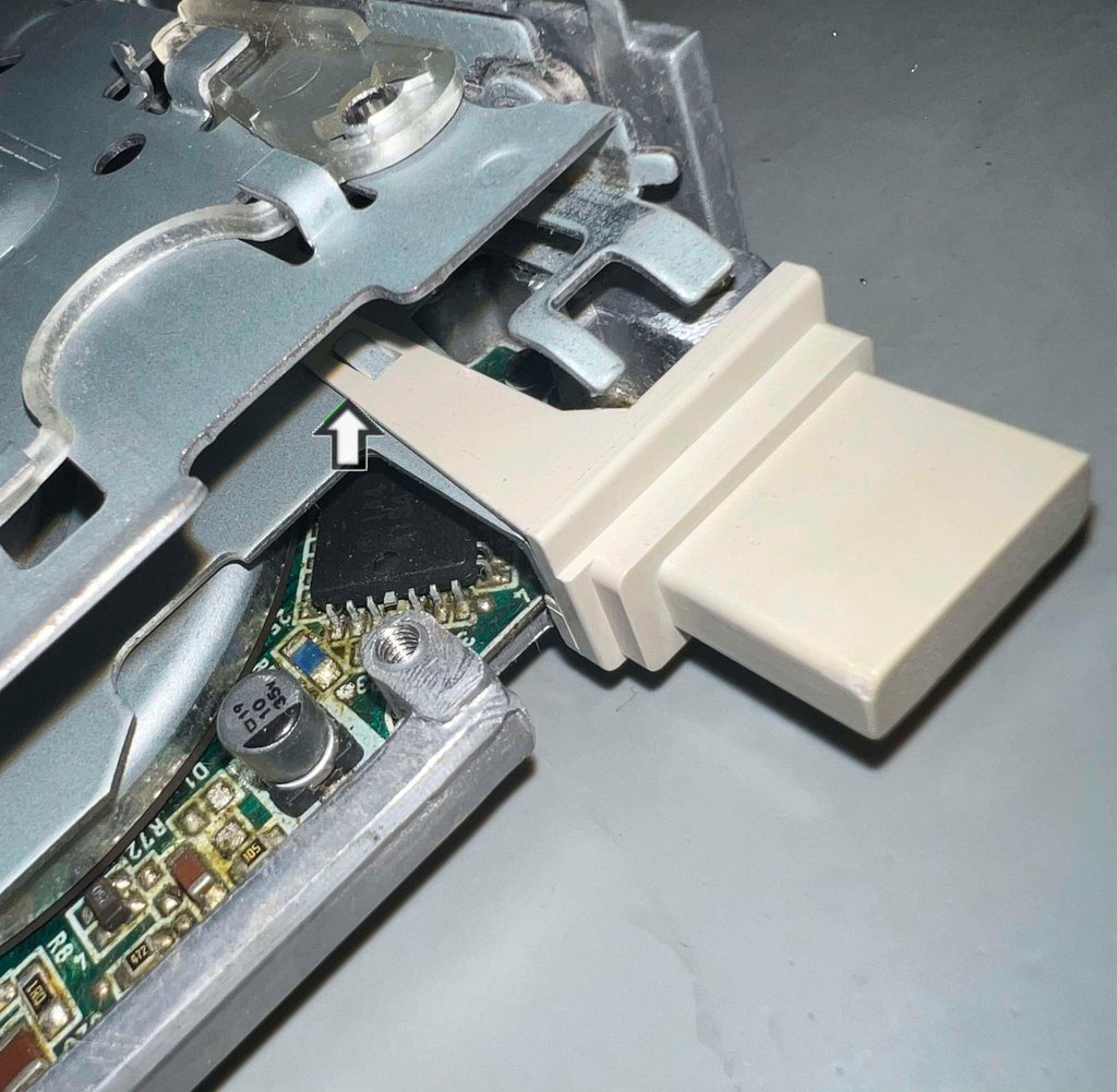
Next action is to remove the eject button. It might sound counterintuitive, but it is essential that this button is removed since this button will prevent further disassembly. To remove the eject button it is carefully lifted away from the metal tab using a flat thin screwdriver. I stress the word carefully - this plastic is old and brittle and can easily break.


Removing the top of the floppy carriage is not difficult - if you know the "trick". Also, keep in mind that the floppy top carriage part contains four very small metal wheels which are VERY easy to loose if you don´t pay attention! And trying to find these later can be quite a challenge... so keeping the carriage in a small plastic bag can be a nice idea!
To remove the top of the carriage the following steps are taken:
The eject button (without the button) is pushed all the way in
The two metal wheels are now freed from the carriage and can be lifted upwards
The two remaining wheels are carefully pulled towards the front and the carriage is free
WARNING: When performing the third step make sure that the read/write head does NOT slam together risking to break this! With a small tool, such as a pair of tweezers, keep the R/W head lifted when the carriage is removed.
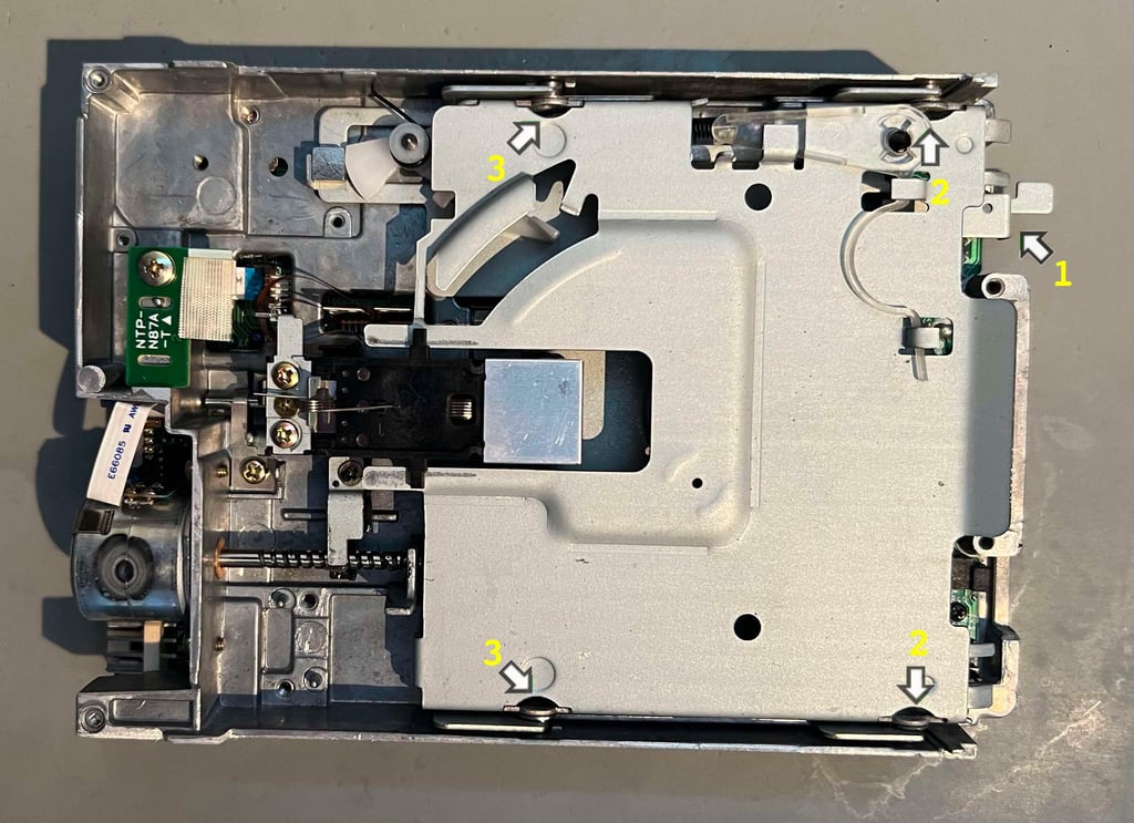
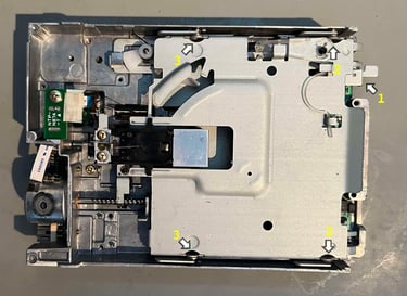
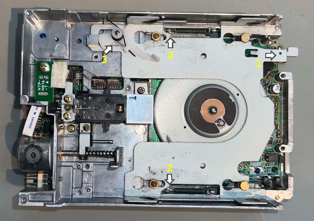
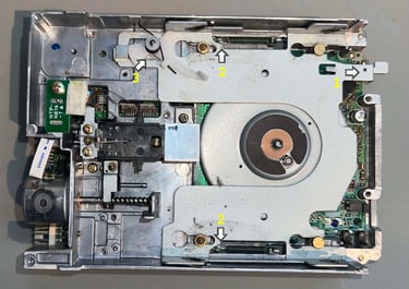
See pictures below of the position for steps #1-3 and how the carriage looks when step #2 is performed.

Below is a picture of the top part of the carriage. Notice the position of the four metal wheels (you do NOT want to loose these...).

Now we are ready to disassemble the bottom part of the carriage. This is a bit more "tricky" operation, but not complicated if you do it in the right order:
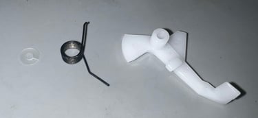
Push the bottom carriage as far right as possible. This will reduce the stress on the springs (2) to a minimum
With a pair of tweezers the two springs are carefully removed
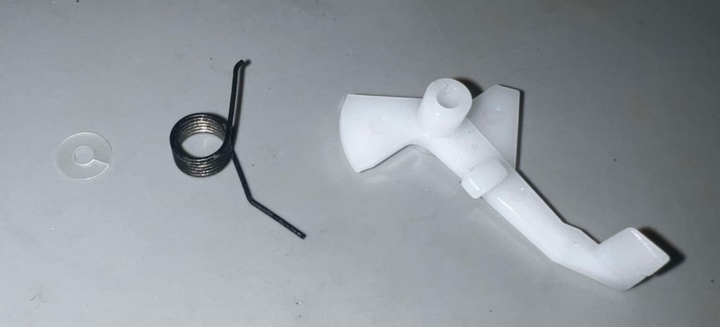
The plastic stop mechanism is disassembled and removed in the following order: first the plastic clip, then the spring and finally the plastic piece.
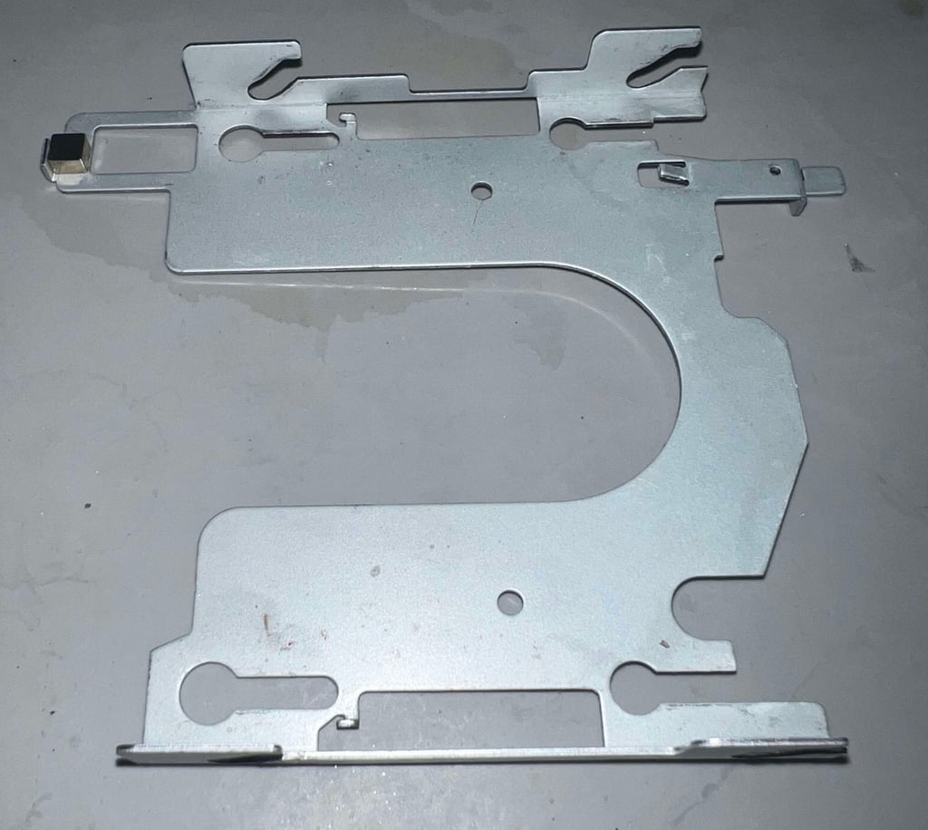
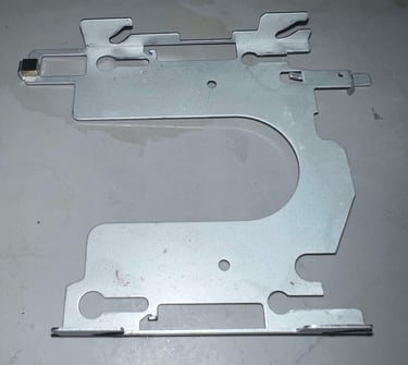
The disassembly is now complete (hopefully). This is the place to stop disassembling without risking that the alignment of the stopper motor and stop sensor are disturbed. Below is a picture of the disk drive disassembled.
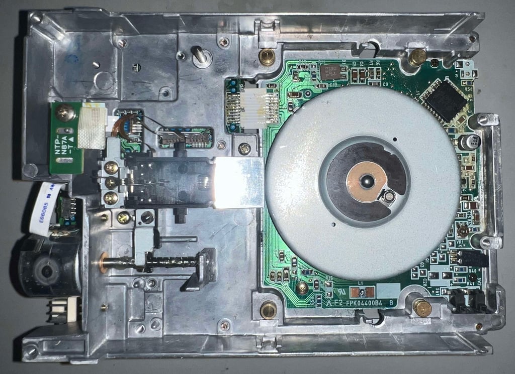
Interior electronics and mechanics
The interior shows a significant issue: an electrolytic capacitor which has leaked. As can be seen from the picture below, this 10 uF [35 V] capacitor has spilt its dielectric all over the PCB...

Since the leakage is so severe the electrolytic capacitor is cut out using a pair of quality diagonal cutters. And as can be seen from the picture below the pads are completely covered with the leaked dielectric goo.

The pads, and the area surround these, are cleaned and a new electrolytic capacitor is soldered in. Note that this is not a SMD capacitor, but that is fine. The new capacitor is laid alongside the PCB and glued to the board.

There is a lot of leakage on the PCB. So the PCB is cleaned properly with plenty of isopropanol and an antistatic brush. This is a quite tedious operation, but the end result is quite good. See picture below.
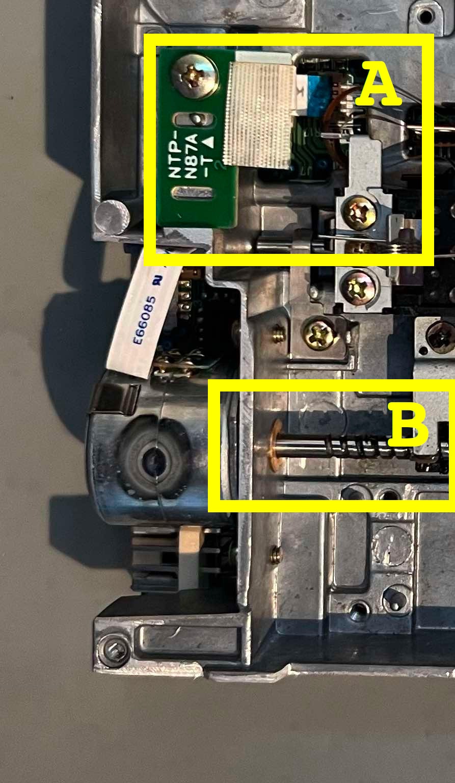
Finally the track zero sensor (see "A" in picture below) and stepper motor shaft (see "B" in picture below) are properly cleaned with isopropanol. Also, the stepper motor shaft is lubricated with some multi purpose grease.

Testing
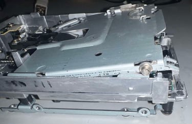
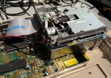
To test the internal drive an Amiga 500 is used - setting the refurbished drive on top of the original disk drive.

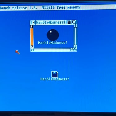
So, does it work? The short answer is yes! It works really well! It "eats" all the floppies that I can throw at it. But how did that came about? Read the full story below.
The first test was a failure. No change. Not able to boot anything. Then the disk drive was disassembled and cleaned again. Next test is way better! Now it starts to read some of the floppies (for example it can read the Amiga Test Kit once). Another complete disassembly and cleaning. This times it works even better than before - more and more floppies can be heard. But I notice that from time to time comes a high pitch noise and/or some "grinding" sound. The drive is disassembled a last time - cleaned and lubricated - and then... just as the floppy "awakes". It works just 100% - flawless! Wow!
So what happened? I am not really sure if there was some residual leakage from the capacitor or if the drive was so dirty that it had to be cleaned and lubricated several times. Also, the new capacitor also did help on the situation.
NOTE: This drives works really well now. But I do think that in order to stay this way it needs to be used. "Use it or loose it". If not, grease will probably start to accumulate and could prevent the drive from proper operation.
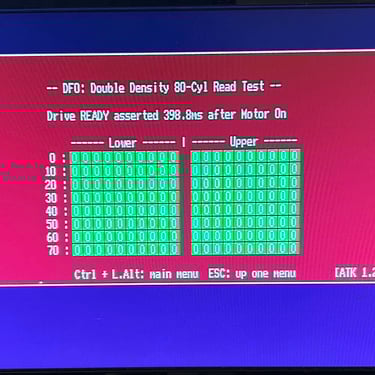
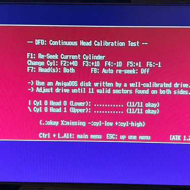
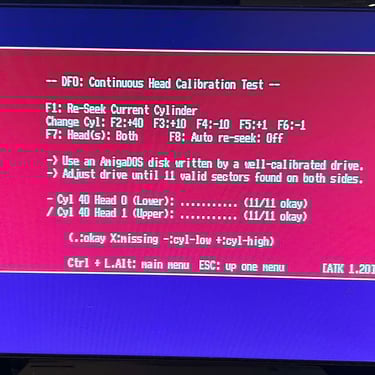
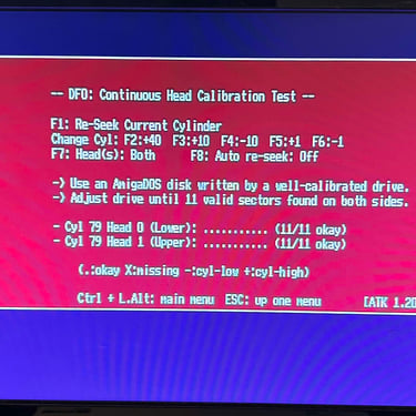
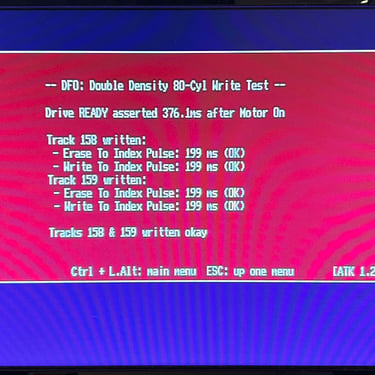
The same tests which where used initially are executed again. And as can be seen from the table below all tests pass.

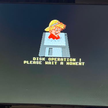
Below is a video and some pictures from the testing.


Banner picture credits: Medvedev