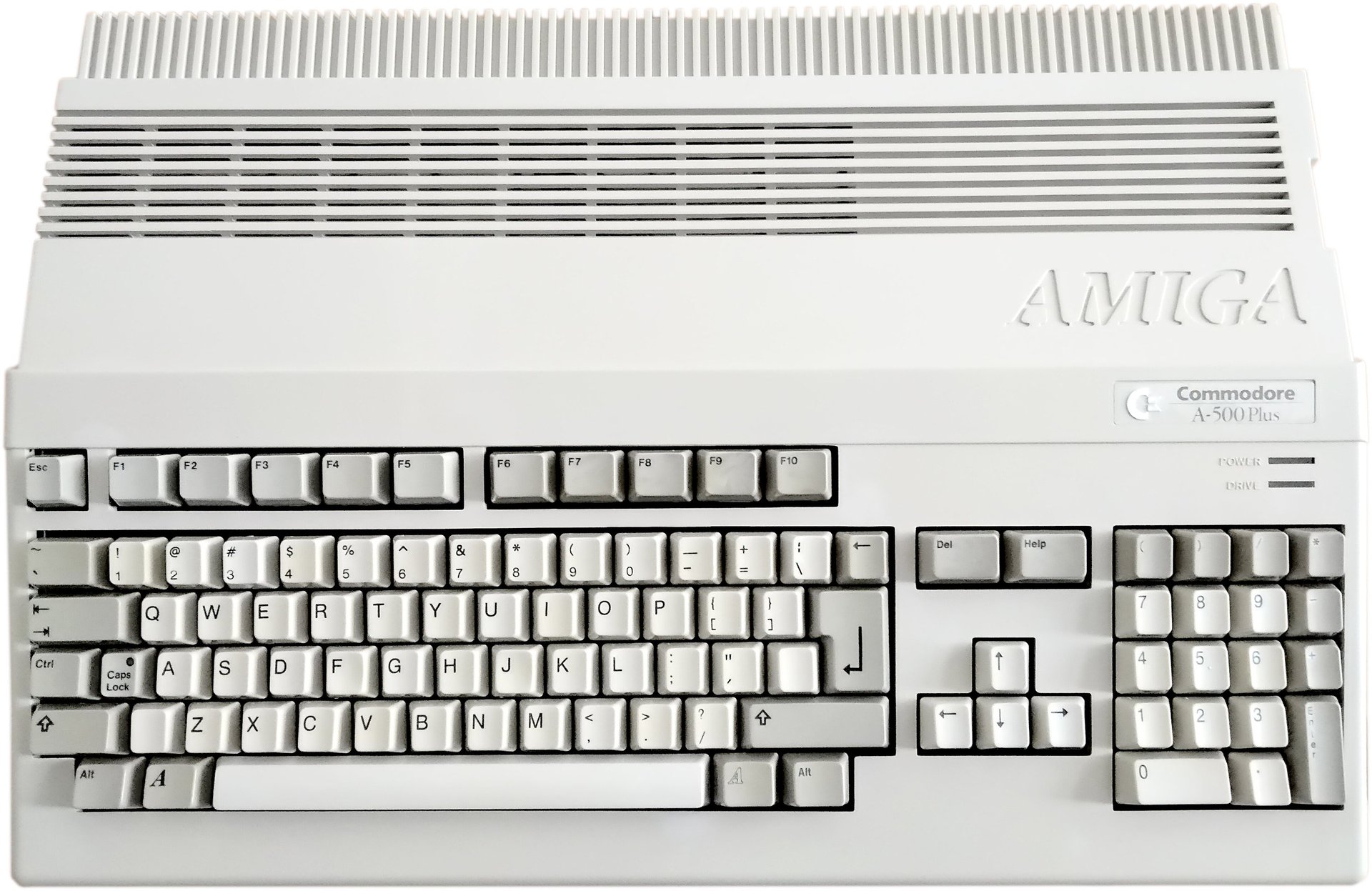
Amiga 500 Plus
Ser. No. 009062
Assy 312812
Artwork 312815 REV 8A
Starting point
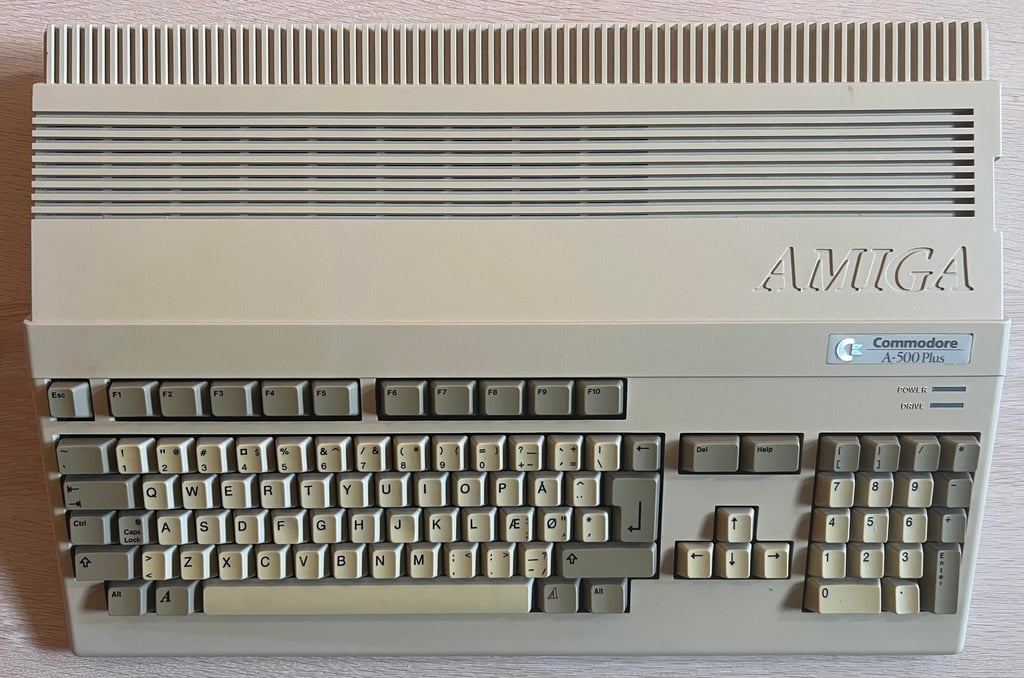
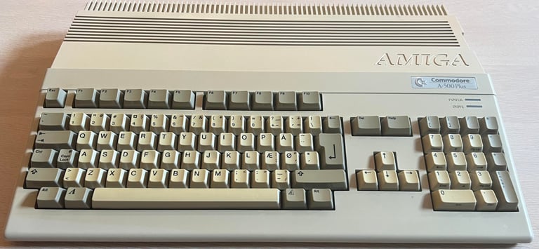
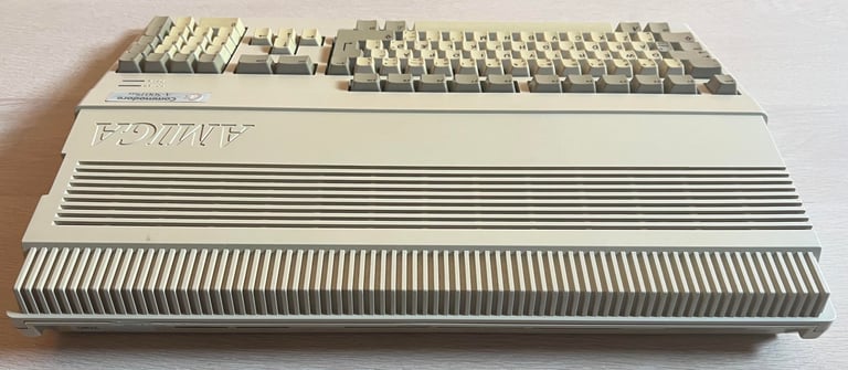
This is a very good looking Amiga 500 Plus. It is slightly yellowed, but aside from that it looks very nice. Also, it is expected to be in working condition except for two issues:
Battery leakage inside
Not all the keys are registering all of the keypresses
Luckily the owner of this Amiga 500 Plus has removed the RTC battery already, but the problem with battery leakage (or capacitor leakage for that matter) is that if the leakage is not properly removed it will expand further into the mainboard. Eventually it will corrode and damage traces, pads and ICs.
Removing the leakage in itself is not the most challenging operation (yes, it takes quite some time and effort), but it is not uncommon that the removal of the leakage will provoke damages. If traces are working, even if they are covered in leakage, it is not uncommon that when removing the leakage the trace will break using tools such as a fiber glass pen. This breakage would happen eventually anyway, but the cleaning would provoke it. So in short; the refurbishment of this machine will primarily be focused on carefully removing (and possibly repair or strengthen some traces) the battery leakage.
Retrobrighting and changing the capacitors will also be done after the mainboard is refurbished.
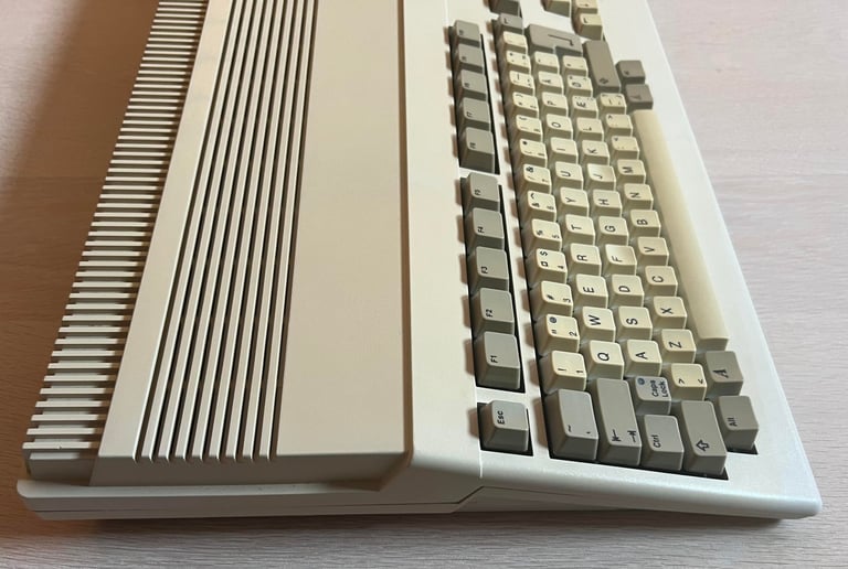
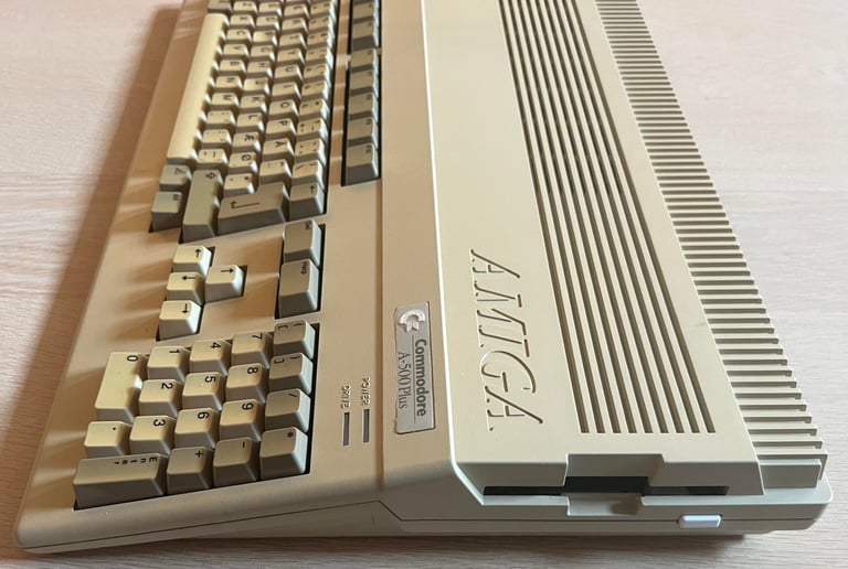
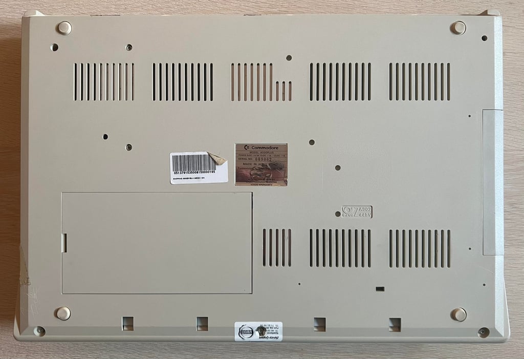
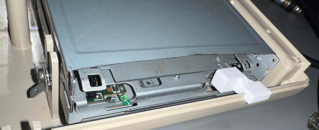
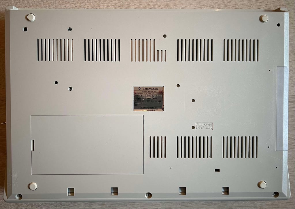
Below are some pictures of the Amiga 500 Plus before refurbishment. Notice the original Commodore warranty seal is replaced with a Danish Service sticker. This machine is maybe used in Denmark - and repaired in Denmark at some time? Also, notice the very white colour on the disk eject button. I am not sure if this is an original disk drive, but I think that it might not be (the owner inform me that this is a modified PC drive with a 3D printed eject button).






Refurbishment plan
To refurbish this Amiga 500 Plus the plan is to do this trough the following steps (some of them in parallell):
- Clean and restore the keyboard
- Clean and remove stains from the exterior top- and bottom cover
- Retrobrighting keyboard and covers
- Refurbish the main board (cleaning, checking, repairing, replacing capacitors etc.)
- Install DF0/DF1 boot selector
- Verify operation by testing
NOTE: The refurbishment of the disk drive will be done separately.
Disassembly
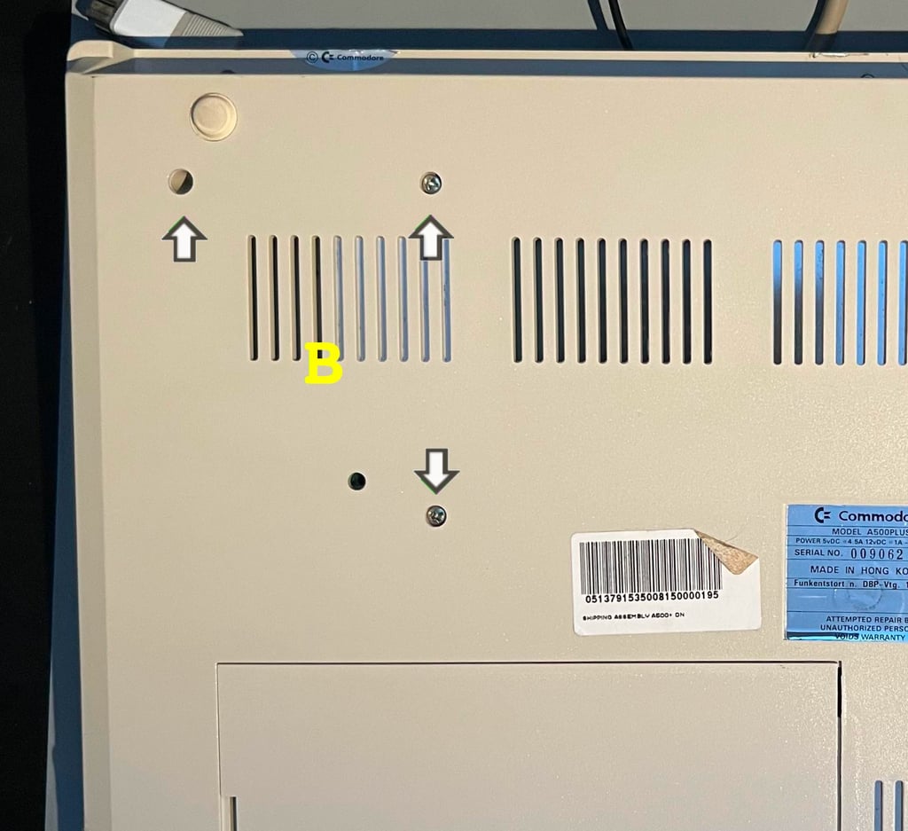
To open the Amiga the six screws at the bottom cover are removed. These are T3 torx 10 mm screws. Notice to not remove the other screws as these will hold the disk drive in place.
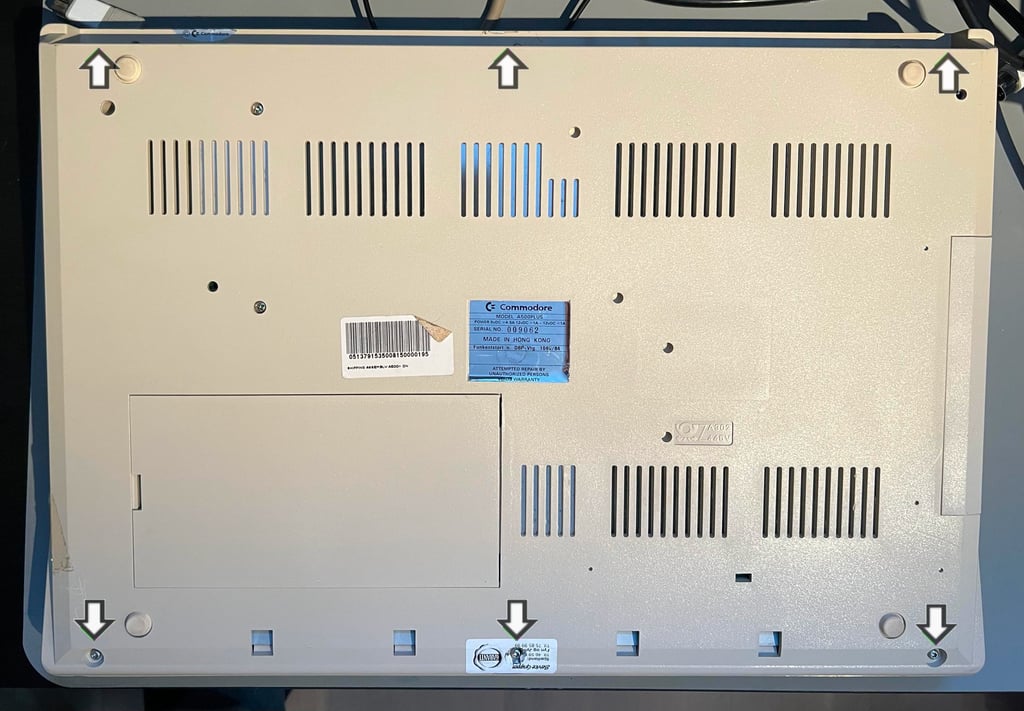

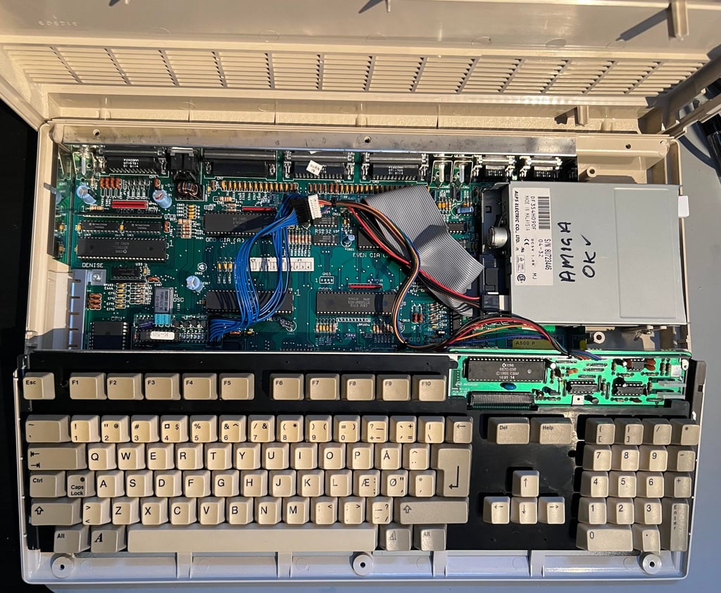
The top cover is carefully lifted while pushing gently on the clips which are located on both sides just above the top of the keyboard. First impression is very good. It appears to be in very good condition. Almost no dust and grease! Instead of having the keyboard connector directly coupled to the motherboard the connector is mounted on something which I believe is a ROM (Kickstart) switcher. Also, I can now see the internal disk drive which is a modified PC disk drive. The drive is an ALPS drive which should be a good drive (at least I have good experience with these from older 1541 disk drives for the Commodore 64). I also notice that there are no RF-shield covering the mainboard. Whether or not this is removed by a previous owner or not I am not really sure. Anyway, it does not matter as these RF-shields are not required in modern age.

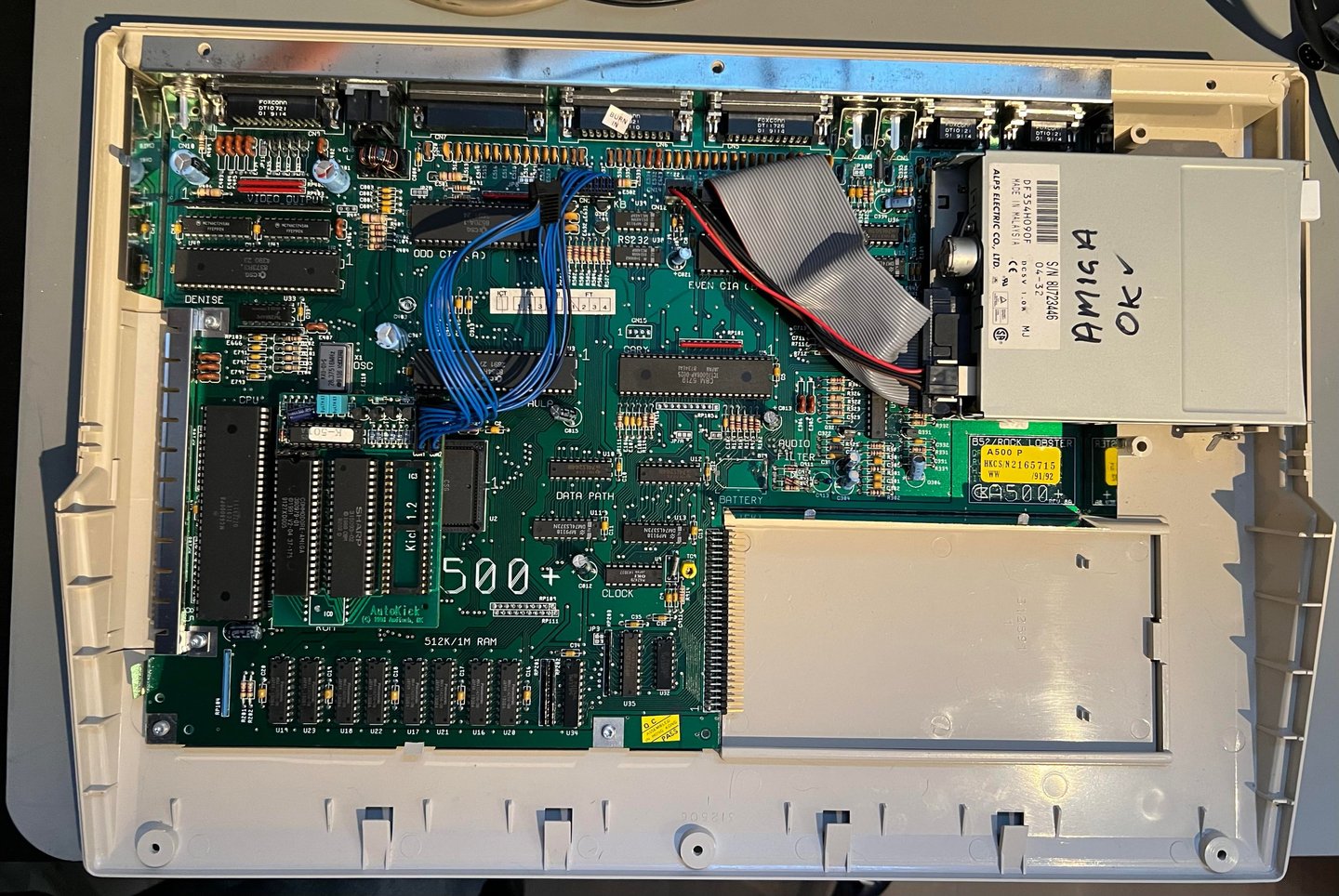
The keyboard connector is detached from the blue cable and then the whole keyboard is lifted away. Now the ROM Kickstart switcher is revealed in all its glory! Also, I get a first glimpse of the leakage damage in the RTC battery area and it does not look too bad! Nice!

Next point of action is to remove the disk drive. This is not complicated, but I do this in three steps to avoid any damage:
Remove the disk drive power- and I/O connector from the mainboard marked CN12 and CN11 (FLOPPY) respectively
Remove the screw on the right hand side of the disk drive (as seen from above) - see picture with marking "A"
While the bottom cover is shifted slightly off the table, the three remaining screws at the bottom cover are removed from underneath. You might need to bend you head in order to see the screws, but removing the screws without turning the bottom cover upside down prevents the disk drive from falling out.
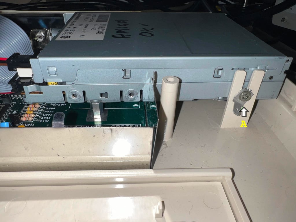


Now the 3D printed eject button is also exposed. It looks very well, but I notice that it is laying slightly low in the chassis. If the drive is OK (or if I can salvage it) I will try to add three 1 mm spacers to lift the drive slightly.

With the disk drive out of the way it is time to remove the PCB from the bottom cover. These are also T3 torx screws (four of them), but they are smaller than the T3 torx screws holding the top- and bottom cover. The torx screws holding the PCB are only 7 mm long. It is good practice to keep the screws in separate bags to avoid damaging the standoffs when re-assembling the machine. Below is a picture of the mainboard and bottom cover with the disk drive removed, and the position of the four T3 torx screws are indicated.
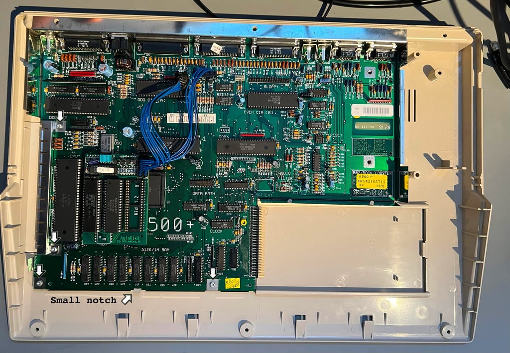

The whole mainboard PCB (with the bottom metal shield) is gently wiggled out of the bottom cover. Note that there is a small plastic notch holding the PCB in place also. This small notch can easily break since the plastic is old and brittle (not the end of the world though...). Finally the 12 hex head bolts at the end are removed (H5 screwdriver).


Exterior casing
As mentioned in the introduction the covers looks very good. Yes, there are some dust, grease and tape residue, but not much. The "biggest" thing is that the covers are slightly yellowed. The yellowing is not severe at all, but I think it is worth a retrobright.
Before retrobrighting it is crucial that the covers are properly cleaned. To make sure this is the case the top- and bottom covers are soaked in mild soap water for about 48 hours. Note that the four rubber feets are also removed - retrobrighting these will make the rubber feets like... melted rubber!
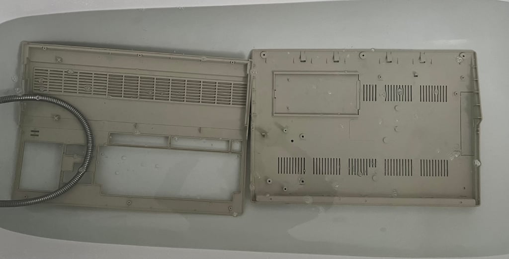

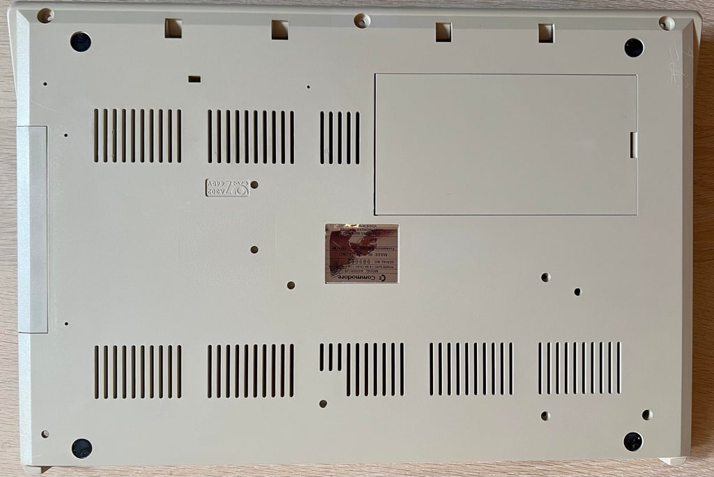
After this long bath most of the dust and grease is gone. But there are still significant marks which needs to be removed with isopropanol. Luckily, these are easy to get rid of. See pictures below.


Both the broken warranty seal and scan code is removed. The casing looks quite good now. It is still quite yellowed, but it looks much better already. Below are some pictures of the covers before retrobrighting.
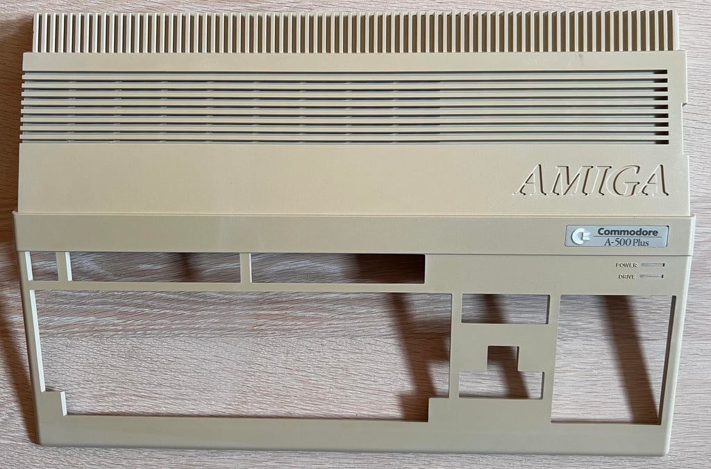


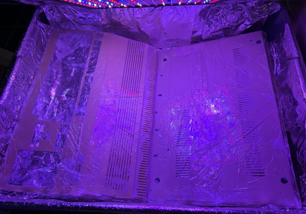
The covers are retrobrighted for about 14 hours using 12 % hydrogen peroxide and UV light.

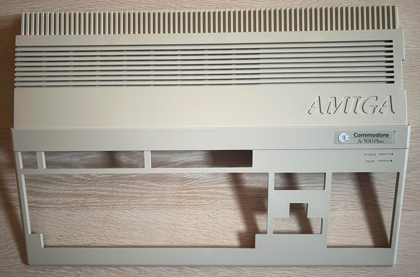
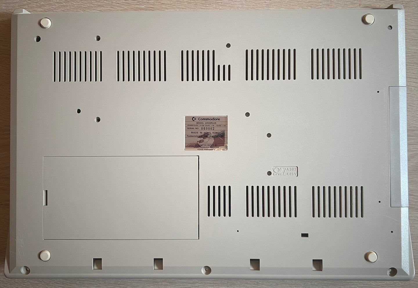
After retrobrighting the covers looks way better I think. There is still some very slight yellowing, but it is much better. Since the retrobrighting process is such an agressive method to the plastic I choose to stop here not do damage the plastic.


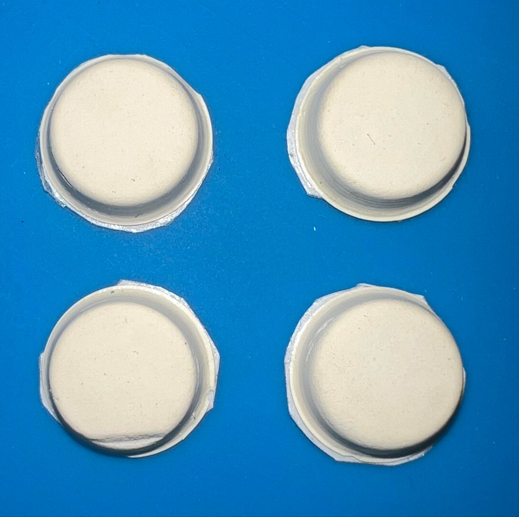
Finally the four rubber feet are cleaned with some isopropanol and Q-tip. Beneath each rubber feet is a small patch of double sided tape.

Keyboard
The keyboard is reported to be only partially functioning. The owner reports that the large "0" on the right hand side keypad is not registering any keypress when being pushed. Faults on old Amiga keyboards is quite common and usually caused by:
Damaged keyboard membrane. The thin, flexible, keyboard membrane is notorious for failing either due to breakage or corrosion on the very thin traces.
Faulty key plungers. Each key has a plunger equipped with conductive rubber. These can get dirty and/or fail with the result that the resistance given by the conductive rubber is too high.
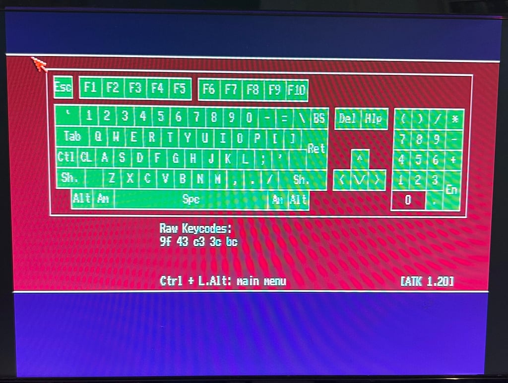
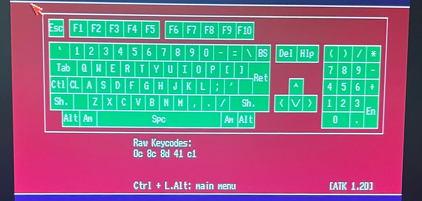
To verify that I can reproduce the fault the keyboard is tested with Amiga Test Kit (v1.20). As can be seen from the picture below the "0" (Zero) key does not register any response while being pressed. Also, the "O" (the letter, not the number) is a bit suspicious - feels hard to push.

Keyboard teardown
To repair the keyboard it needs to be completely disassembled. But the Amiga keyboard membrane is very fragile and can easily break in the process so it is recommended to be careful.
First all the keycaps are removed. This is done by using a keycap puller. The keycap puller reduces the risk of breaking the plungers and/or damaging the keycaps..
This is how I teardown the rest of the keyboard:
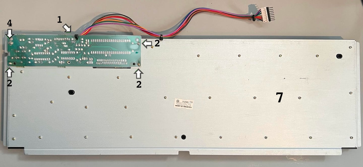
STEP 1: The small cable tie which function as a strain relief is cut
STEP 2: The three screws which are holding the PCB plastic insulation are removed. Note that these three are screwed over the plastic insulation.
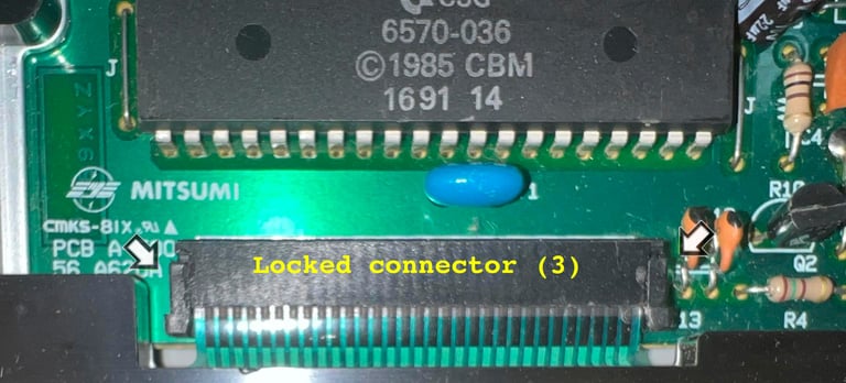
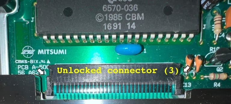
STEP 3: The keyboard is turned around and the keyboard connector is loosened by carefully pushing the two sides of the connector downwards.
STEP 4: The keyboard is turned back round and the fourth screw holding the PCB is removed. Note that this screw is placed under the plastic insulation.
STEP 5: The keyboard is flipped around again and the PCB is now CAREFULLY wiggled loose from the keyboard connector.
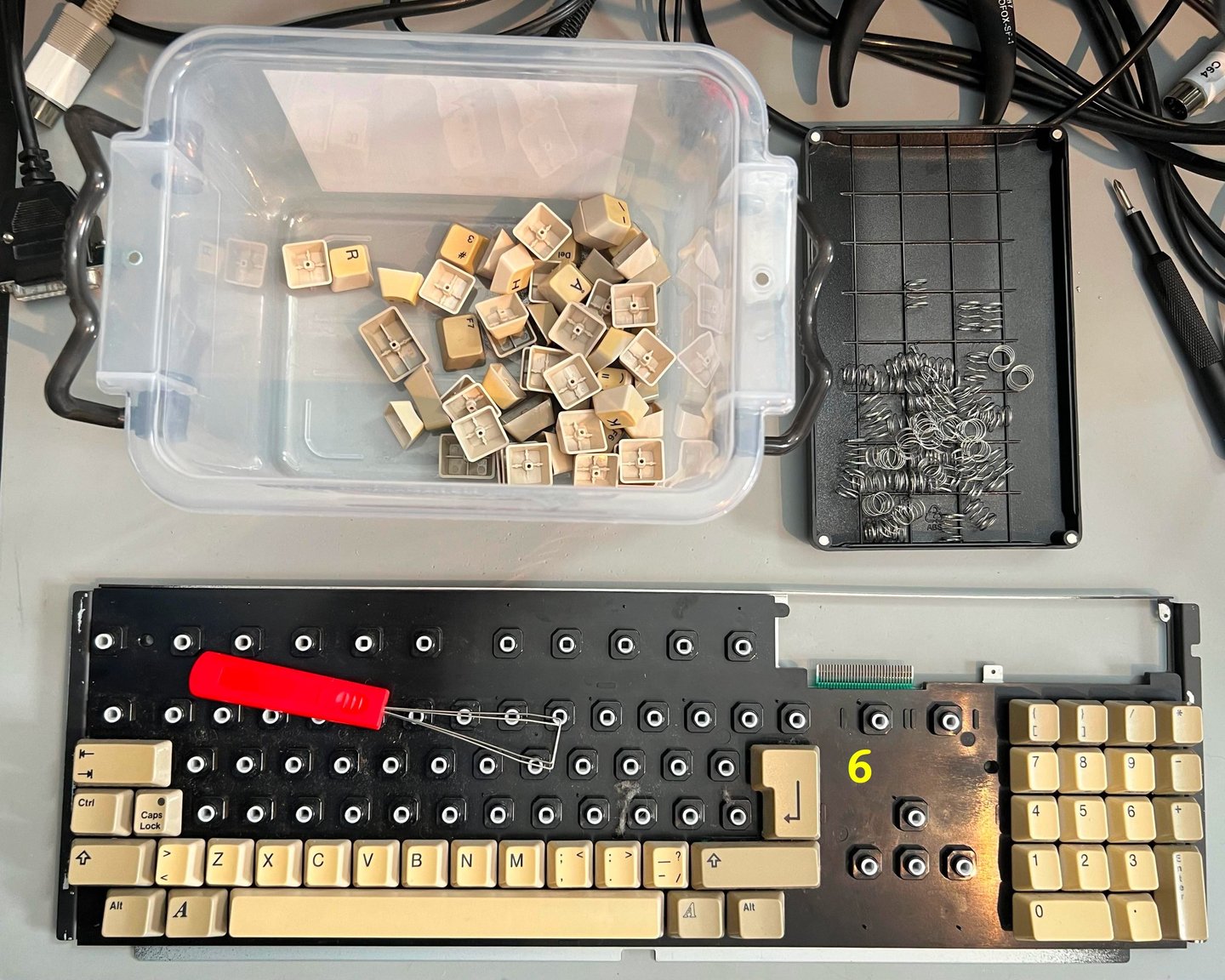
STEP 6: All the keycaps are removed.
STEP 7: All the remaining screws are removed from the back of keyboard.
Below are some pictures showing the locations of these steps.




Visual inspection
There are no obvious, and visible, damage related to the "0" (zero) key beneath the keycap. The plunger is present and appear undamaged. See picture below.
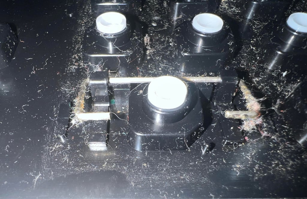

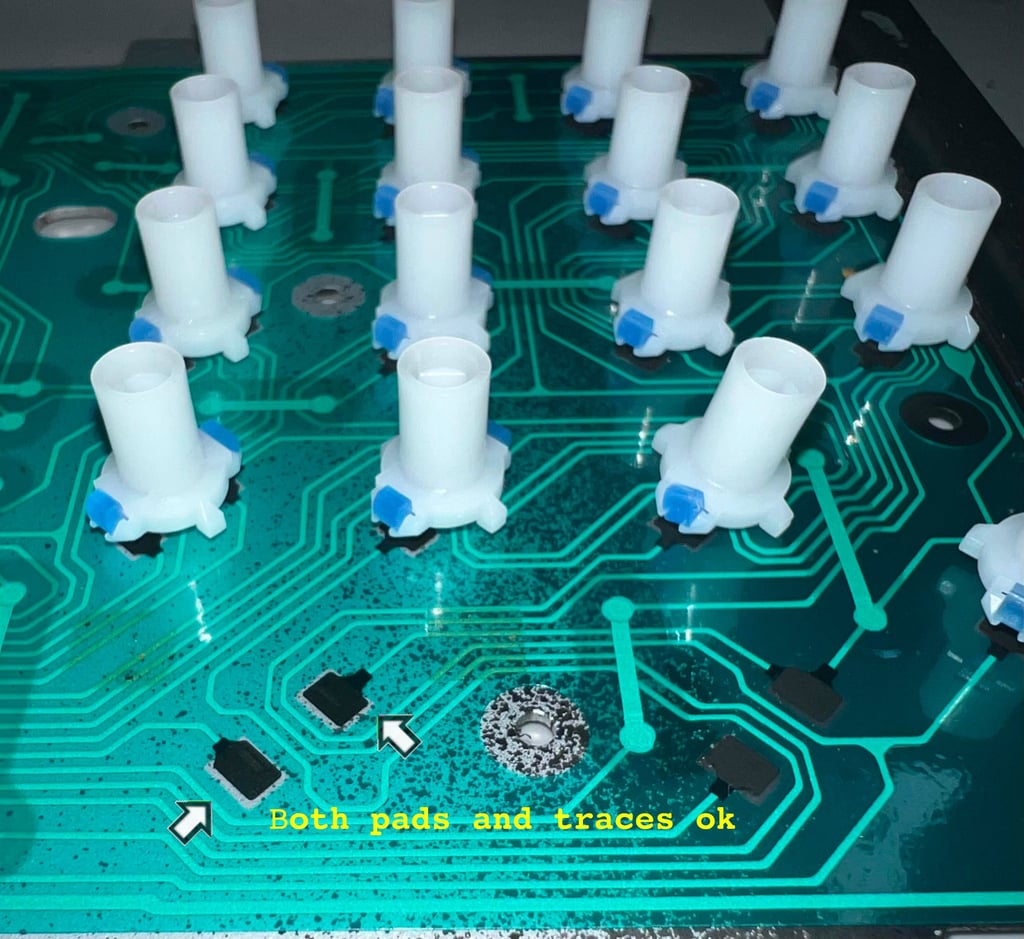
When the top plastic bracket is removed all the plungers are revealed. Still, the "0" plunger appear to be complete and undamaged. There are some square areas of grease which might have corroded the trace beneath (why are these areas of grease squares? I have no idea...). See picture below for the plunger and these square areas of grease.
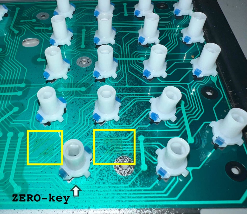

To check if the grease and dirt have corroded and damaged the traces the multimeter is set in "Ohm" mode and the resistance from the "Zero" pads are measured to different places on the membrane. The measured resistance is not zero (in the range of 150-200), but it is definitely not broken.

Repair
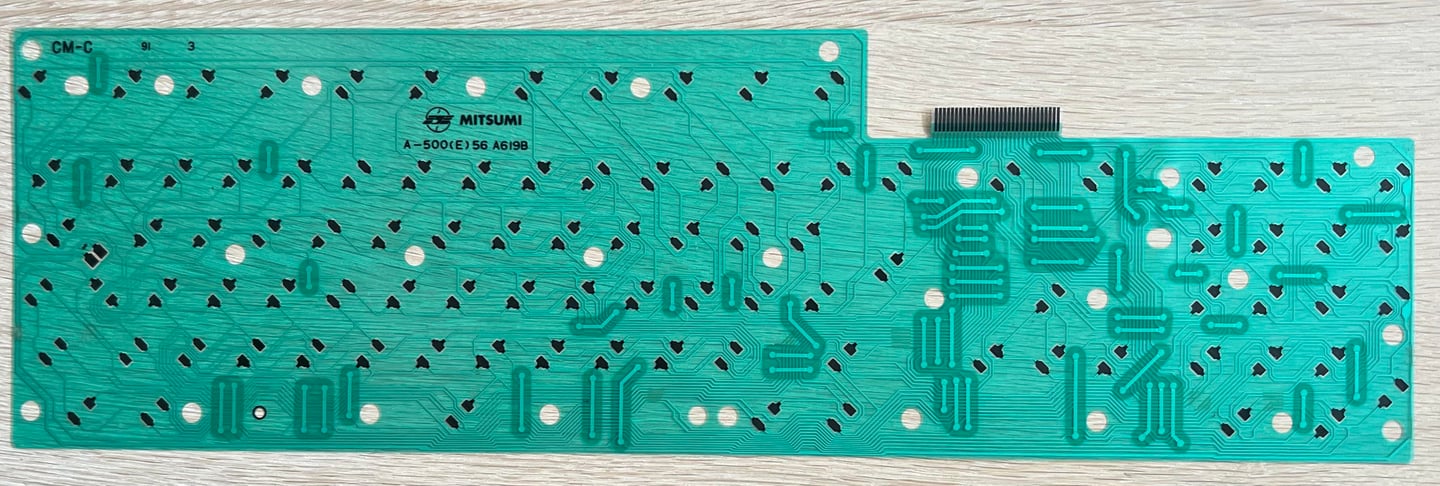
So far, the hypothesis is that the membrane itself is working. First action in the repair attempt is to clean parts of the membrane carefully with some distilled water. Since the membrane is fragile not the whole membrane is cleaned, but only those areas where the grease is present. Note that also after cleaning the square discoloured areas are still there. I have no idea what these are. This is a standard Mitsumi A-500 (E)56 A619B membrane.

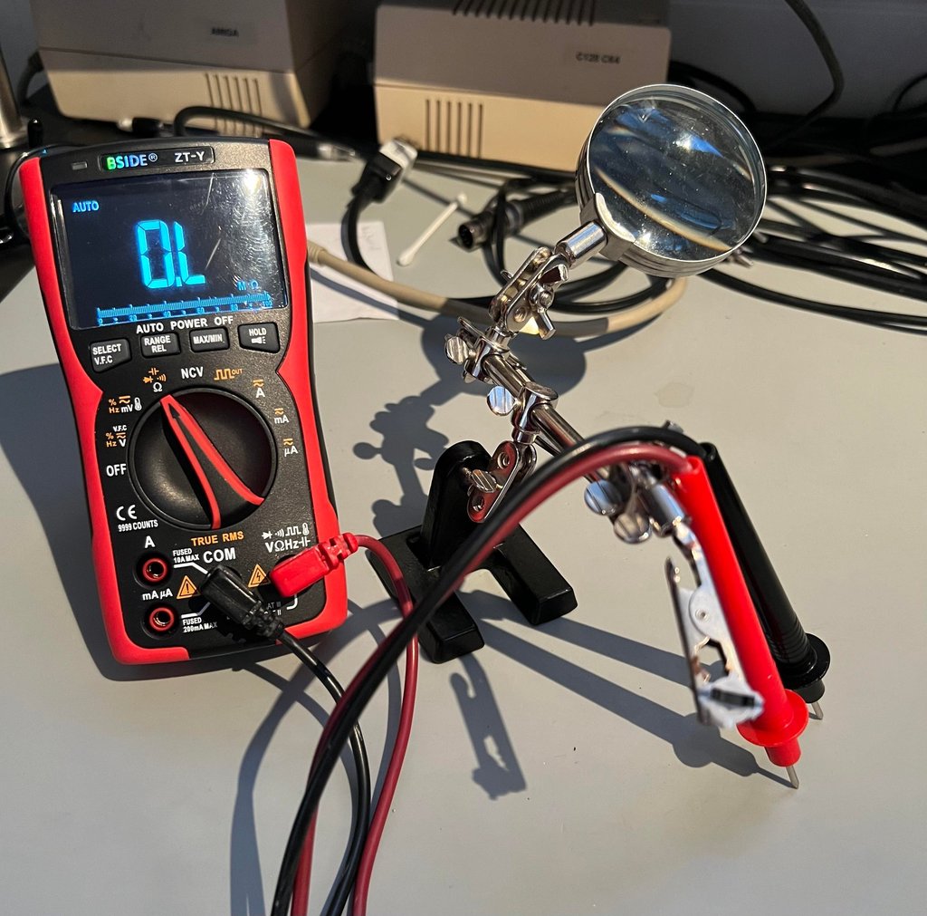
The plungers used for the key "0" (zero) and "O" (the letter) shows a measured resistance in the multiple 2-3 kOhm range which is too high. It is not trivial to measure these exactly, but as can be seen from the picture below the plungers are fastened and measured. The conductive rubber in the plungers should be in the range of 100-200 Ohms measured this way.

Two new plungers are installed and the keyboard is re-assembled (note that the keycaps have not yet been cleaned and retrobrighted - so they will be mounted later).
Cleaning and retrobrighting
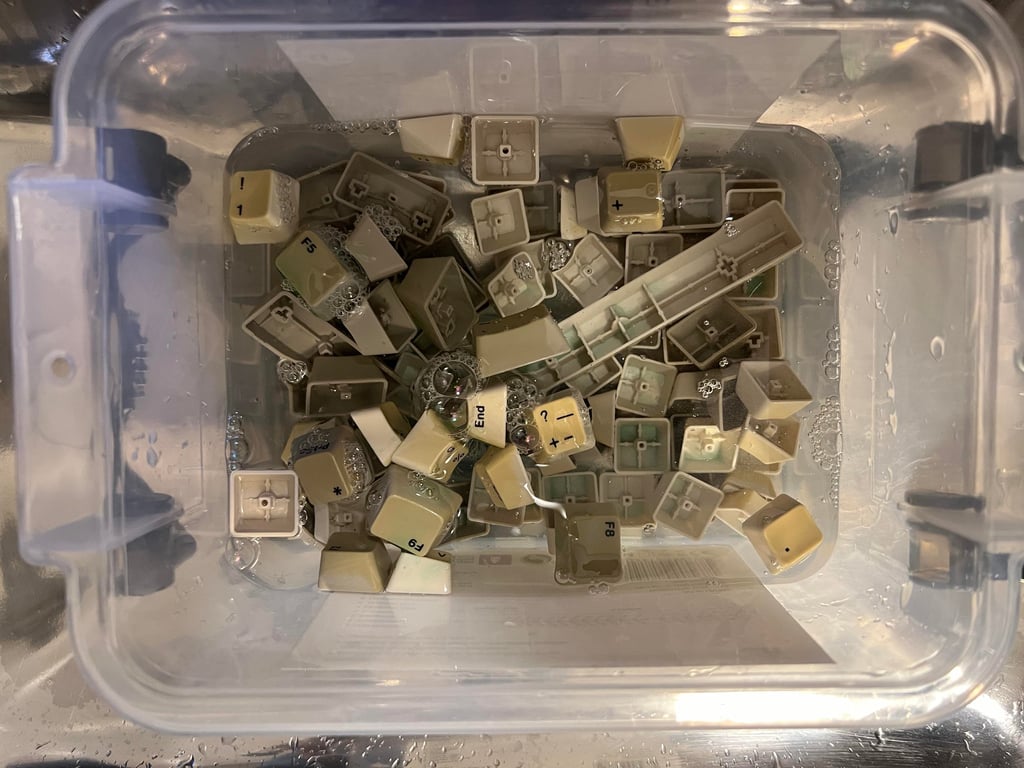
The keycaps are quite yellowed. But before they can be retrobrighted they need to be cleaned properly. All the keycaps are placed in a box filled with mild soap water for about 48 hours. This will remove most of the fat and grease.

To make sure that all the keycaps are retrobrighted the best possible way, the keycaps are placed on two 3D printed brackets. The 3D files can be found on Thingiverse.
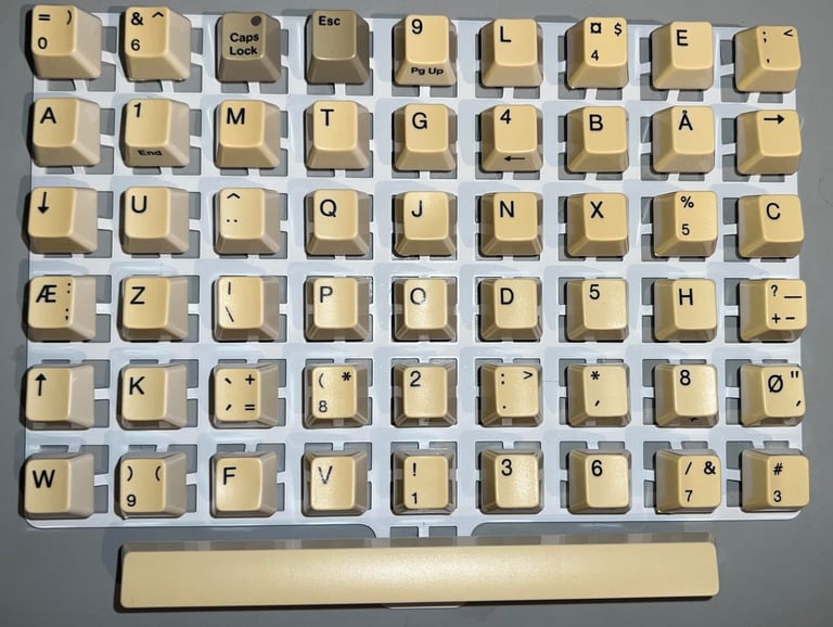

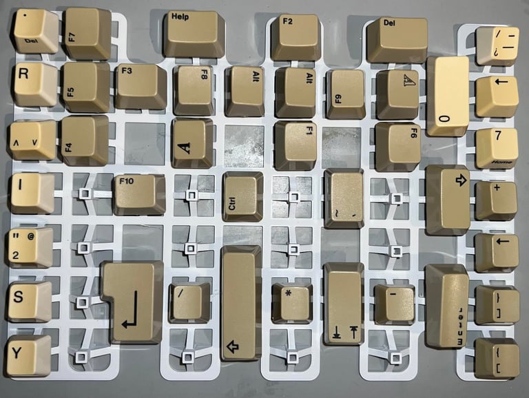

The keycaps are covered in 12 % hydrogen peroxide cream, and exposed for UV light, for about 12 hours straight. More hydrogen peroxide cream is added frequently to avoid the cream to dry out. Notice that the keycaps are also covered in plastic film to avoid drying out making marbling effects.
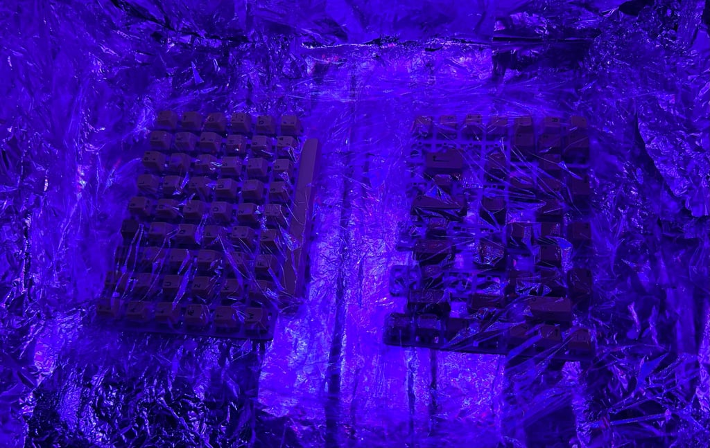

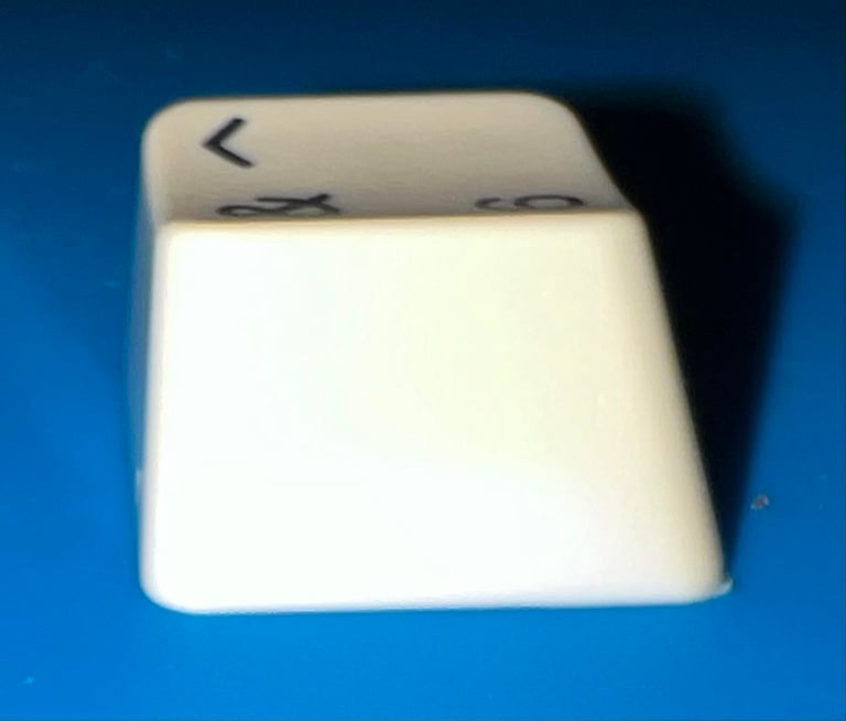
After the retrobrighting there is still some yellow residue in the keycaps, but I think it is wise to stop the process here. As with the retrobrighting the covers this process is quite aggressive (which you can feel if you get the hydrogen peroxide cream on your fingers). But I think the result is quite good! They look so much better! Below are some "before" (left/top)) and "after" (right/bottom) pictures.
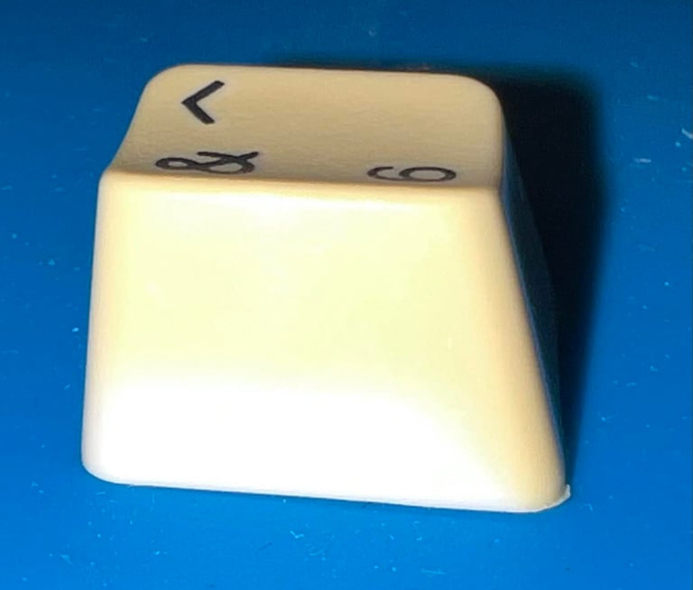


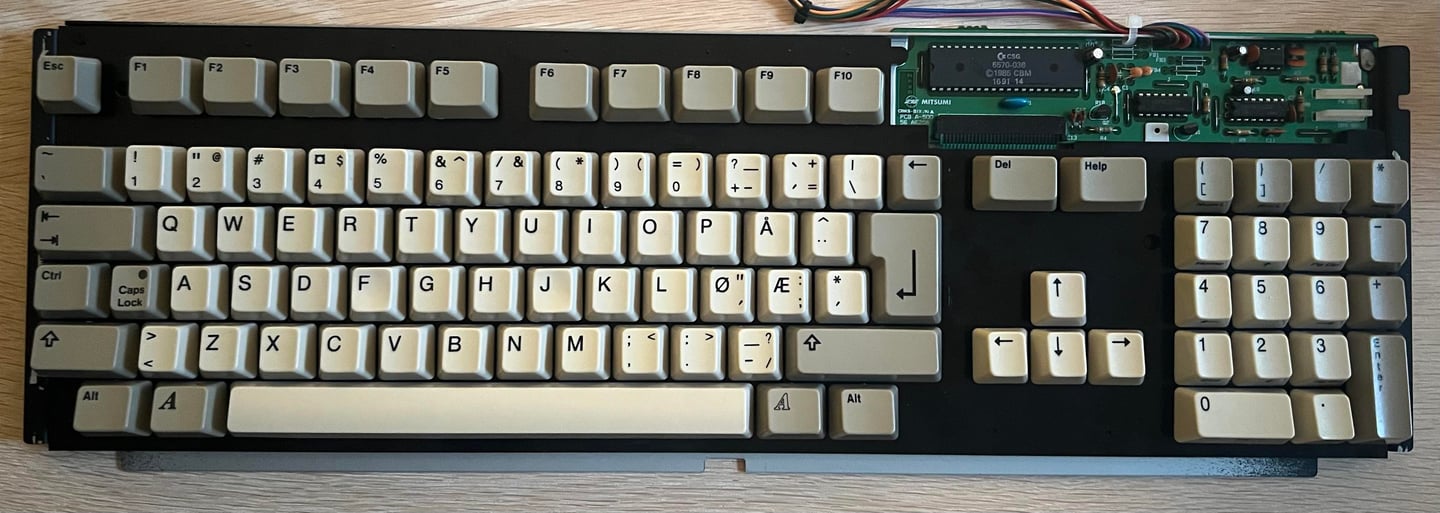
All the keycaps are mounted back on the keyboard. Looks very good I think!

The machine will be tested completely at a later stage, but I do a quick check to see if both the "0" (number) and "O" (letter) now works as they should. And using the Amiga Test Kit software all keys now seems to work just fine.

Mainboard
Visual inspection
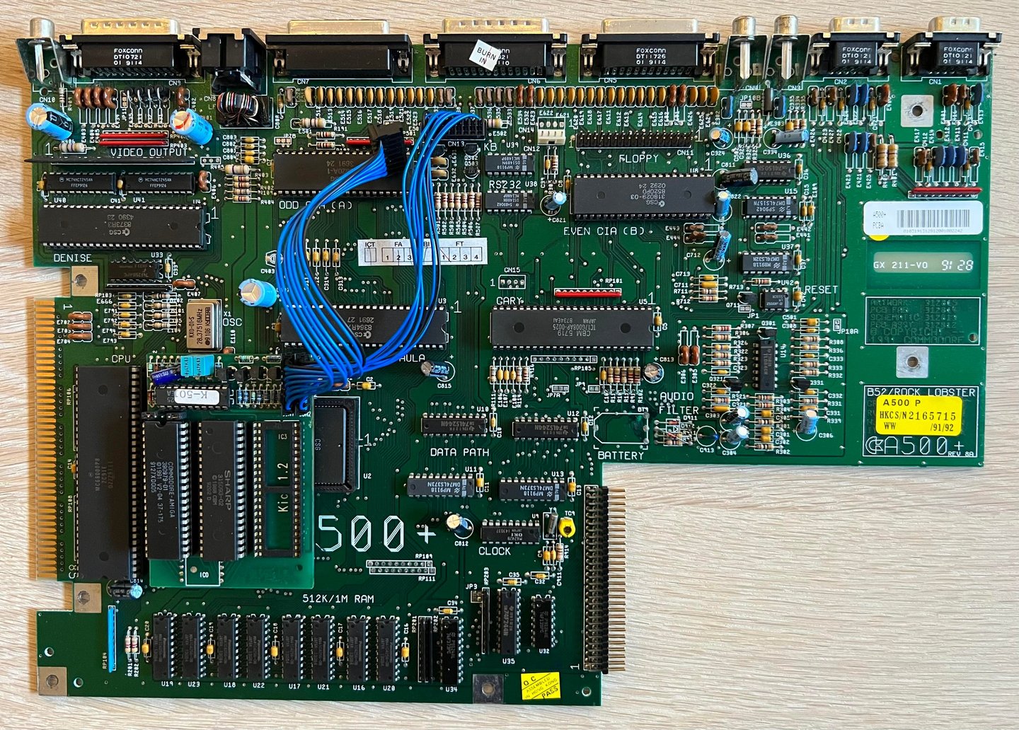
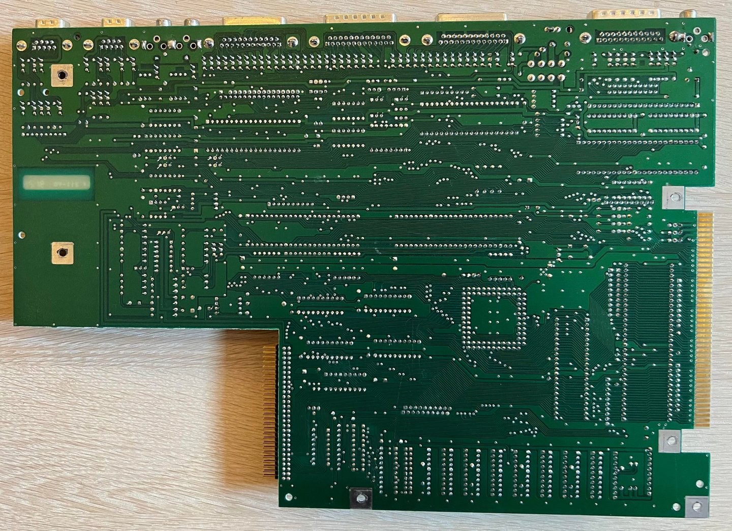
This is mainboard is labeled PCB ASSY 312812/SCHEMATIC 312813/PCB FAB 312814/ARTWORK 312815 REV 8A. It is expected to have some battery leakage, but otherwise I must say that this mainboard is in very good condition. There are almost no sign of dust inside, no sign of rework and no bulging capacitors. See picture of the pre-refurbished mainboard below.
Notice that there is an aftermarket Kickstart ROM selector installed on the mainboard. The selector is marked "AutoKick (C) 1992 AmiTech, DK". Apparently, this selector/switch has room for three Kickstart ROMs (in 1991 these were 1.2, 1.3 and 2.04), but the 1.2 Kickstart is missing.


Visual inspection - battery leakage
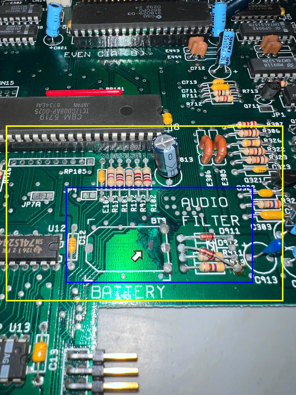
Luckily the owner of the A500+ was wise to cut out the Varta battery powering the real time clock (RTC). Most (all?) of these old Varta batteries leak after many years in storage, and the leakage can cause havoc to the mainboard. There is without any doubt leakage on the mainboard which has caused some damage, but I must say that this does not look bad at all at first glance. In the picture below the area where the battery has leaked is shown.
Notice that in the picture that the leakage area is divided in three prioritised areas. These inner area (marked with an arrow) is where the rear of the battery has been and leaked directly. The mid area (blue square) marks where it is likely that the leakage has propagated and must be inspected very carefully. The yellow area is the outer area where is still very possible that there are sign of leakage / corrosion, but it should also be where I expect the leakage to have stopped.

All the custom ICs are listed in the table below. I find it a bit hard to guess when this machine was manufactured. Most of the ICs have a date code around late summer of 1991, but some ICs deviate: the Denise chip has a date code from 1990 and the even CIA chip has a date code from vinter 1992 (in addition this CIA chip is different from the odd CIA). From the Commodore 64 era Commodore was known for "using whatever was available" of components. If this tradition was continued also in the Amiga age it is not impossible that this machine could be manufactured some time early in 1992. If the even CIA was replaced due to a later malfunction my guess would be that the Amiga 500+ was manufactured some time early autumn or late summer of 1991.
Intitial testing - first power on
The machine is expected to be in working condition (except for some issues with the disk drive and the keyboard). To verify that the machine is working before refurbishment the machine is powered on before any work is started. The thing with battery leakage is that it is not unlikely that the machine stops working during the refurbish. Traces, vias and pads that are being cleaned and rinsed can often be "damaged" during the operation. But this is basically the same that would have happened at a later stage, but it is provoked by the refurbish.
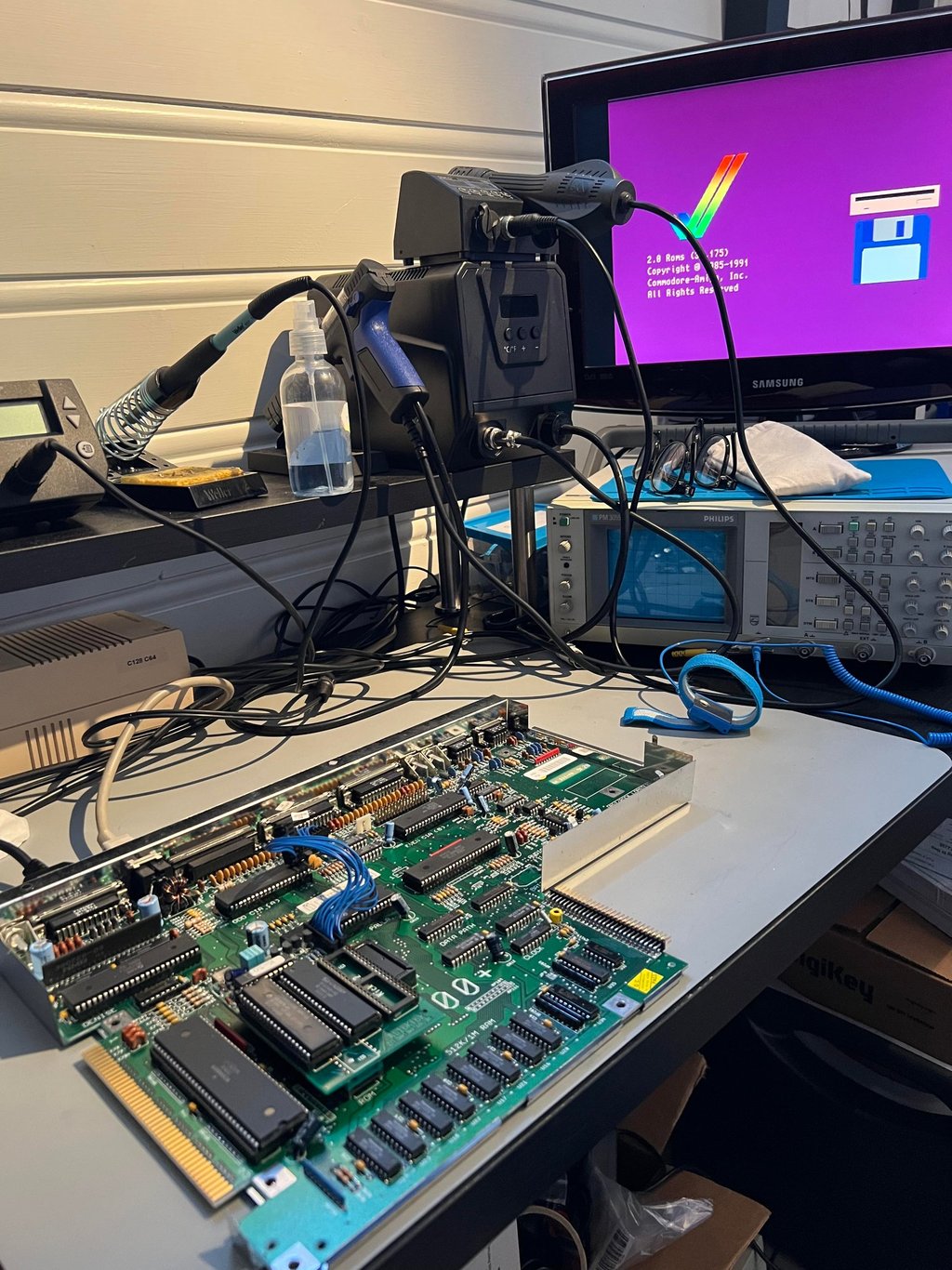
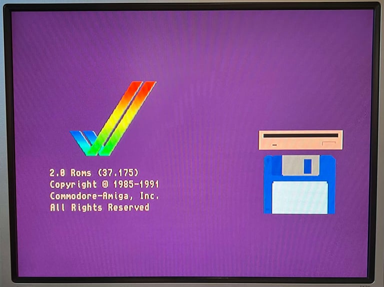
When the machine is powered on the keyboard and disk drive is disconnected. These will be tested later. As can be seen from the picture below the machine powers on without any apparent issues. Starting up with Kickstart 2.04.

Checking the voltages
Even if the machine powers on without any issues it is good practice to measure the voltages - to verify that all voltages are present and within tolerances. As the table below show all voltages are present and ok. Note that this table will be updated after completing the refurbish.
Repair - battery leakage
As mentioned previously this Amiga 500+ boots up fine and appear to be in working condition so far. But there is a battery leakage. Currently this battery leakage has not caused any immediate problem with the machine, but if it is not taken care of it will eventually. Now, the challenge with these battery leakages is that in the process of removing, and preventing further expansion of, the leakage damage may occur. When using tools such as fiberglass pens, sharp metal tools and such to remove the leakage traces and pads may be broken. So working with battery leakage damage can be both tedious and frustrating - but this is also part of what makes it a nice challenge.
The way I address battery leakage is:
With a thin sharp metal tool (tip point) the area exposed of the leakage is scraped. Note that I do this before I do anything else. I do this to get a good "feel" on where the leakage and damage is. Its almost as scraping paint of an old house. You get a "feel" on where the damage is and you have visual on where the the damage is.
Some diluted vinegar is applied on the area with a soft tooth brush for about 5 minutes. Since the vinegar will neutralise the battery leakage very tiny bubbles appear in the liquid. With close inspection during this process you will also see areas where no bubbles are visible. This is basically the area where the leakage has not reach. This might sound very easy, but it is not very easy to detect so there is always some room for error.
After the 5 minutes the vinegar area is cleaned properly with isopropanol. This point needs to be stressed, because if you dust apply the vinegar and a quick clean the vinegar will start damaging the mainboard!
The two last steps are done a repeated a few times. You will see that the amount of tiny bubbles are almost zero at the end.
All exposed copper / solder areas brushed with a fiberglass pen (and/or with metal scrape in combination). This will remove any surface corrosion.
Finally all exposed copper areas are tinned with fresh solder (using a solder wick) and covered with transparent nail polish.
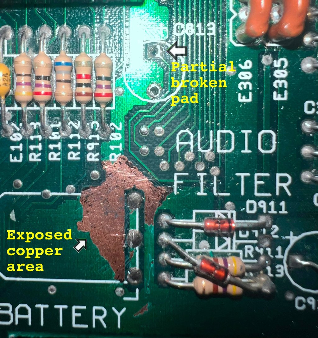
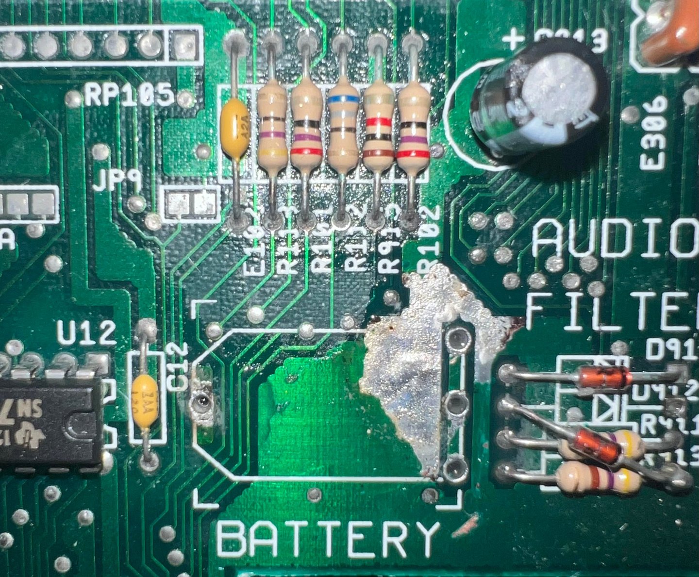
Below is a picture from the initial part of the process. The leakage area is properly scraped down to the bare metal. Note that this is also where leakage has done the "real" damage. During this part of the process the C813 capacitor is also removed to check that there is no corrosion that far away. There is a party broken pad here, but I do not think that is due to any leakage but due to a bit too high temperature on the soldering iron while removing the capacitor.

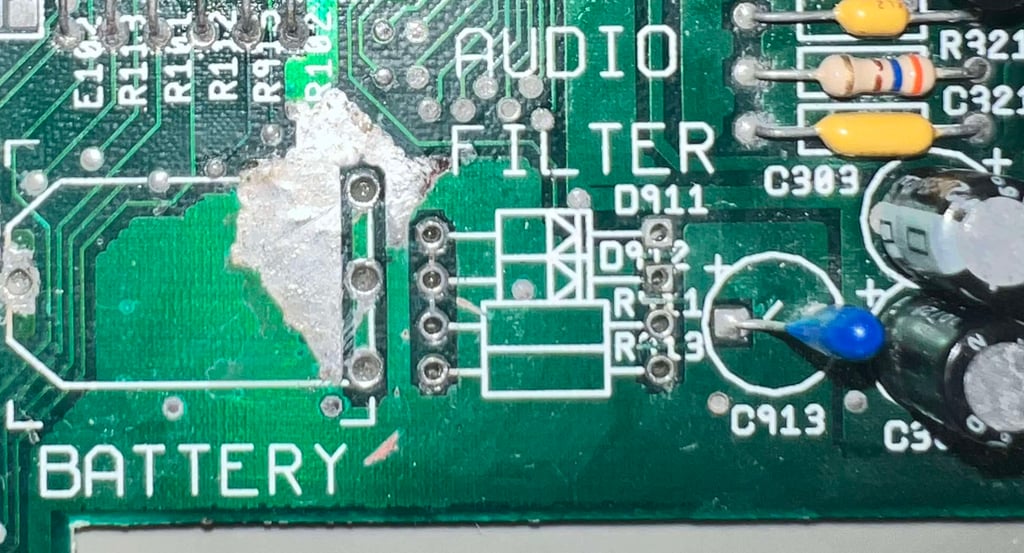
After this initial part of the process with diluted vinegar (and isopropanol for cleaning) is done repeatedly. Luckily, it is quite easy to clean this area. The vinegar and the isopropanol reaches well over/beneath all the resistor/diode network in the area. Hopefully all the leakage is now neutralised and stopped. Finally the exposed areas is tinned with solder and sealed with transparent nail polish. Below is a picture of the final area.
NOTE: It is highly recommended to open the Amiga 500+ about every 6 months to check that leakage has stopped. It is of course possible to be 100 % sure that the leakage has stopped, but with a quick visual inspection comparing the above picture this sound be an easy check.

Update:
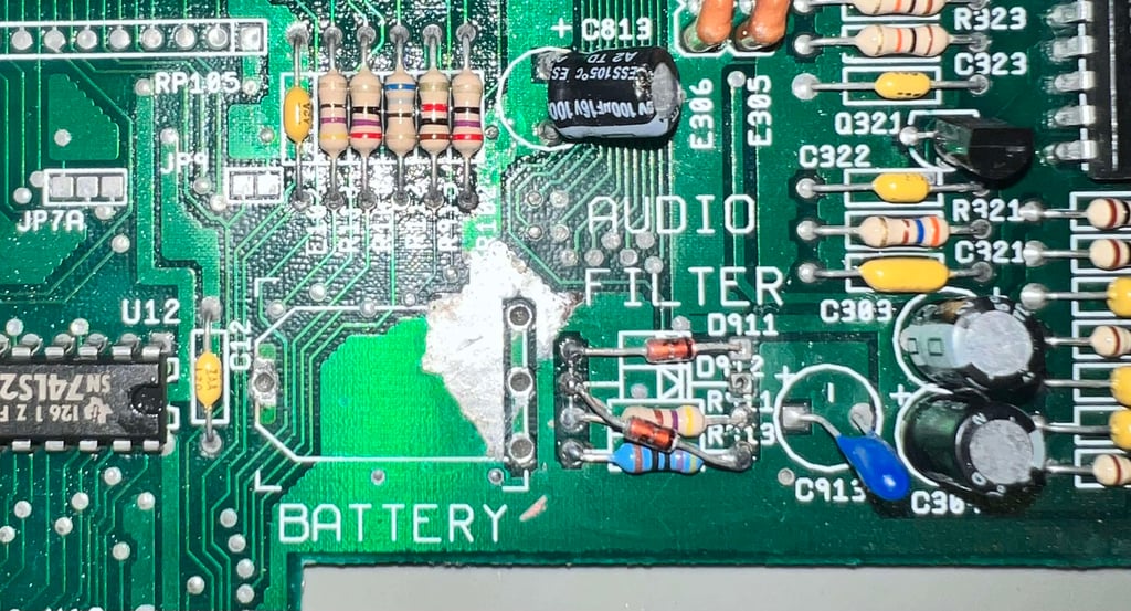
After about 6 months the machine was opened to check for corrosion. And there were some signs that some corrosion was still active. But not any major corrosion to traces or pads as I could see. This time the diode/resistor network was desoldered, cleaned and re-soldered back in. Hopefully this should do the trick.
Note that the bottom 470 Ohm resistor broke (?) during repair and was replaced. Below is a picture of the repaired area.


Replacing the electrolytic capacitors
The electrolytic capacitors are 30+ years. There are many opinions on whether or not it is necessary to re-cap these Amiga mainboards, but I think it is wise. All electrolytic capacitors will dry up eventually, and it is good practice as part of refurbishment to replace the electrolytic capacitors. According to the capacitor list there are 15 electrolytic capacitors on the assy 31812/artwork 312815 REV 8A.
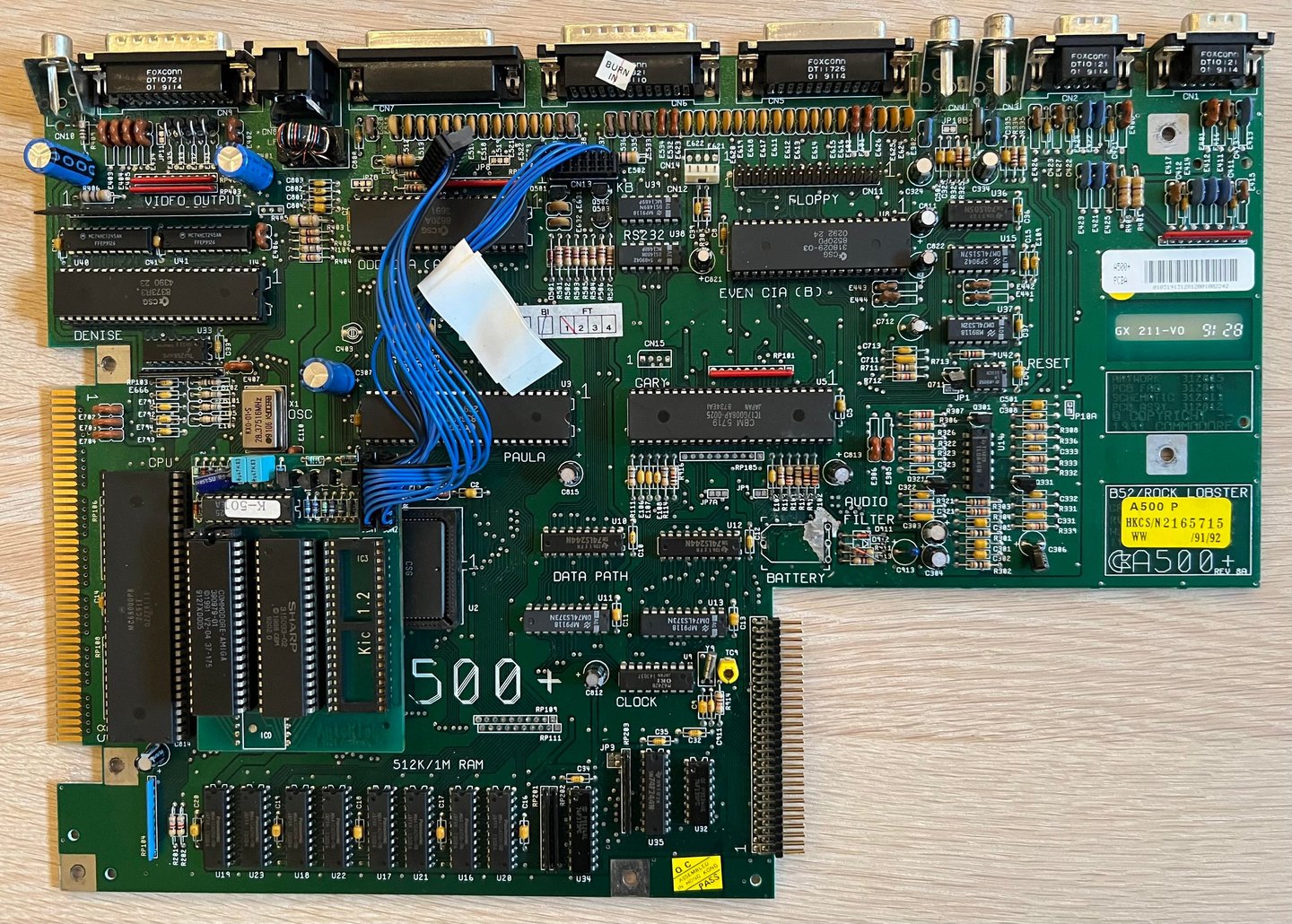
Below is a picture of the mainboard after the new capacitors are in place. Note that the capacitor C813 has a partly damaged pad as described earlier, but the trace and pad is verified ok after new capacitor is installed.


DF0/DF1 floppy drive boot selector
This Amiga 500+ will use an external Gotek drive in addition to have an original Amiga floppy drive. To be able to use the external Gotek drive as the "primary floppy drive" a DF0/DF1 switch is installed. With this switch the user can select which floppy drive to boot from; either the internal floppy or the external Gotek. The DF0/DF1 switch is sourced by the owner of the machine.
To install the DF0/DF1 floppy boot selector the EVEN CIA is removed. The boot selector is placed in the EVEN CIA socket, and then finally the CIA chip itself is placed in the boot selector PCB socket. See image gallery below.
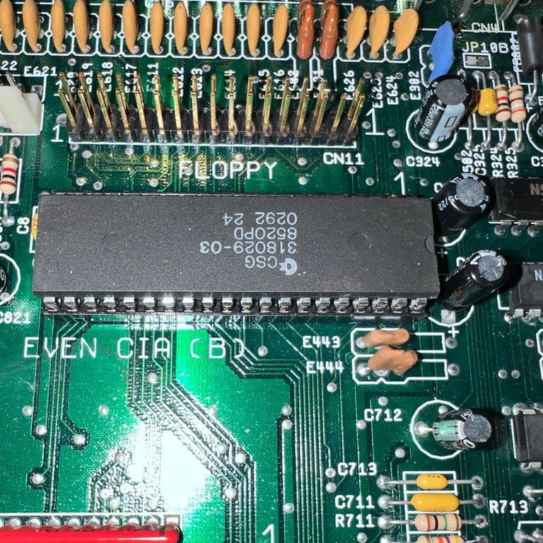
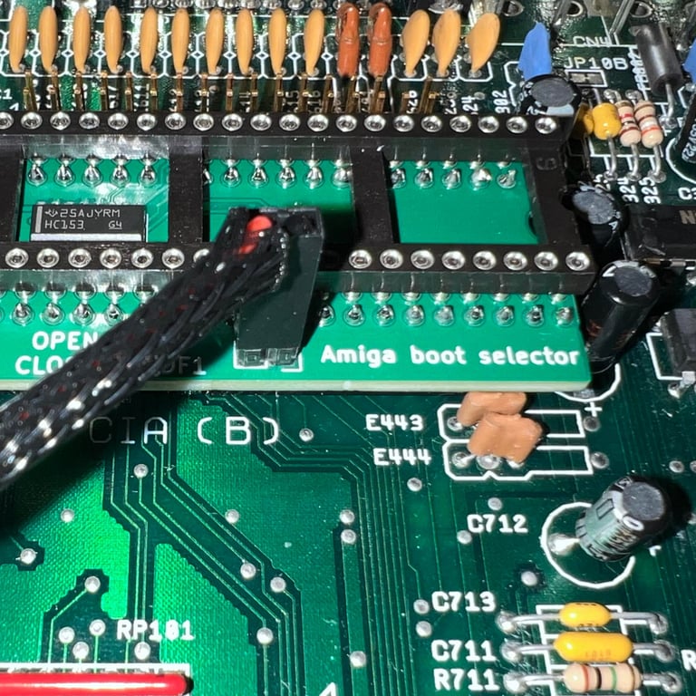
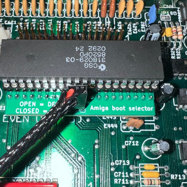
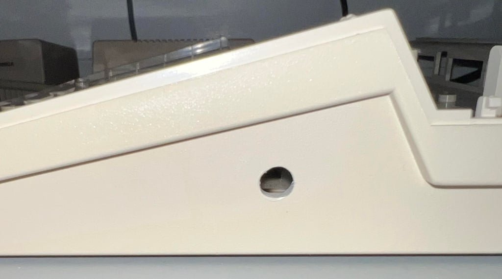
The toggle switch will be available on the right hand side and close to the user. A 6 mm hole is drilled with a 5 mm wood drill and rounded slightly. This should give a tight and good fit. See picture below.

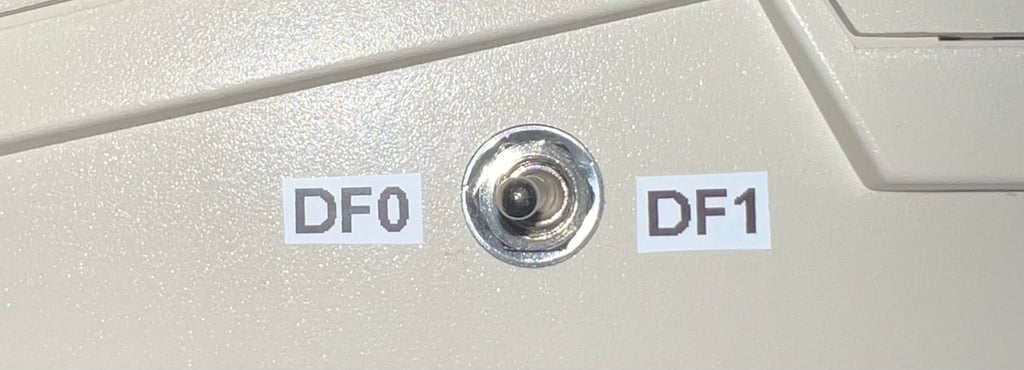
Some stickers marking which device which will boot "DF0/DF1" is placed on the bottom cover also.

Internal disk drive
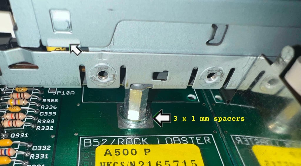
The internal disk drive is already refurbished, and modified from PC, so no need for additional work on the drive itself. Nevertheless, although not so easy to see from the pictures, the 3D printed eject button is laying a bit low in the bottom cover. As a result the tension on this 3D printed eject button, and the rest of the eject mechanism, is exposed for quite some stress since the drive is basically being held up by this button leaning towards the bottom cover. To fix this the internal disk drive is lifted 3 mm upwards.
To make sure that the 3 mm lifting is "dead rock solid" (remember that active Amiga users can be quite hard on the drives) some 3 x 1 mm metal spacers are placed in between the three feet. See picture below from one of these three.
Note that since the internal drive now is lifted 3 mm the machine screws (which were 8 mm long) are now replaced with three 11 mm screws to accommodate this change.

Testing
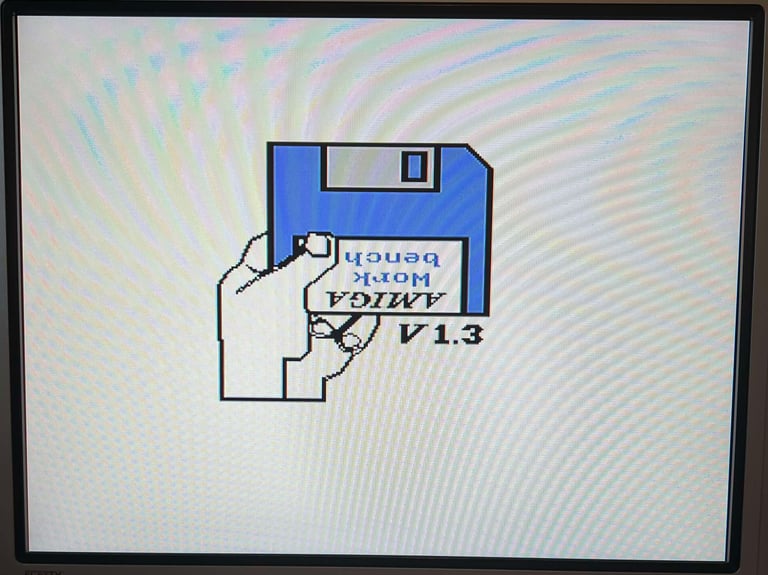
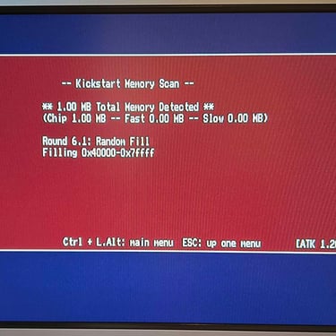
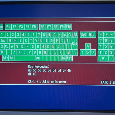
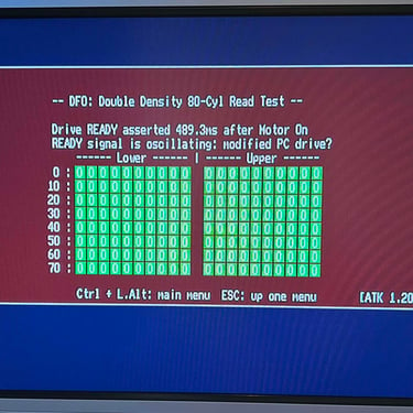
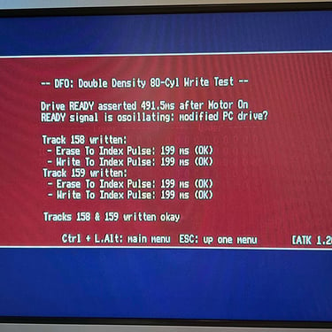
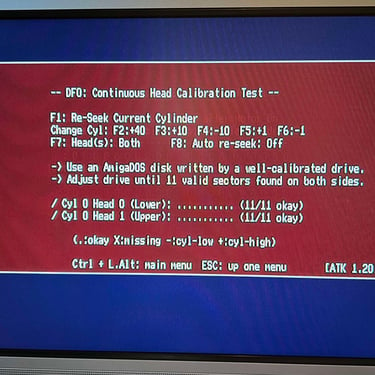
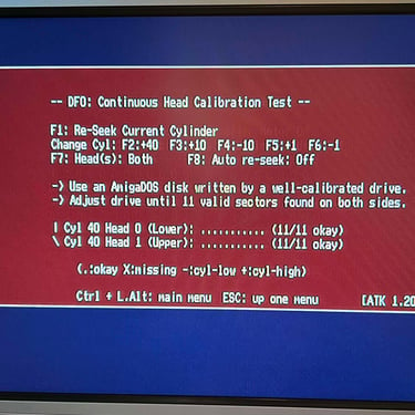
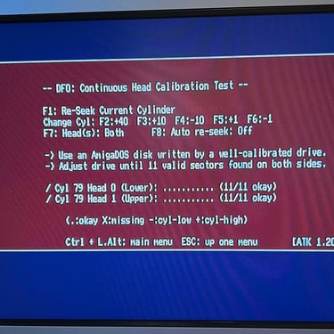
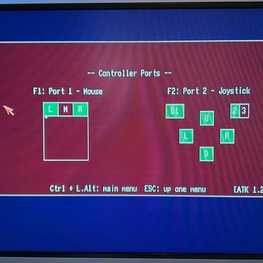
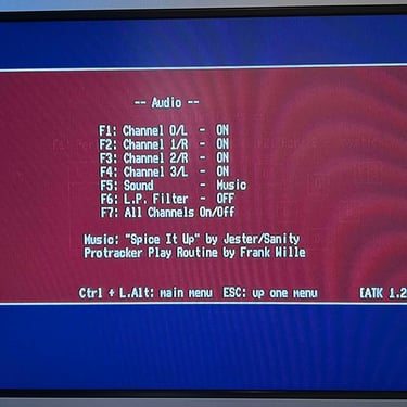
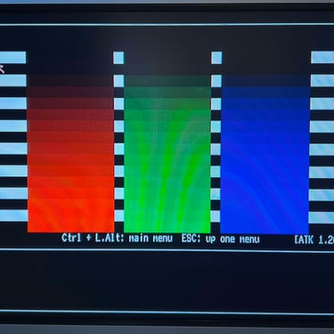
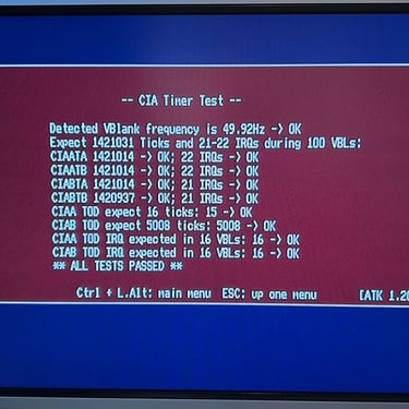
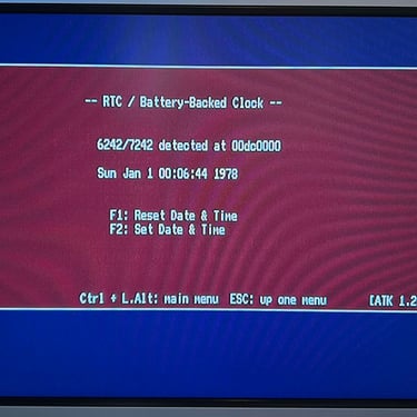
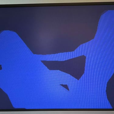
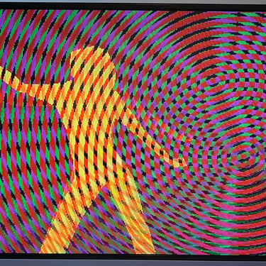
Now it is time for testing the whole machine. All parts such as keyboard, RAM expansion, keyboard and disk drive have been tested in isolation, but now I will try to test "everything". How? Well, I basically to this in two stages:
Formal testing with the Amiga Test Kit 1.20 (ATK). This will test most of the basic parts such as memory, floppy drive, video, audio, CIA, mouse, joystick and keyboard.
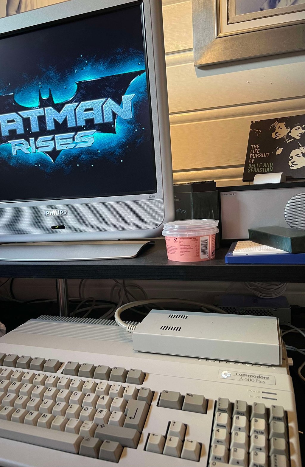
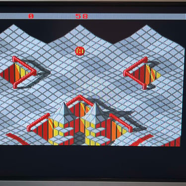
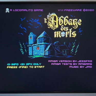
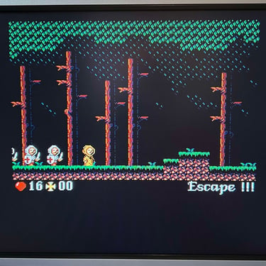
"Real usage" testing. I will basically use the machine playing games, watching and listening to demos and use the machine in regulator operation. This will detect flaws not easily detected with the ATK 1.20.
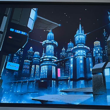
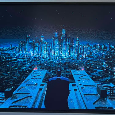
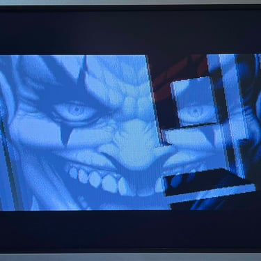
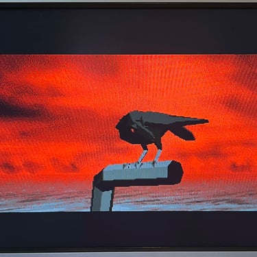
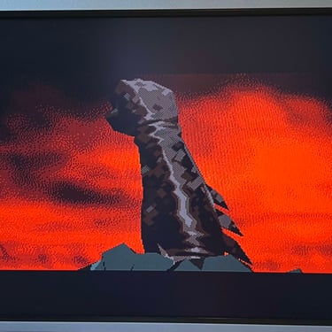
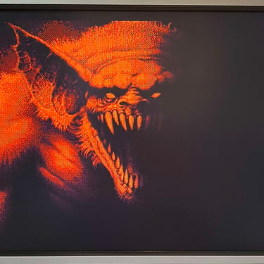
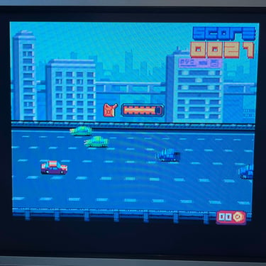
Below is a gallery from the final testing.








Final result
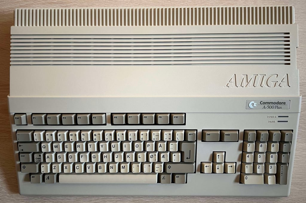
"A picture worth a thousand words"
Below is a collection of the final result from the refurbishment of this Amiga 500 Plus. Hope you like it! Click to enlarge!

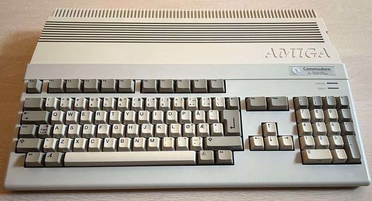

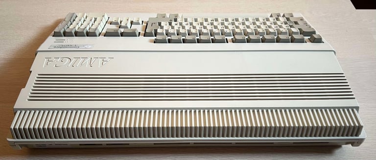

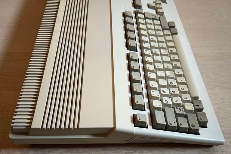

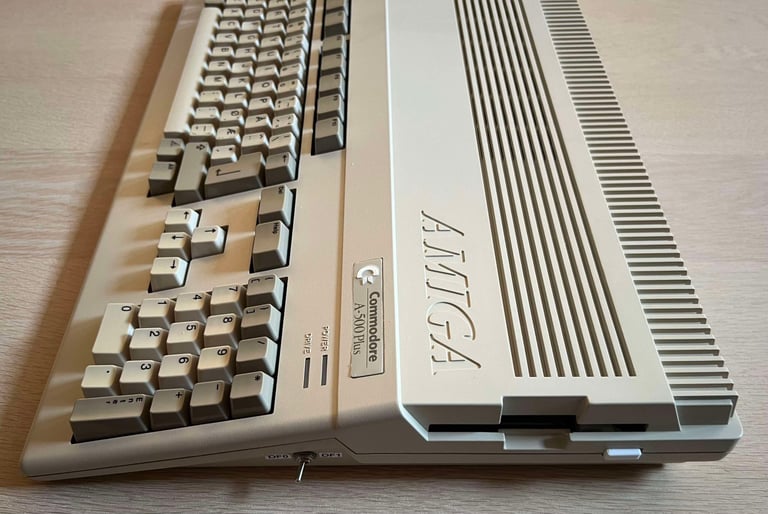


"Are you keeping up with the Commodore? 'Cause the Commodore is keepin up with you!"
Below are some pictures of the Amiga 500 Plus back at the customer´s home!
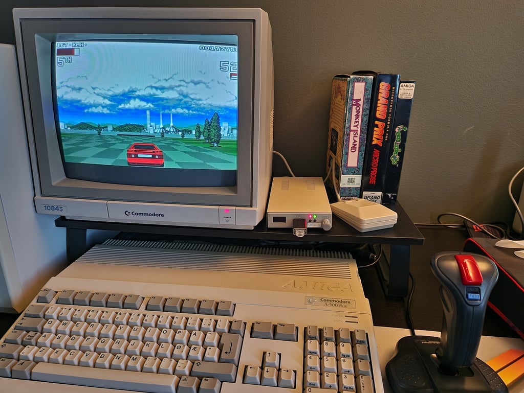

Banner picture credits: Ajne01
