
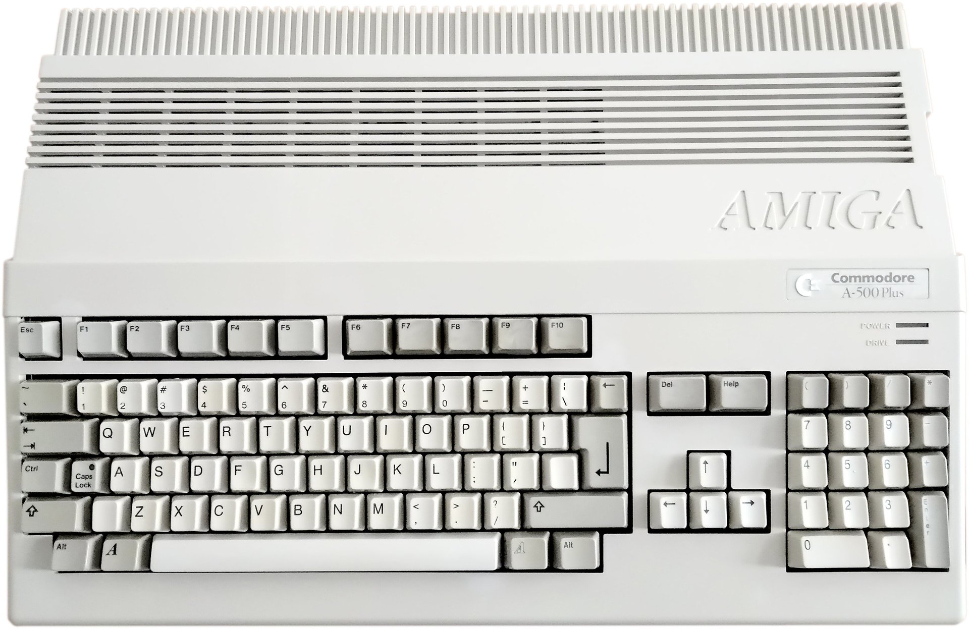
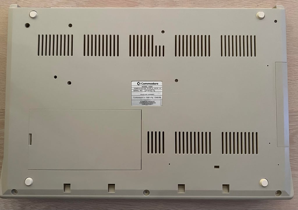
Amiga 500
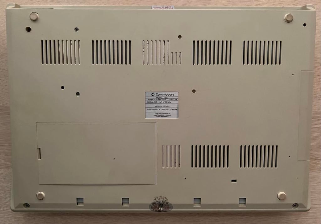
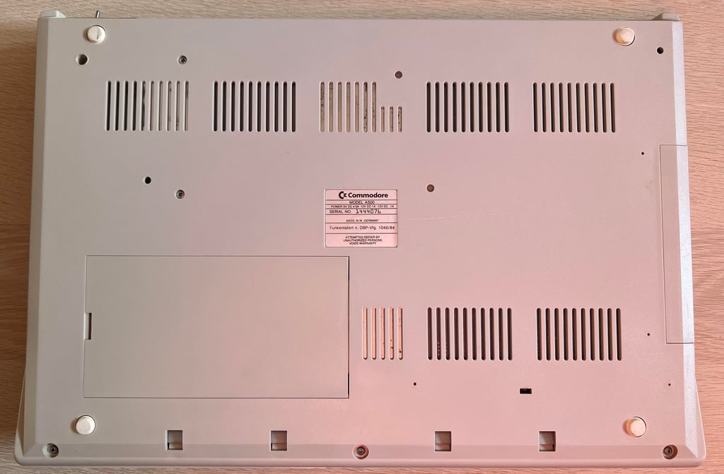
Ser. No. 144076
Assy 312510
Artwork 312513 REV 6A
Starting point
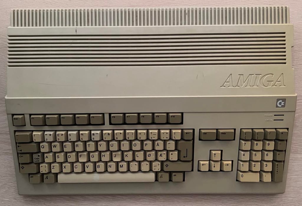
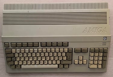
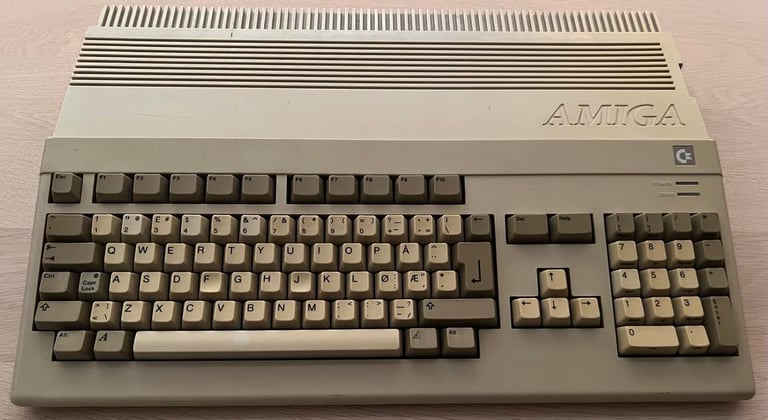
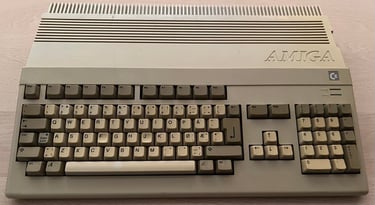
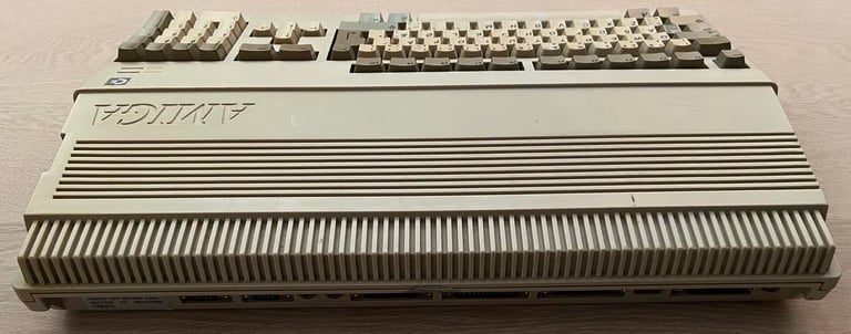
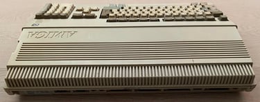
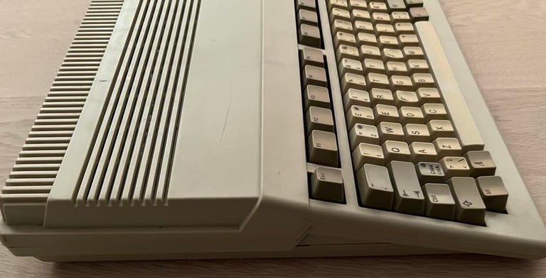
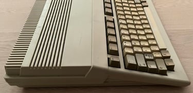
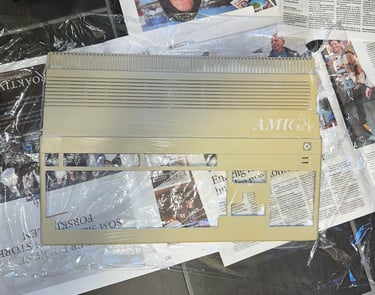
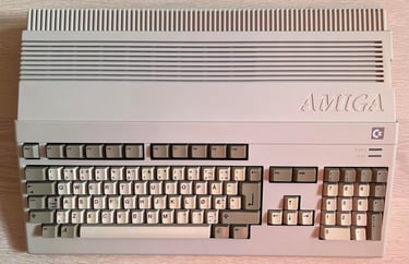
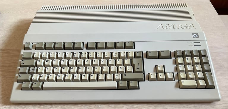
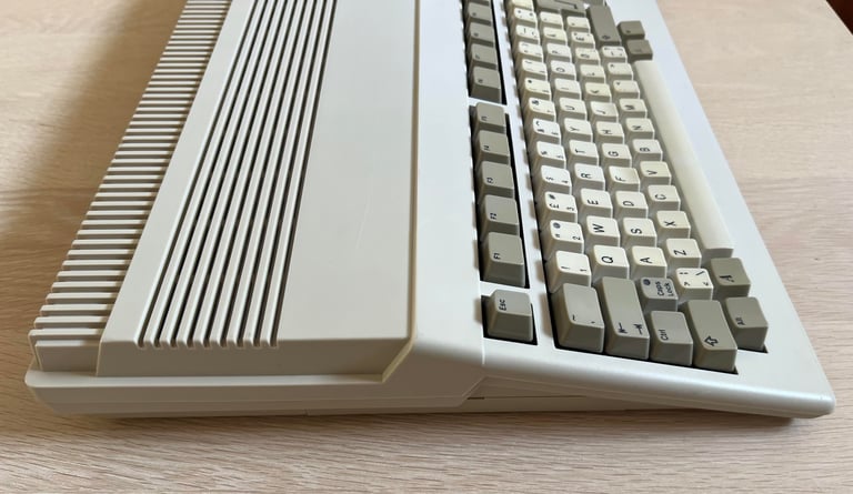
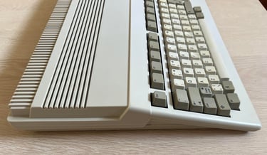
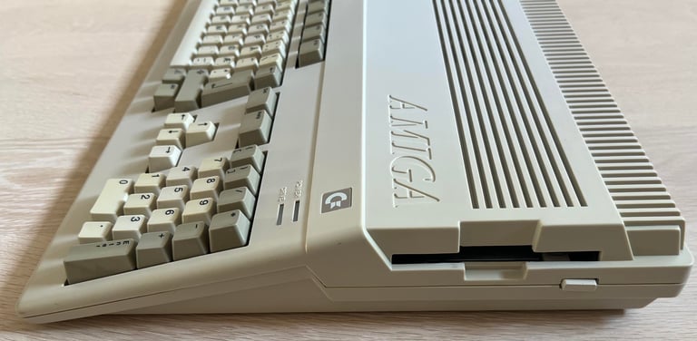
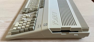
This Amiga 500 with 512 kB extra RAM should be a good starting point for a refurbishment. From the outside it´s a bit yellowed, and there are some small scratches - but I can not see any cracks or damage. This machine should be in a working state - so hopefully it will not be the toughest refurbishment job.

Refurbishment plan
To refurbish this Amiga 500 the plan is to do the following actions (several of them in parallell):
- Clean and restore the keyboard
- Clean and remove stains from the exterior top- and bottom cover/chasis
- Refurbish the main board (cleaning, checking, repairing, replacing capacitors etc.)
- Refurbish the internal disk drive (cleaning, checking and calibrating)
- Refurbish 512 kB RAM expansion card
- Install DF0/DF1 selector
- Installing and preparing external Gotek drive
- Verify operation by testing
Opens it up...
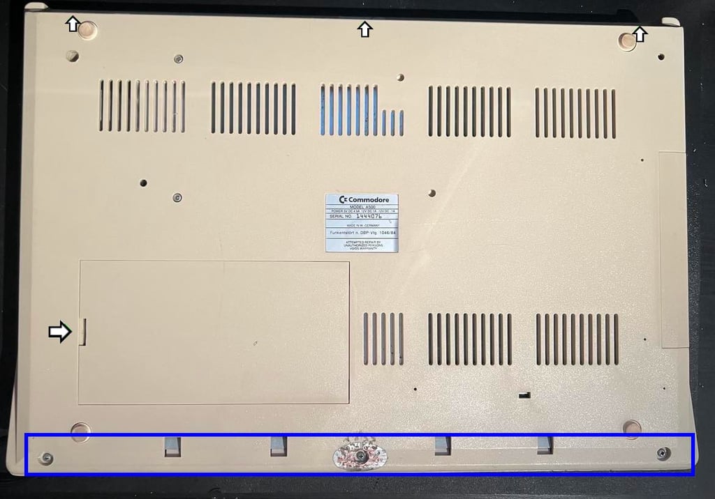
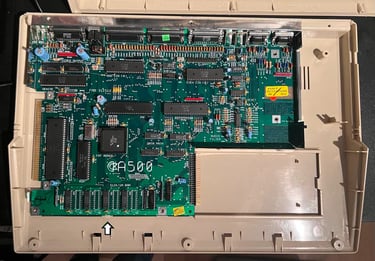
First the additional 512 kB RAM card is removed. It is just a matter of removing the trapdoor with a small flat screwdriver and then pull out the PCB (arrow). Note that the trapdoor cover can be brittle due to old age.
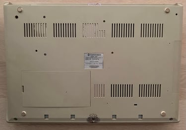
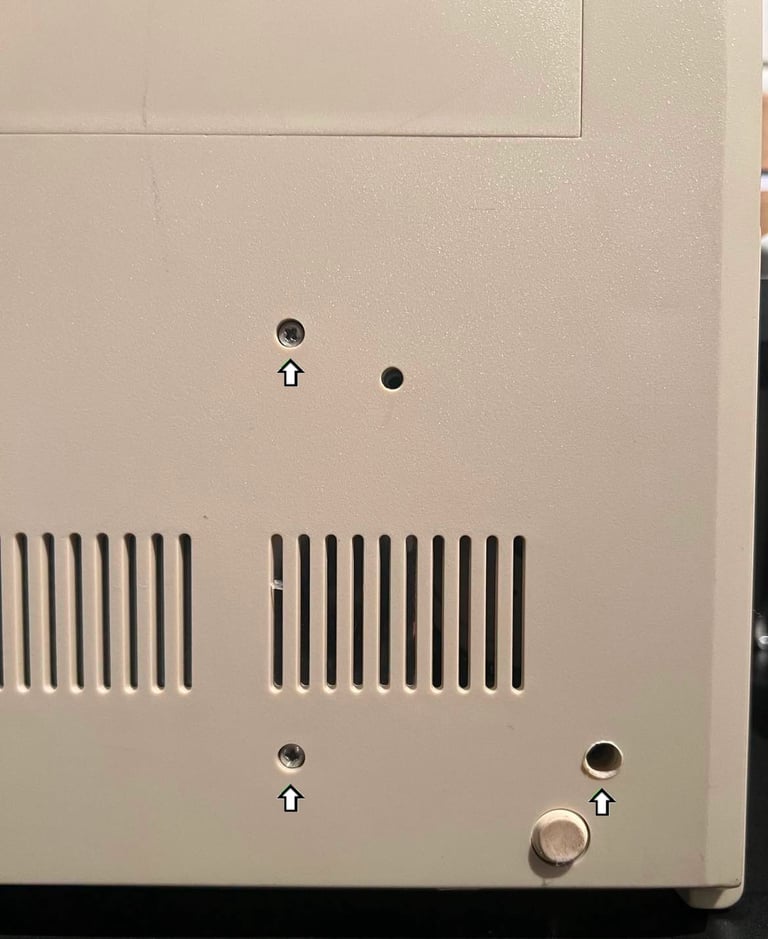
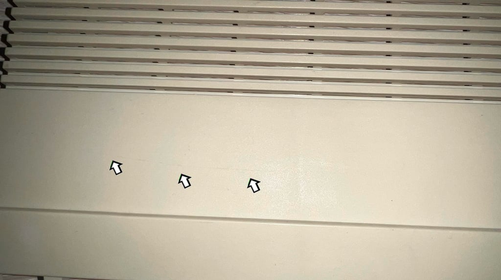
The A500 casing consists of a top- and bottom cover held together with six screws. For reasons unknown only the three at the front are in place (blue square)- the three at the rear are gone missing (arrows). So I need to replace these.
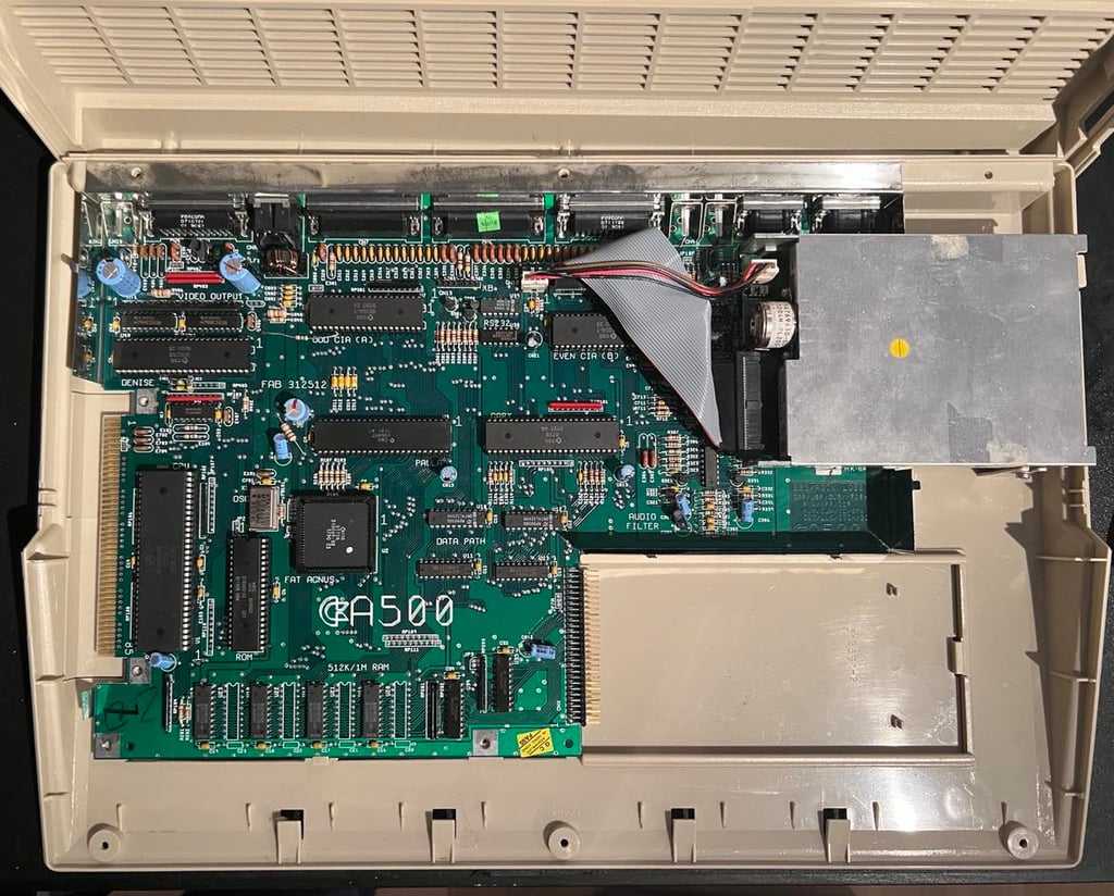
Top cover is removed and parts of the interior is exposed.
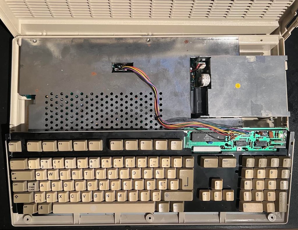

The keyboard connector is removed and the whole keyboard is lifted away from the bottom cover. As can be seen from the picture below the RF-shield is in good condition. There are some small areas of corrosion, but this is very common (and I have seen much (!) worse). But there is something else I now notice; many of the screws for the RF-shield/mainboard are missing. These needs to be replaced later. The RF-shield is easy to remove (since there are no screws...) after the four metal tabs are lifted to an upright position (see arrows).

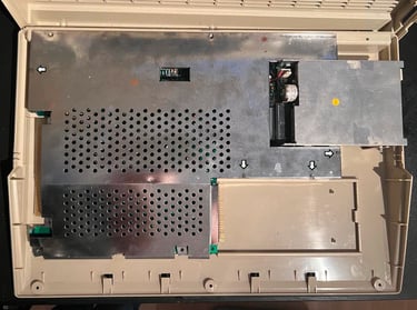
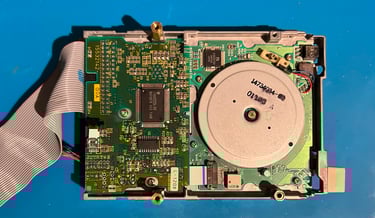
With the RF-shield out of the way the mainboard is now exposed. And it looks to be in very good condition. Very little dust and grease. Nice!

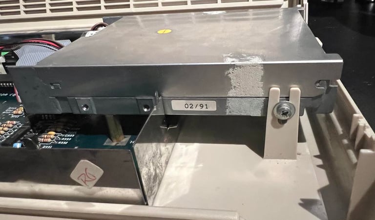
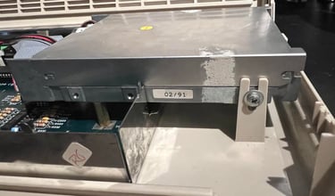
The floppy disk drive is removed by first removing the three screws at the bottom (see picture below). While doing this I discover that the screw used in the top right corner is wrong (!). Instead of using a fine machine screw a coarse wood screw is used. I will find a replacement for this later (perhaps one of the mainboard screws has been used here?)

Finally the screw on the side of the drive (in the plastic bracket) is removed, and the power- and data cable are removed from the mainboard.
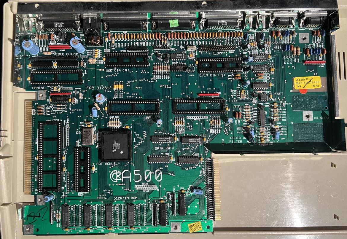
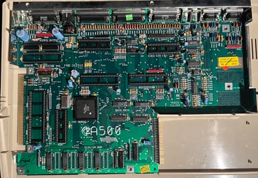
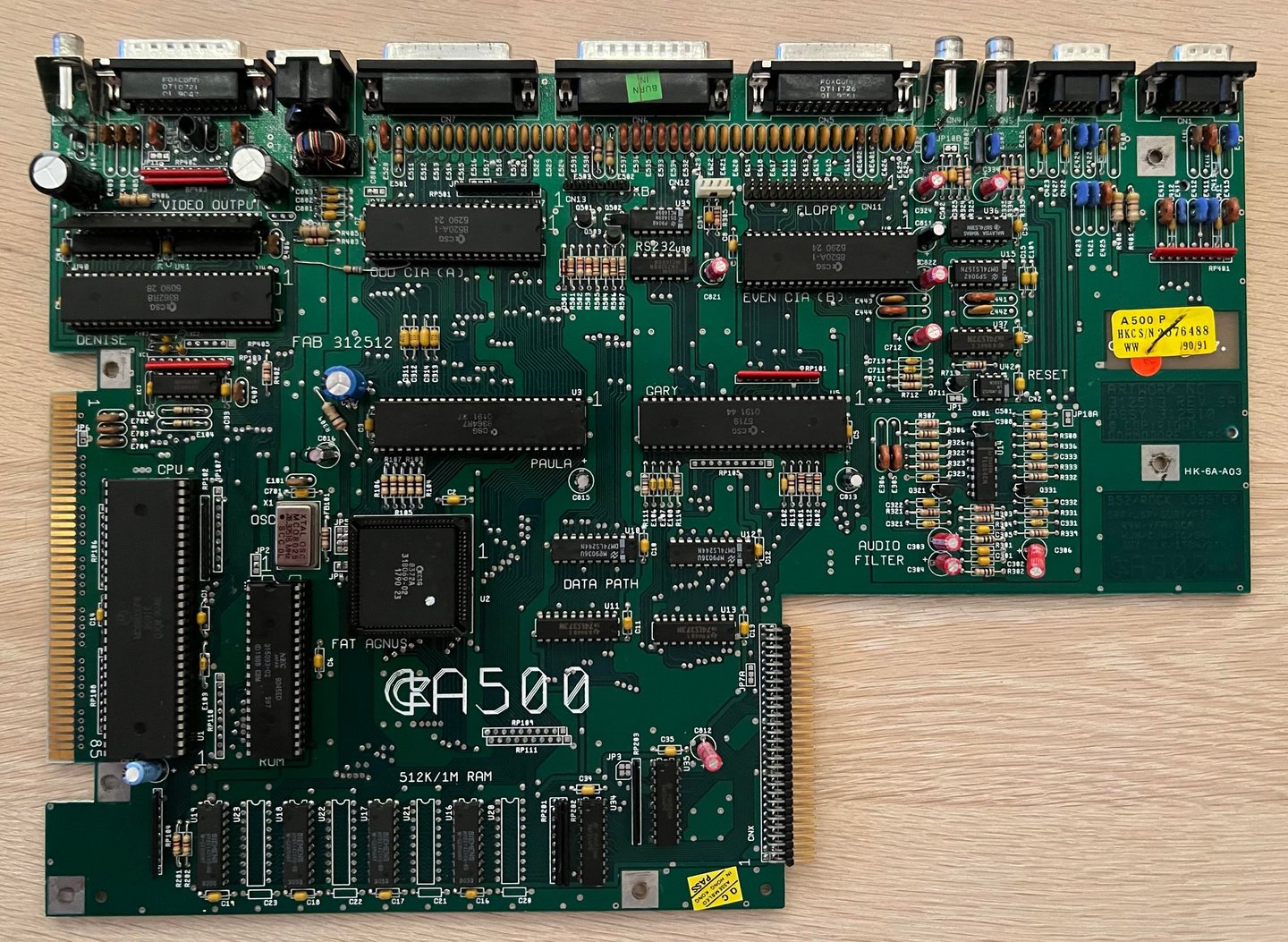
Now with the disk drive out of the way, the whole mainboard is exposed. It looks VERY good! This is the much wanted Rev 6A revision! The mainboard is carefully lifted out of the bottom cover while the small plastic clip is moved (see arrow - note that this can be brittle).

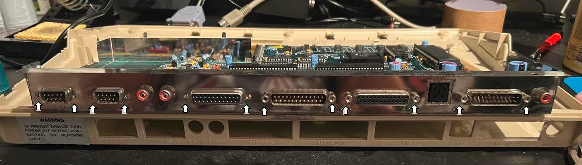
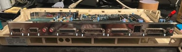
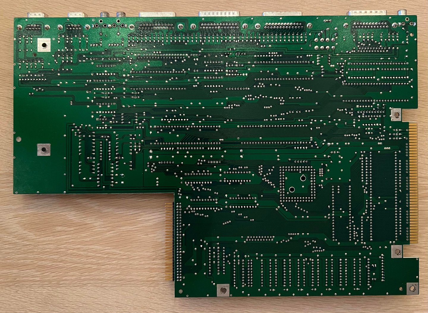
All the hex bolts are removed from the back of the metal cover shield (see arrows in picture below). With all these bolts removed the PCB can be lifted out.
Exterior casing
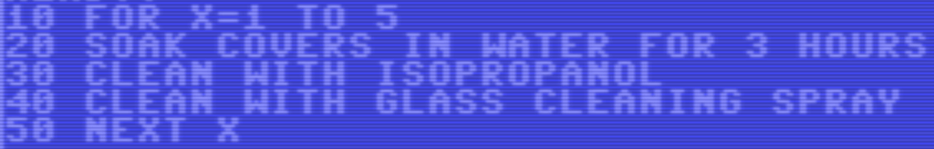
Cleaning the case
I was wrong. When I start working on this machine I thought that the outer covers were quite clean. They are not. Understand me correctly here, there covers have no cracks or severe damage, but there is a layer of dust and grease which is real hard to wash away.
Nevertheless, the grease and dust must be removed so the covers this is what I do:
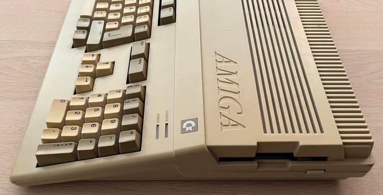
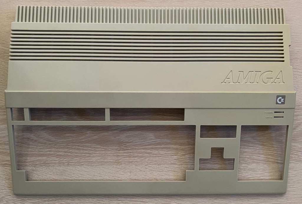
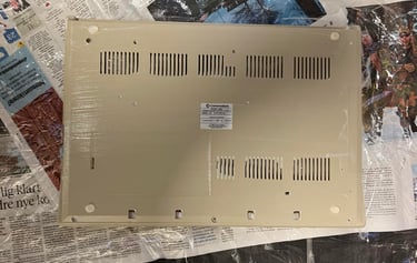
Finally the covers looks very nice and clean! I need to be very thorough with this cleaning. If they are not 100 % clean (e.g. some fat/grease residue) the retrobright process could result in areas with different colouring. Below are pictures of the top- and bottom covers after cleaning - but before retrobrighting. Note that there is a slightly more yellowed area on the right side of the top cover. This will be taken care of with retrobright.

There is a thin scratch on the top cover (see arrow below). It is not easy to see, but if you watch from a certain angle you will notice. Anyhow, I will not sand this away. Using fine sanding paper will probably remove the scratch, but you risk that the area will be slightly different (in colour and texture) so I conclude that it is better to leave it since this is really marginal. I know that many disagree with me, but I think its better to have an original A500 cover with a few scratches then purchasing a new modern cover.
Retrobrighting the case
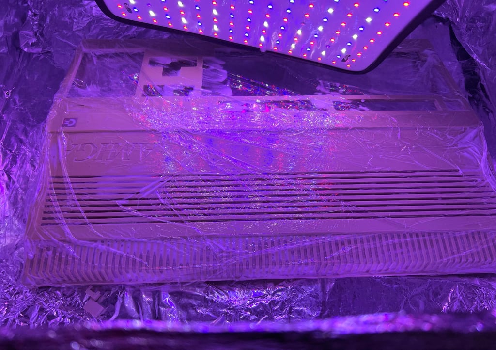
Retrobrighting is done in two stages; first the top cover and then the bottom cover. Why? Simply because the A500 cover is so big that I can´t fit both in my self made UV-box. The cover is covered with 12% hydroperoxide cream and wrapped in cling film before placed in the UV box for about 12 hours. Note that the hydroperoxide cream is replenished about every hours. See pictures below.


Mainboard
Visual inspection
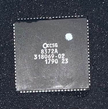
This is a Assy 312510/Artwork 312513/Rev 6A mainboard. The REV6A mainboard is also known as a "ECS" mainboard which is short for "Enhanced Chip Set" offering up to 1 MB of chip RAM (compared to "Original Chip Set (OCS) which only allow for 512 kB of chip RAM).
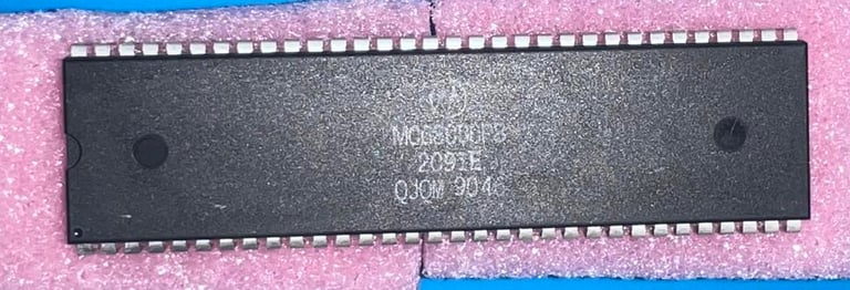
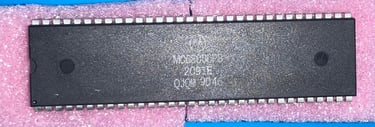
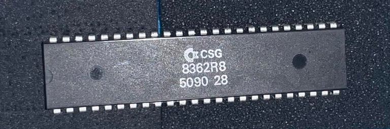
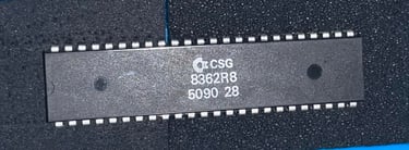
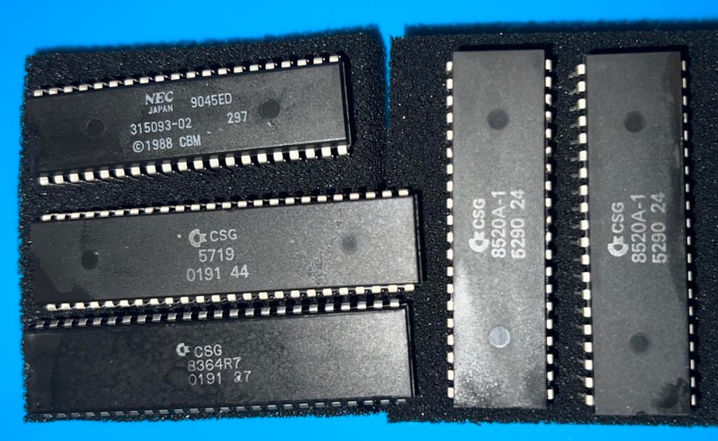
In the table below all the major custom IC found on the mainboard is listed.


Cleaning the chips and sockets
A quite common fault on A500 is that custom chips loose connectivity due to oxidized sockets. Therefore all the custom chips are removed from their sockets. And all chips are cleaned individually with glass fibre pen and isopropanol. Also, all the sockets are cleaned thoroughly with isopropanol and a tooth brush.
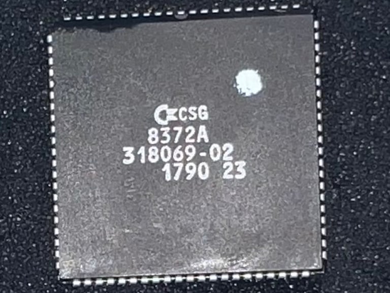
NOTE: Never attempt to remove the Fat Agnus 8372A chip without a PLCC extractor. If you use a screwdriver to pry it loose you risk (with a very high probability) to break either the PLCC socket or the chip. If you don´t have a PLCC extractor you can push the Fat Agnus out of its socket from below by pushing a stump shaft through the two small holes at the back of the PLCC. I don´t recommend this though...
Below are some pictures from the cleaning process.
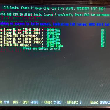
Initial testing - Boot up screen and Amiga Test Kit
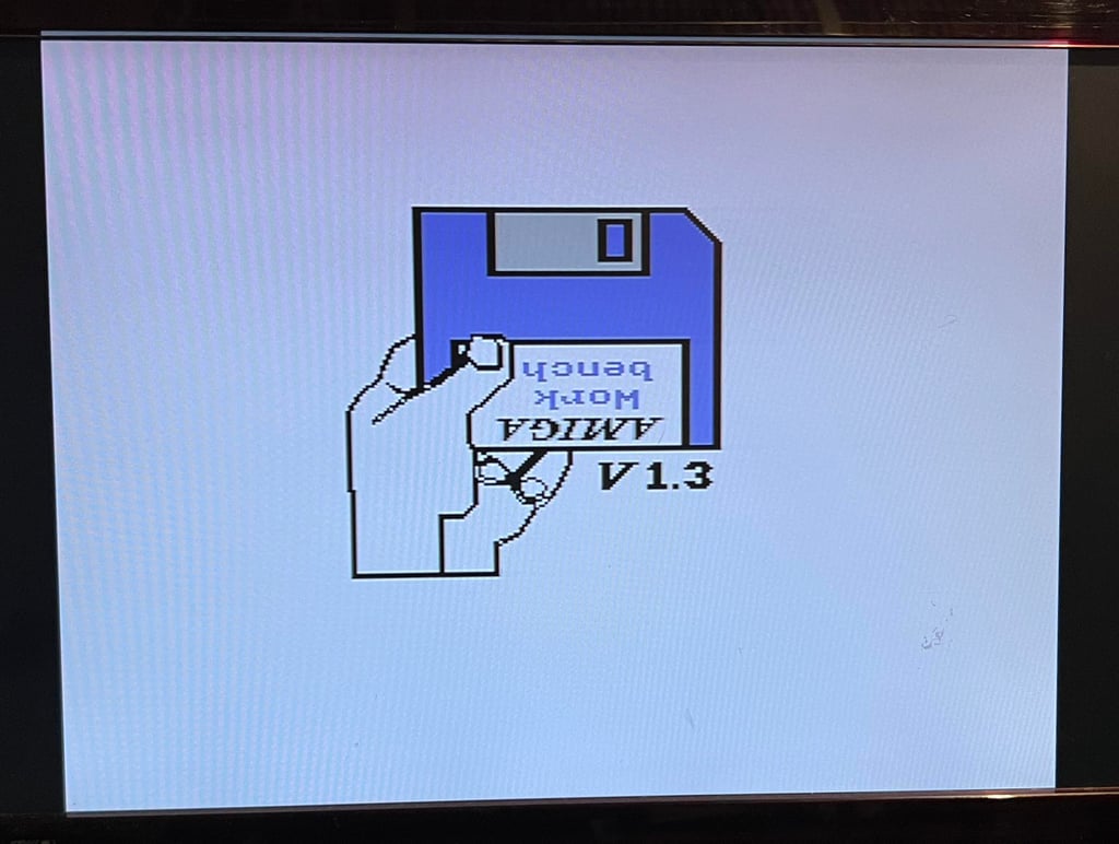
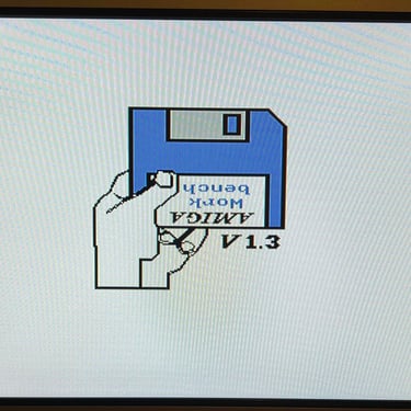
Does the machine works? The un-refurbished keyboard and disk drive are connected to the mainboard. Initial testing is very promising. First the initial bootup screen appears showing that this is a an A500 with Kickstart 1.3 ROM installed.
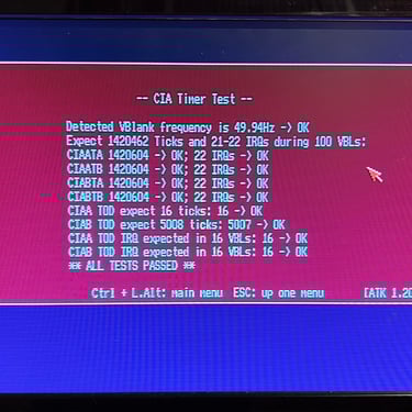
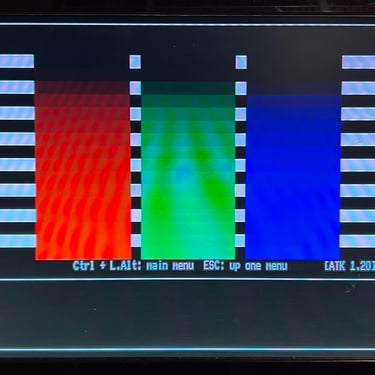
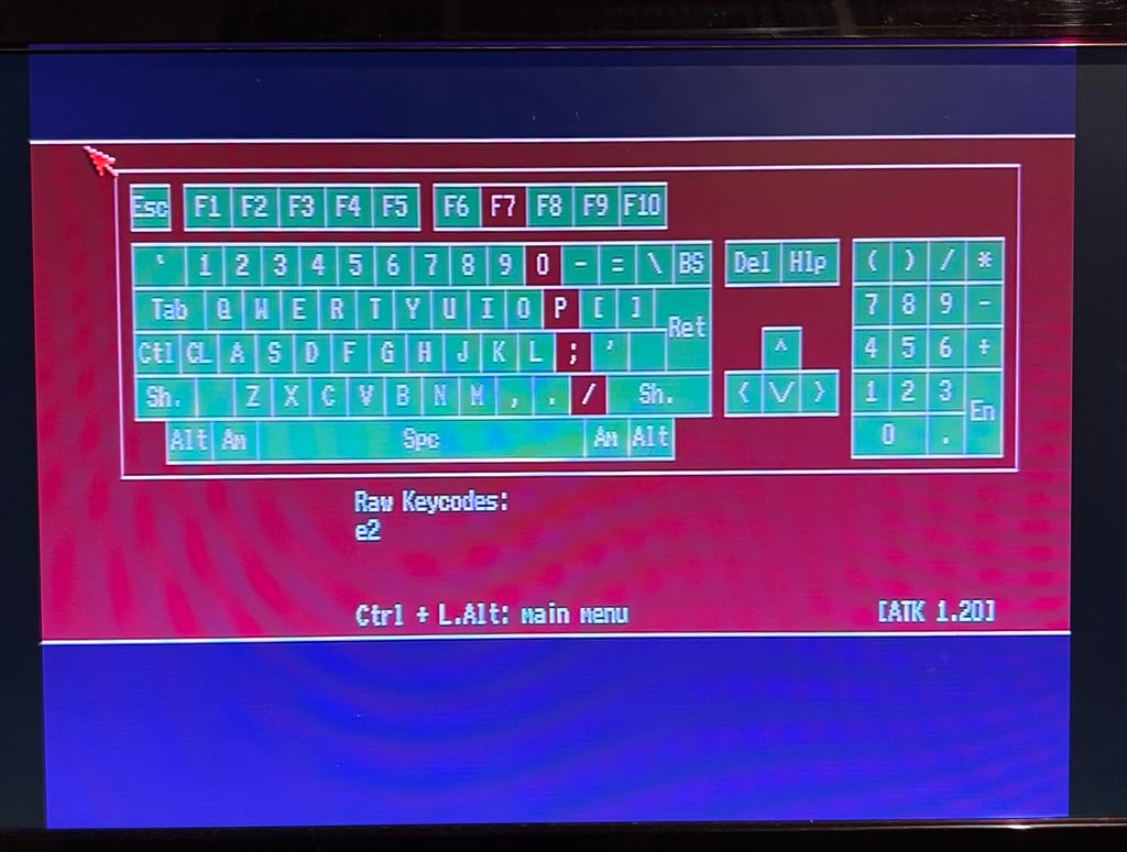
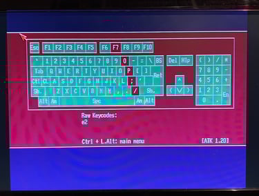
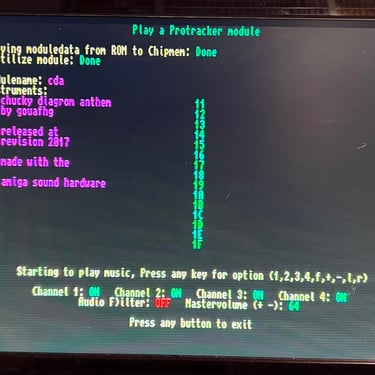
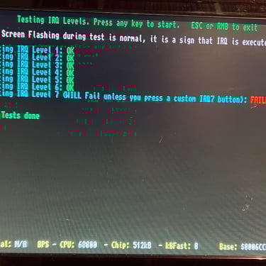
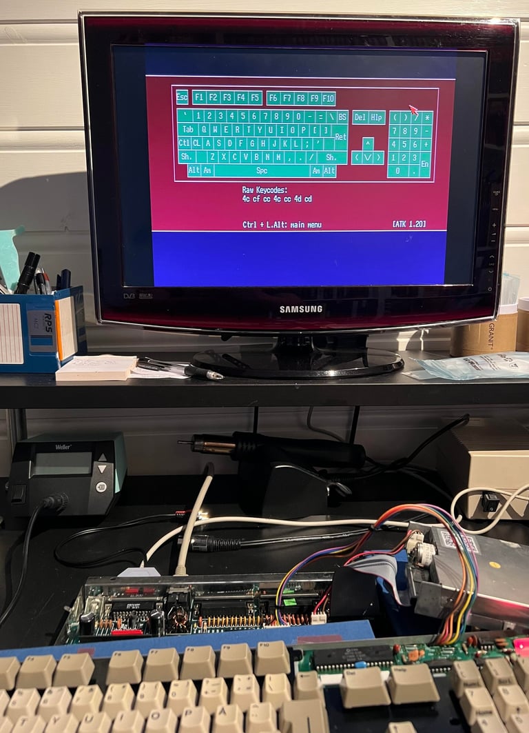
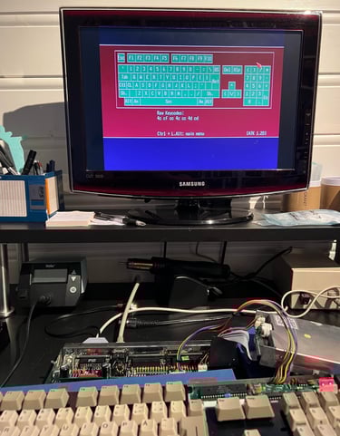
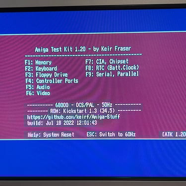
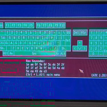
The Amiga Test Kit floppy is inserted in the drive - and the disk drive boots the disk without any issues. All the main tests for RAM, video, audio, IRQ and CIA pass without any issues. But the keyboard test fails; F7, 0, P, ; and / does not work. Most probably a bad trace on the keyboard membrane. See picture gallery below.
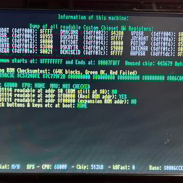
Initial testing - DiagROM
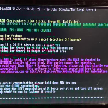
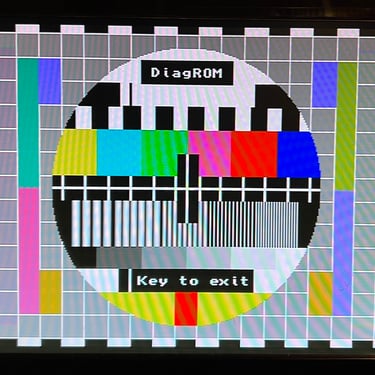
A very good tool for testing is the DiagROM chip. This chip replaces the Kickstart ROM and gives detailed test information when installed. With this chip installed all tests pass as far as I can see (the keyboard test is not done here). See pictures below.
Replacing the electrolytic capacitors
It is good practice to replace all the electrolytic capacitors on the mainboard. After 30+ years these capacitors are likely to dry out and loose their ESR value, and since these capacitors are often used as voltage filters you can risk that some components do not work as they should if the capacitors are bad.
Replacing the 17 capacitors is quite straightforward, but since this revision of the mainboard has substantial ground plane it does require some heat to do the desoldering. Now, to desolder the capacitors on the Amiga 500 I quite often use both the soldering iron and the desoldering gun. This is to make sure that I can apply sufficient heat - but ONLY for a short time in order to not damage traces/pads.

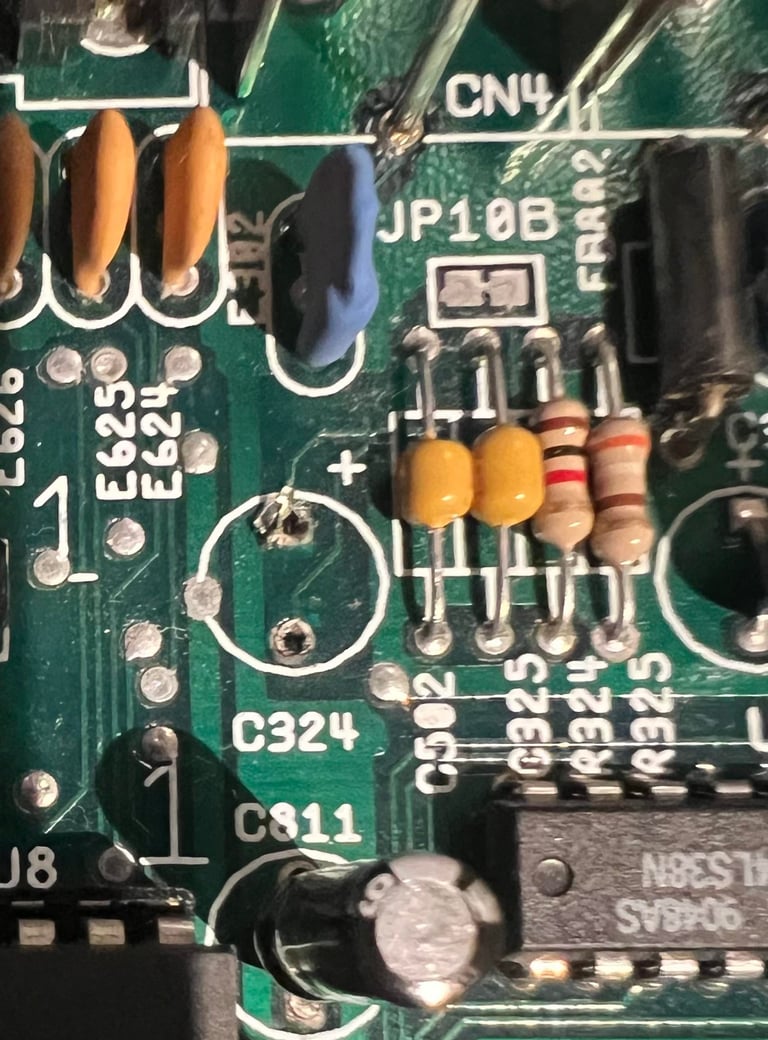
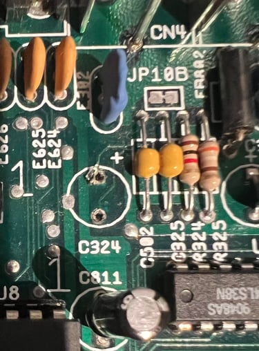
During the recap I accidentally lift a trace at the positive pin at C324 capacitor. This happens sometimes, but when checking connectivity I can not find any damage. And the trace is fixed in place after soldering. Even if there are no real damage I think it is important to document this.
Keyboard
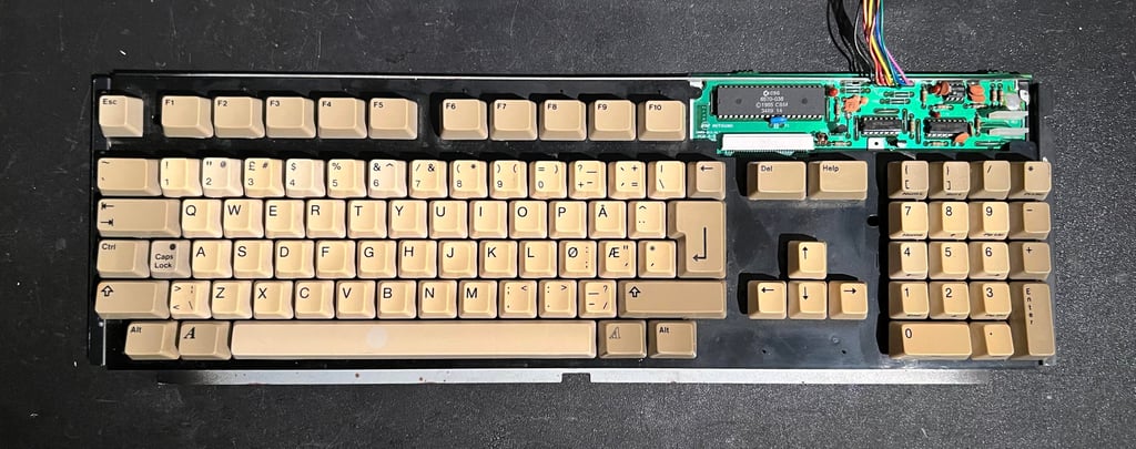
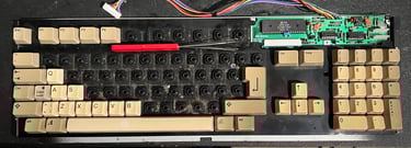
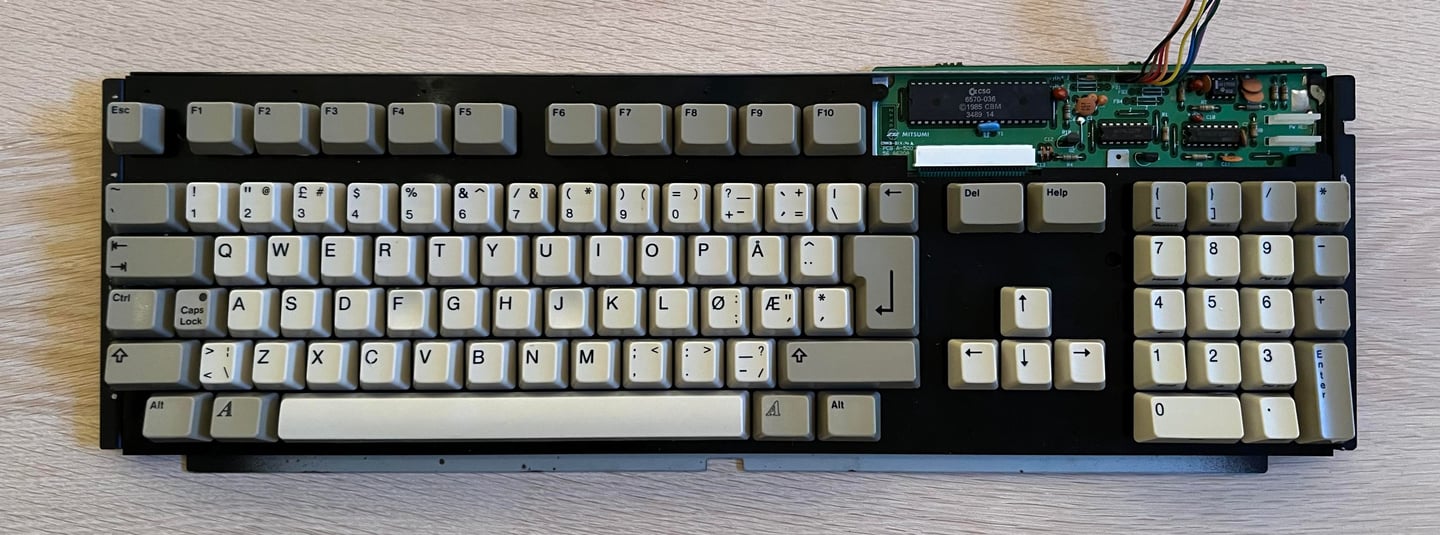
The keyboard seems to be in very good condition. As the initial testing shows there are issues with this (some of the keys do not work), but this is quite common on these keyboard. The original membrane in these keyboard are notorious for failing so it could be that causing some of the keys not working. Also the keys are quite yellowed, but I think I can get these back to it´s original colour. Notice that this is the Norwegian keyboard layout.

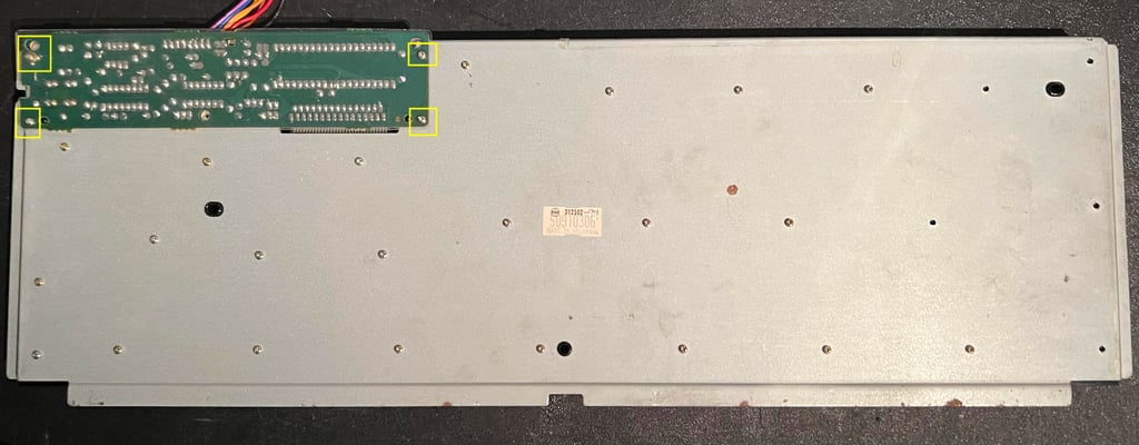
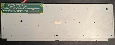
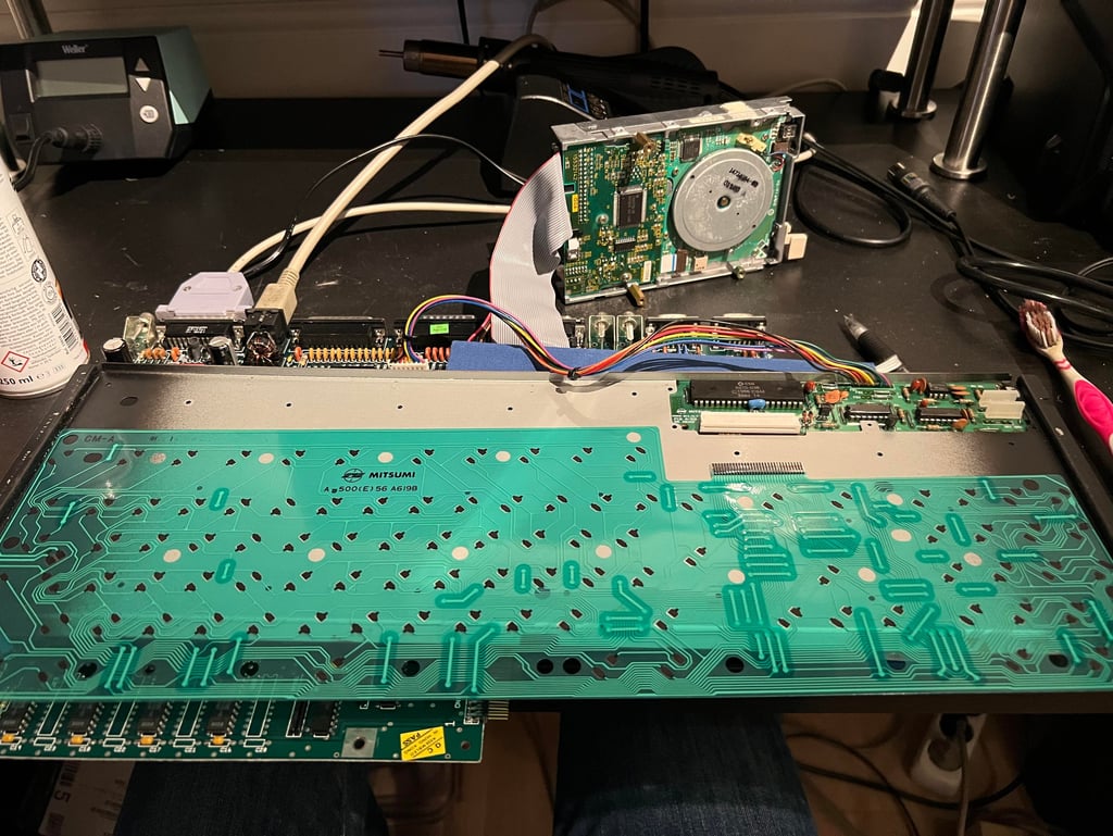
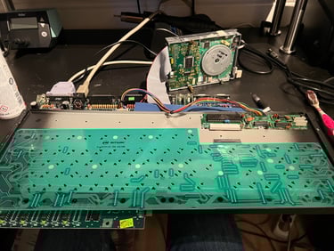
To check the membrane and the keyboard PCB the screws on the backside are removed. Note that there are four screws at the top left side which holds the PCB to the metal chassis - and that one of these screws (top left) is actually beneath the plastic cover.
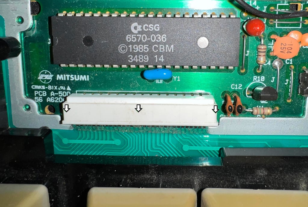
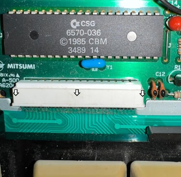
The membrane is removed from the connector by first pushing the top of the plastic connector casing downwards (see arrows). Then the membrane is carefully wiggled out of the connector.
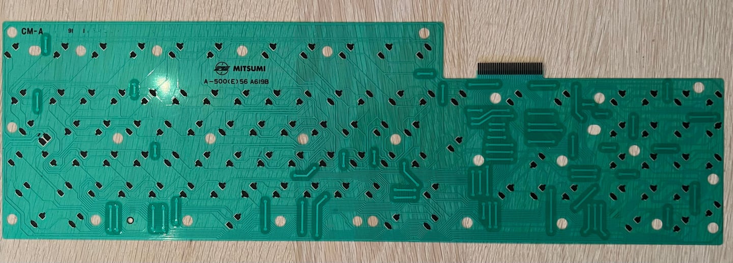
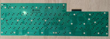
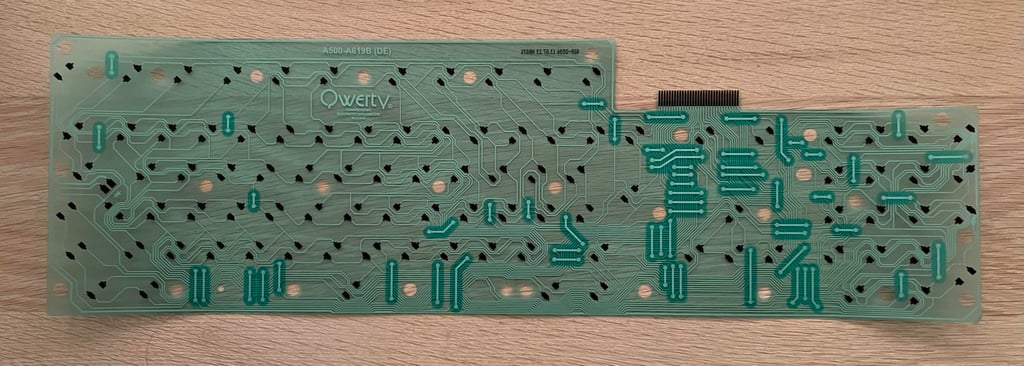
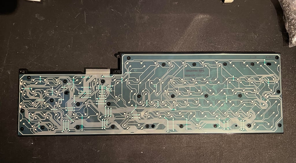
When the membrane is out of the chassis it is carefully cleaned with isopropanol and some paper towel. Be very careful not to damage any of the pads. Below is a picture of the cleaned membrane. As can be seen this is a standard MITSUMI membrane (which unfortunately fails quite often).
Checking the membrane
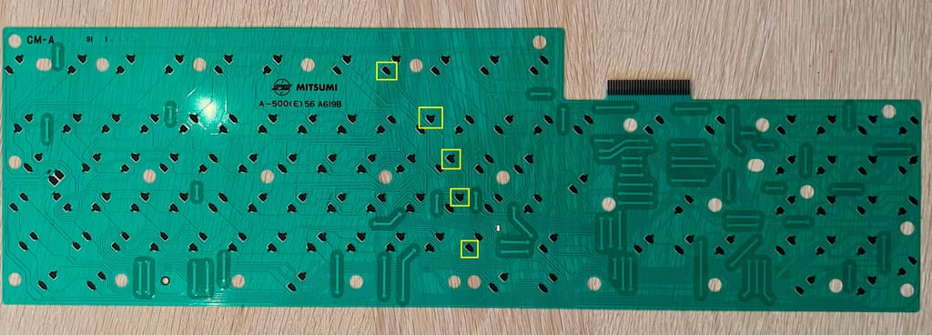
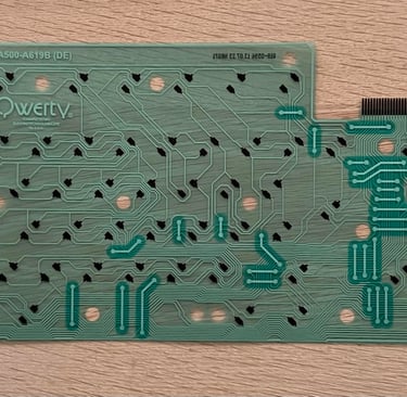
After cleaning the membrane it is tested. And it turns out that there is a bad trace. Below is a picture from the testing process.
With the multimeter I measure the traces and I see that the broken trace is somewhere between the arrow (see picture below) and the membrane connector. It is not so easy to detect the exact place of the broken trace. The trace is fine from all the yellow squares until somewhere around the arrow.
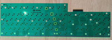
It is very common that one (or several) traces are broken on these old membranes. I think the reason is that moist enters the membrane, and since the coating over the copper traces is so thin that traces start corroding. Nevertheless, there are modern substitutes available. So a new replacement membrane is ordered from amigastor.eu. Below is a picture of the new membrane.
Cleaning the keys
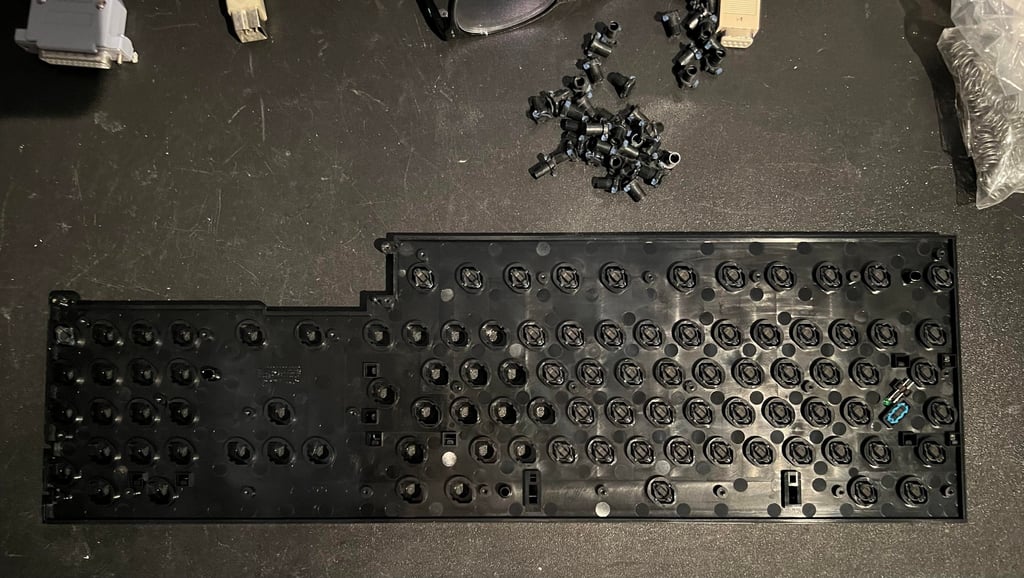
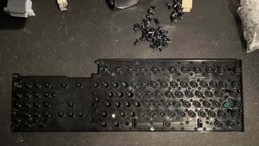
Each keycap is removed from the keyboard with a puller. It is highly recommended to use a keycap puller to do this so that you don´t risk damaging the keys or the plungers. Note that beneath the spacebar there are two small springs which are different from the other springs. So it is good practice to keep these two separate. Also note that some of the larger keys (Enter, shift, spacebar etc.) have a small metal U-shaped support bracket. Below is a picture from the process. There are quite some dust and grease on the keyboard, but that is expected after 30 years.

All keycaps are placed in a bowl of mild soap water and some glass cleaning spray for about 12 hours. This will remove most of the grease and prepare them for retrobright.
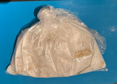
Retrobrighing the keycaps
The keycaps are placed in a double bag of hydroperoxide cream (12 %) for about three to four days. To make sure that the keys do not dry up inside the bag it is frequently massaged and turned. If the keycaps dry up too long you risk a marble effect on the keys. Fingers crossed!

Assembly and testing
The keyboard is assembled again; all plungers, brackets, spring and keycaps are put back on the keyboard. I am quite happy with the result - I think it looks very nice thinking that this keyboard is way over 30 years old.


And now to testing... does it work? Yes! All keys are functioning as they should.
Disk drive
The internal disk drive in this Amiga 500 is a TEAC FD-235F with serial number 8345419. From the outside it looks very nice - not any sign of corrosion or damage.
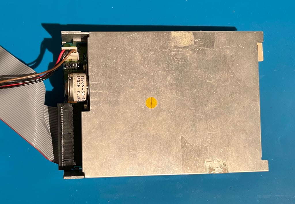


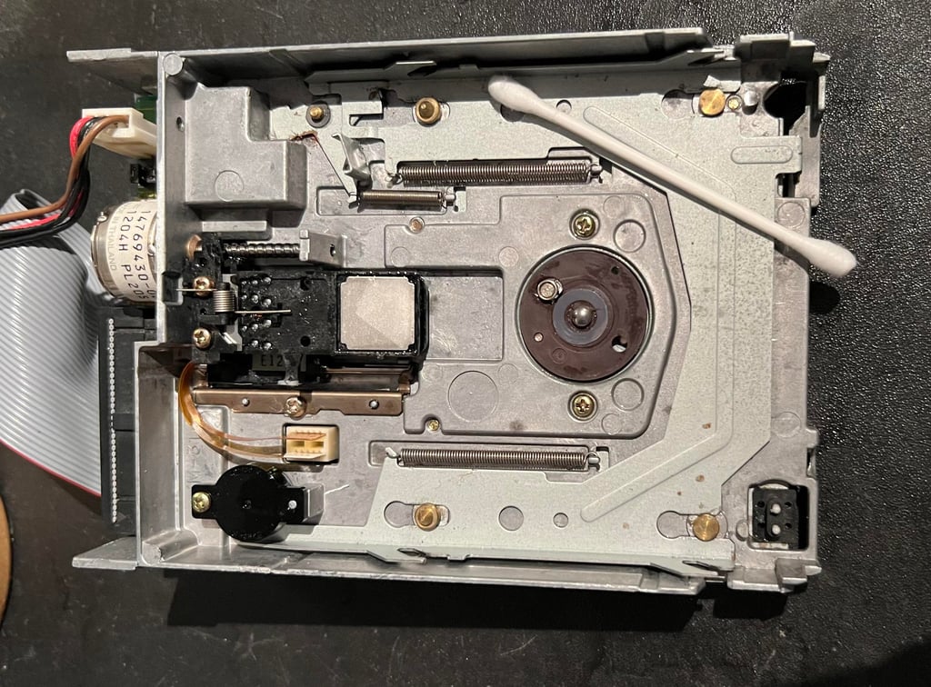
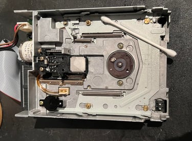
Opens it up...
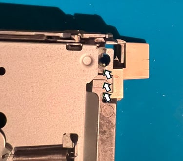
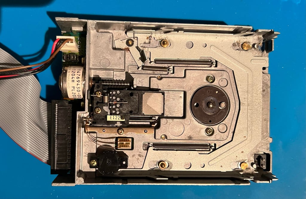
To open the disk drive is very easy. There are two metal tabs on each side of the drive which holds the top metal cover. With a small flat screwdriver the cover is lifted away from the tabs. With the top cover away, the interior is shown. And it looks very nice - and surprisingly clean.
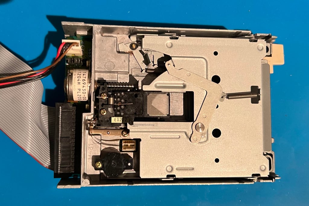
The small plastic eject button is removed by gently lifting upwards and way. There are some small grooves in the eject button from usage. I will see after retrobright if it needs to be sanded.

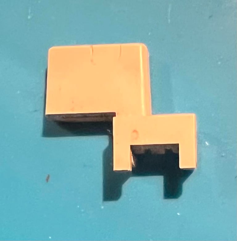

Finally the inner metal cover is removed. I do this by pushing the (removed) eject button gently and at the same time lift the back of the inner cover upwards. There are some grease here and there, but not much really.

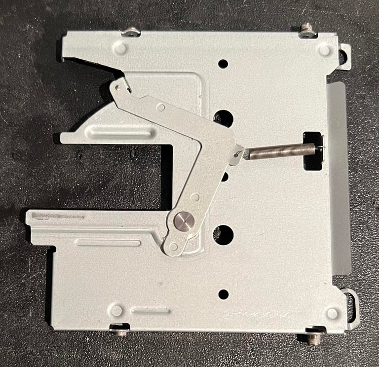
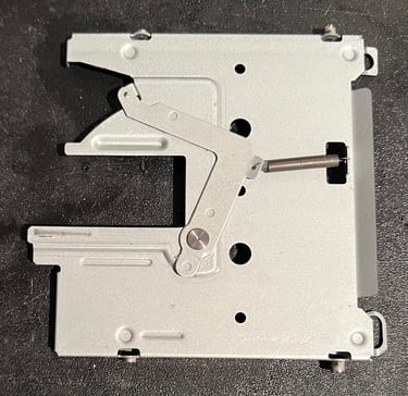
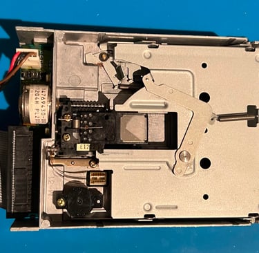
Cleaning and lubricating
All of the interior is cleaned with isopropanol on a Q-tip. As previously mentioned there are not much dust and grease, but it is good to clean it anyway. The R/W heads are also cleaned thoroughly. WARNING: note that the top R/W head is very fragile! So when cleaning this head make sure that you do not rush this - and make sure that the Q-tip does not rip the head out of position! Below are some pictures after the cleaning.
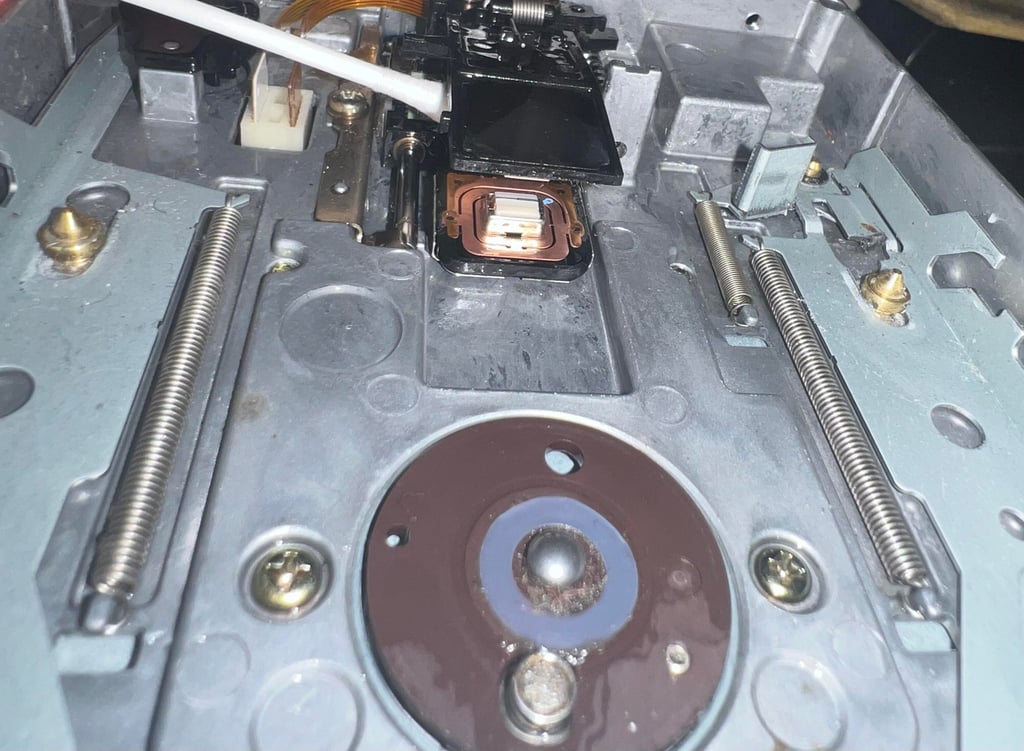
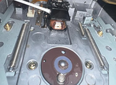
The spindle is first cleaned thoroughly with isopropanol. Then it is lubricated with sewing machine oil. I find this kind of oil the best lubricator - it is thin, liquid and does not dry up fast. After lubricating the spindle is "massaged" by steering the R/W heads up and down the rails while the drive is connected to the machine. See video below.

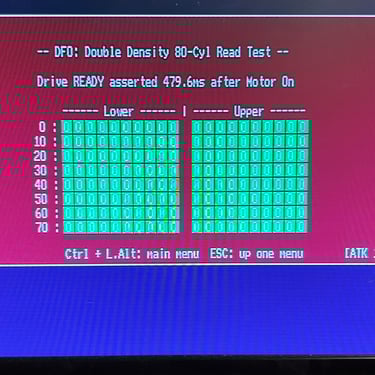
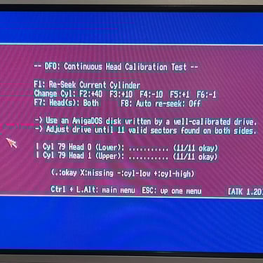
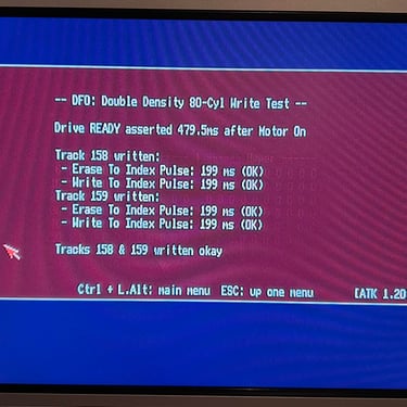
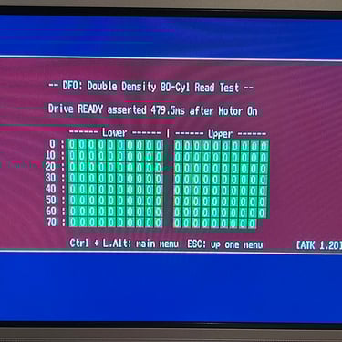
Initial testing
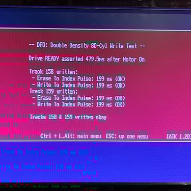
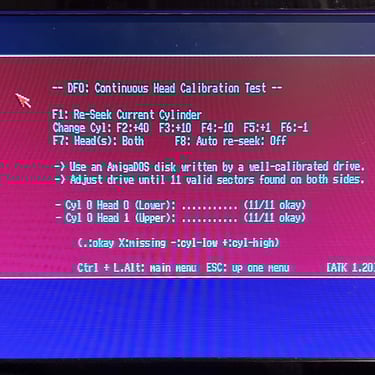
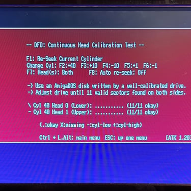
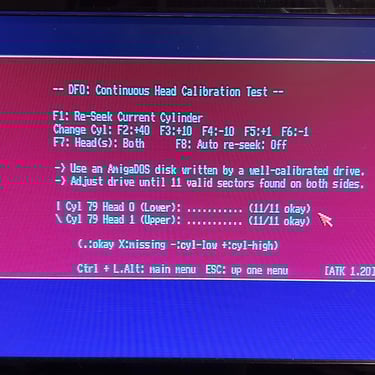
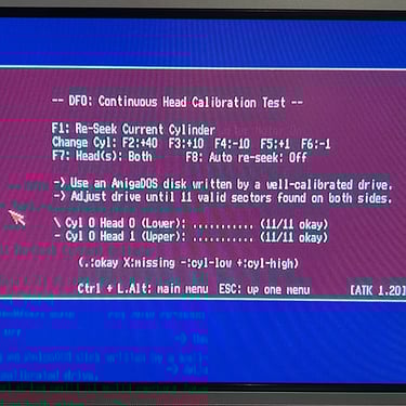
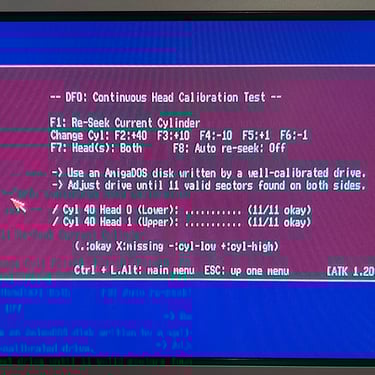
An initial test of the disk drive is done by using the Amiga Test Kit software. All tests pass without any issues - so this is very promising.
512 kB RAM expansion
Back in the days when the Amiga 500 were released 512 kB of memory was VERY much. And the idea of adding 512 kB RAM in addition... whoo! We are now talking a whole whoppin´ 1 MEGABYTE of memory!
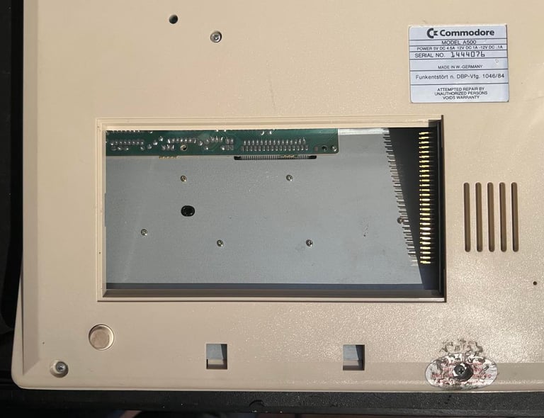
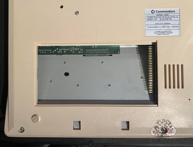
Underneath the Amiga 500 there is an expansion tray with the sole purpose (as far as I know) to add 512 kB of RAM.
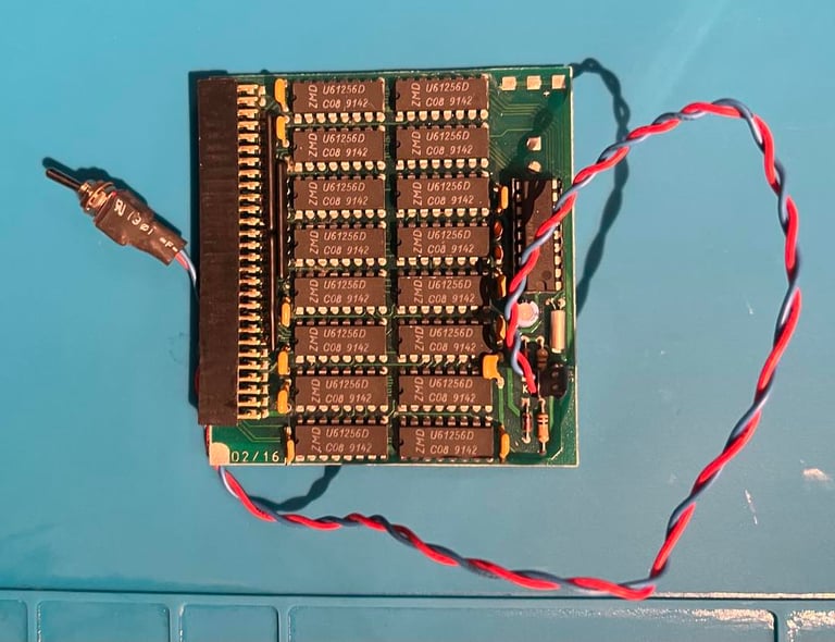
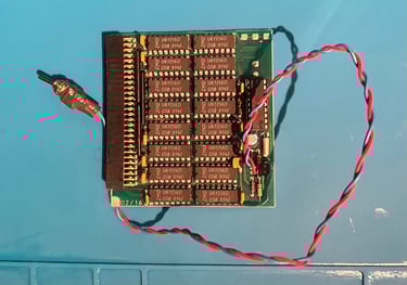
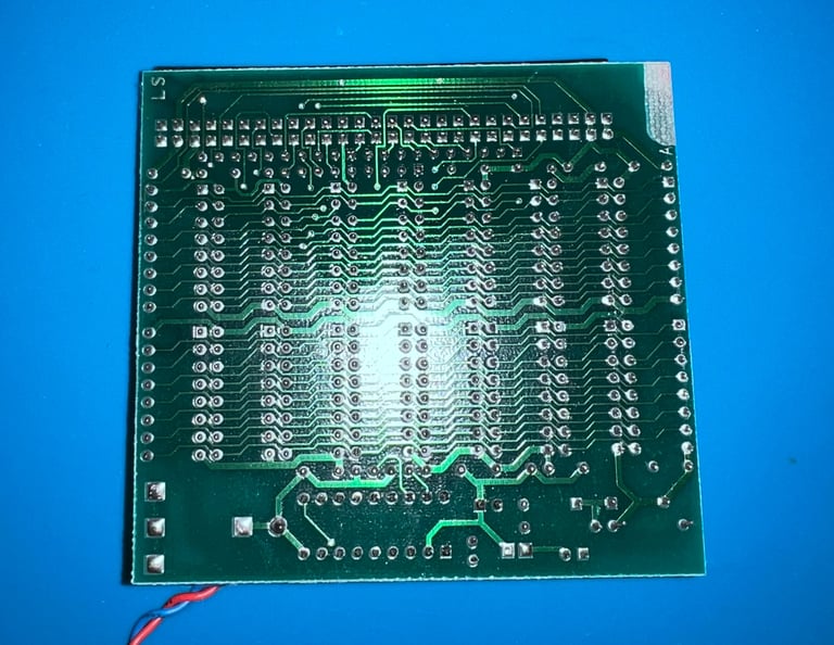
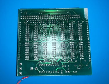
This memory expansion looks very good already, but it is cleaned with isopropanol (both side of the PCB). Luckily, there are no battery that could leakage and corrosion. See pictures below.
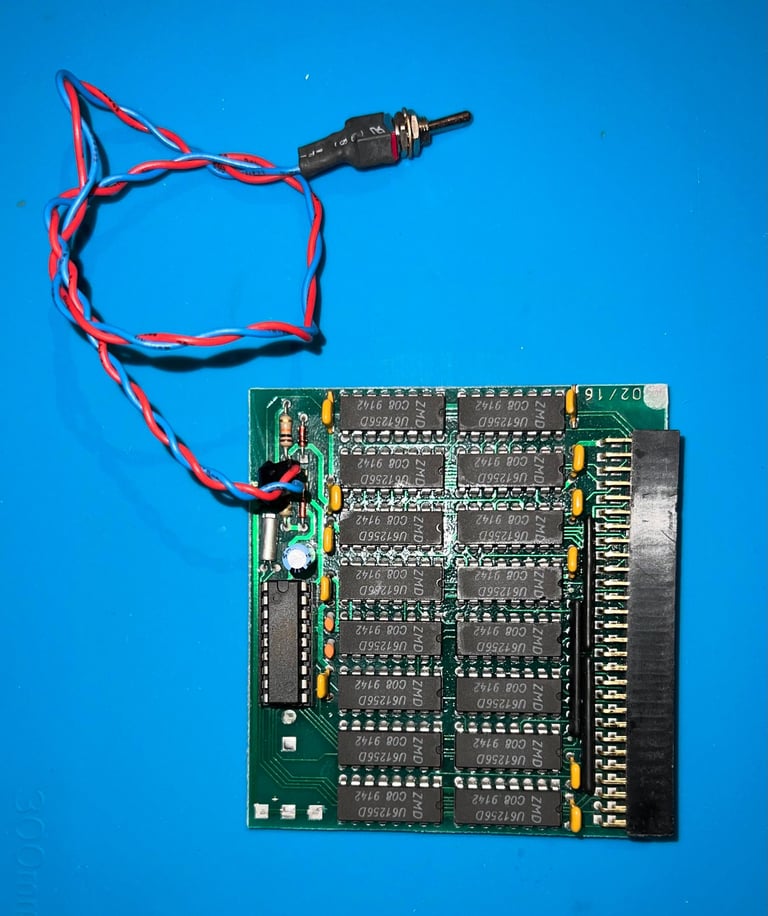

The board is made up of 16 ZMD 61256D RAM chips manufactured in week 42 of 1991 which is about the same time as the Amiga 500 mainboard. Each chip store 256 kiloBITs (16 x 256 kiloBIT = 512 kBYTE). Also note that there is a switch for enabling/disabling the RAM expansion. This is rarely used, but there might be occasion where you want to turn the card off (try playing Operation Stealth with 1 MB RAM - after 10 minutes of playing you are quite tired of hearing all text transformed to Amiga "SAY" commands...).
There is a 4.7 uF 63V (!?) capacitor on the board. It looks to be fine - so I choose to leave it for now. I have 4.7 uF spares with voltages up to 35 V which probably would work fine, but I think I can leave it. And replace it if I find any issue with it.
Testing the expansion RAM module
To test the 512 kB RAM expansion the card is installed on the Amiga 500 mainboard. Then the internal floppy drive is connected and the Amiga Test Kit is loaded.
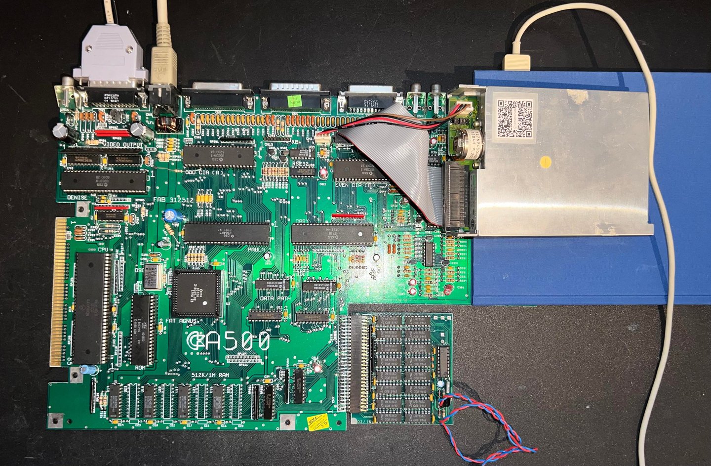

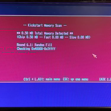
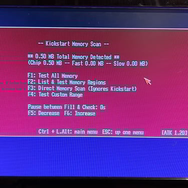
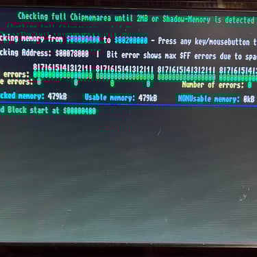
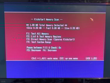
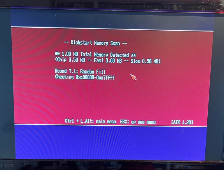
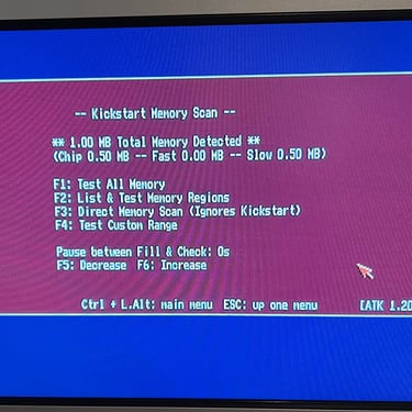
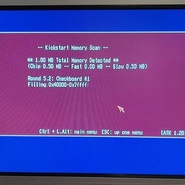
The RAM expansion is detected without any problems. As seen from the picture below the Amiga 500 detects the full 1 MB of RAM as a sum of 0.5 MB of CHIP RAM and 0.5 MB of SLOW RAM. Note that SLOW RAM is what the Amiga 500 should see here so this is correct. The reason why it is called SLOW RAM is that this RAM is accessed with the same speed as CHIP RAM. It can not be used as CHIP RAM, but it can not access it as fast as FAST RAM.


DF0/DF1 floppy drive boot selector
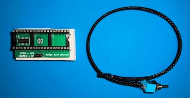
This Amiga 500 will use an external Gotek drive in addition to have an original Amiga floppy drive. To be able to use the external Gotek drive as the "primary floppy drive" a DF0/DF1 switch is installed. With this switch the user can select which floppy drive to boot from; either the internal floppy or the external Gotek.
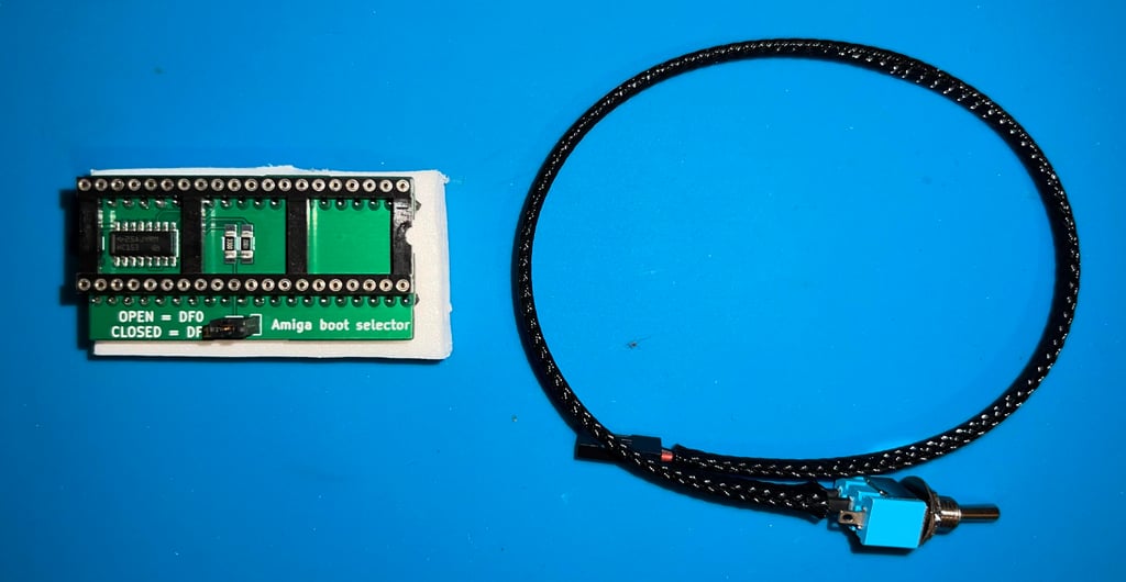
The DF0/DF1 switch is ordered from AMIGAstore.eu. As can be seen from the picture below the kit consists of a small boot selector PCB and a an extension cable and switch.
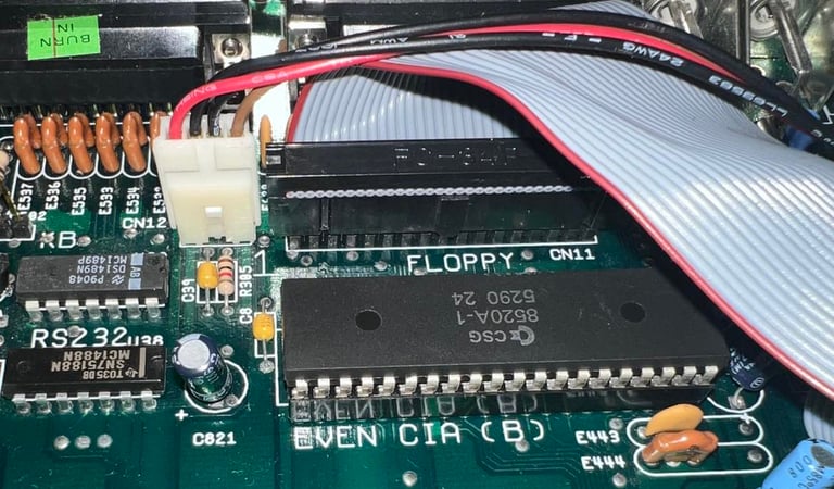
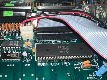
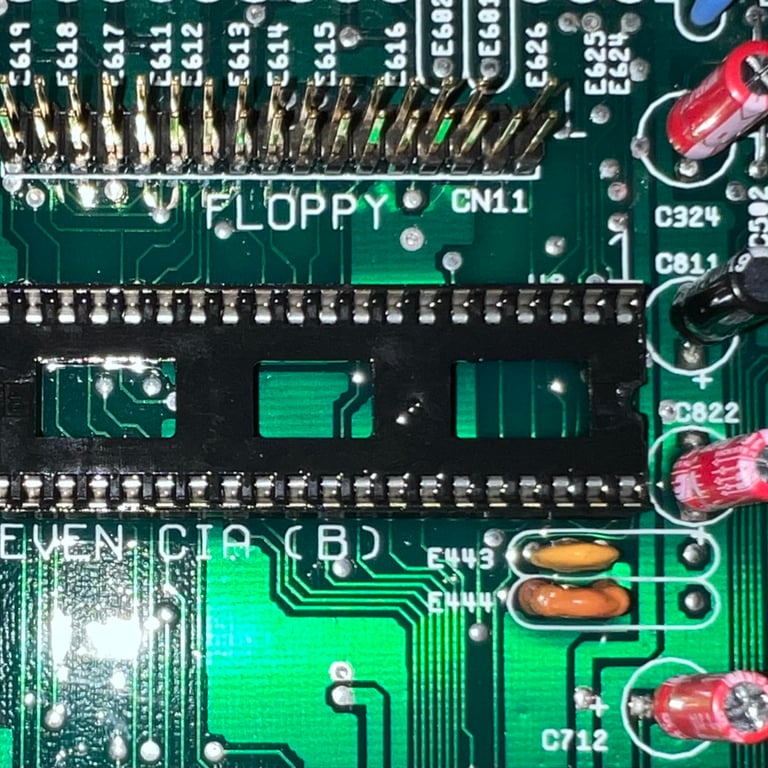
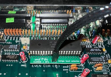
To install the boot selector the EVEN CIA is removed with a chip lifter. The socket is then rinsed with electronic cleaner and the boot selector is placed in the EVEN CIA socket. Finally the EVEN CIA chip is placed in the boot selector PCB socket. Note the position of the small notch in the chip and socket. Below are some pictures from this process.
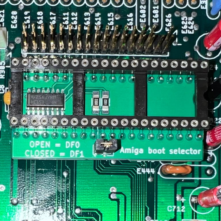
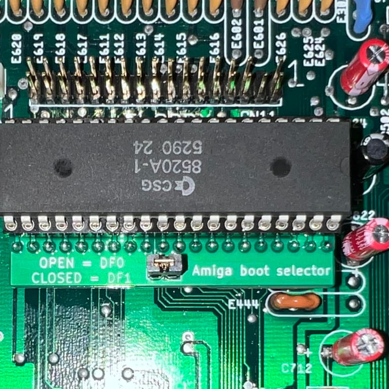
Finally the small jumper is removed and replaced with the extension cable and switch. Note that when the jumper is used the Amiga will boot DF1 and when the jumper is removed the Amiga will boot DF0. The switch will replace the function of the jumper.

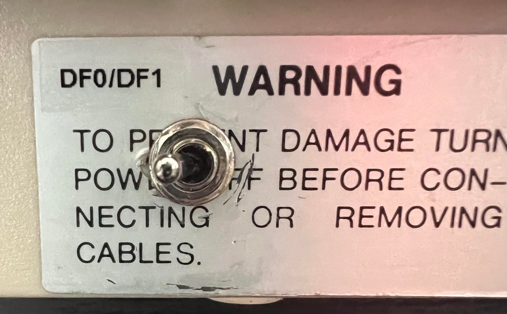
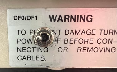
It turns out that there is a problem with the switch itself - the switch is constantly closed. Therefore a replacement switch is used (note that the boot selector works fine - it is only a mechanical problem with the switch itself). A small hole is drilled at back of the bottom cover and the switch is fastened here. Also, a small sticker is placed next to the switch so that it easy to see which position boots DF0/DF1.
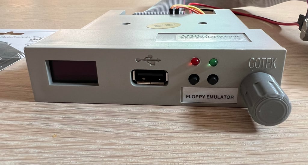
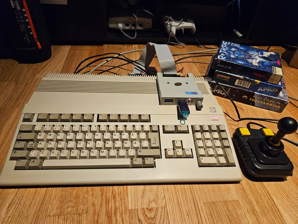
External Gotek drive
With an external Gotek drive and a DF0/DF1 you can keep the Amiga "as original as possible" - and at the same time enjoy the ease of having all of your great software on a simple USB stick instead of old floppies.
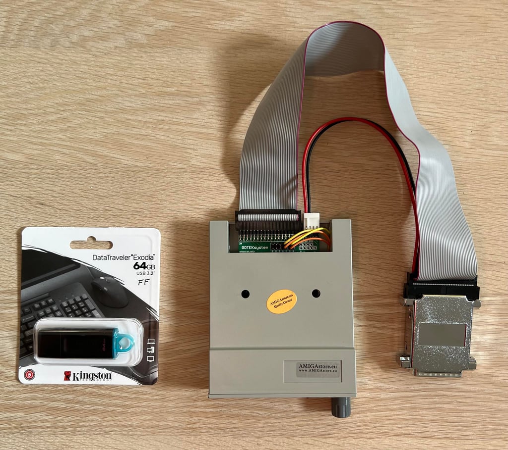
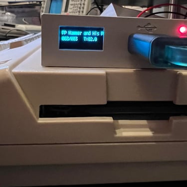
A package with external Gotek drive (OLED/Buzzer/rotary), pre-configured 64GB USB stick and all required cables and connectors are ordered from AMIGAstore.eu.
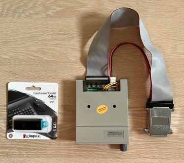
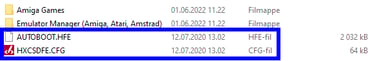
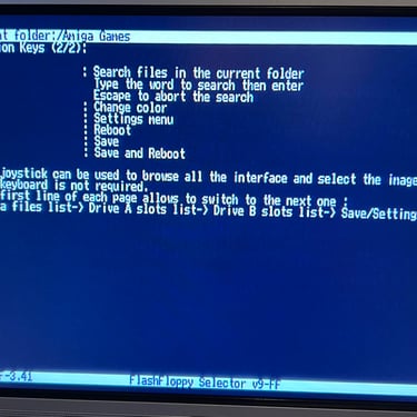
The USB stick is pre-configured with a few Amiga games and two important files which are required for the Gotek to boot. You can place your demos/games everywhere you want, but the two config files (see blue square in picture below) need to be in the root folder on the USB stick.
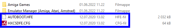
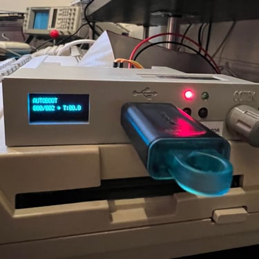
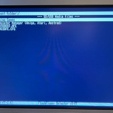
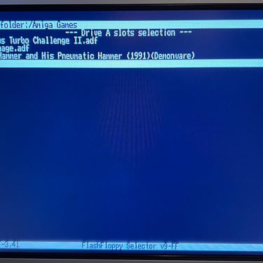
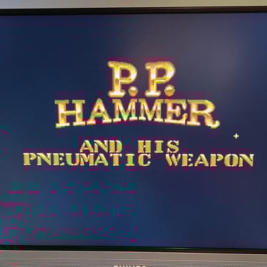
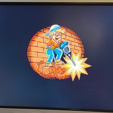
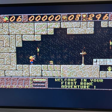
Some games are downloaded for testing purposes (https://tosec.ikod.se/ - note that I do not take any responsibility for any legal rights) and placed on the USB stick. To access the Gotek boot menu the selector needs to be set to "AUTOBOOT" and then reboot the Amiga.
Below are some pictures and a video from testing the external Gotek (DF0/DF1 selector set to "DF1").

Testing
Now it is time for testing the whole machine. All parts such as keyboard, RAM expansion, keyboard and disk drive have been tested in isolation, but now I will try to test "everything". How? Well, I basically to this in two stages:
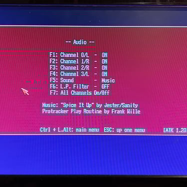
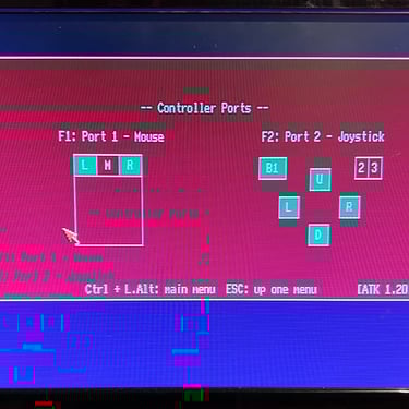
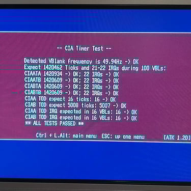
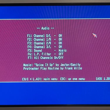
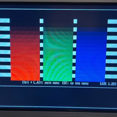
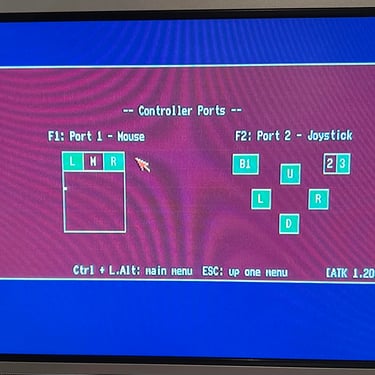
Formal testing with the Amiga Test Kit 1.20 (ATK). This will test most of the basic parts such as memory, floppy drive, video, audio, CIA, mouse, joystick and keyboard.
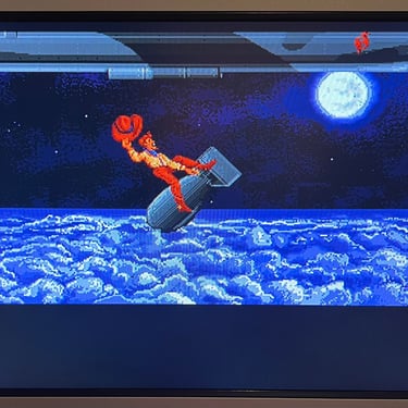
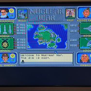
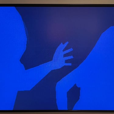
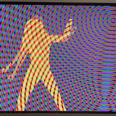
"Real usage" testing. I will basically use the machine playing games, watching and listening to demos and use the machine in regulator operation. This will detect flaws not easily detected with the ATK 1.20.
Below is a gallery from the final testing.

Final result
"A picture worth a thousand words"
Below is a collection of the final result from the refurbishment of this Amiga 500. Hope you like it! Click to enlarge!


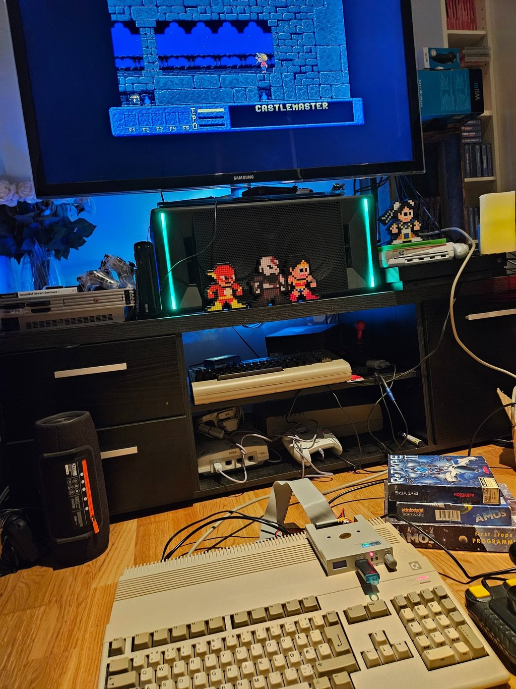
"Are you keeping up with the Commodore? 'Cause the Commodore is keepin up with you!"
Below are some pictures of the Amiga 500 back at the customer´s home!

Banner picture credits: Ajne01