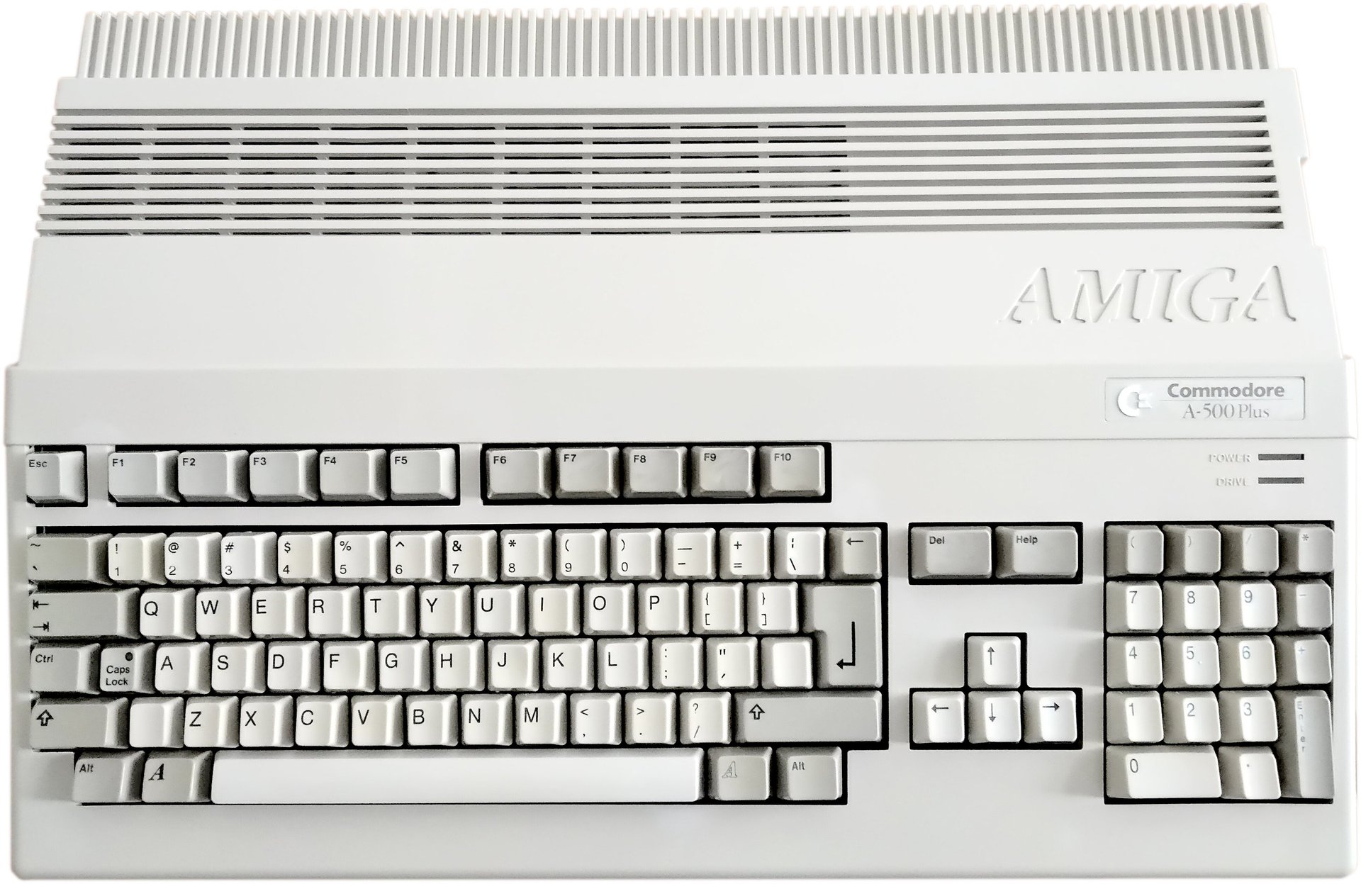
Amiga 500
Ser. No. Unknown
Assy 312510
Artwork 312513 REV 6A
Starting point
This special Amiga 500 is in for some refurbish, primarily some re-capping of the mainboard. But who knows, maybe I will find other areas that needs (or should) be improved to make this Amiga 500 as good as possible.
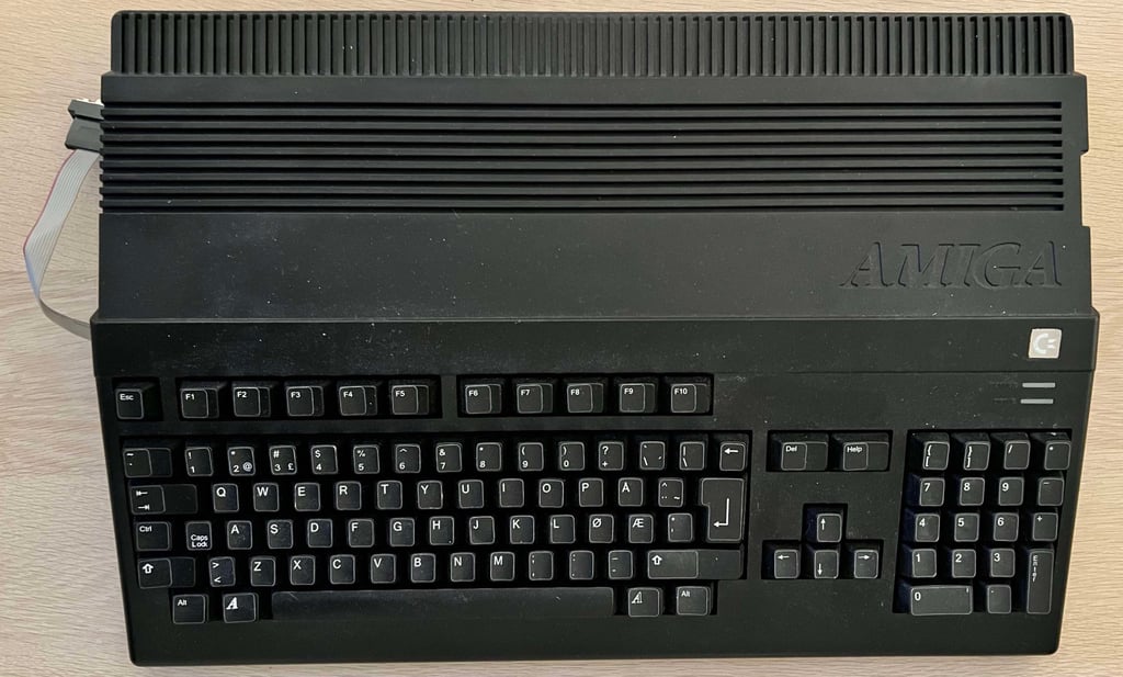
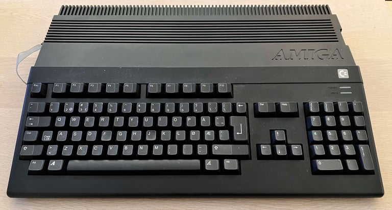
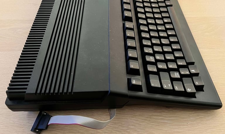
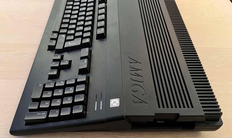
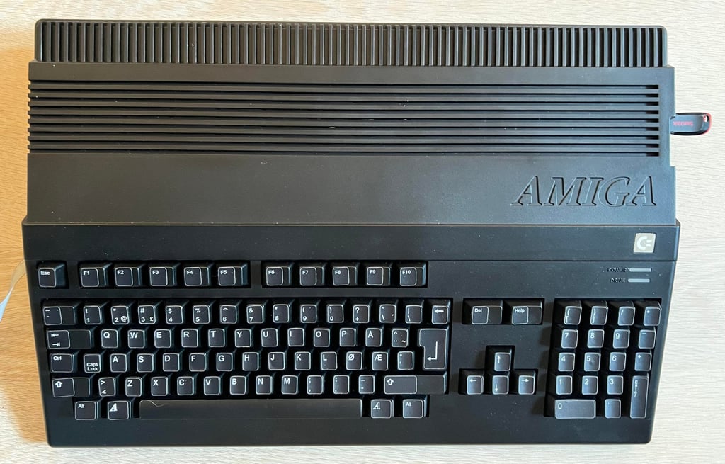
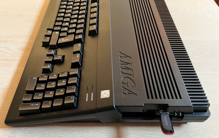
When I first heard that the machine was spray painted black I was quite concerned on how it looked. But, I must admit that the spray paint job is quite well done. Both the top- and bottom cover are painted black. And also the keycaps are painted black, with new stickers placed on each keycap. All-in-all I think this is a decent looking machine.
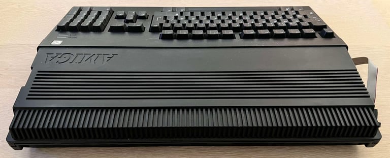
I can see that there are some dust and grease on the covers and under the keycaps, but not too bad. The covers are modified to fit a Gotek drive so that the display is more visible, and the USB connected easier to reach. There are other ways of installing a Gotek which does not require any modifications to the covers - by removing the Gotek casing and using special 3D printed adapters. Nevertheless, the job modifying the covers are quite ok. Only thing which might be something to look into is that the Gotek drive feels a bit looks and wiggly.
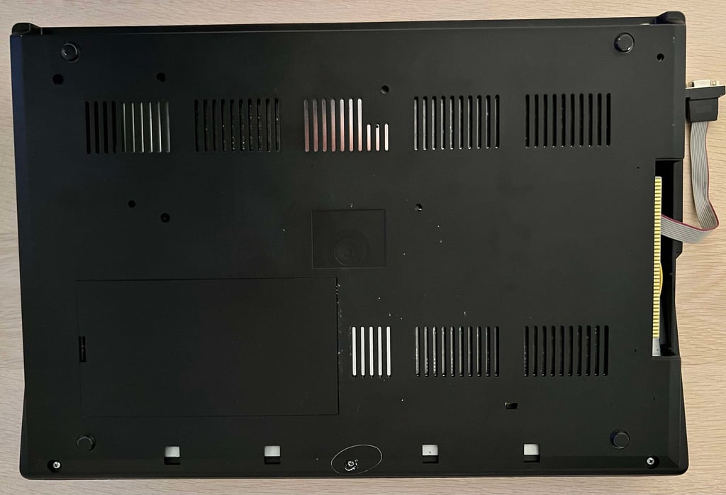
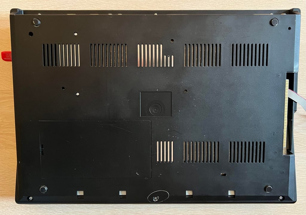
There is not sticker at the bottom cover informing about the model and serial number. Was probably removed during the paint job.
On the left side of the machine a flat cable, with a VGA connector attached at the end, is coming out from the side panel. There is obviously some analog video output intended to be used with old PC monitors. Quite a nice feature I think! I have never tried any of these before.
All the screws at the bottom cover are present, but the warranty seal is removed (of course).
Below are some pictures of the Amiga 500 before refurbishment.






Refurbishment plan
To refurbish this Amiga 500 the plan is to do this trough the following steps (some of them in parallell):
- Clean and remove stains from the exterior top- and bottom cover
- Clean and restore the keyboard
- Refurbish the main board (cleaning, checking, repairing, replacing capacitors etc.)
- Check and secure Gotek installation
- Verify operation by testing
Disassembly
The first stage of disassembly is to remove the six screws located at the front and back of the bottom cover. These screws are 3 x 9 mm Philips. NOTE: On this Amiga ther are no screws holding the internal floppy drive (as there is none), but you want to wait with removing these anyway to avoid the drive falling out.
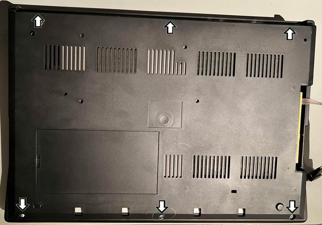

With the screws removed the front cover is carefully lifted away, and the inside is revealed. I notice a few things, which is not necessarily problematic but should be considered checked:
The left side of the RF-shield is bent upwards. This is probably to make room for the VGA adapter.
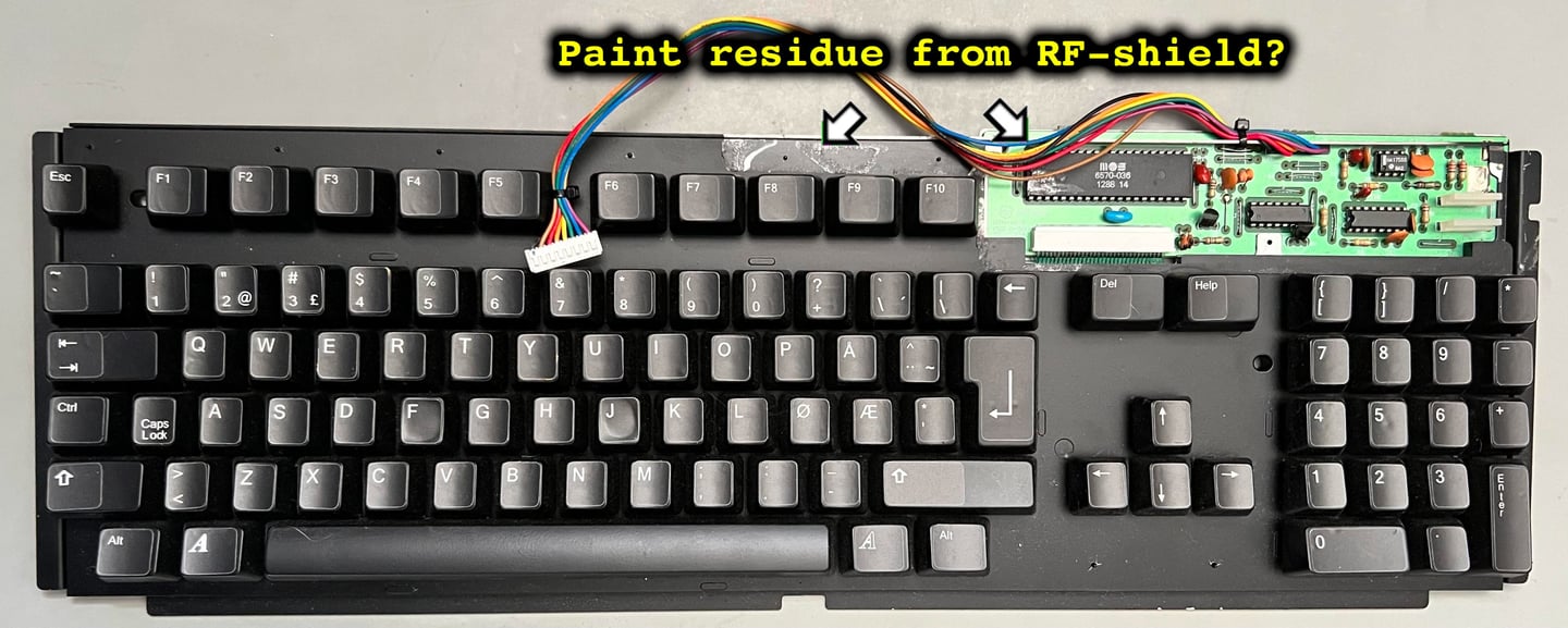
There are some paint (?) residue on the keyboard electronic circuitry
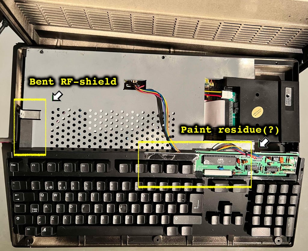

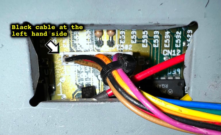
To remove the keyboard the connector is simply pulled (carefully) from the mainboard. NOTE: make sure to install the keyboard connector the correct way on re-assembly. Since the connector is NOT keyed there is a risk of installing it the wrong way. The black cable should be the first cable on the left hand side when the machine is seen from the front.

Now the complete RF-shield is visible. And it looks in very good condition (except for the bent parts). But now I notice that the RF-shield is partially painted. Could this be the cause of the paint residue on the keyboard? I assume the RF-shield has been painted to cover some early signs of corrosion. I can not see any signs of corrosion on the shield, so the paint job has been a success in that respect. But I don´t see why not the whole RF-shield was painted?
Also, notice that there is a 512 kB additional RAM in the expansion slot. So this A500 is able to run 1 MB games and demos. Nice!
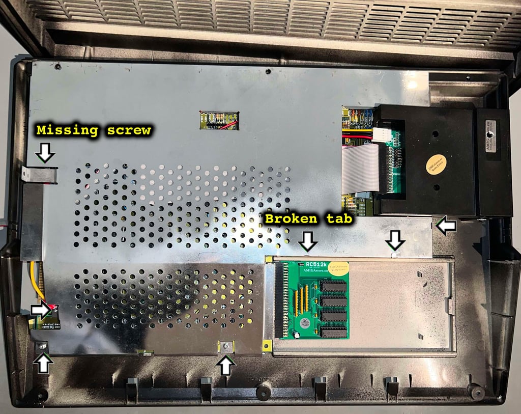

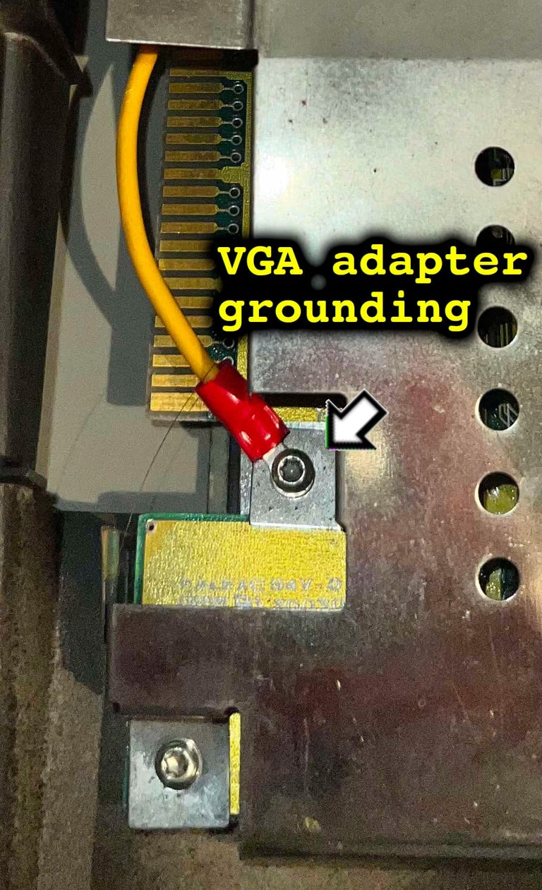
Next point of action is to remove the RF-shield by removing the three 3 x 8 mm T10 screws at the bottom left hand side (see picture above). Note that the fourth original screw is missing probably due to the installation of the VGA adapter. Also, not a big deal, but one of the metal tabs holding the RF-shield in place is broken off. NOTE: One important thing to notice is that the VGA adapter is grounded to the mainboard using one of the T10 screws. This is important to keep in mind when re-assembly.

There is only one small screw holding the internal Gotek in place. This is removed, and the Gotek drive is now only resting on the stand-offs.
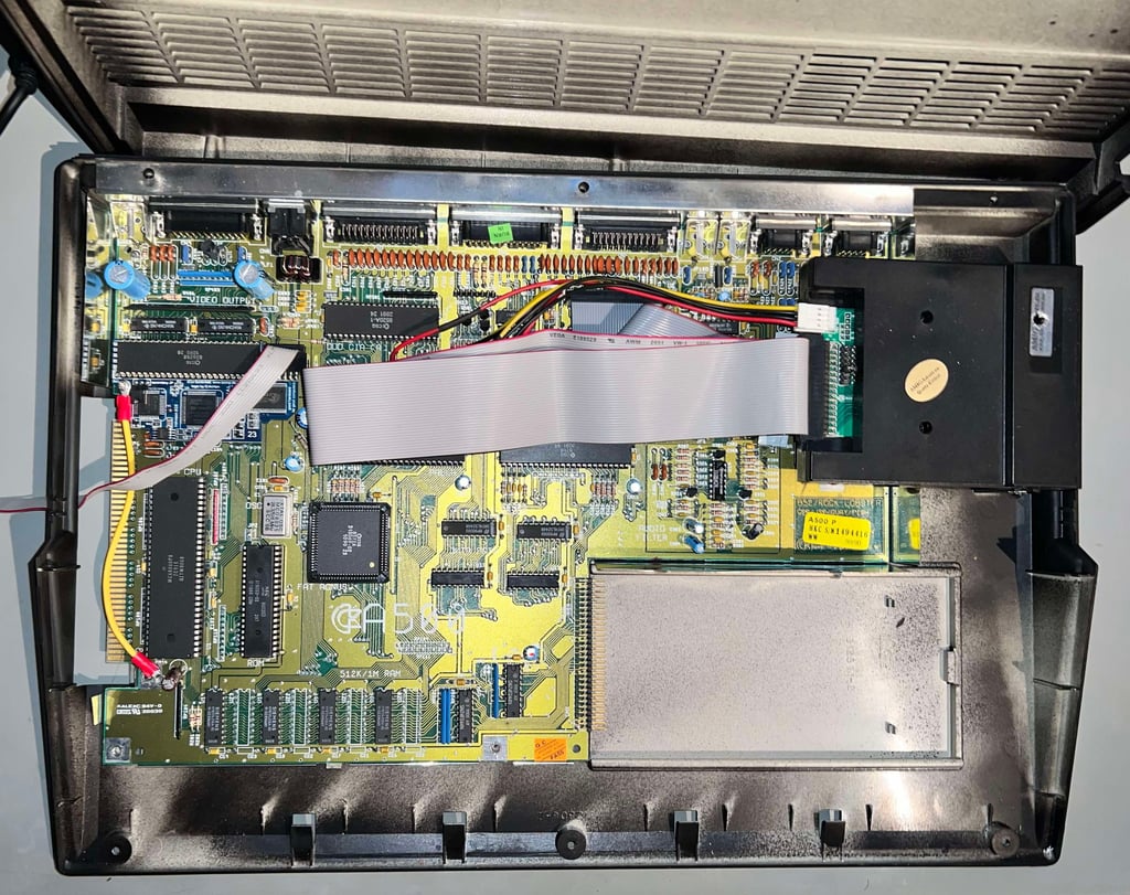

When the RF-shield is removed the PCB is revealed. And the first impression is quite good - it can not see any immediate damage or corrosion. And now we can see the VGA adapter and Gotek drive in all its glory.
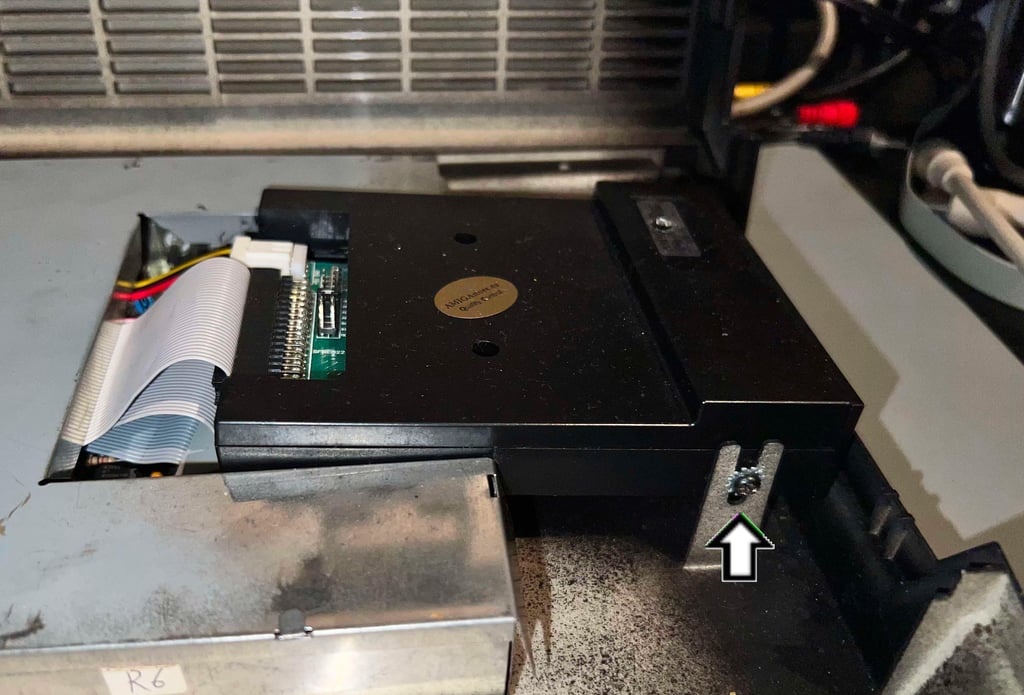

Both the data- and power connector are removed from the Gotek, and the drive is lifted from the PCB. Next step is to remove the PCB from the bottom shielding. There are 12 hex head bolts (5 mm) which have to be removed first.


Exterior casing
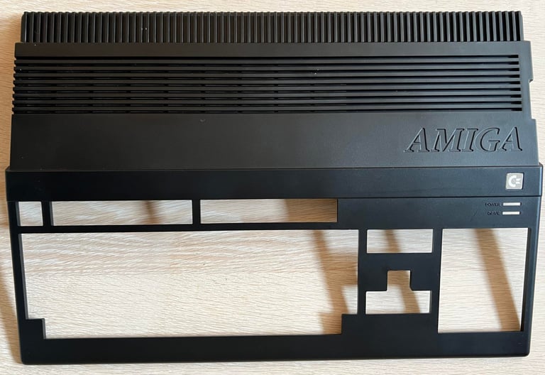
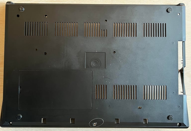
As mentioned the paint job is very well done I think - quite impressive. In the beginning I was quite sceptic seeing this non-original colour, but after working on this machine for quite some time I start thinking it is quite cool! The side cover is missing though, probably due to the VGA cable exiting the machine here.
Normally I soak the covers for several hours (or days). But I don´t do this with these. And it is not required either. Yes, there are quite some dirt and grease, but it is only a thin layer on the covers. So instead, the covers are cleaned with mild soap water for just some minutes. This do remove the dust and grease without any problems.
Below are some pictures of the covers after cleaning.


Keyboard
From the outside the keyboard looks to be in ok condition, but there are something I notice:
There is some "silver" / grey paint residue on the top of the metal bracket. Part of this paint residue has also spilled over to the MOS 6570-036 IC keyboard processor. Can this paint be from the RF-shield?
The "Enter" key on the numpad is sometimes stuck when pressed repeatedly.
There are some, but not massive, dust and grease beneath the keycaps.
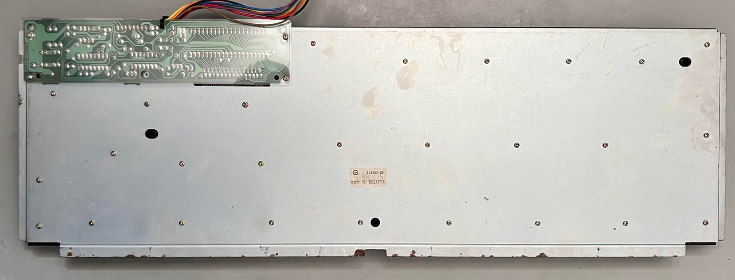
All the keycaps are painted black, and an individual sticker is placed on each one of them. As with the top- and bottom the the paint job is quite well done.


Initial test
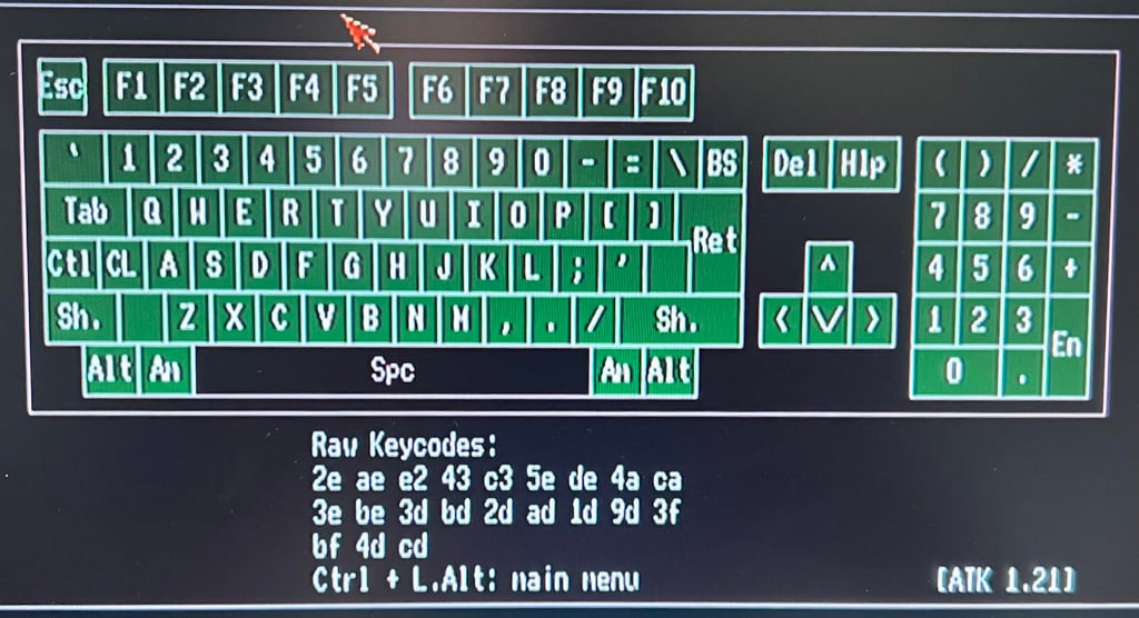
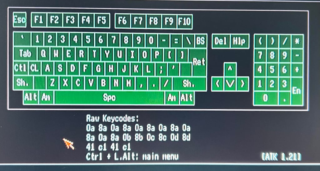
A great tool for testing the keyboard is the Amiga Test Kit. With this tool all the keys can be tested, and the with the visual presentation from the software it is easy to detect if a key is non-functional og marginal.
The test shows that all the keys works fine... except for for the spacebar key.

Faults investigation
It is very common, unfortunately, that the Amiga 500 is malfunctioning after almost 40 years. There are two main reasons why the keyboard can malfunction:
Contaminated plungers. The conductive rubber at the end of each plunger can have a thin layer of grease preventing them for functioning.
Defective membrane. The Amiga 500 membrane is very thin, and it is very common that traces are broken due to corrosion.
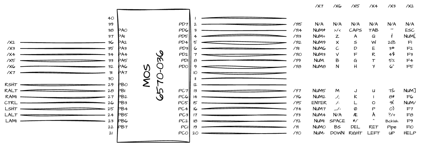
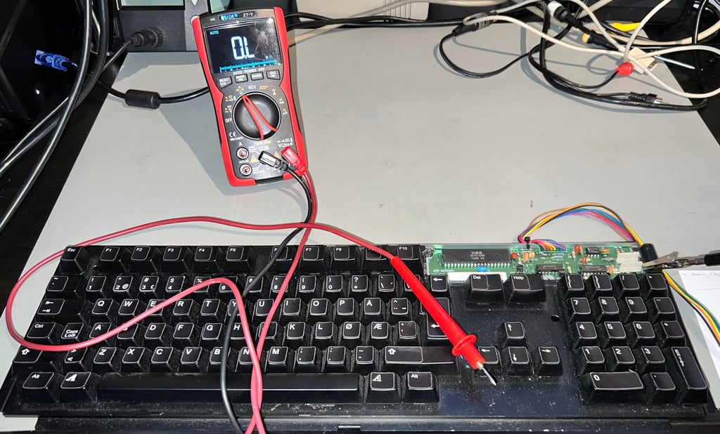
A way of checking whether or not we are dealing with at defective membrane, or a plunger with a too resistive conductive rubber is to use a multimeter in Ohm-mode and measure directly on the MOS 6570-036 keyboard processor. The schematics below show how the keyboard matrix is connected to the IC (the schematic is based on the information found in the EAB forum).

The testing is done by:
The ground cable on the multimeter is connected to rightmost jumper located on the PCB
The other multimeter cable is placed on the different pins presented (PBx, PCx and PDx) in the schematics above
While the multimeter is in Ohm mode the keys connected to the current pin are pressed down one-by-one
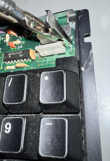


In the table below the expected measure range is shown. The spacebar is connected to pin 18 (PC2).
When performing this test it becomes clear that the membrane is probably - in the context of a trace to the spacebar. When pressing the spacebar while measuring the result is infinite Ohms. If the plunger was marginal I would expect some high measure, but there are no signs of life when pressing the spacebar key.
Disassembly
To disassembly the keyboard all the keycaps are removed first. This is done by using a specialised keycap puller. It is highly recommended to use such a specialised tool - this will reduce the risk of damaging the keycaps and the plungers. Notice that under each keycap there is a small spring, and beneath the spacebar there are two additional smaller springs.
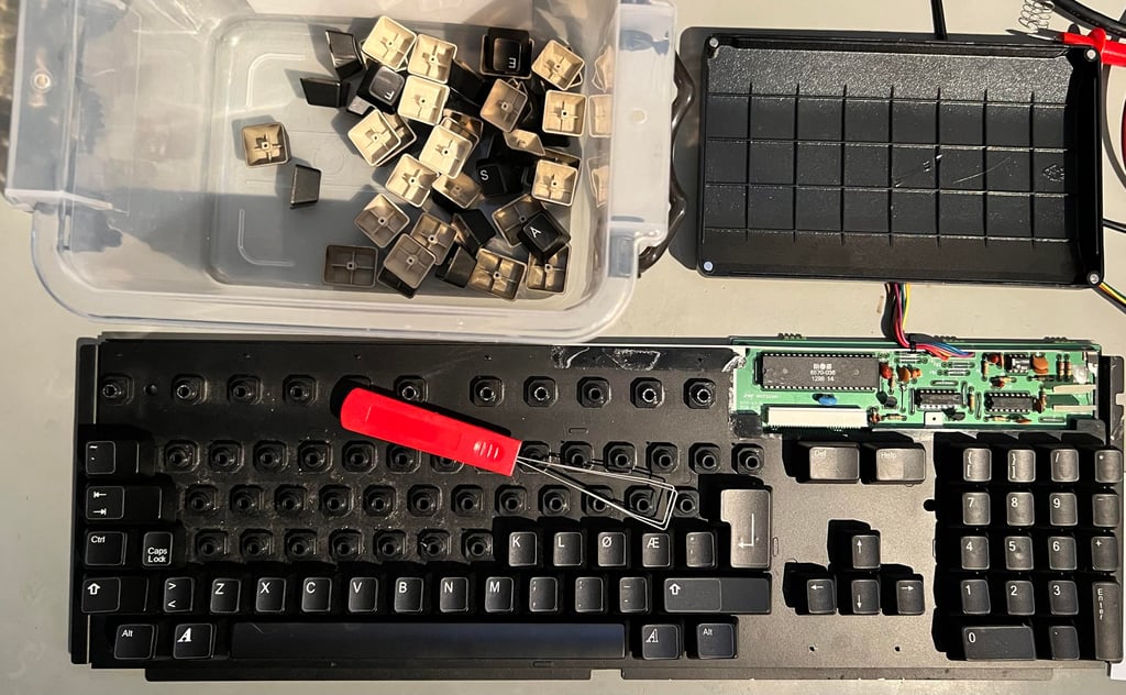

Next step is to start removing the keyboard PCB. There are four screws holding the PCB to the metal bracket which must be removed. Note that one of the screw (the one with the washer/spacer) is actually placed beneath the transparent shield. Also, the small cable tie must be cut.
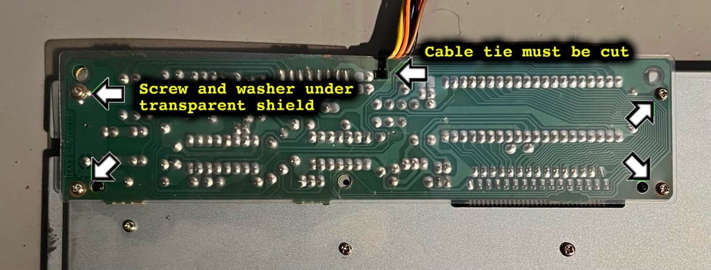

Before the PCB can be removed the flat cable connector needs to be opened. This is done by pushing each side of the cable connector downwards. When the connector is pulled down, the PCB can be carefully wiggled out of the flat cable connector.
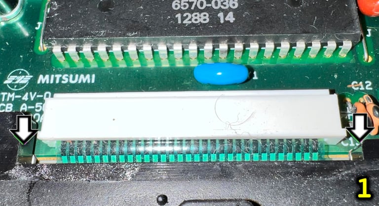

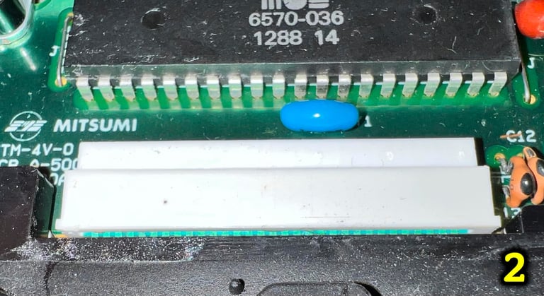

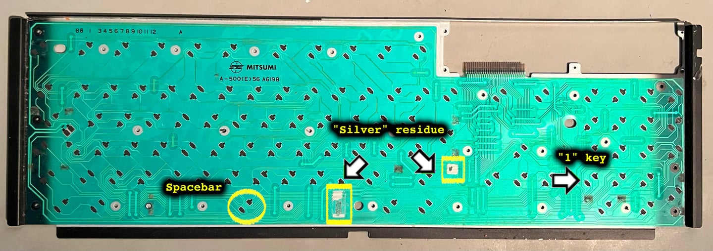
All the small screws at the backside of the keyboard are now removed, and the top metal bracket (with all the plungers) are lifted away. The thin membrane is now visible. This is a standard Mitsumi A-500 (E) 56 A619B fleksible membrane PCB very common in many A500 machines.

Checking the keyboard membrane
The membrane is quite dirty and sticky. There are several areas which have accrued dirt and grease. With a multimeter the resistance between the lower part of the spacebar pads and the numerical "1" key is measured. And, no surprise, there is no connection at all. There is a broken trace between these two pads which should be connected.
And I think I see the cause of the problem straight away. There are two square looking areas where some same (?) silver residue are stuck on the membrane. It is very likely that this residue have corroded the trace(s).
With a moist Q-tip the "silver" area is carefully cleaned. And with no force at all the traces just disintegrates. The paint has eaten away the traces leaving a broken traces behind... See pictures below.
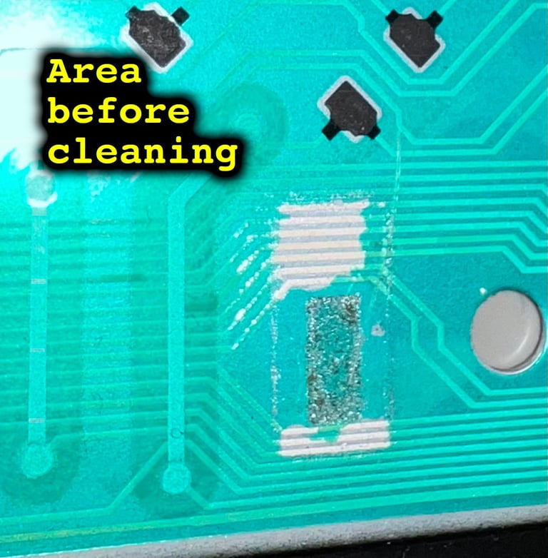

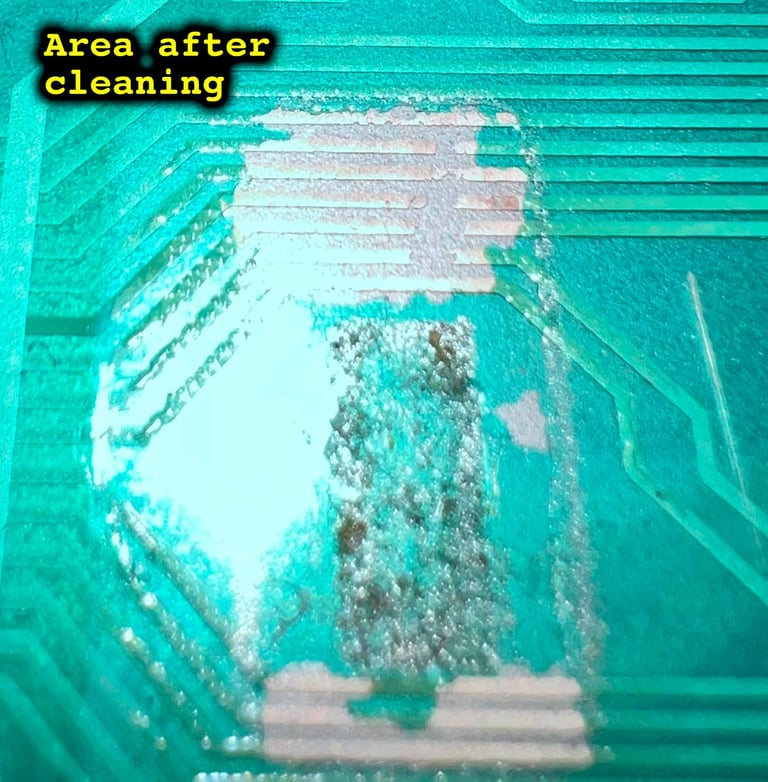

The same silver paint (?) can be found on the plunger plastic bracket. This is the cause of the malfunctioning membrane. The silver paint have somehow gotten into the keyboard near the spacebar and the return key. And this paint has then flown on to the membrane and caused damage.
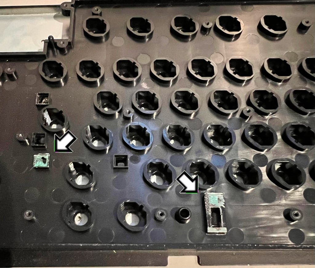

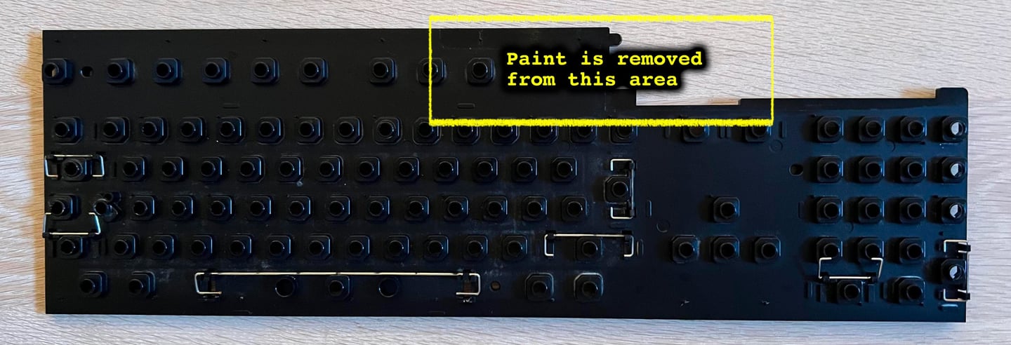
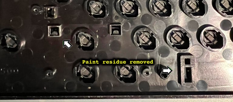
When working with the plastic keyboard bracket I notice that the front is in fact spray painted, could it be this paint that has soaked to the bottom of the bracket? What I at first thought were dust and grease is paint residue. The paint job is quite well done I think, the only thing I "fix" on the front side is to remove some part of the paint from the top right area (see square in picture below). To remove the paint a small amount of the Norwegian oil-thinner White Spirit is used. Then the area is cleaned with isopropanol.
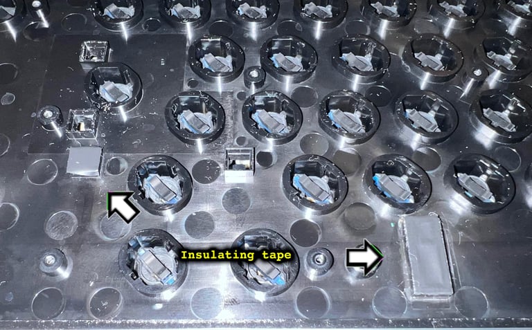
At bottom side of the bracket the two areas which were contaminated with the paint are thoroughly cleaned. In addition a small piece of black insulating tape is cut to cover the two most contaminated areas. This is just to prevent tiny amount of residual paint to corrode and damage a new membrane. Below are some pictures of the plastic bracket after cleaning.



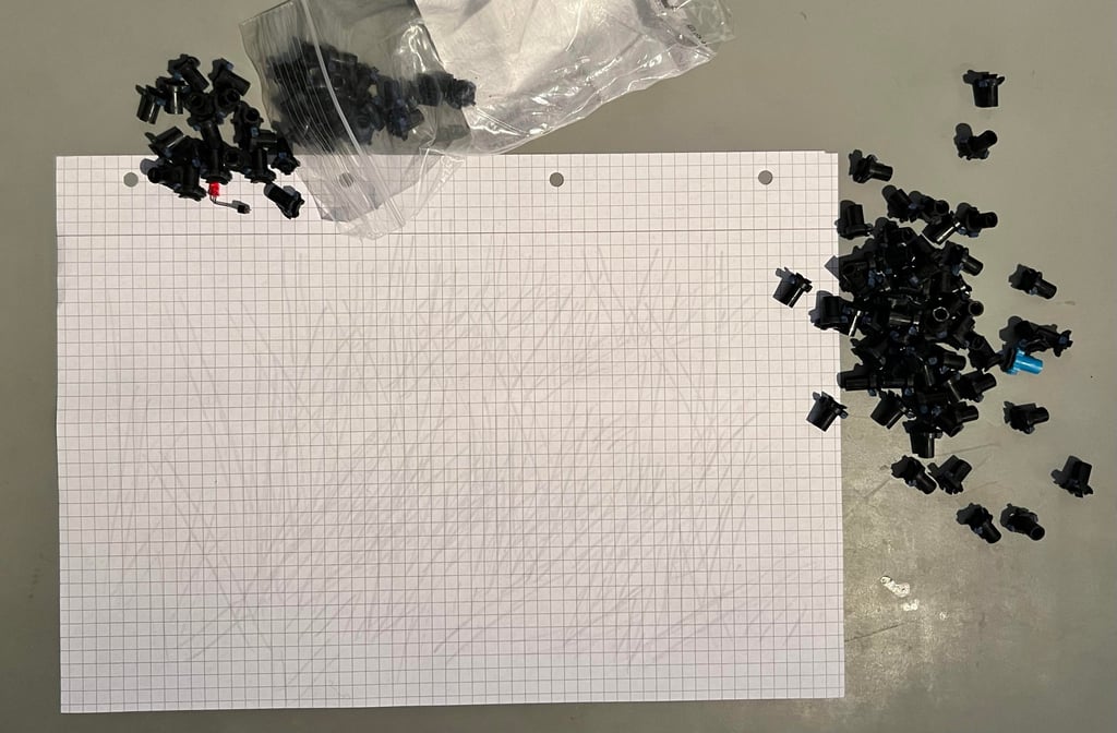
Before all the plungers are re-installed they are carefully rubbed against a clean sheet of paper. This will remove any grease and dust that could contaminate the conductive rubber located at the end of the plungers. That way the keypresses will be way more responsive since no additional grease add up resistance to the conductive rubber.

Inspecting and cleaning the keyboard PCB
The keyboard PCB is a common Mitsumi MTM-4V-0 / PCB A-500 56 A620A. There are quite some dirt, grease and paint residue on the PCB. But besides that, I can not see any signs of damage. Both the ceramic- and tantalum capacitors appear to be in good overall condition.
Some isopropanol and a Q-tip are used to clean the PCB. Below are some pictures of the keyboard PCB after cleaning.


Replacing the keyboard membrane
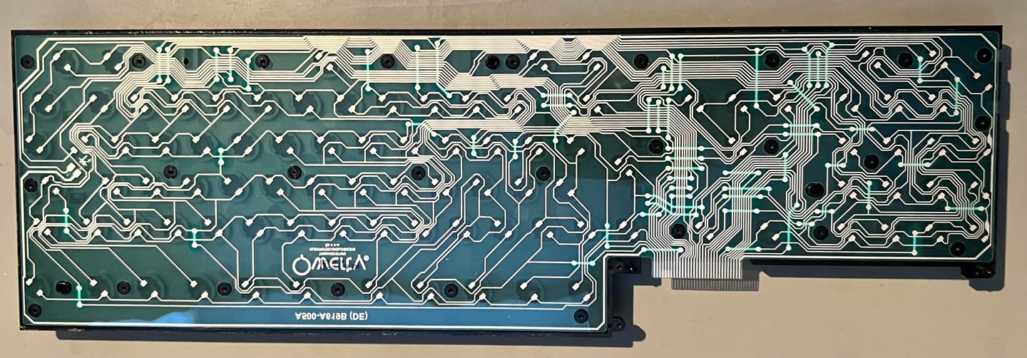
The original keyboard membrane is beyond repair. A new one is ordered from AMIGAstore.eu This a replica of the original Mitsumi A-500 (E) 56 A619B flexible membrane. See picture below.


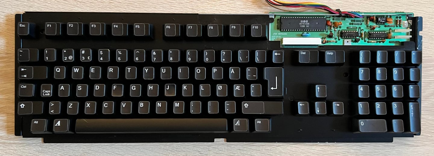
Replacing the membrane is straightforward. The membrane is placed resting on all the plungers, and then the keyboard is assembled.


Testing
A quick test is done using the Amiga Test Kit, and the keyboard testing feature. All keys are registered correct. Note: there is a bit of a "squeaky" feeling when pressing the "0" key. The plunger is probably rubbing the plastic frame slightly. Nevertheless, I think it is better to leave it like this to avoid risking any damage.

Mainboard
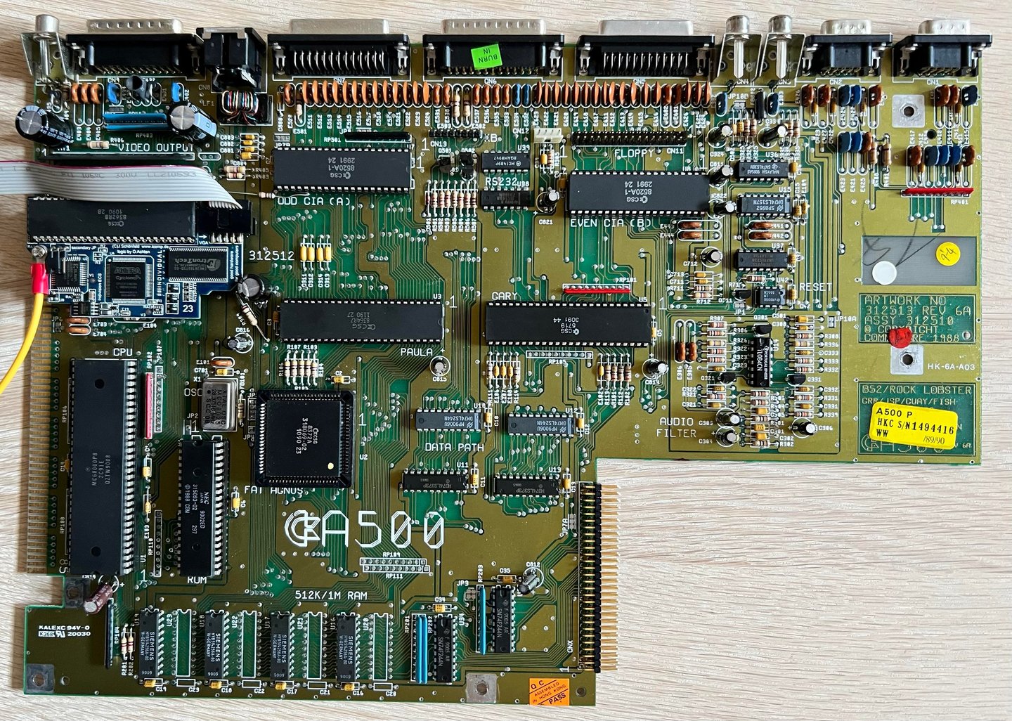
This mainboard is the Assy 312510/Artwork 312513 Rev 6A. Probably most known for the Fat Agnus (8372A) capable of addressing 1 MB of Chip RAM.
Visual inspection
The mainboard appears to be in good condition. I can not see any major signs of damage, but there are some areas which needs to be checked further:
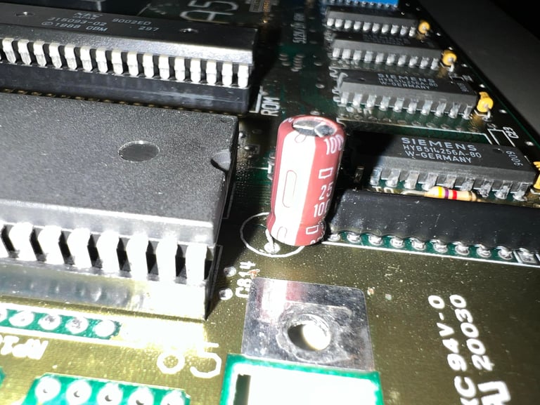
The electrolytic capacitor C814 appears to be replaced previously. It is of a different brand (see arrow front PCB) and clear marks of flux residue (see bottom right arrow at the backside of the PCB).
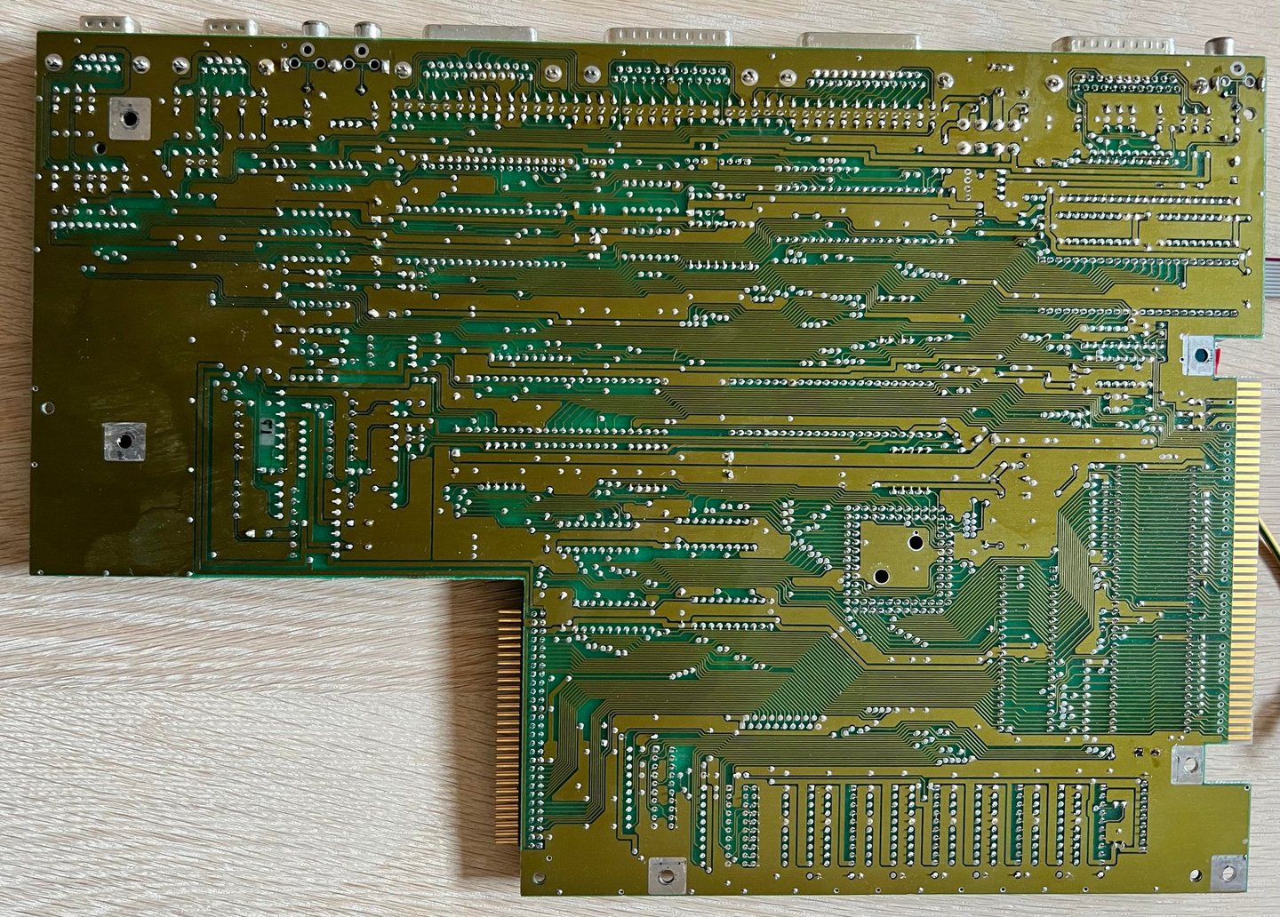
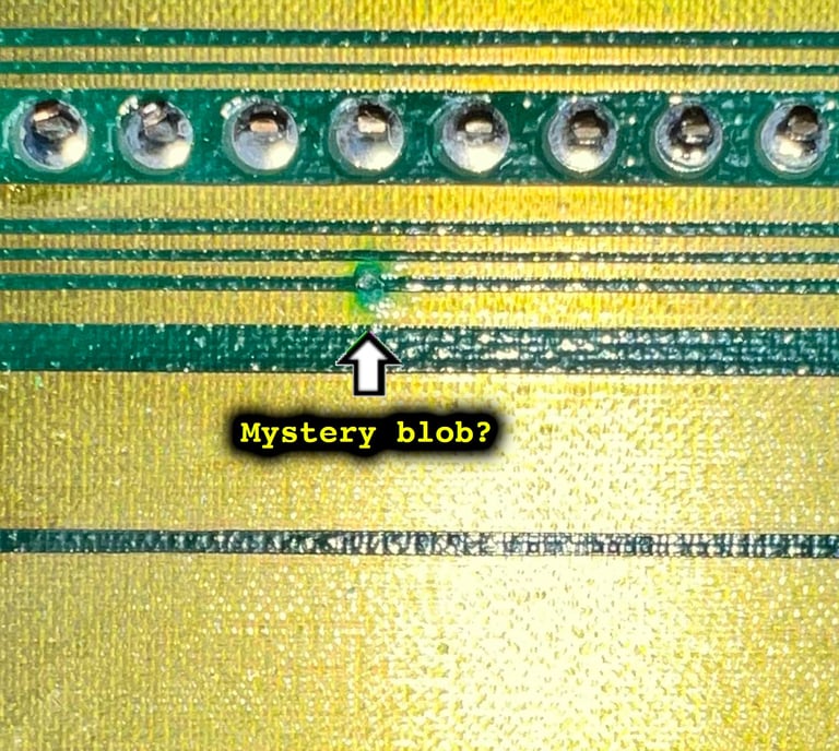
There is a tiny "blob" of some dark unknown material covering some one the traces on the backside of the PCB (see center arrow in the picture blow). The "blob" is really hard, feels almost like concrete (?), and it not possible to remove with just isopropanol. This is something that need to be checked further.
As can be seen from the pictures below the mainboard is equipped with a modern upgrade - an adapter from Individual Computers which extends the Denise chip to allow for VGA video output.
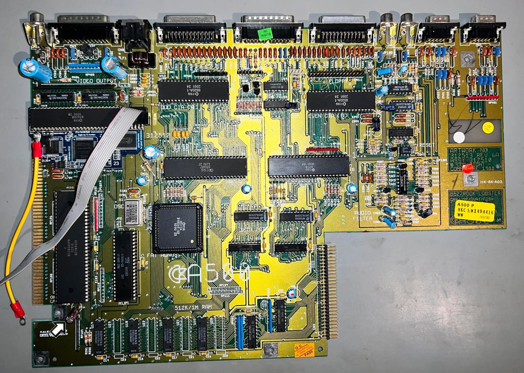

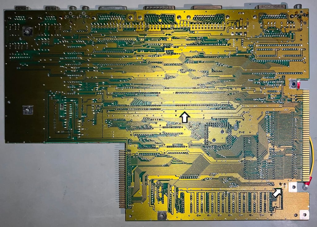

All the custom ICs are listed in the table below. There is something interesting to notice here:
The GARY and CIAs were manufactured in mid 1991. But the remaining custom ICs, and also the RAM, we manufactured early 1990 - almost 1.5 year earlier.
The keyboard controller mounted not on the mainboard, but on the separate keyboard PCB, have the custom IC manufactured early 1998.
Either this machine have been repaired at some time by changing the Gary and CIAs, or Commodore used whatever parts they had laying around. It is also a possibility that a partly pre-populated PCBA was used and completed by adding the Gary and CIAs. What about the keyboard? My best guess is that this is not the original keyboard shipped with the machine in the first place. But at some time replaced with another. Nevertheless, this is all guessing. Maybe I find some more clue later while refurbishing?
Checking the voltages
Even if the machine powers on without any issues it is good practice to measure the voltages - to verify that all voltages are present and within tolerances. Voltages which are not within acceptable tolerances are often a symptom of faults (just like a doctor would check temperature and blood samples).
As the table below show all voltages are present and ok. Note that this table will be updated after completing the refurbish.
Replacing the electrolytic capacitors
Although not common on the Amiga 500 it can happen that old electrolytic capacitors have dried out, and as a consequence have altered their capacitance. Therefore it is good practice to replace these. According to the capacitor list, the assy 312510 / artwork 312512 Rev 6A mainboard are equipped with 17 electrolytic capacitors. The owner has supplied the required capacitors (these were bought in advance from one of the well known Amiga spare spart web shops).
Replacing the electrolytic capacitors can be a bit tricky on the Amiga 500 PCB due to its large ground plane which consumes a lot of heat. I recommend spending some time on the desoldering process to avoid damage on the mainboard, and following these "rules of thumbs":
Add fresh solder on the points to be desoldered
Set solder (and de-solder) temperature to 350 degrees Celcius for non-ground plane points
Set solder (and de-solder) temperature to 390-400 degrees Celcius for ground plane points
If the ground plane solder points don´t clear up try add some more solder and then "wiggle" the capacitor loose. Then repeat process.
No trace or pads were damaged during soldering and de-soldering.
Some remarks from the re-cap process:
Some of the supplied capacitors does not match the original voltage ratings: new voltage ratings are higher than the original. This applies for C303, C304, C324, C334 [35 V -> 50 V] and C807, C821 and C822 [16 V -> 25 V]. This is fine since the new voltage ratings are higher than the original.
Some of the supplied capacitors does not match the original voltage ratings: new voltage ratings are lower than the original. This applies for C306 and C712 [50 V -> 35 V]. This is fine since the new voltage ratings actually are correct according to the original PCB design. Commodore often "whatever they had available" at the time of manufacturing, and sometimes used higher voltage rated capacitors.
As mentioned one of the electrolytic capacitors was already replaced: C814 [100 uF / 16 V]. This capacitor looks perfectly fine so I do not replace this to avoid the risk of damaging any traces or pads (I do not know which temperature was used during this process). Below is a picture of the capacitor C814.

Below is a picture of the mainboard with the new capacitors in place.


Repair - mystery blob
During visual inspection I notice the "mystery blob". Beneath the Paula IC (on the bottom side of the PCB) there is a small, very hard, concrete-like blob. My guess is that some moist from the bottom side of the machine has gathered around some dust. And during the years the dust has turned into something very hard material.

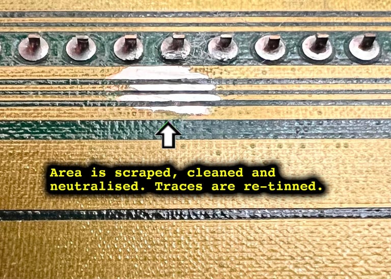
It is not possible to remove the blob with isopropanol. So instead, the area is scraped with a combination of sharp pick tools and a thin flat screwdriver. Also, some vinegar is applied removing any alkali residue from the blob. The complete area is cleaned with isopropanol and re-thinned with solder. This should prevent any further corrosion.

Securing and improving the Gotek installation
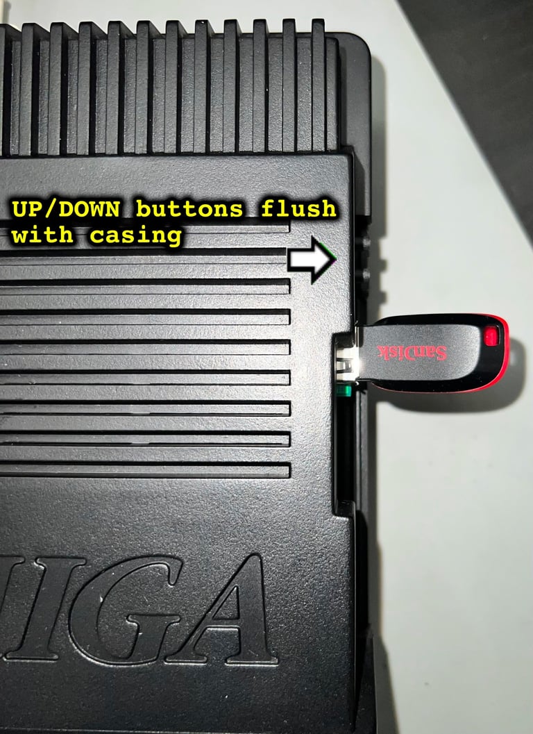
The Gotek drive is quite loosely mounted in the Amiga 500, and the UP/DOWN buttons are somewhat difficult to reach. The latter is mostly related to user experience, but the former can be a problem. If the user is actively using the USB stick, and the UP/DOWN buttons, there is a risk that the loose Gotek can cause damage inside the machine.
Therefore a 3D printed bracket, with new stand-offs and screws, are prepared. This will both properly secure the Gotek inside the machine, and also the user experience should be improved as the UP/DOWN buttons (and display) are more reachable.
For this Gotek there is a predesigned 3D file available at Thingiverse (credit: _CrazyBob_). Both the main bracket and the stand-offs are printed in black material.
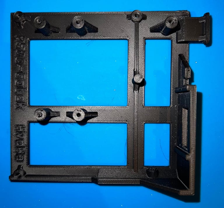

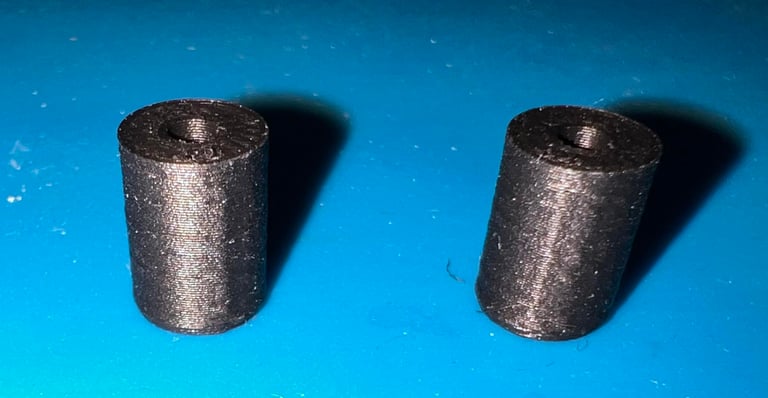

The bracket, and stand-offs, are installed in the Amiga 500. Notice that on the rear stand-offs there are 3 x 10 mm Torx screws on both the top side of the bracket, and also from the underside of the bottom cover. See picture below.
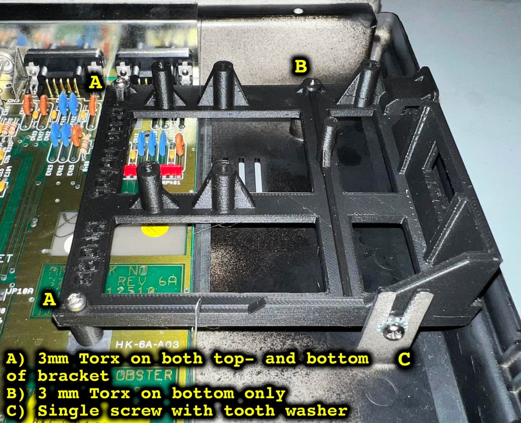

Disassembly the Gotek drive is straightforward. The three screws at the top cover are removed, and the cover is lifted out. The interior PCB, and the LED display, are wiggled loose from the bottom cover and lifted.
Installation of the interior Gotek is done by:
The PCB is placed above the six supporting stand-offs on the bracket. Two of these have small pins which are used to align the PCB in the correct position, one is for support only and three of them have screw holes to fasten the PCB. For the latter, three 3 x 10 mm torx screws are used to secure the PCB to the bracket.
The two LEDs (red and green) are actually not used as the LED drive light on the Amiga does this, but they are carefully bent backwards towards the interior of the Amiga. As a short circuit precaution some insulation tape is placed on the PCB.
The LED display is snapped in place in the bracket. This will hold the display in place.
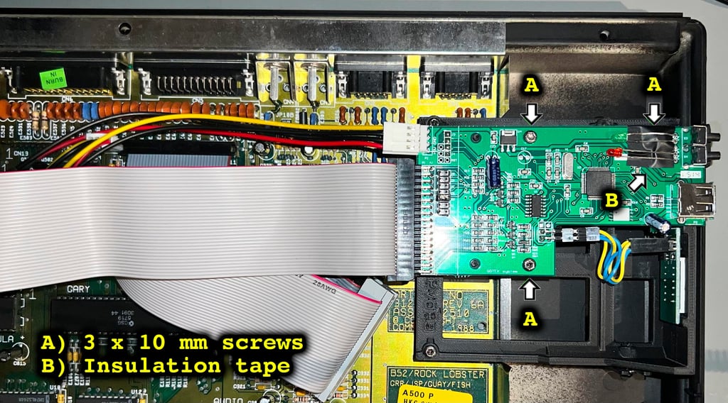

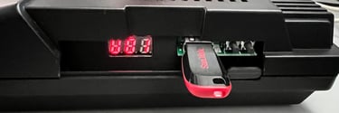
After installation and re-assembly the Gotek is now firmly seated. The UP/DOWN buttons are easy to use, the Gotek doesn´t wiggle, the USB is tight and the LED display is visible. Below are some pictures taken from above and from the side.


Testing
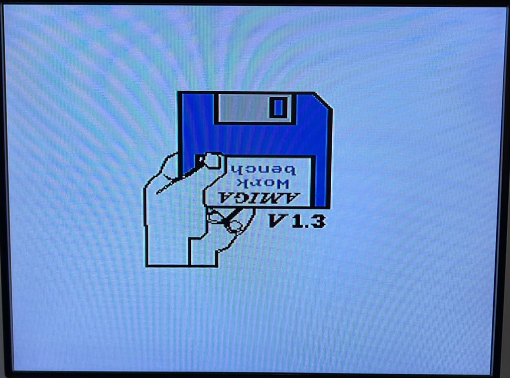
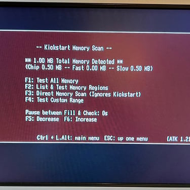
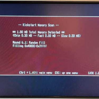
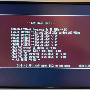
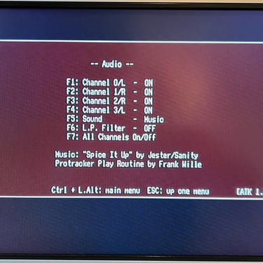
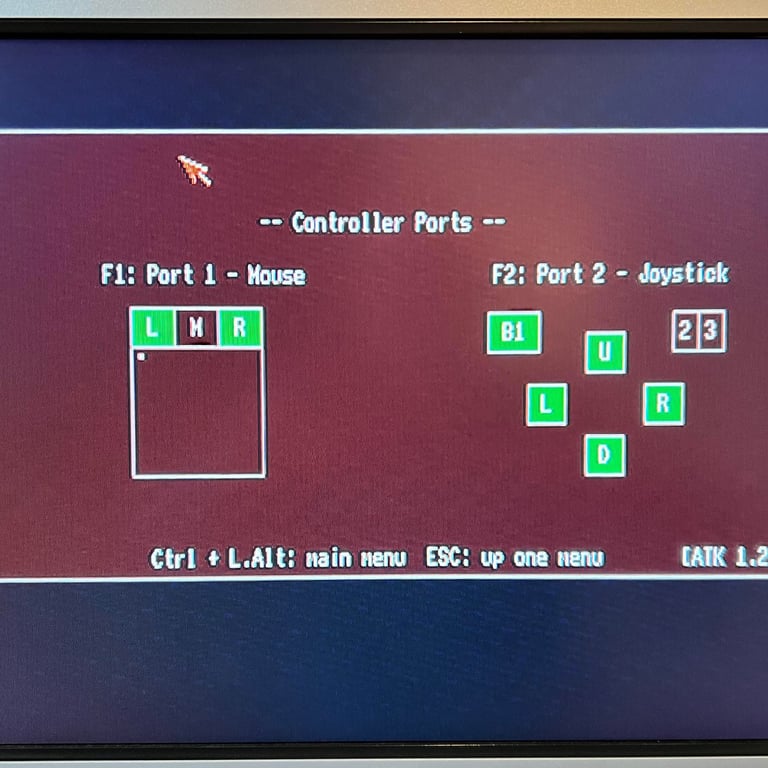
Now it is time for testing the whole machine. All parts such as keyboard, RAM expansion, keyboard and Gotek have been tested in isolation, but now I will try to test "everything". How? Well, I basically to this in two stages:
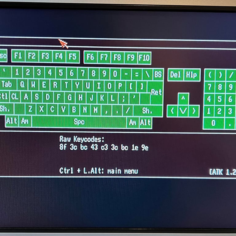
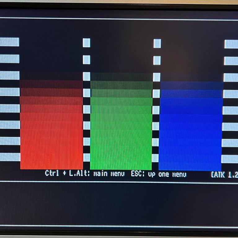
Formal testing with the Amiga Test Kit 1.20 (ATK). This will test most of the basic parts such as memory, floppy drive, video, audio, CIA, mouse, joystick and keyboard.
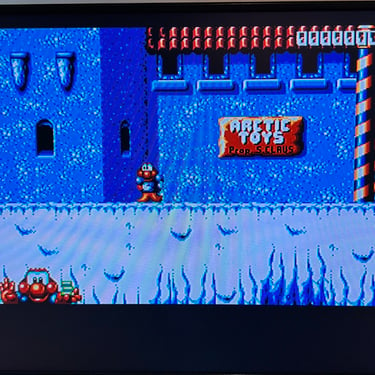
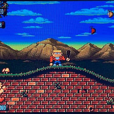
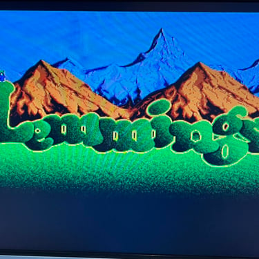
"Real usage" testing. I will basically use the machine playing games, watching and listening to demos and use the machine in regulator operation. This will detect flaws not easily detected with the ATK 1.20.
Below is a gallery from the final testing.



Final result
"A picture worth a thousand words"
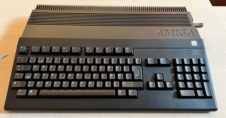
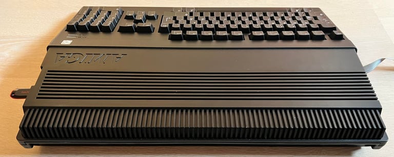
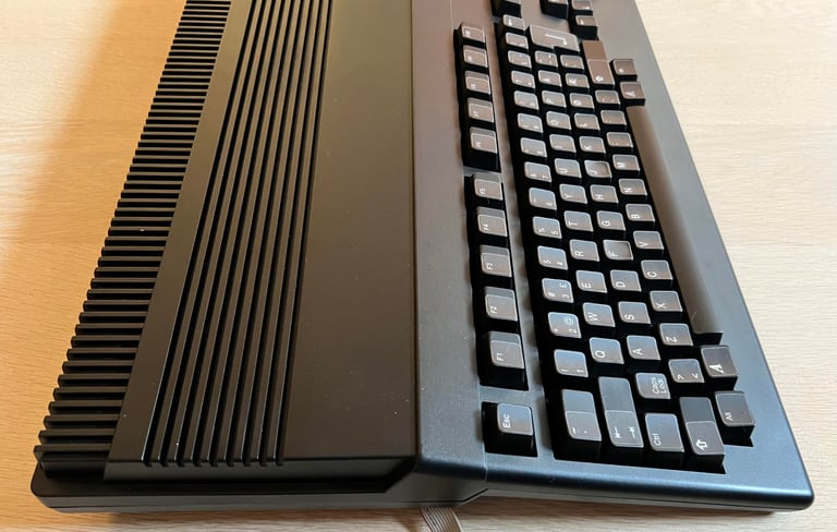
Below is a collection of the final result from the refurbishment of this Amiga 500. Hope you like it! Click to enlarge!






Banner picture credits: Ajne01
