
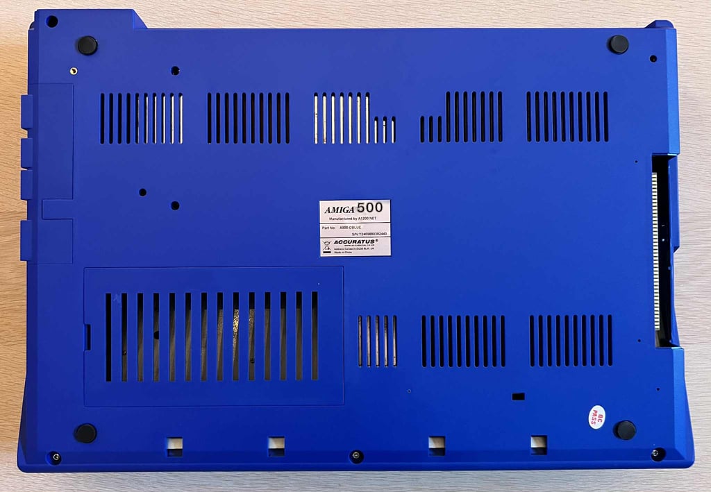
Amiga 500
Ser. No. Y2409880382440
Assy 312510
Artwork 312513 REV 6A
Starting point
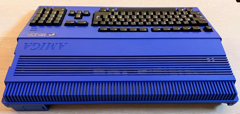
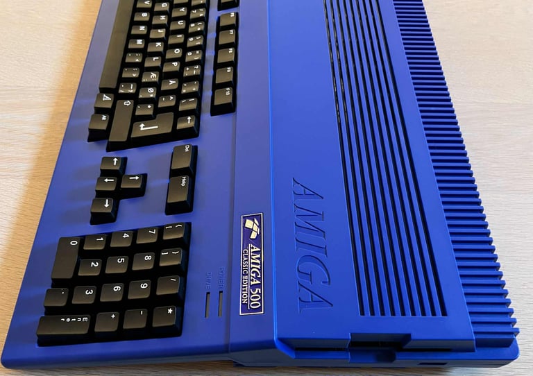
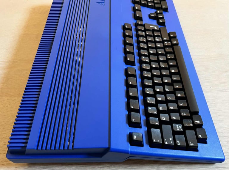
This cool looking blue Amiga 500 is in for some refurbish! It is very nice to see that modern replacements such as new black keycaps and blue covers can lift the retro Amiga to new levels! The original machine has probably lived a quite hard life. The story what happened to it, before new covers and keycaps were installed, are unknown. Nevertheless, there are some issues which needs some attention reported by the current owner:
The machine is partly working. Sometimes the machine doesn´t boot up.
There has been some unknown liquid exposed to the mainboard and socket(s).
Some of the keys are not responding as they should, and some of the large keys are missing the support stem.
The original floppy drive did not work.
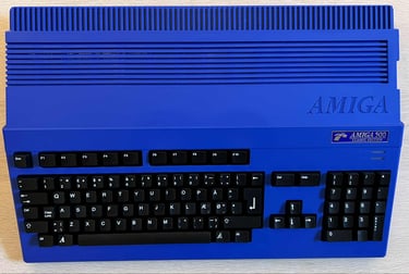
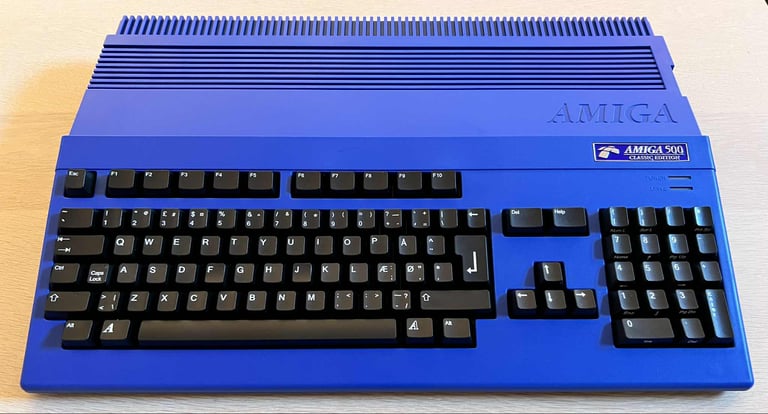
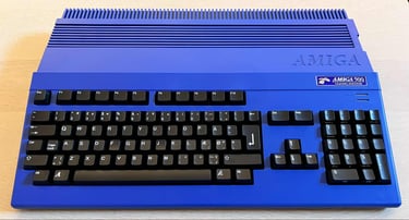
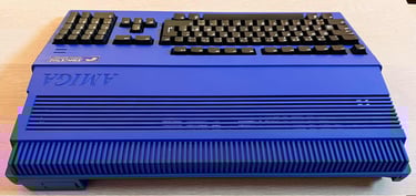
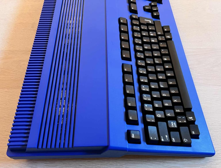
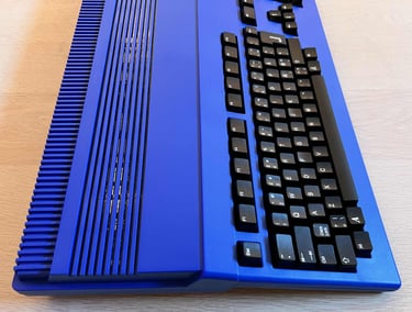
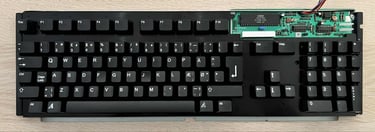
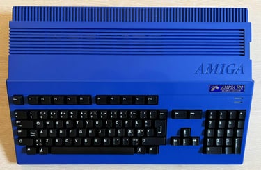
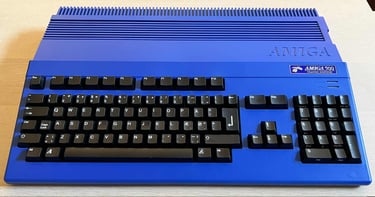
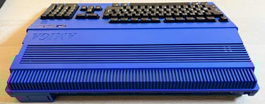
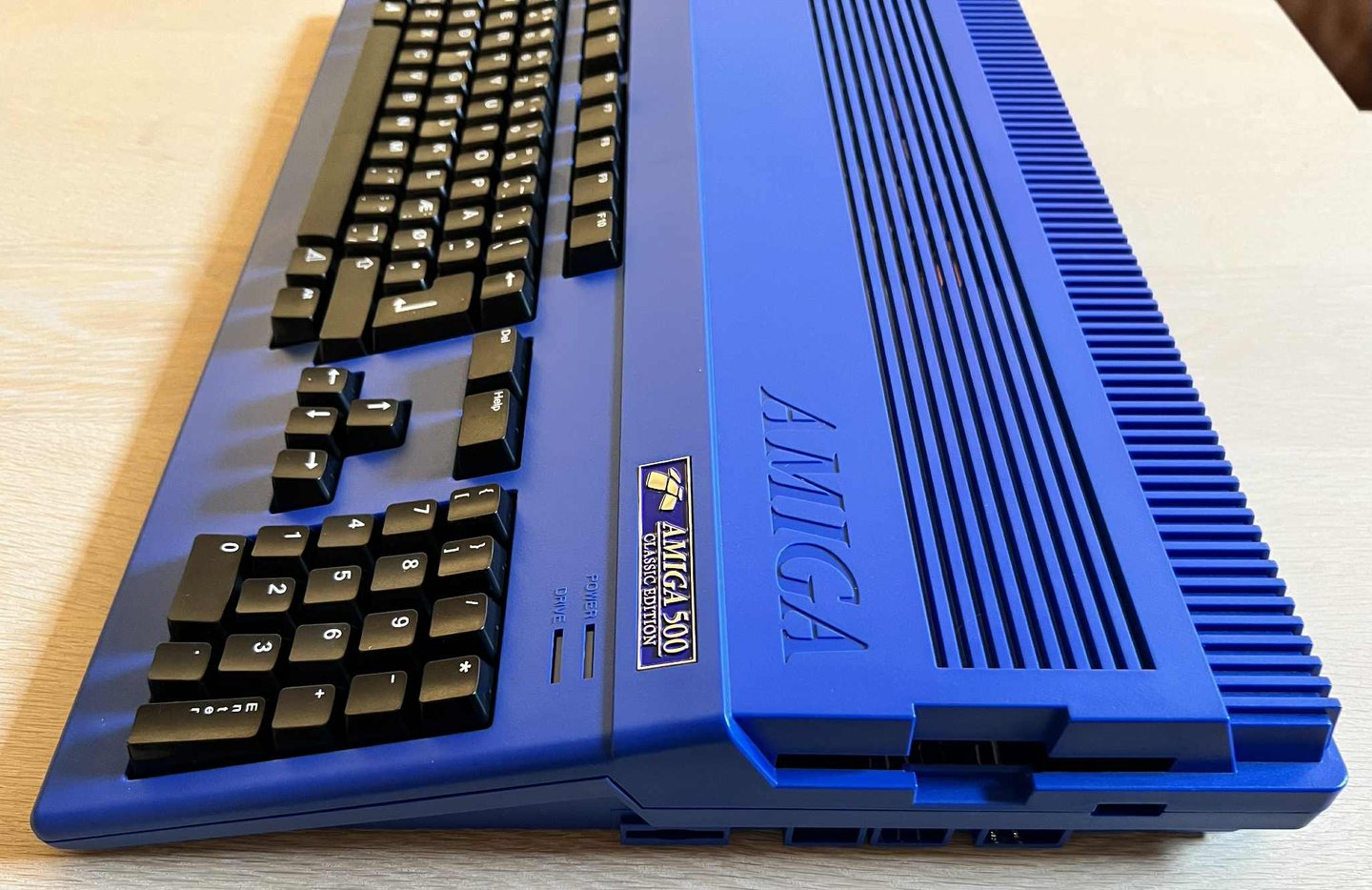
Below are some pictures of the blue Amiga 500. As expected the exterior casing (labeled "Amiga 500 classic edition") looks absolutely beautiful, and the brand new black keycaps matches the Amiga perfectly. The left hand side expansion cover is missing, and the original floppy drive is not installed (but supplied by the owner separately).


Refurbishment plan
To refurbish this Amiga 500 the plan is to do this trough the following steps (some of them in parallell):
- Check and restore the keyboard
- Refurbish the main board
- Refurbish and install floppy drive (postponed)
- Verify operation by testing
Disassembly
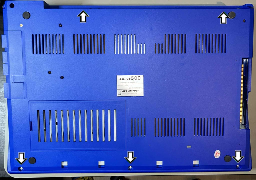
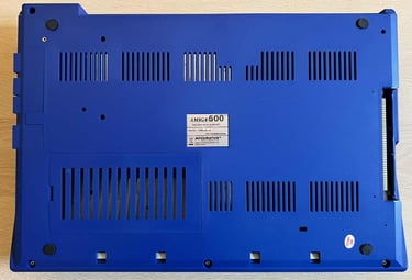
What I really like with modern Amiga covers is that they use proper machine screws to hold the top- and bottom cover together. There are five 3 x 8 mm PH2 machine screws at the underside of the machine which must be removed for disassembly.

With the five screws out of the way, the top cover is lifted. Now most of the RF-shield is exposed, and it is obvious that there have been some leakage entering the machine. The left hand side of the RF-shield is heavily corroded.
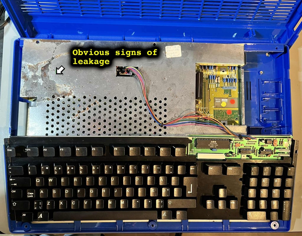
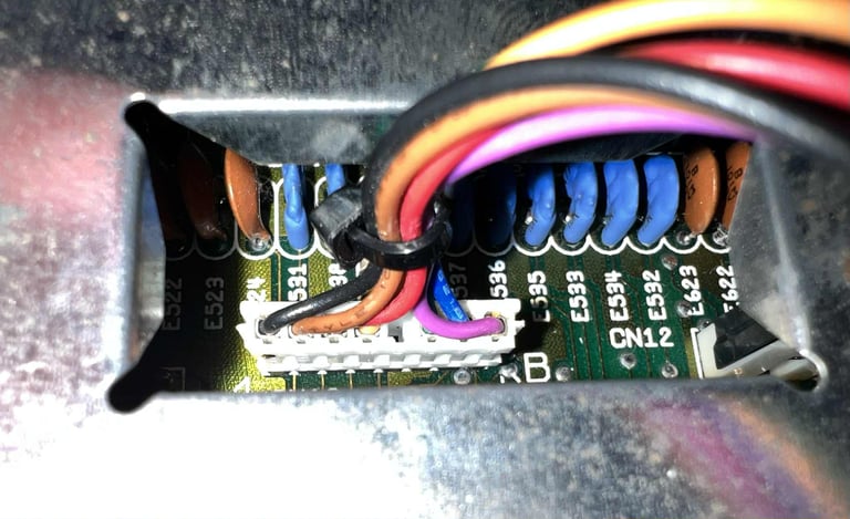
The keyboard connector is carefully pulled away from the mainboard. Note the orientation of this connector: black wire to the far left. Since the connector is not keyed it can be installed the wrong way when re-assembled later.

Now the rest of the RF-shield is exposed. And luckily, the leakage is limited to the top left hand side. There are no signs of leakage in the lower areas.

To start removing the RF-shield the four small metal tabs needs to be bent to a straight angle (see arrows in picture above). One of these tabs are missing. This is very normal as these metal tabs will only survive a few straightenings before they break. But this is not a problem. The RF shield will be held sufficiently by the remaining tabs and screws.
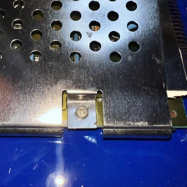
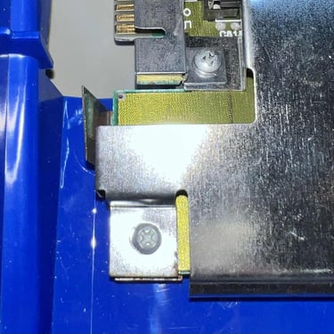
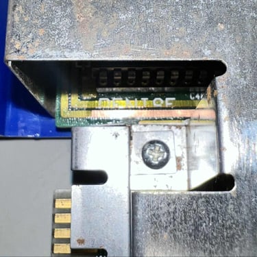
I notice that there is a missing screw on the top of the left side expansion port, and that another screw is of a wrong size. Not a big problem, but I will fix this later during re-assembly.
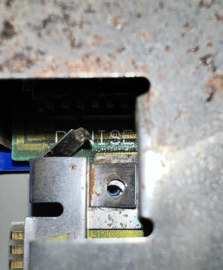

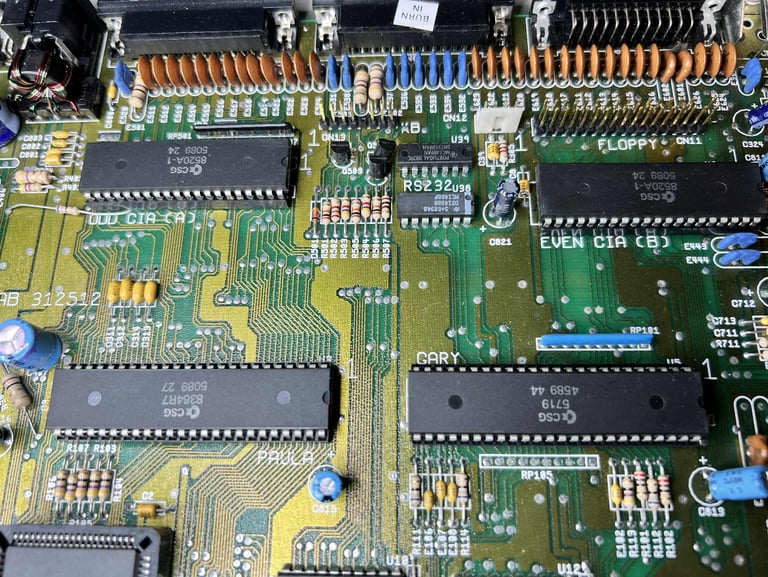
Now the RF-shield can be lifted off and the whole mainboard is exposed. I can immediately see the damage done by the leakage: from the left side around Denise, then moving in the "canal" between the two CIAs and Gary/Paula ending up in the reset circuitry.

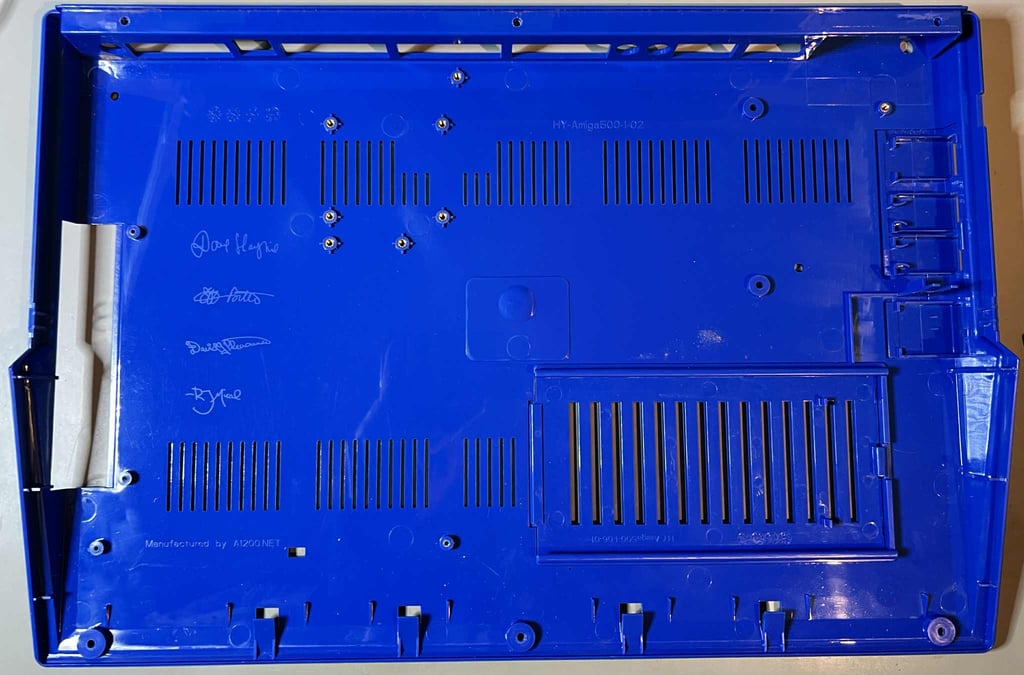
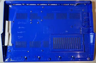
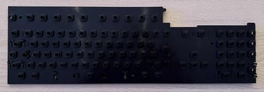
The mainboard can now be lifted off the bottom cover (some small amount of wiggling is required), and the bottom cover is revealed in all its glory. And this is so cool! In the bottom cover the names of the designers (I guess) of the new covers are etched in! Nice!
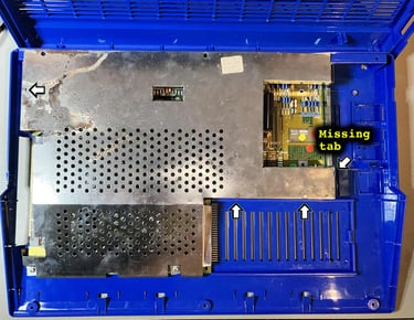
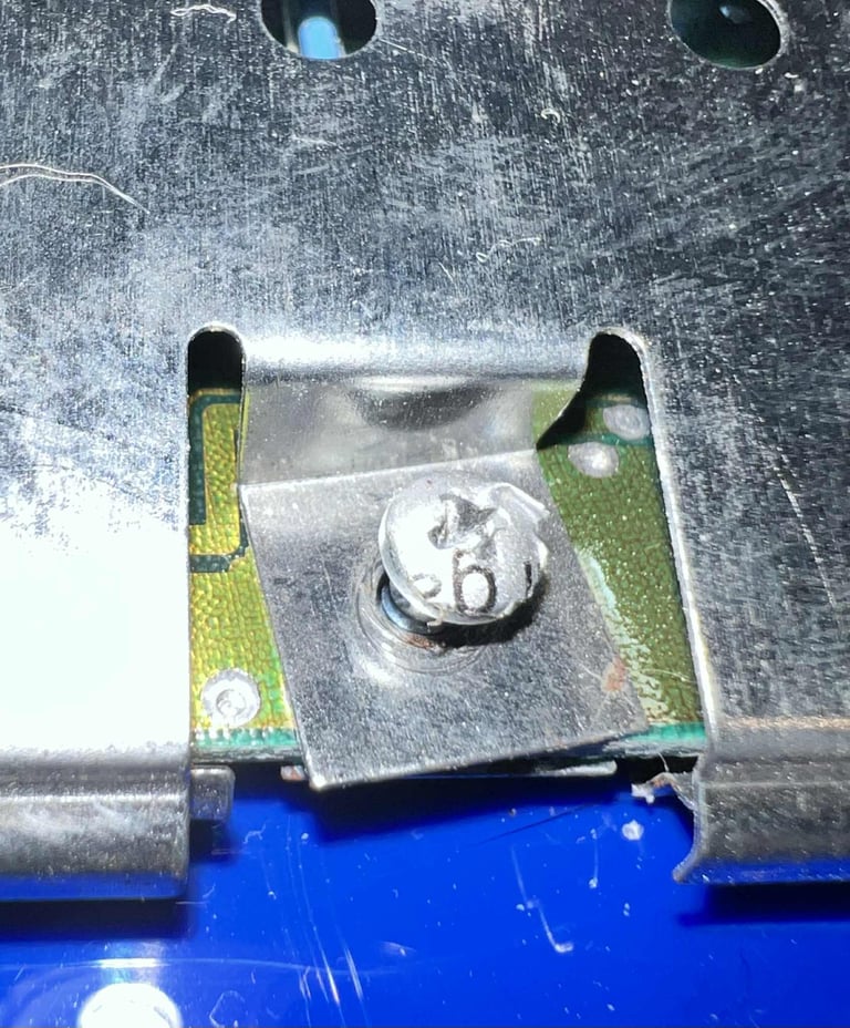
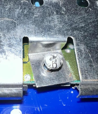
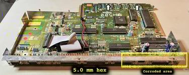
Before the mainboard can be lifted from the bottom RF-shield, the twelve 5.0 mm hext nuts must be removed. Also, there are two small clips near the RAM area (see arrows in the picture below) which must be carefully bent away. I notice that there are some significant corrosion/rust on the RF-shield near the RGB- and composite video connectors.

With the hex screws out of the way, the mainboard is lifted from the bottom RF-shield. And now there is another surprise: there are obvious signs of moisture on the right hand side of the RF-shield. This is the area where the floppy drive is located. But I can not see any signs of liquid from the top side of the mainboard in this area? Strange...
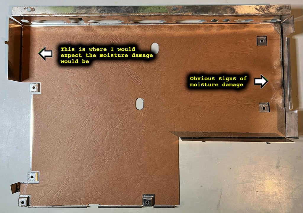
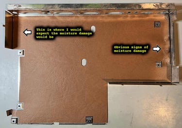
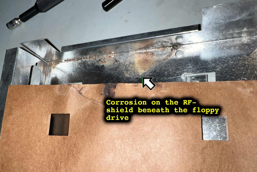
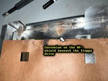
Beneath the cardboard shield there are some corrosion/rust from the moisture damage. No surprise there.
Keyboard
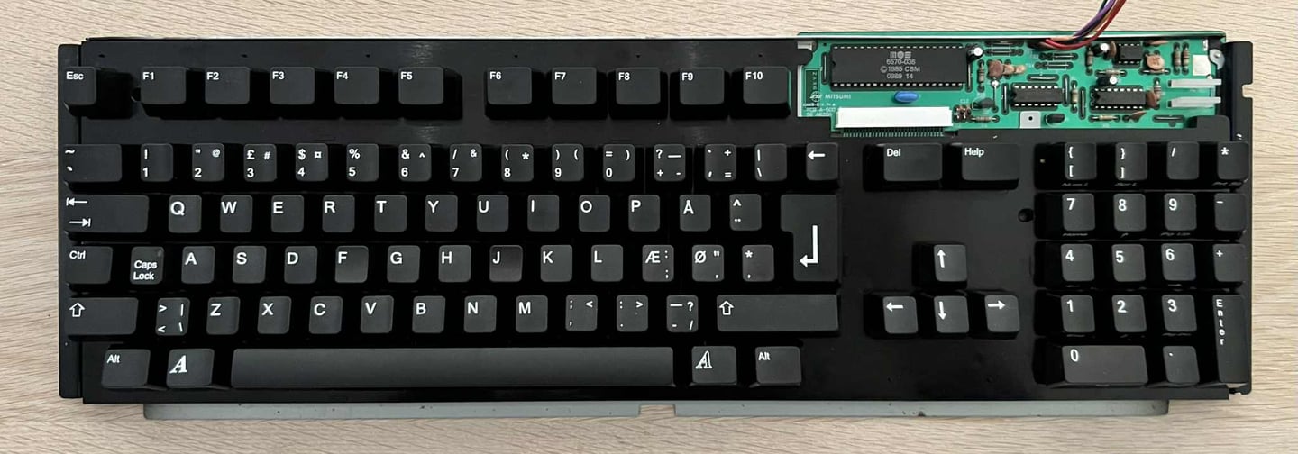
Amiga 500 keyboard with black keycaps? That is really awesome! It looks really cool together with the blue covers. Nevertheless, there are some issues reported with this keyboard:
Some of the keys are known to not work (or respond)
Some of the larger keycaps are not properly attached
Visual inspection
Yes, it looks great, but there are some things I notice with the keyboard which needs attention in addition to the issues mentioned aboved:
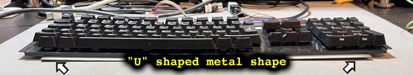
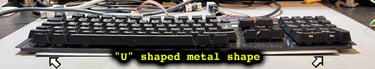
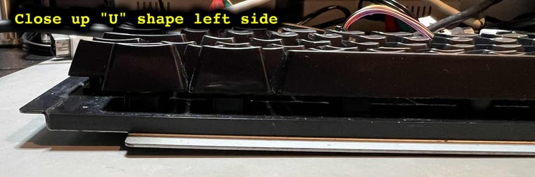
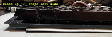
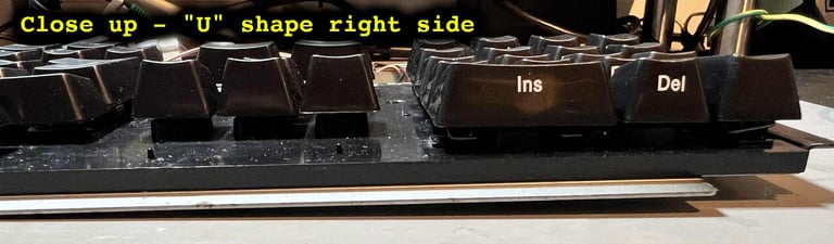
The keyboard is bent in a "U" shape fashion. This is something I have seen in other Amigas as well, but I am not sure what causes this.
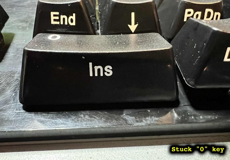
The "0" key in the keypad section gets stuck when pressed down


Attaching the larger keycaps
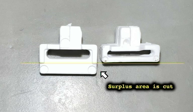
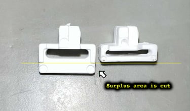
Some of the larger keycaps are not properly attached. This is not a big problem, as they will work, but it is nice to attach them properly. The reason why they are not properly attached is that the plastic stems following the keycaps are a bit too long. As a consequence the keycaps will not travel the whole way. To fix this the stems are cut to the correct size. There are two sizes of the keycaps stems, and the long ones will not work for keycaps such as "TAB", "0", "Enter" etc.
Checking the keyboard
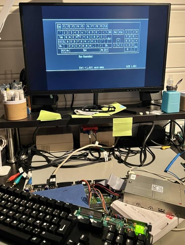
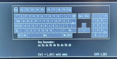
The keyboard is reported to be only partly working. To test this the keyboard is tested using the Amiga Test Kit software running from spare (partly working) floppy drive. NOTE: The picture quality, and colours, are completely off. But this is not due to the Amiga itself, but my test setup which is not capable of displaying the picture as it really is.
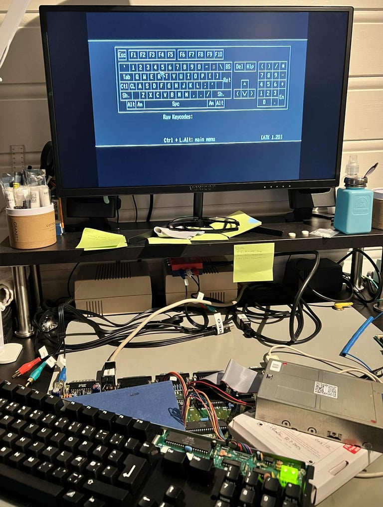
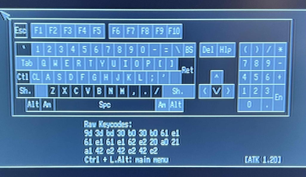
As can be seen from the picture below several of the keys are not responding to key presses. All the keys which are "blank" in the picture, such as ESC, RETURN and SPACE is not working. What could cause this problem? My guess is that this is due to a faulty membrane. These old membranes are notorious for failing, and since we know that there have been liquid damage to the mainboard, I would not be very surprised if there are some liquid damage on the membrane as well. And since these membrane are so fragile, even the slightest accumulation of dust and moist could cause one or several of the traces to disintegrate.

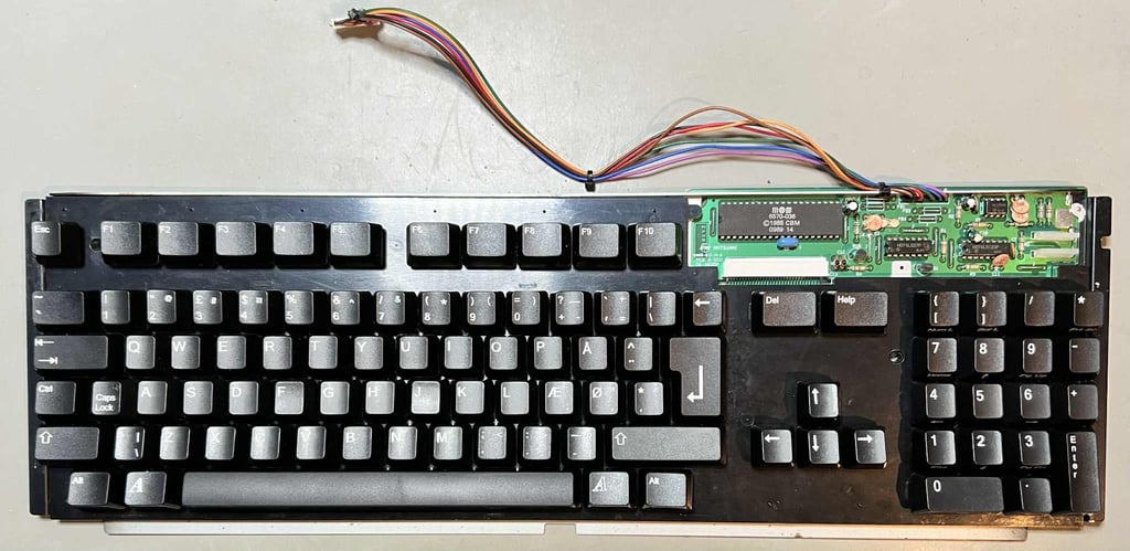
Disassembling the keyboard
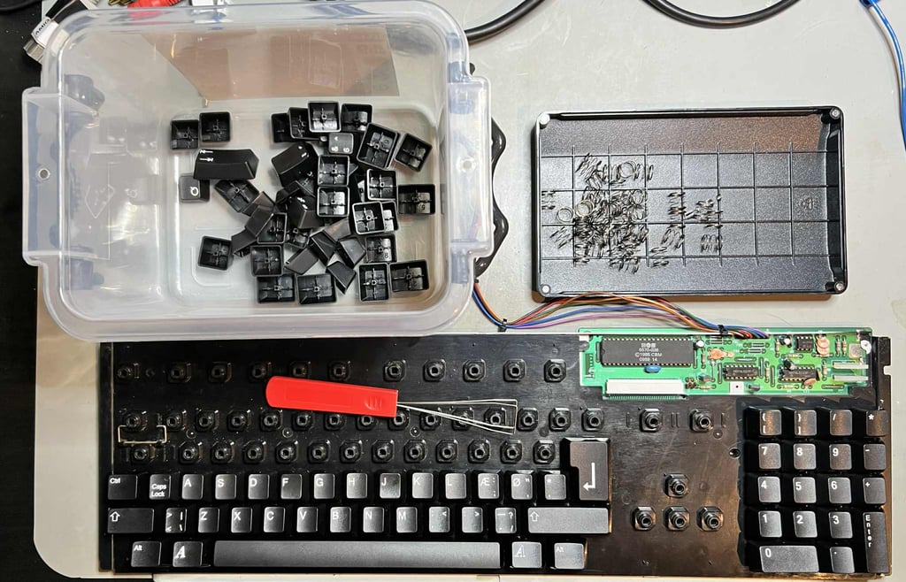
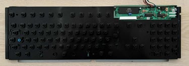
First action is to remove all the keycaps. There are very easy to remove since the keycaps are not original, and can be removed by using fingers only. But to speed up the process a keycap puller is used. Note that beneath the spacebar there are in addition to the centre spring also two small springs on each side.
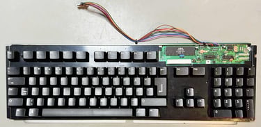
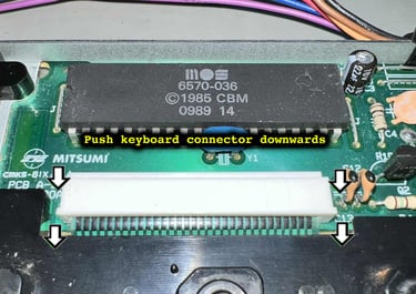
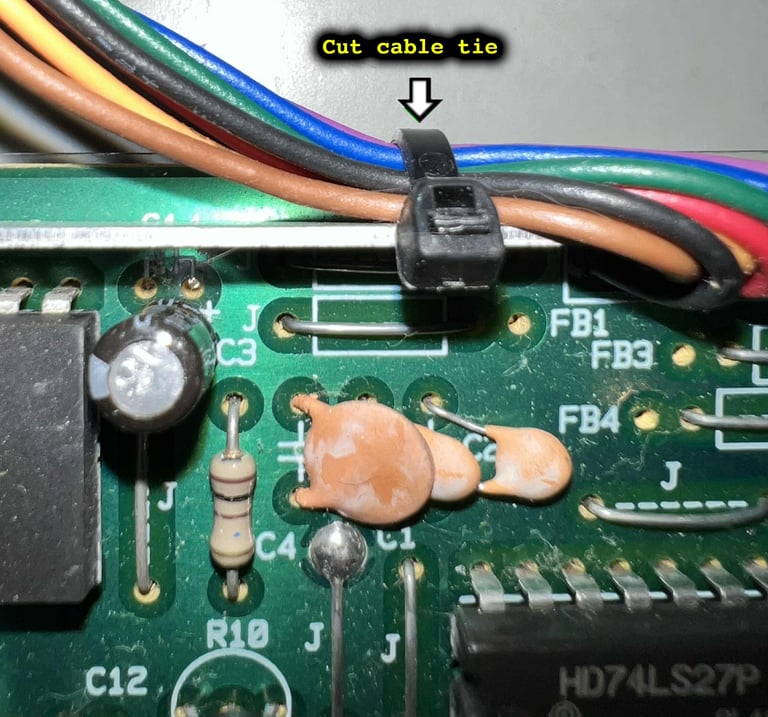
Next, the keyboard connector is pushed downwards on each side. You can use a small flat screwdriver (or some other small tool) for this purpose. When the connector is pushed downwards the keyboard membrane is now "free", but it can´t be released until the PCB is also removed. Starting to remove the PCB the small cable tie is cut


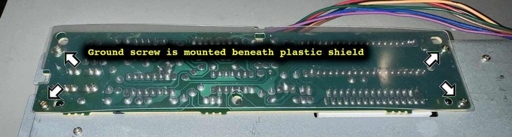
There are four screws holding the PCB to the bottom metal frame which are removed. Note that one of the screws, the ground screw, is actually mounted beneath the plastic insulating shield. This is normal and the way it should be to make proper contact. With the screws out of the way the PCB can be carefully removed from the keyboard.
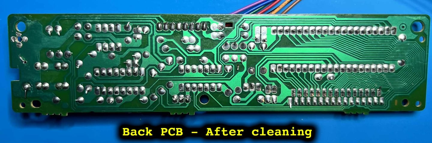
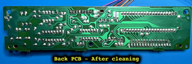
Checking and cleaning the keyboard PCB
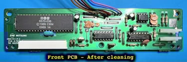
This is a standard Mitsumi A-500 56 A620A PCB used in A500 machines. It is a bit dirty, but otherwise it seems to be in good condition, but there are two things I notice:
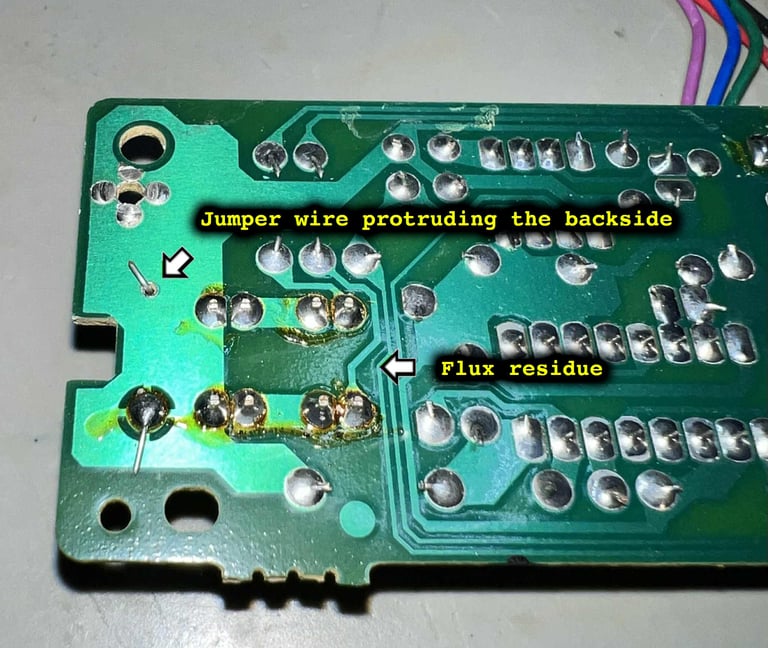
There are some flux residue after the LEDs and jumpers were soldered in (manually at production line)
The jumper wire is protruding to the backside of the PCB. This is normally cut short since it is soldered at the front side of the PCB.
None of these are critical, but the flux is removed by cleaning the whole PCB with isopropanol. The protruding jumper wire is left as it is - for authenticity.


Checking the keyboard membrane
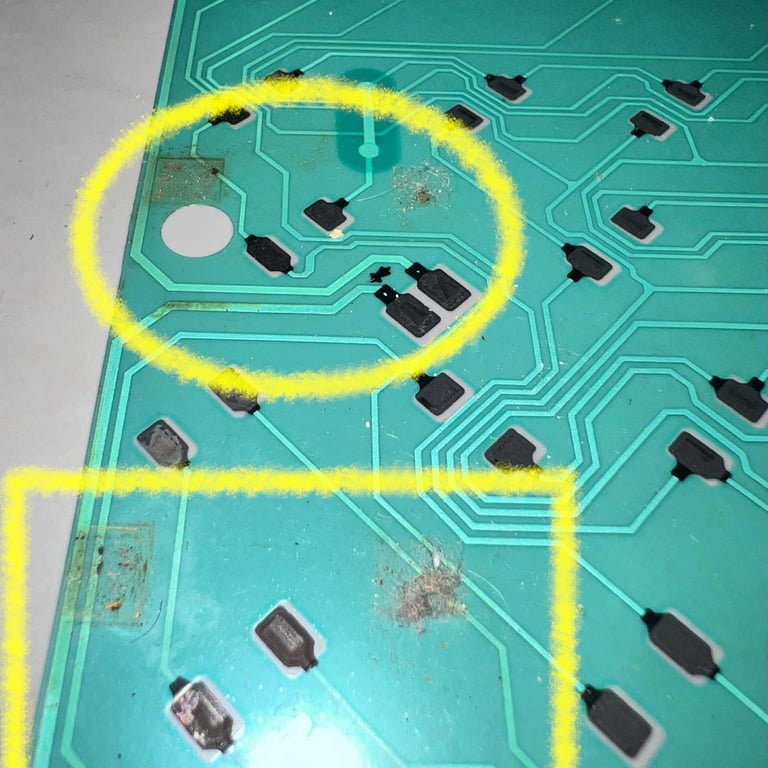
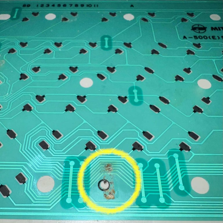
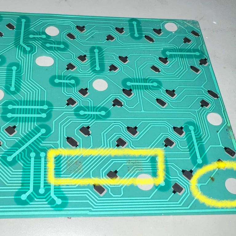
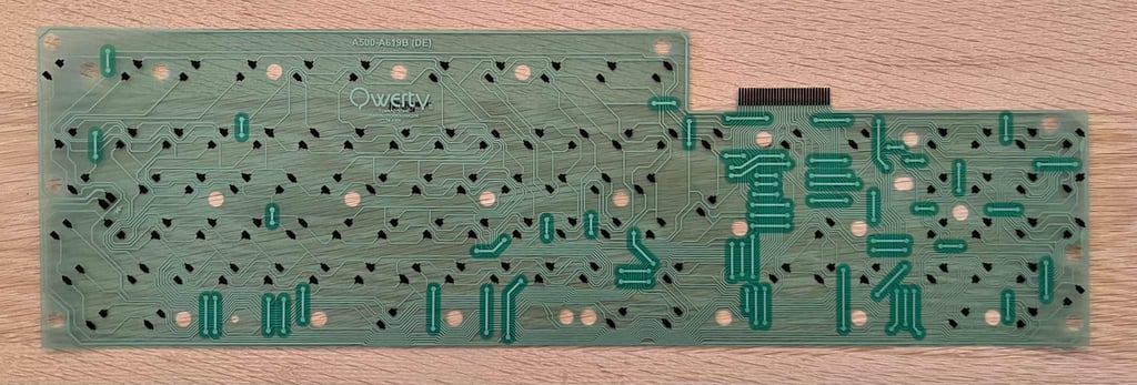
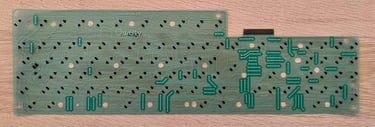
The keyboard membrane is a Mitsumi A-500(E)56 A619B. And I can immediately see trouble ahead. There are several areas covered with grease and dust. The Mitsumi keyboard membrane is notorious for failing due to moist accruing and corroding the tracks.
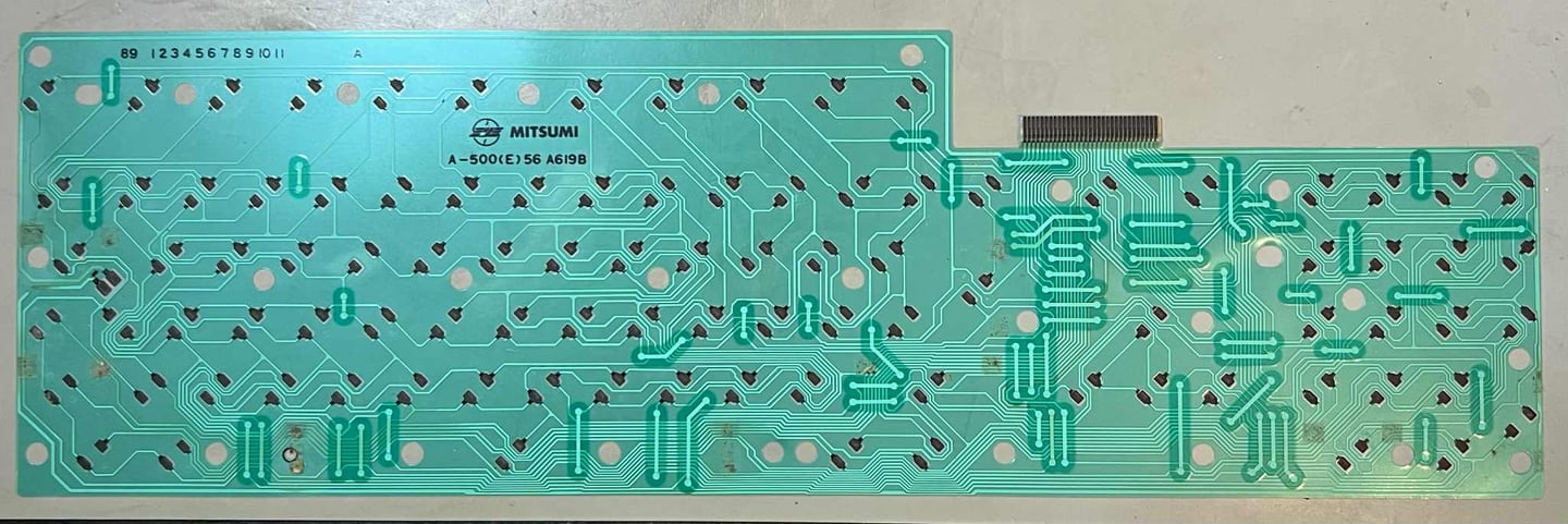
With a multimeter in "beep-mode" the traces running beneath the grease spots are checked. And I find several traces which are broken. So this membrane is no longer working unfortunately. Below are some close-up pictures of the grease and areas of broken traces (click to enlarge).
Repairing broken Mitsumi is not worth the effort from my point of view. The membrane is so fragile, and even if you manage to fix a trace, chances are high that another trace will disintegrate just a few months later. Instead, a brand new membrane is ordered from Amigastore.eu.
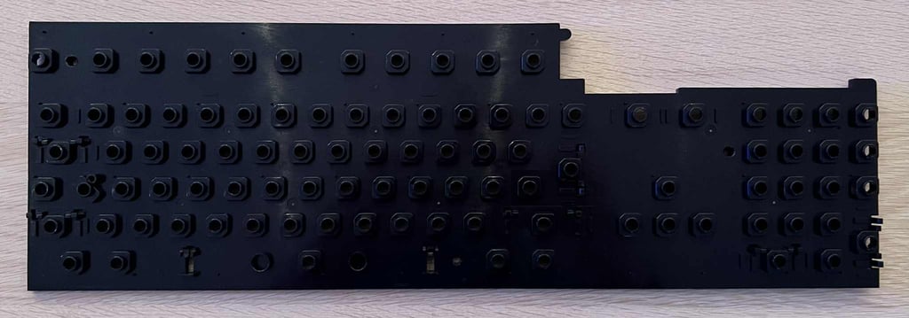
The plastic frame was not very dirty, but it was cleaned nonetheless.
Straightens the metal frame
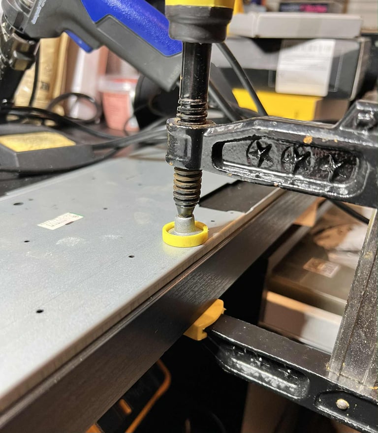
As previously mentioned the metal frame holding the keyboard is "U" shaped. An attempt to fix this, or at least reduce the deformation, the metal frame is clamped to the desk for about two weeks. Hopefully this will slowly remove the deformation - make the metal frame level to the desk.

The metal frame is not 100 % straight after this process, but it is way, way, better! With the "new" metal frame in place and the new membrane the plungers and PCB is assembled together with the rest.

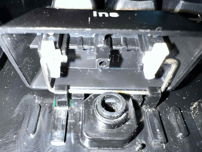
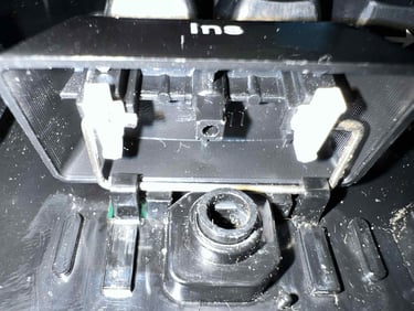
All the keycaps are put back on the keyboard. Two of the keycaps, the SPACEBAR and the "KEYPAD 0", require a bit of customisation. The small white tabs inside the keycaps are filed a bit to make sure the key can move freely.
Removing rust
Due to the liquid that has been spilled on this Amiga once upon a time, there are some corrosion on both the top- and bottom RF-shield. The way to remove the corrosion is:
Soaking the rusted area with vinegar (and cotton buds to really massage the vinegar into the rust)
Using scraping tools such as screwdrivers and metal files to remove the rust
Repeat again, again, again and again
Clean everything with plenty of soap and clean water
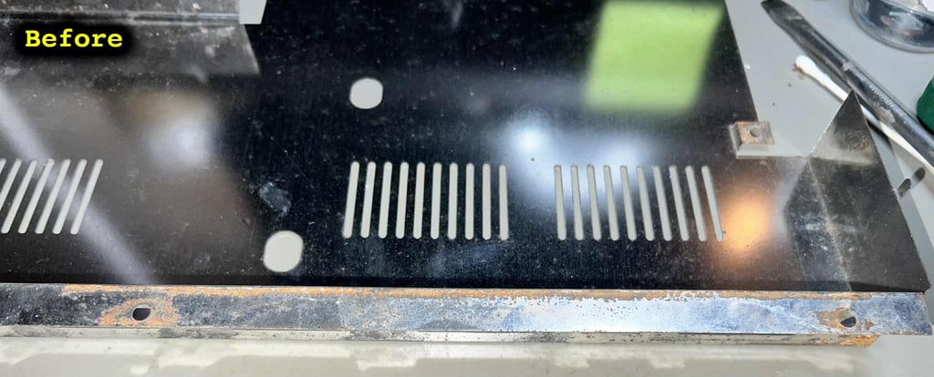
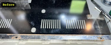
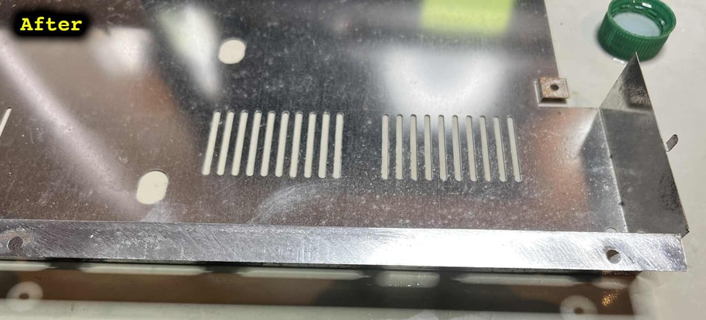
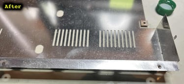
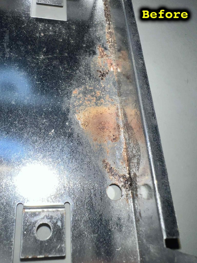
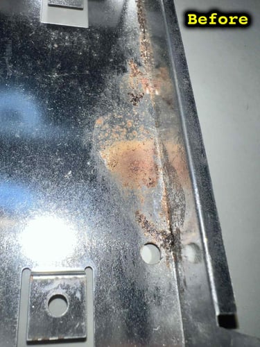
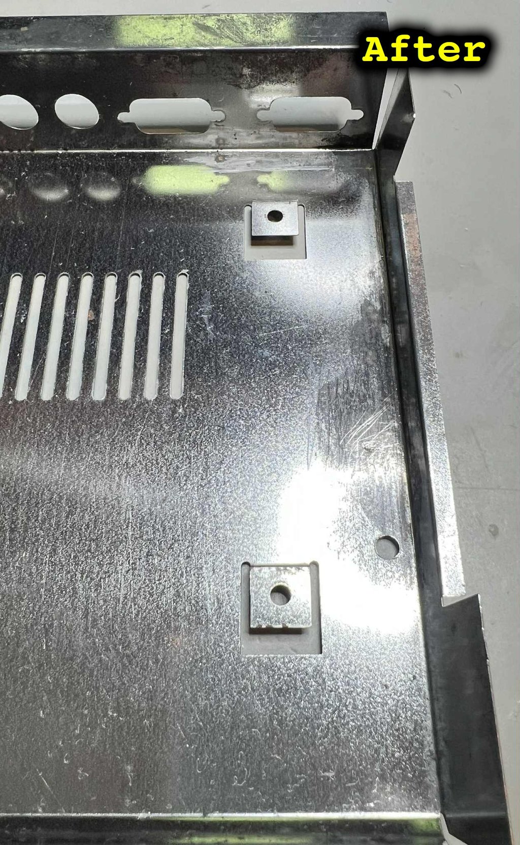
Top RF-Shield
Below are some pictures of the top RF-shield before and after the refurbish.

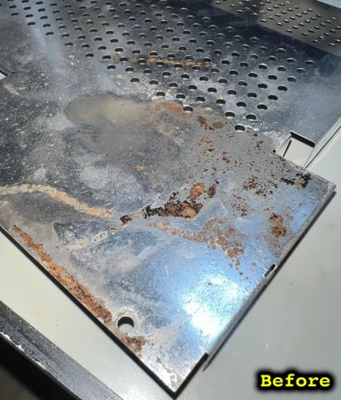
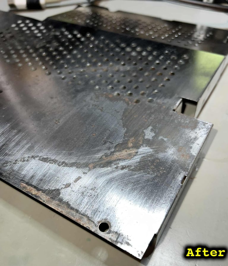
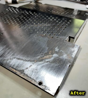
Bottom RF-shield
Below are some pictures of the bottom RF-shield before and after the refurbish.

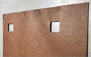
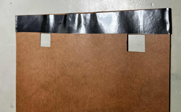
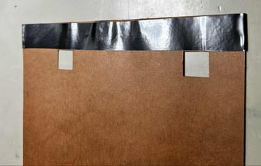
As a precaution, the moist area on the cardboard is covered with some insulation tape. The moist is probably long gone, but just to make sure that no moist is touching the metal some tape would do the trick.

As previously mentioned there are som screws missing holding the PCB in place. So, new screws are inserted securing the mainboard to the bottom cover.
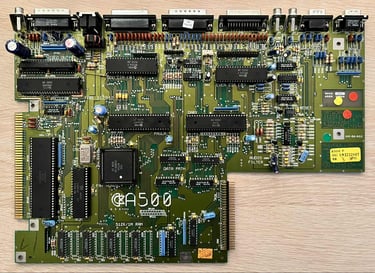
Mainboard
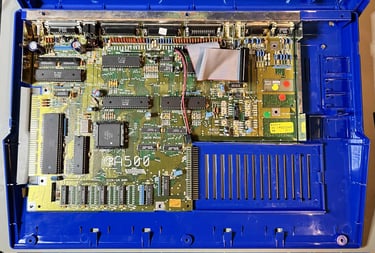
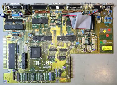
This mainboard is the Assy 312510/Artwork 312513 Rev 6A. Probably most known for the Fat Agnus (8372A) capable of addressing 1 MB of Chip RAM.

Visual inspection
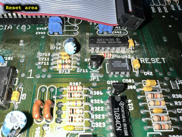
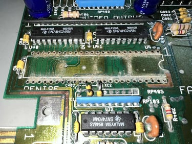
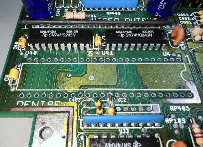
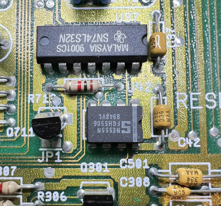
The key observation is: liquid damage. Some unknown liquid has entered the right hand side of the mainboard. The liquid has floated from the Denise area, through the canal between the two CIA´s and Paula/Gary and eventually ending up at the reset circuitry.

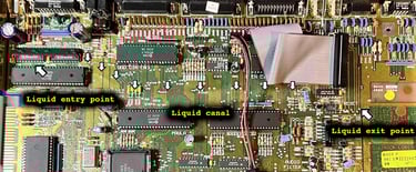
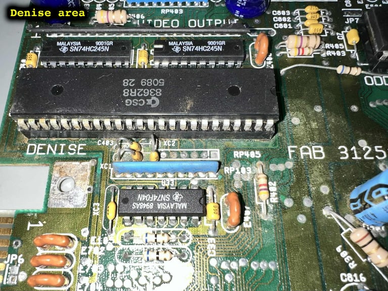
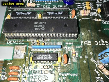
Below are some close-up pictures of the three areas. As can be seen from these pictures it is primarily the Denise chip/socket and the reset area which is most affected by the leakage.


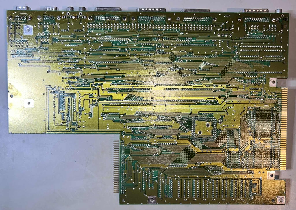
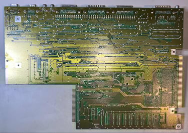
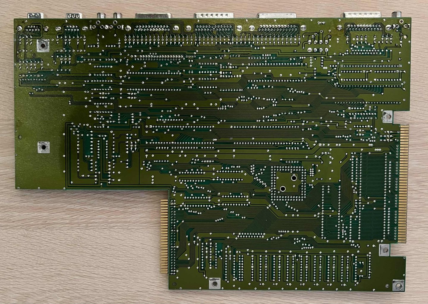
On the bright side I can not see any other obvious damage on the mainboard. No bulging or leaking capacitors, no broken connectors or signs of broken traces. Also, the backside of the mainboard looks in good condition. And this kind of surprises me. I was actually expecting some signs of corrosion, but I can not find anything.
All the custom ICs are listed in the table below. It is fair to say that this machine was produced somewhere late in 1989 and beginning of 1990. This was also a time of great importance in Europe. At the very same time the wall in Berlin fell, and the unification of West- and East Germany began. So this machine is born at the very same time of this important era of European history!
Initial testing
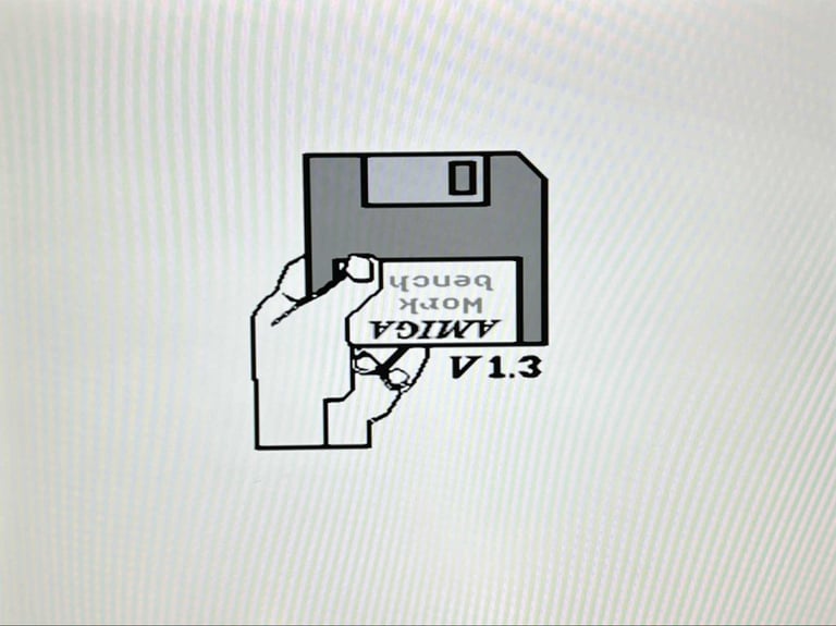
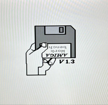
I am a bit hesitant to power the machine, but since I know that it has been powered recently I take the chance. And the machine boots to normal "Insert disk" screen on first attempt! I am actually quite amazed considering the amount of corrosion.
NOTE: There are NO colours on the picture. This is because my video capture device is not capable of recognizing the colours, but it is expected to be a problem on the capture and not on the Amiga.
Checking the voltages
Even if the machine powers on without any issues it is good practice to measure the voltages - to verify that all voltages are present and within tolerances. Voltages which are not within acceptable tolerances are often a symptom of faults (just like a doctor would check temperature and blood samples).
As the table below show all voltages are present and ok. Note that this table will be updated after completing the refurbish.
Handling corrosion
The most serious issue with this Amiga 500 is the corrosion in the three areas described earlier. First, the area around the 8362 Denise IC is cleaned with vinegar. Since the vinegar is a liquid it will penetrate the area nicely beneath all components. After a couple of minutes the area is cleaned properly with isopropanol to remove the vinegar residue. This process is repeated several times.
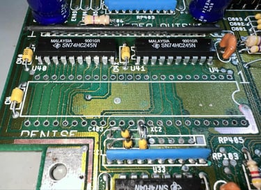
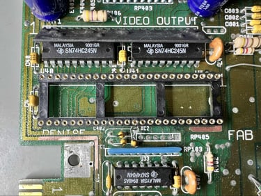
The socket holding the Denis is very corroded itself so the socket is desoldered from the mainboard. As can be seen from the picture below the corrosion is severe beneath the socket.
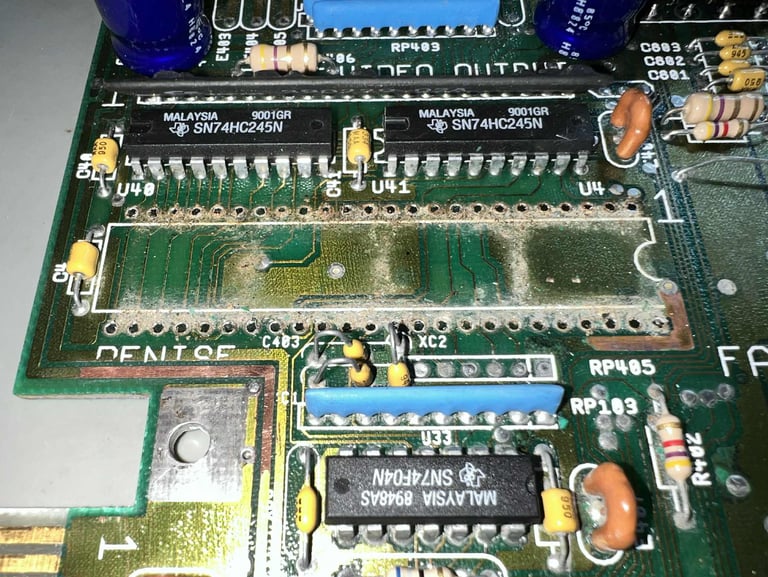
The corrosion beneath the Denise socket is also cleaned with vinegar, isopropanol and glass fibre pen. The picture below shows the result of the cleaning.
A new machine pin socket (48 positions) is soldered to the mainboard.

NOTE:
The 8362 Denise chip is properly cleaned with isopropanol and glass fibre pen before it is re-inserted into the socket
Some of the PCB mask were removed during the operation which exposes the copper. These areas are covered with some transparent nail polish.
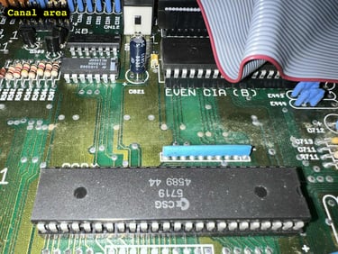
The reset area, and the "canal" area, is also cleaned properly with a combination of vinegar and isopropanol. This is a tedious job, but the end result looks quite good. See pictures below.

Below are some pictures of the mainboard after refurbish. This is to me a fine looking Rev 6A board!

Testing
SPOILER ALERT! The machine fails to boot when the keyboard is installed!
Ah... the typical joy of repairing old Commodore equipment. Everything is ready for final assembly, and then.... nope.... doesn´t work. Hehe! Oh... joy! Well, this is the life of refurbishment!
So, what happens? Well, the machine does seem to work when the keyboard is not connected. It boots up fine, and can read software from a floppy drive. But the moment the keyboard is installed the machine starts to go into a reset-looking loop. Se video below (Note: Ignore the weird looking colours on the screen. This is only due to my poor video converter).

Troubleshooting
First step in the troubleshooting is to try the machine with a known-working keyboard. This should give an indication if the fault(s) is on the Amiga mainboard side or the keyboard side.
Result: The fault is still the same even when a known-working keyboard is attached. So the problem is most likely on the mainboard.
Next step is to do a visual inspection of the mainboard of three areas:
The Denise area. In this area a new socket is installed and a lot of old leakage is removed.
The "canal" area. This is the area between the CIA#1/2 and Gary/Paula are located. A lot of old leakage is removed here.
The reset area. This is the area surrounding the reset circuitry. A lot of old leakage is removed here.
It is not unlikely that a trace is broken during this repair and cleaning in these areas. When doing these kind of cleaning and refurbish you will often provoke faults (which would appear later anyhow).
Result: I can not see any obvious reason after visual inspection. Also, quite some traces were tested with a multimeter, but nothing was showing up as a bad trace.
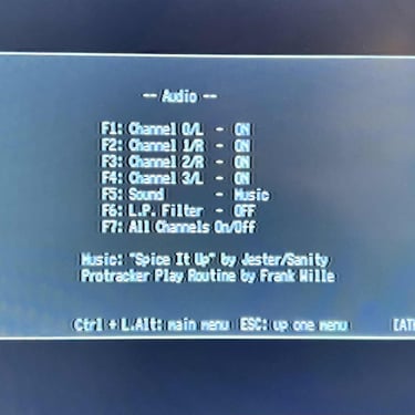
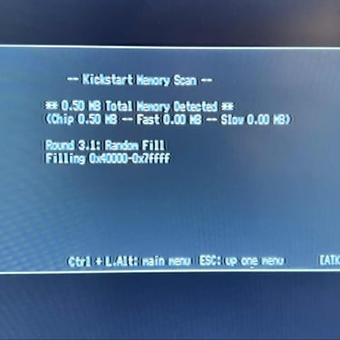
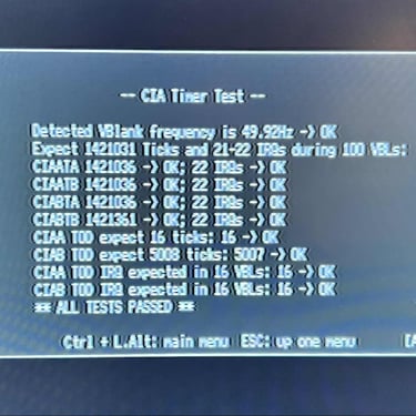
Since the machine seems to be otherwise working the Amiga Test Kit is runned. This is to see if any other faults than the keyboard appear which could lead to a hint.
Result: All tests seems to pass fine. The Amiga Test Kit did not give any indication on any faults. See table below for details.
My hypothesis is that the fault is caused by communication issues between the keyboard and the mainboard. The keyboard is connected to an eight pin connector (CN13) to the mainboard. Only seven of these are used for communication and power (the key pin is not used). See schematics below.
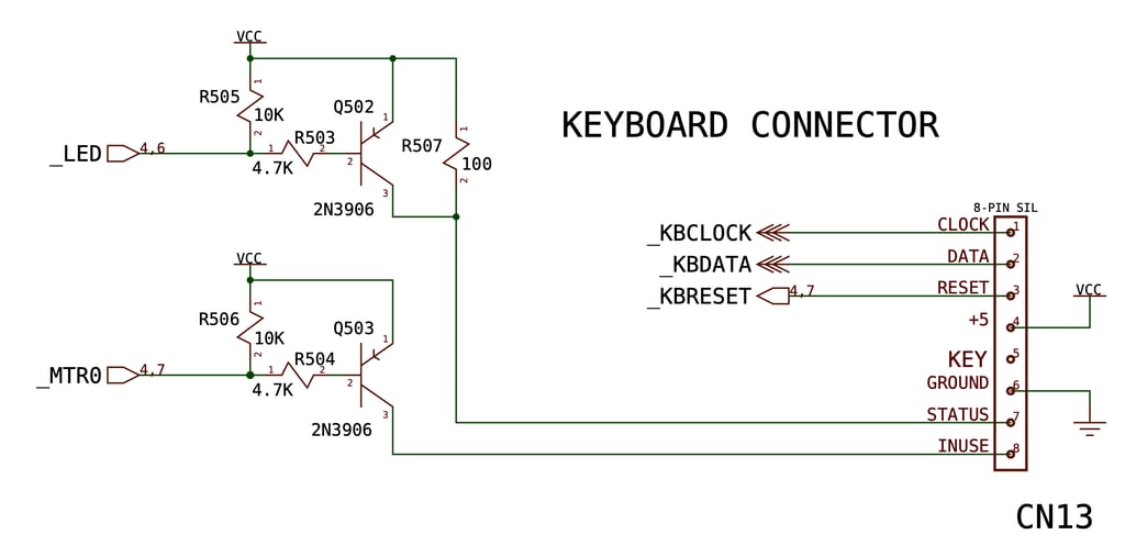
From the Amiga Hardware Reference manual the _KBCLOCK and _KBDATA should be set HIGH (+5 VDC) at the mainboard before the keyboard starts the transmission by pulling the _KBCLOCK LOW. See picture below.

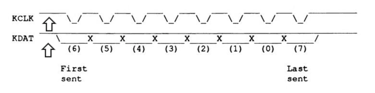
Checking the _KBCLOCK and _KBDATA something interesting is found. Both levels are indeed HIGH which is good, but the voltage levels are too high I think! They bare both 6.4 V. The same is for the pin 4, 7 and 8. This sounds like too much! Also, in the Amiga Hardware Reference manual the referred voltage should be +5 VDC.


Testing the machine with a different PSU (still an original Amiga PSU) the voltage levels at _KBCLOCK and _KBDATA drops to 5.1 V. Could this be the fault? A PSU with a too high voltage output?
Result: Success! When an alternative Amiga PSU is used the Amiga boots straight up to the boot screen with the keyboard installed! Nice!

Now that the machine is working (again) with the keyboard attached the new membrane is tested. Does all the keys work now? Yes. As can be seen from the picture below all keys are now working as they should.

The machine will be without a floppy drive for now. The original drive was too far off calibration, and requires significant adjustment which will be done at a later time. But the machine is tested with a temporary floppy drive. As can be seen from the pictures below all tests are OK. NOTE: The colours are completely off (!) This is due to a poor analog to HDMI converter. But the machine is also tested on a CRT and appears to be working as it should.
Final result
"A picture worth a thousand words"
Below is a collection of the final result from the refurbishment of this Amiga 500. Hope you like it! Click to enlarge!


Banner picture credits: Ajne01