

Amiga 600 [PAL]
Ser. No. 094095
FAB 315985-01
A/W 315988-01 REV 1.3
Starting point
This Amiga 600 came to be for a recap of the old electrolytic capacitors on the mainboard. And in fact, I did not plan to write an article about this quite straightforward operation, but it turned out to be a quite tricky operation! Note that the warranty seal is not broken - I am the first one here in over 30 years!
Recapping the A600 is mandatory. After 30+ years the SMD electrolytic capacitors will both have dried up and are likely to have leaked. This leakage can make severe damage to traces and components.
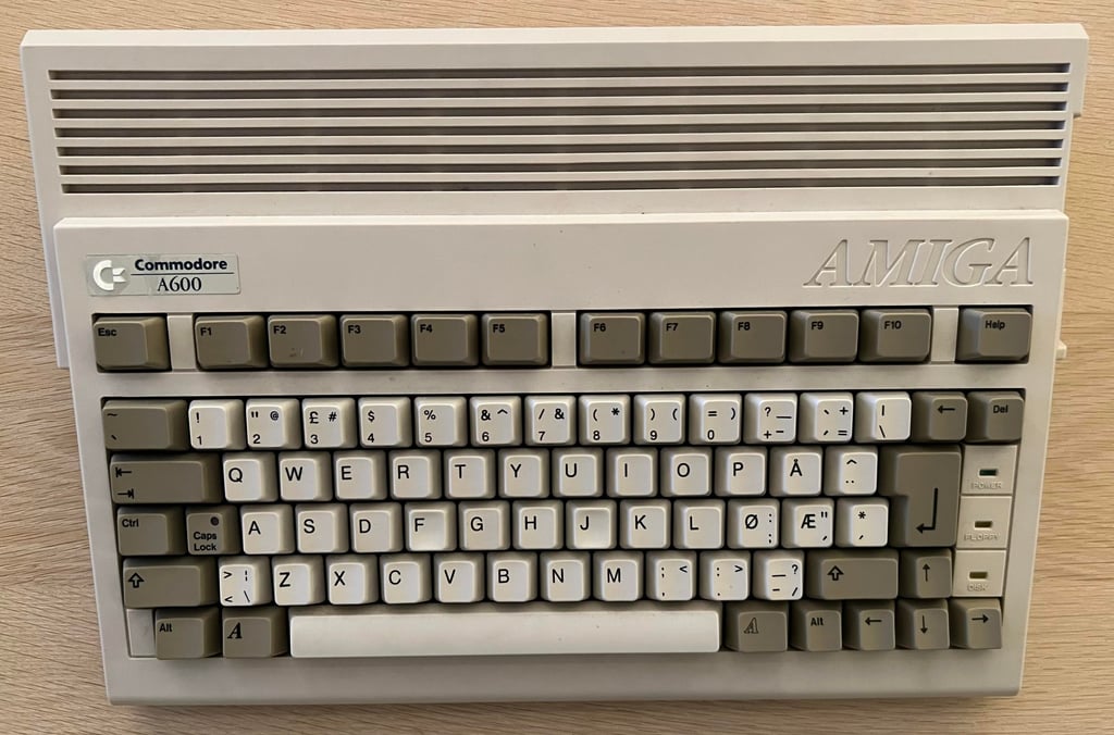
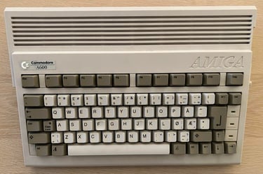
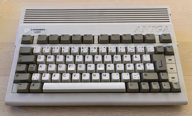
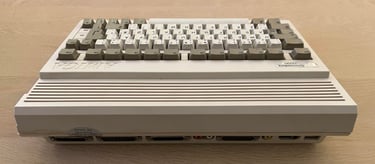
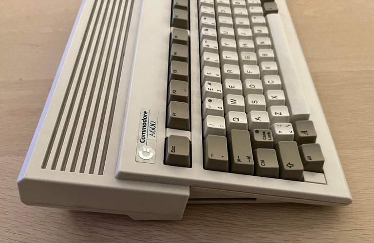
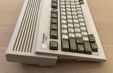
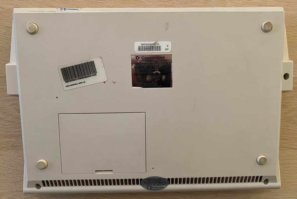
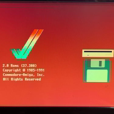
The Amiga looks very nice from the outside, and is in working condition. That is, I did not do a full test of it at arrival, but I did turn it on and the boot screen appears without any issues. Below are some pictures of the Amiga before recap.


Opens it up...
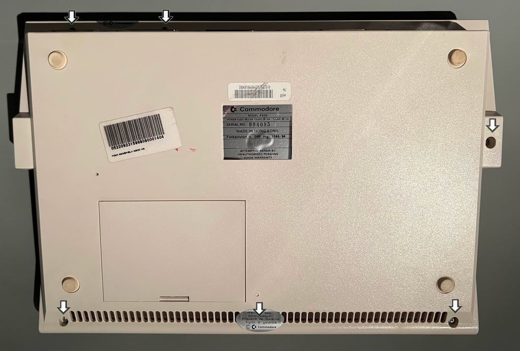
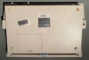
To open the Amiga 600 the six screws are removed. There are four larger screws at the front and right (underside) and two at smaller machine screws at the back. See picture below.
The top- and bottom cover is slightly separated by using opening tools from iFixit. With the top slightly lifted the keyboard LED connector is removed from the right side.

With the LED cable out of the way the top cover is lifted away. The inside is revealed, probably for the first time in over 30 years. It looks very good, some dust and grease but otherwise appears to be in very good condition.
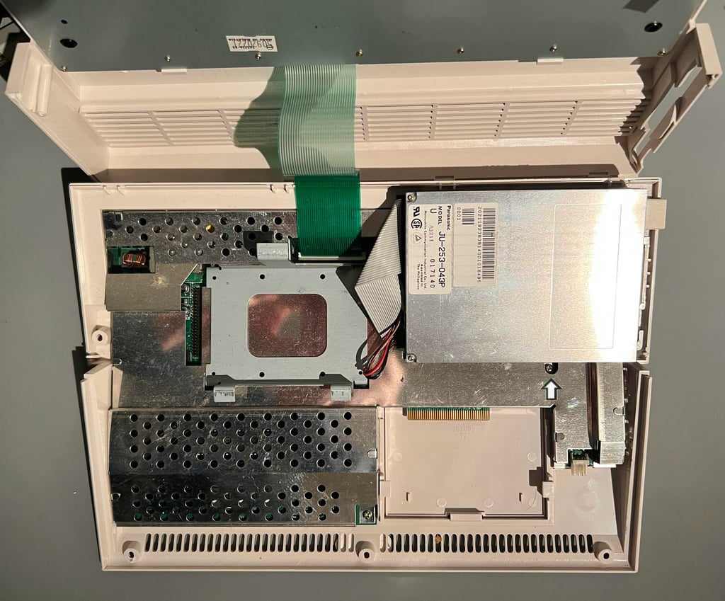
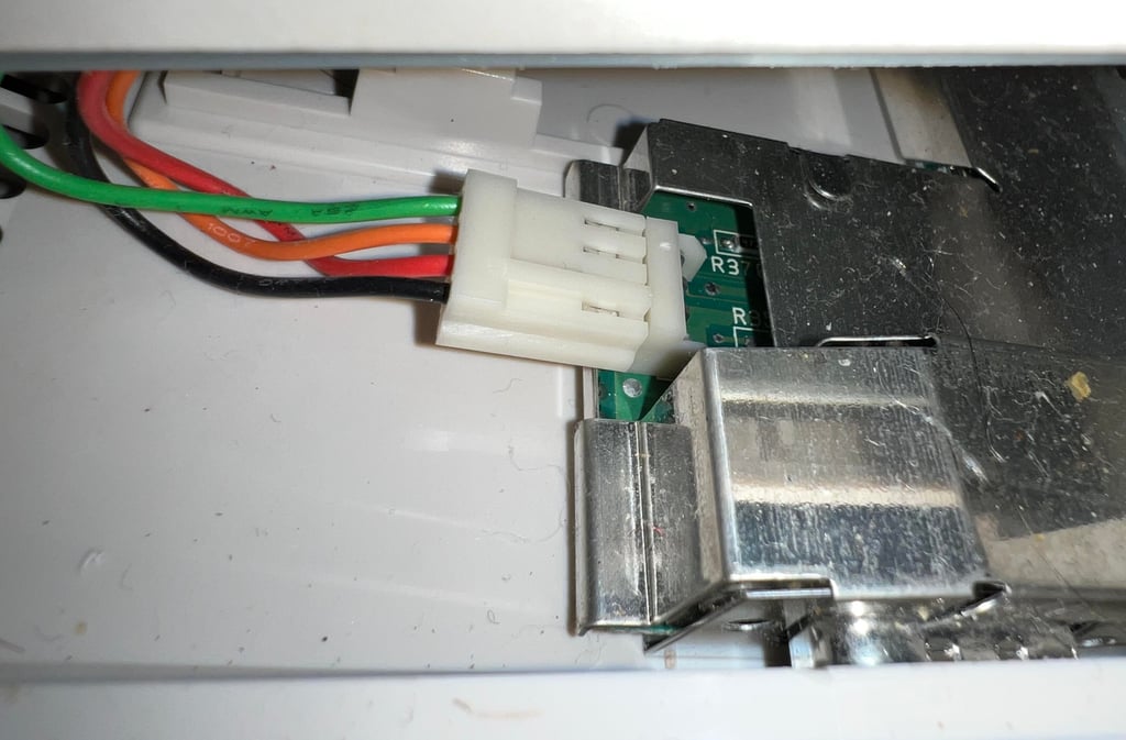
To remove the internal disk drive the small screw (see arrow in picture above) is removed. Before the drive is lifted away the power- and data connectors are removed (see arrows in picture below).

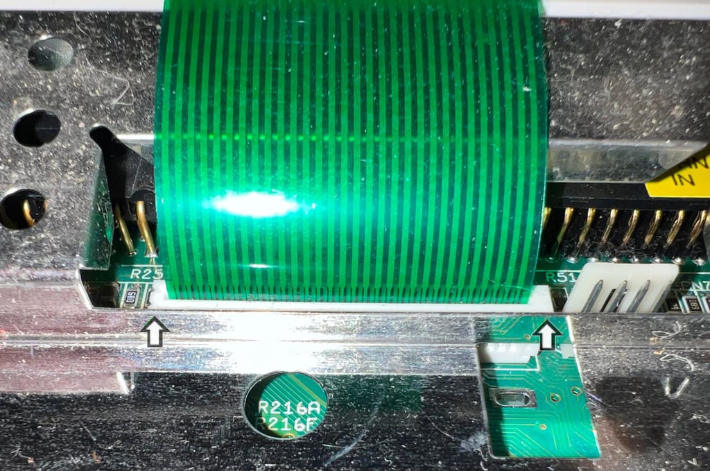
The keyboard ribbon cable is removed next. With a small flat screwdriver the to sides of the cable connector is lifted up (see arrows in picture below). This will unlock the ribbon cable from the connector - and the cable can be carefully removed.

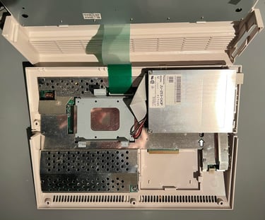
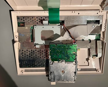
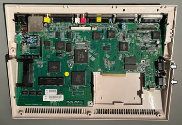
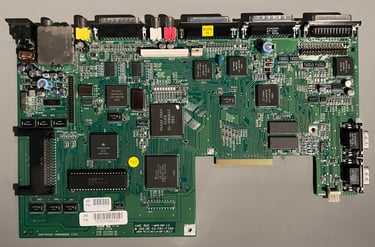
The metal RF-shield is mounted with one screw (middle / bottom) and 11 folded metal tabs. These metal tabs are lifted to an upright position and the screw removed. The PCB is now revealed in all its glory. It looks to be in good condition. I can not see any immediate damage.

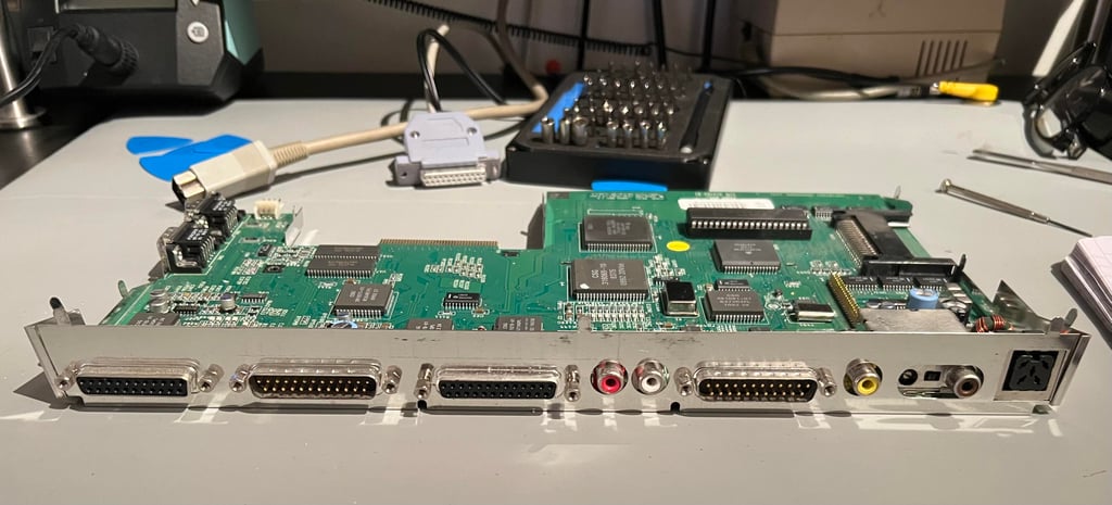
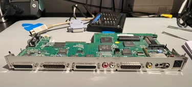
To lift the PCB out of the bottom cover can be a bit tricky. It is a tight fit, but the way I remove the A600 PCB is to carefully pry the two ports from the right side of the bottom cover. And then lift and tilt the PCB straight up. But it is important to be careful to not damage the old plastic. When the PCB is out of the bottom cover the hex nuts are removed from the bottom metal shield with iFixit tools.
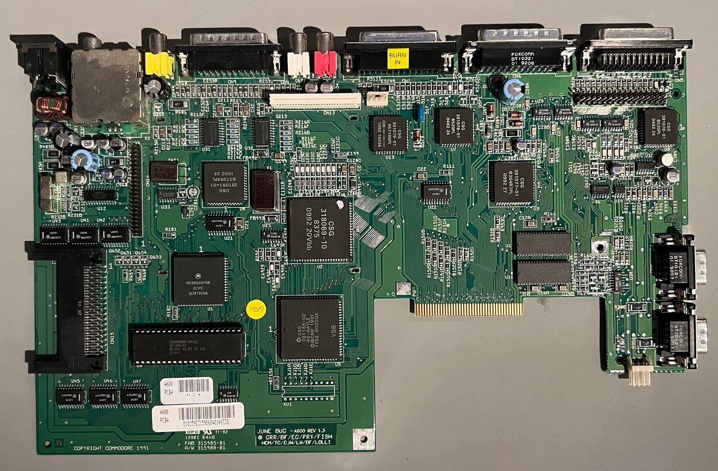
Mainboard
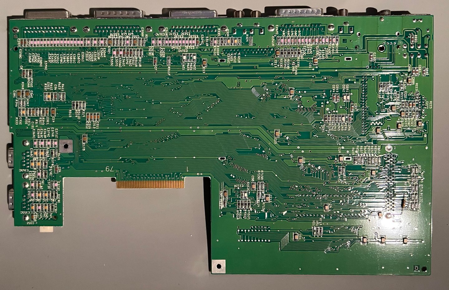
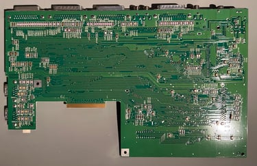
The mainboard is a FAB 315985-01 / AW 315988-01 Rev 1.3 (June bug). It appears to be in good condition, I can not see any damage or corrosion at first sight. Nevertheless, these old SMD electrolytic capacitors have more than likely leaked.
Replacing the electrolytic capacitors
To replace the SMD electrolytic capacitors the need (obviously) to be removed first. There are three (as I am aware of) ways to do this:
Twist and pull
Hot air and kapton tape
Cut and desolder
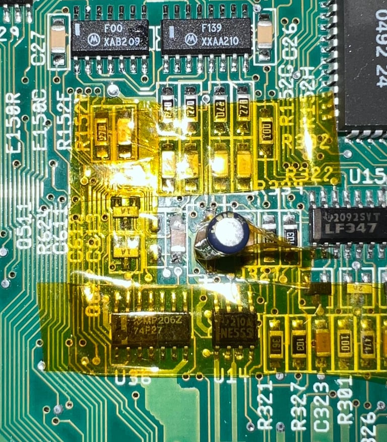
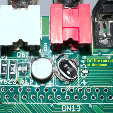
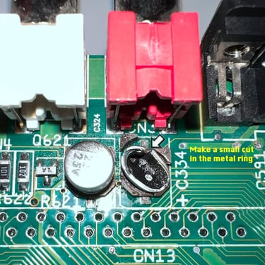
My preferred way of removing SMD capacitors is the "Cut and desolder" method (AKA the Chris Edwards way). This is probably the slowest method, but I find it the most careful. In short, the capacitor is held down while cut close to the bottom with a bent cutter. Then the remaining "ring" is also cut, the inner rubber parts are removed with a pair of tweezers and finally the legs are cut and desolder. In addition to a slow process, you also get the fun of the old fishy electrolytic smell. Oh my...
In the table below the different electrolytic capacitor values used for the A600 is shown.
Replacing the electrolytic capacitors (except the SMDs between the audio- and keyboard connector)
IMPORTANT NOTICE (aka spoiler alert)#1: It takes three (!) attempts to replace these capacitors. And in the last attempt I use through hole capacitors since these are easier to get by with an oscilloscope probe!
IMPORTANT NOTICE (aka spoiler alert)#2: In the pictures below all pads are fine and healthy. Cutting, desoldering and soldering the two first attempt was done without any damage to traces or pads. But in the third attempt the (+) pad on C239 and (-) pad on C304. On the latter a small bodge wire is connected to R302 (POS). I forgot to take pictures of these unfortunately, but it is important to be aware of this if in need for future repair.
I previously mentioned that I use the method of "cut and desolder" all the SMD capacitors. From my experience this is the most gentle method in regards of reducing the risk of damaging the pads or traces. In addition the soldering temperature should not be above 360 degrees Celcius. Below are some pictures of the areas after cutting and desoldering.
When removing the capacitors it is obvious that this was in due time. Several of the capacitors had leaked and the odour was really terrible (smells like old rotten fish). But I was quite happy with the clean-up with vinegar and isopropanol. Most (all?) of the electrolytic dielectric and corrosion is gone.


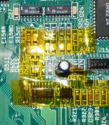
The result after the first re-cap attempt:
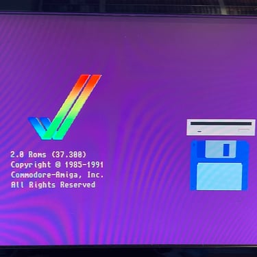
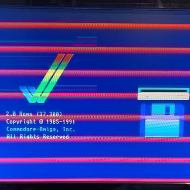
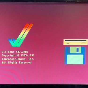
Picture is not always displayed correctly. Sometimes the pictures is looking ok, sometimes the "R" in the "RGB" colours are missing and sometimes other video disturbances are present. See pictures below.
The machines does not always get out of reset (black screen for about 60 seconds or looping several times before stabilizing). NOTE: I am not 100 % sure that this was not an issue before re-cap as I only powered the A600 on for a single time. But my hypothesis is that it is provoked by the re-cap either by leakage damage from the capacitors, short circuits or bad connection(s).
First troubleshooting
As I am 99,999 % sure that the A600 worked before re-cap my hypothesis is that the fault is caused by a bad soldering, a broken trace, a short circuit or a faulty capacitor. After quite some time checking for connectivity issues, short circuits and faulty capacitors - and not finding anything wrong - I decide to remove the newly installed capacitors and do the operation again. It must (?) be something caused by the soldering or that there are areas of leakage which I have not been able to remove. Or that these areas of leakage has now been accelerated and actually damaged something.
Replacing the electrolytic capacitors (except the SMDs between the audio- and keyboard connector) - 2nd try
With the same method (cut and desolder) all the capacitors are removed. None of the traces or pads were damaged during this operation. I do not have any pictures of this unfortunately, but all traces and pads were checked thoroughly. And no faults were detected.
The result after the second re-cap attempt:
Exactly the same (!). The picture is lacking quality and the machine has an issue with not starting or going into a reboot loop.
Second troubleshooting
This was not what I expected. I was quite confident that a poor solder work, or obvious leakage, was the issue. Of course, there is a chance that a poor solder work can be done twice, but I do not really see that very likely. And if the solder work was bad, how come that the poor work was done on the exact same capacitors?
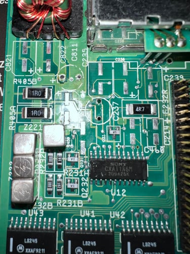
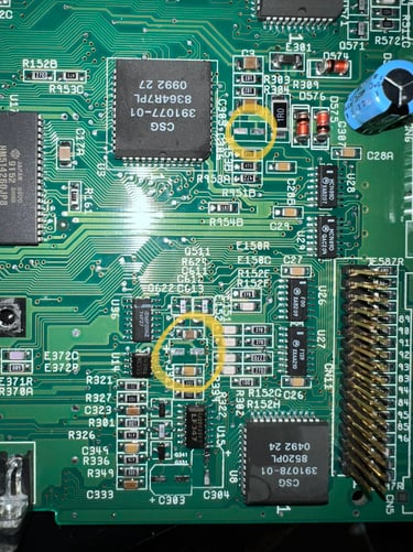
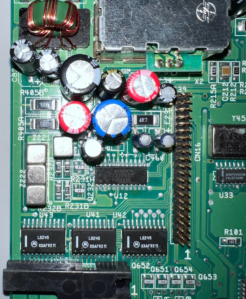
So my hypothesis starts to shift towards issues with the Sony CXA1145M RGB video encoder and/or the 555-timer. The first one is responsible for producing an analog videosignal (RGB) and the latter plays an important role in the reset circuitry.
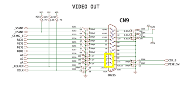
About 80 % of the times the boot screen appears, but missing the "R" colour component (the "G and B" are present). 10 % of the times the screen appears with other disturbances and 10 % of the times the screen is ok. So I try to focus on the RGB video signal components from the Sony CXA1145M chip on pin #21, #22 and #23. See schematics below. Also, as a matter of fact, when the "R" component is missing from the RGB signal the signal from the RF-modulator and the composite videosignal are ok! Both of these have the "R" component...
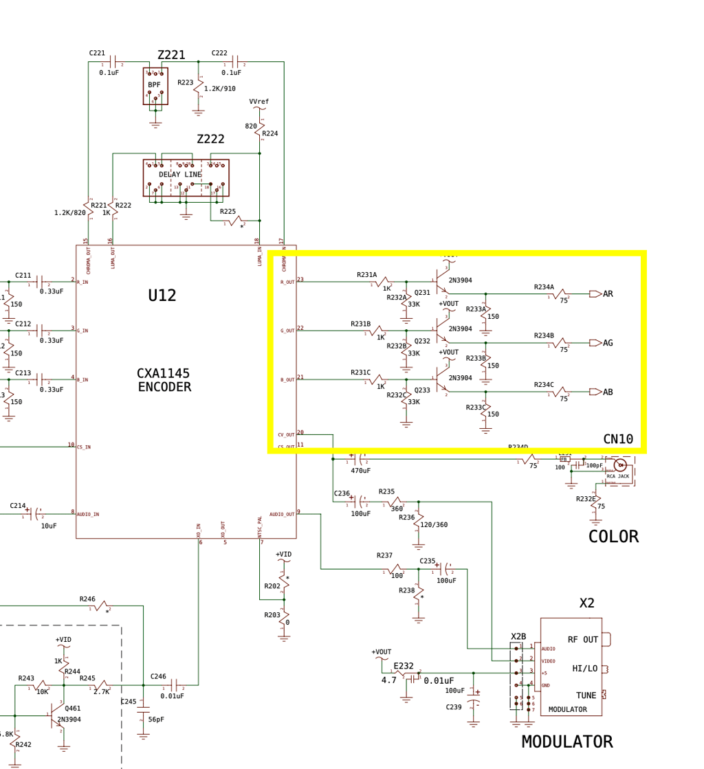
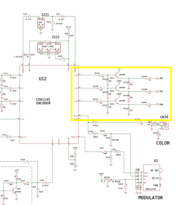
Measuring both directly on the Sony IC and the points "AR", "AG" and "AB" (by the resistors R234x) - all signals looks perfectly fine. When showing the white colour at bootup (when all the three colours are set to maximum R=G=B=$FF ) the signals on all these three pins looks identical. So it appears to me that the Sony IC is working fine. Note that these are the analog RBG signals (therefore the "A") which are exposed to pin 3, 4 and 5 on the 23-pin D-sub video connector. It is these signals that I check on my TV set. See schematics below.
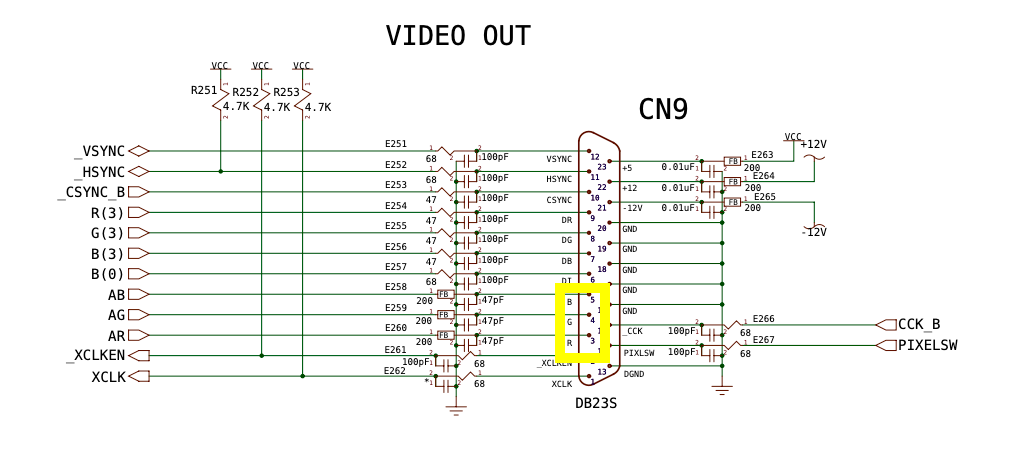
And now to the obvious question: is the "AR" signal present on the ferrite bead E260? Well, eh, ok, this is getting embarrassing... I don´t know. For reasons I do not know I did not check this before moving on to troubleshooting the 555-timer. Sorry... this calls for "buksevann".
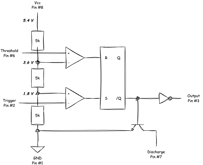
The principles behind the 555 timer is not very complicated. This device can be used for many purposes, but for the Amiga 600 (and other Amiga/Commodore machines) the 555 timer is used to reset the machine. In the schematics below the inside of the 555-timer is shown. To reset the Amiga 600 the 555-timer is initially in a "SET(S)" mode, but when the voltage on PIN #6 reaches above 2/3 of the VCC the 555-timer will go to "RESET(R)" mode.

Now things starts to get interesting. It turns out that the machine fails in two modes:
The A600 does not come out of reset: the threshold voltage is struggling reaching > 2/3 VCC.
The A600 resets in a loop: the threshold voltage reaches > 2/3 VCC, discharges the C612 capacitor and then the trigger voltage falls below 1/3 VCC.
I do not see any obvious reason for this behaviour. But as can be seen in the schematics below for the reset circuitry there are two capacitors which are used in relation to the threshold and trigger voltages; C612 and C611.
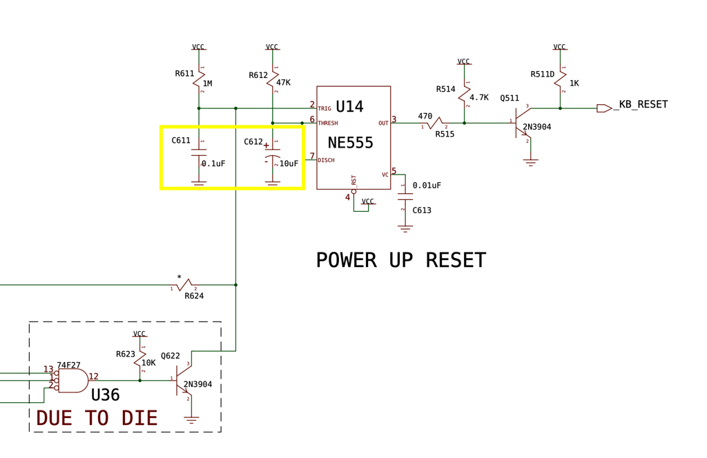
Since the C612 is a newly replaced SMD capacitor I decide to desolder this and replace it with a 10 uF TH capacitor just to rule out any faults with the SMD soldering. The result is the same. Either struggling to start (we are talking 30 - 60 seconds before exiting reset) or a reset-loop. Next I try to add some fresh solder to each end of C611, but with no change in result. Finally I decide to desolder the C611 to verify that it actually works out of circuit.
To desolder the C611 some hot air is used while the surround components are protected with some kapton tape.
It turns out that the C611 ceramic capacitor is working fine and have the capacity of 0.1 uF. At this point I decide to remove all of the new capacitors - and try with some TH electrolytic capacitors.
Why? There has to be some damage that I either have done during soldering. Or some leakage damage which I still have not detected. And with through hole (TH) capacitors it is somewhat easier to probe the pads with the tip of the oscilloscope. You could argue that I could spend more time on investigating, but I think the most effective way is just to repeat the whole operation.
Third troubleshooting
The installed SMD capacitors are "cut and desoldered". This operation works very well even the third time (!). But when installing new TH capacitors two pads are lifted due to heat:
(+) pad on C239
(-) pad on C304
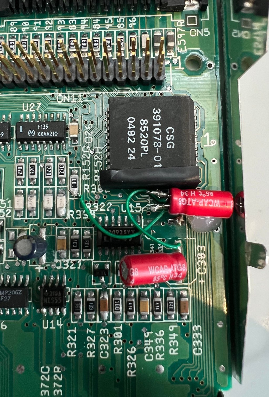
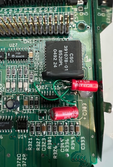
A small bodge wire is wired from (-) on C304 to R302.
Below is a picture of the area with TH capacitors instead of the regular SMD capacitors. I agree it does not look as "hot" as SMD, but the capacitors works the same.

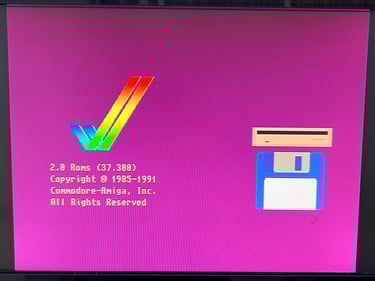
And now something happens: with the new (!!) capacitors installed the machine boots and the picture is back! Nice!

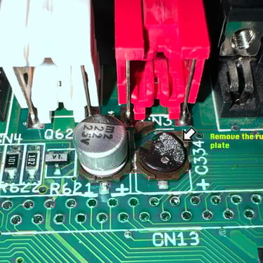
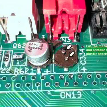
Re-capping the C324 and C334
There are two 22 uF SMD capacitors stuck tight between the keyboard connector and the phono jack connectors. My way of re-capping these two is to first desolder the whole keyboard connector. I know that this takes much more time, but I do not like the idea of accidentally melt either the phono jack connectors or the keyboard connector. The keyboard connector is removed without any damage to traces or pads. See picture below.
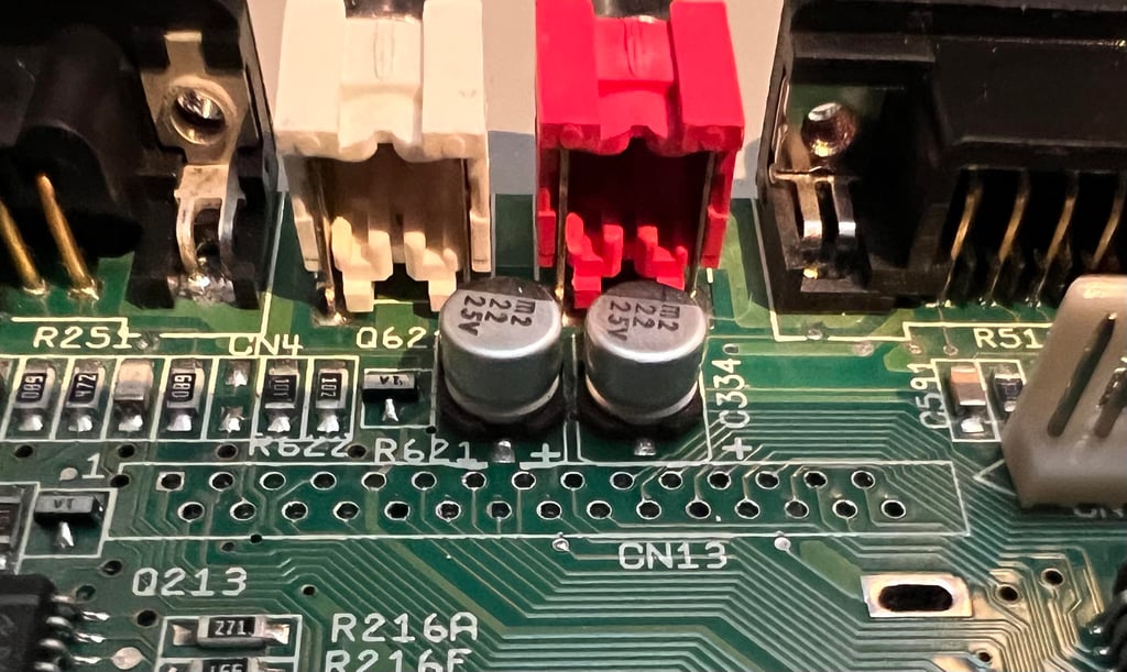
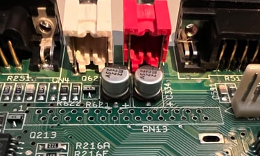
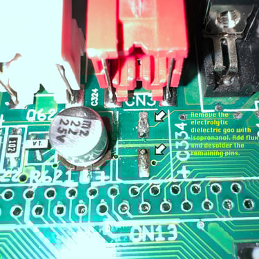
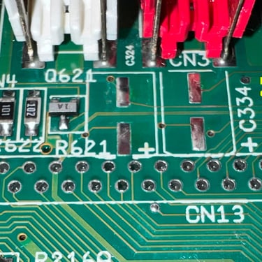
As with the re-cap on rest of the mainboard these capacitors are also removed by the "cut and desolder" method. In the gallery below pictures of this process is shown (click to enlarge).
Sound issues
After the third recap the mainboard seems to be working ok. The reboot issue(s) are gone and the video signal appears to be fixed. But I do notice by using the oscilloscope that the audio signal is not working as expected. There is sound , but it appears that the sound is marignal or disturbed. After quite some investigation it turns out the that there is a broken trace on both the (+) and (-) pad on the C304. This is fixed by adding bodge wires for both of these - and gluing the C304 to the mainboard.
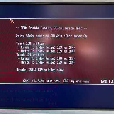
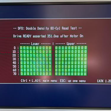
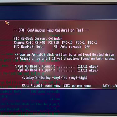
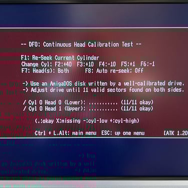
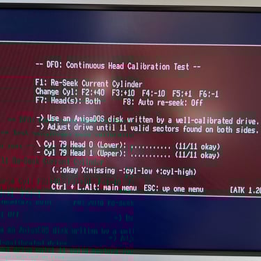
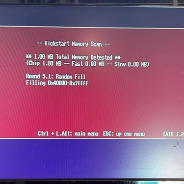
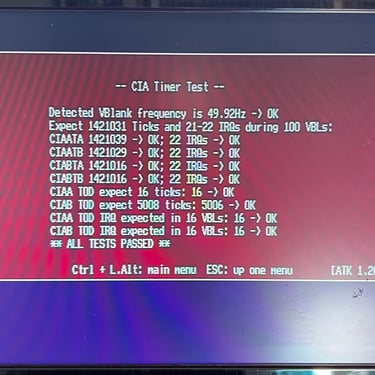
Testing
This recap work should be a straightforward operation, but turned out to be quite tricky. And the thing is that I do not really know what happened? I never found any broken trace og pad, or short circuit, from the 1st and 2nd re-cap. Only after the 3rd re-cap things started to work again. This will probably be a mystery forever...
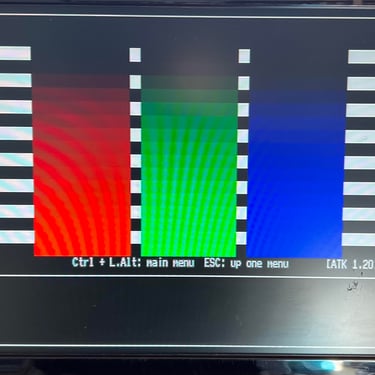
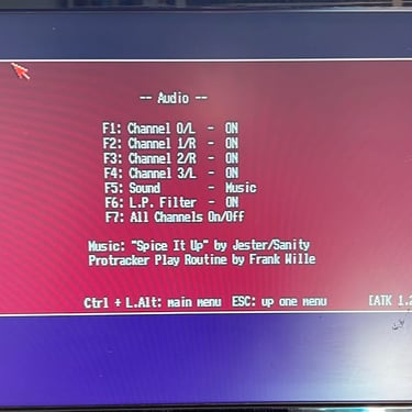
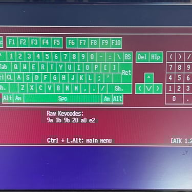
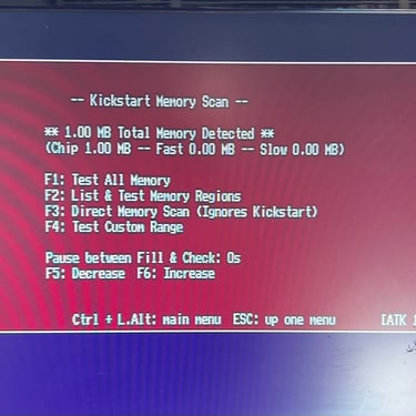
Nevertheless, when testing the A600 things seems to be working as it should now. See pictures below (click to enlarge).
"Are you keeping up with the Commodore? 'Cause the Commodore is keepin up with you!"
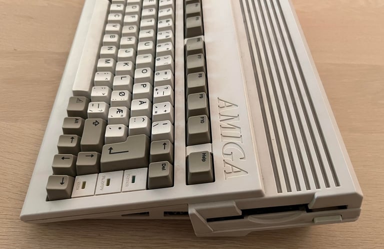
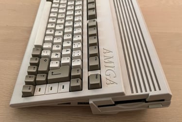
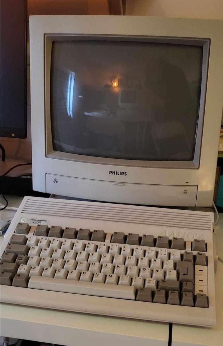
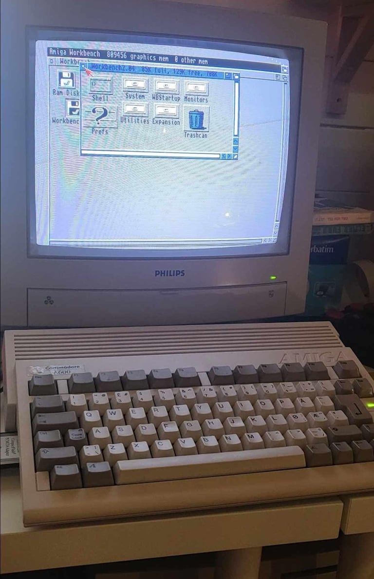
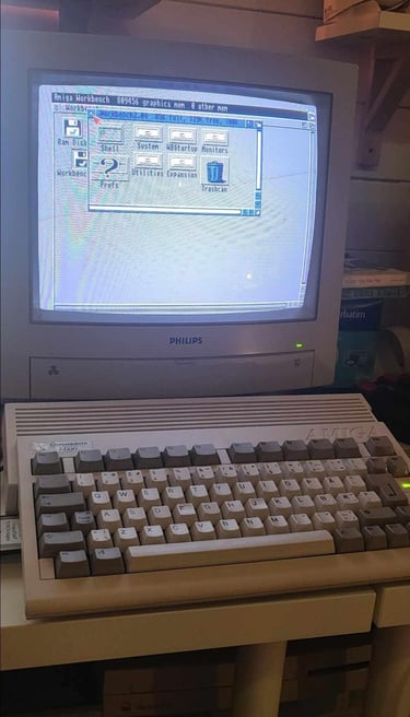
Below are some pictures of the A600 back at the customer´s home!

Banner picture credits: Ajne01 - Own work, CC BY-SA 4.0, https://commons.wikimedia.org/w/index.php?curid=122012162