
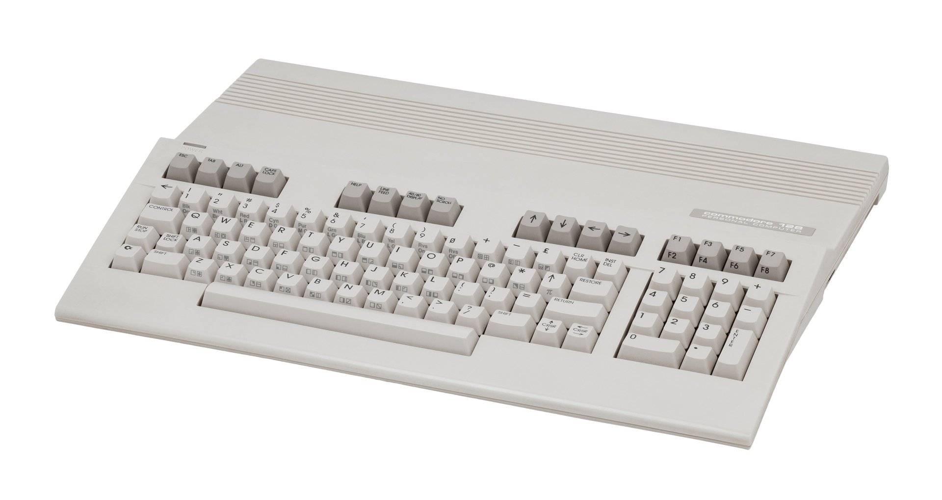
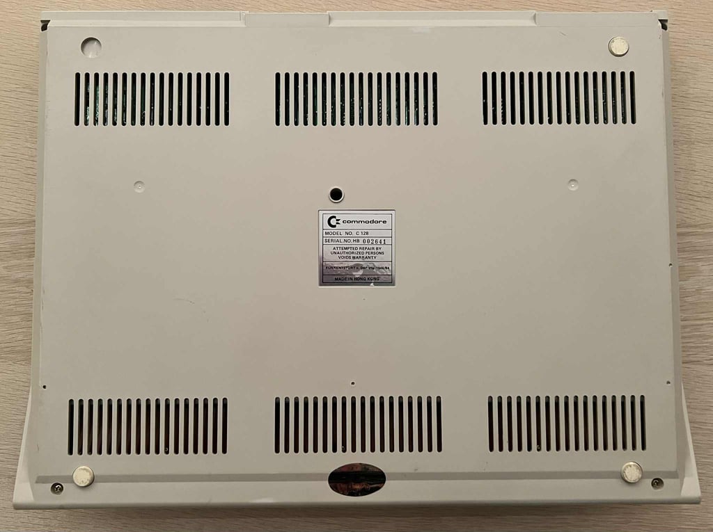
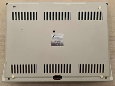
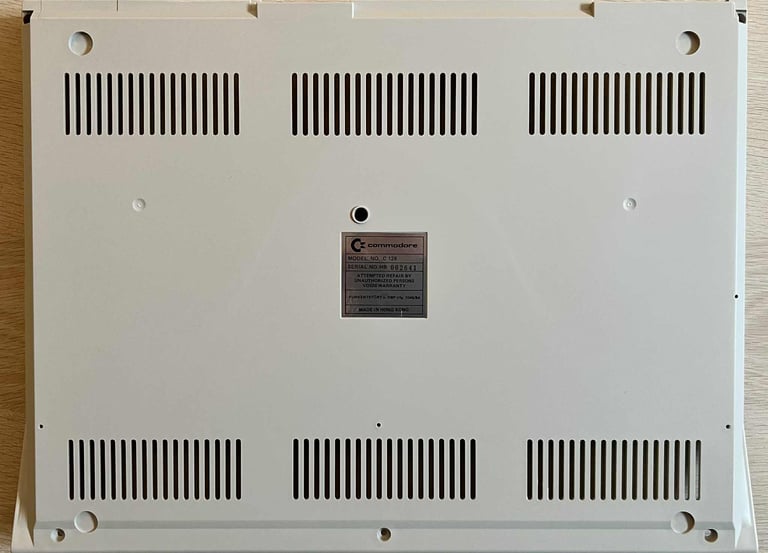
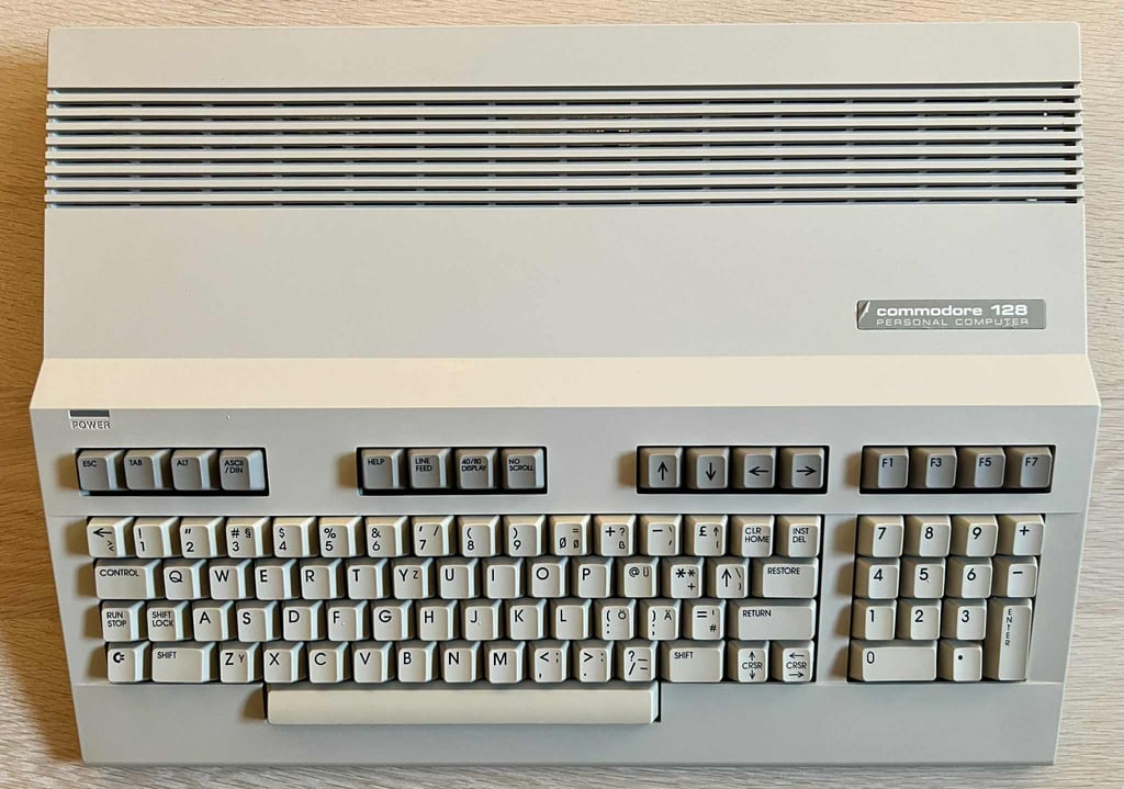
C128 [PAL]
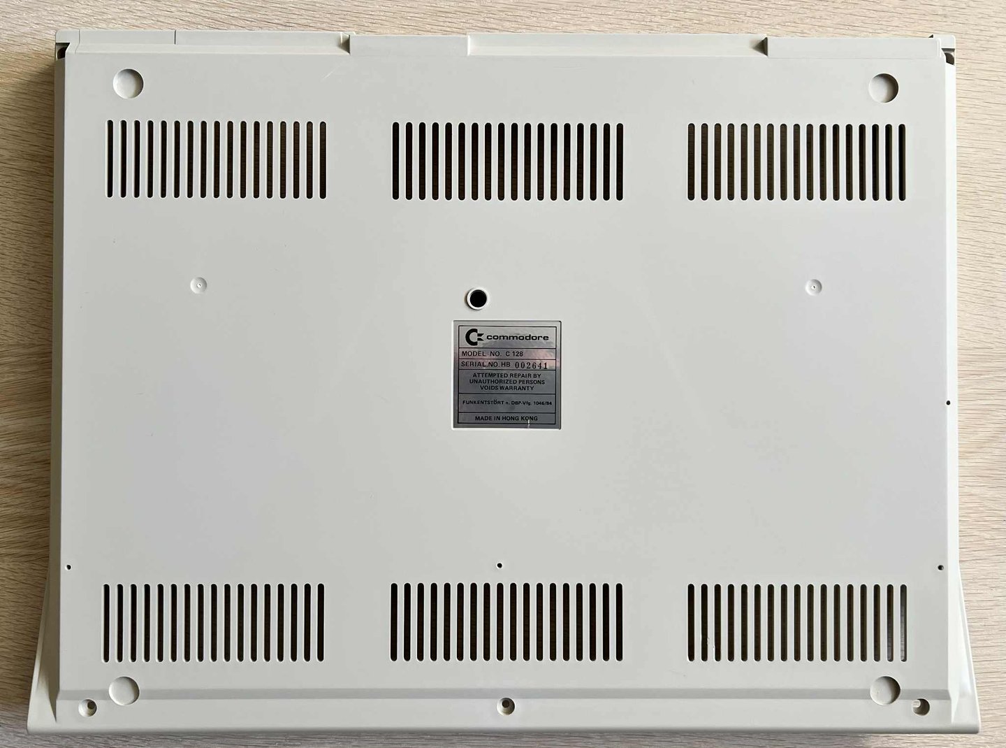
Ser. No. 002641
Artwork 310381
(REV 7)
Starting point
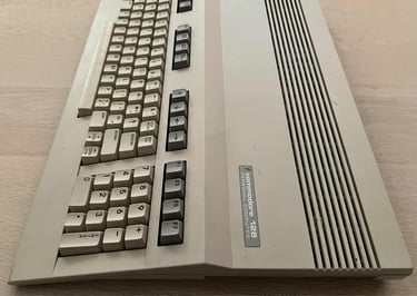
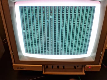
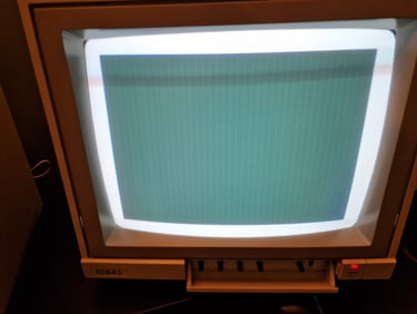
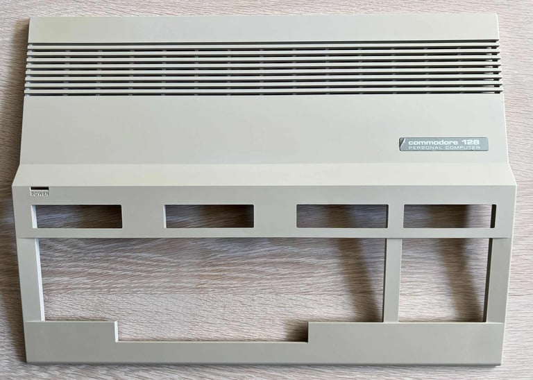
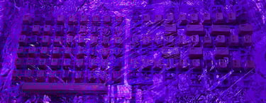
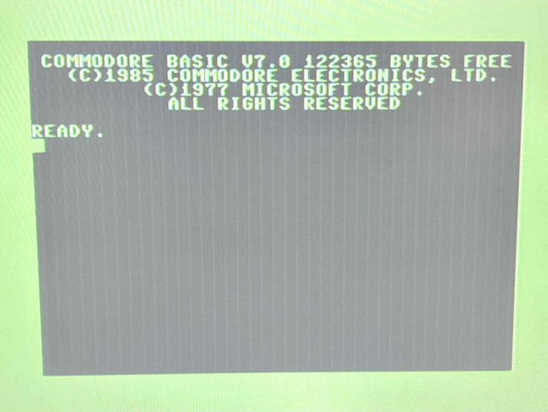
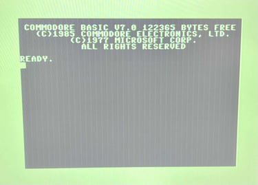
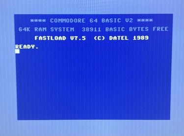
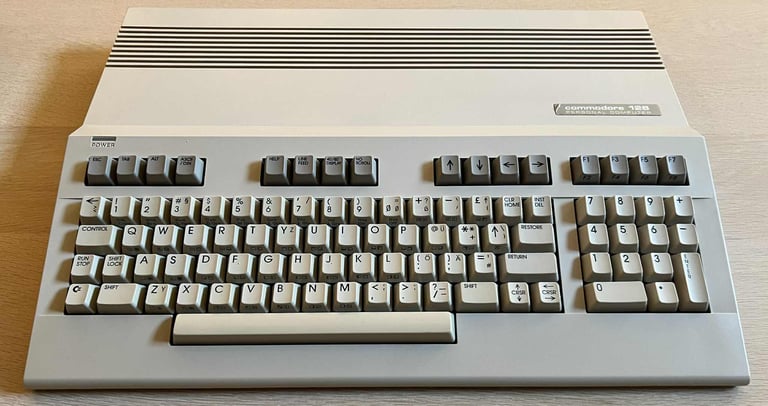
Executive summary; dirty, yellowed, but in otherwise good looking condition. But inside there is something going on... this machine is reported to be not working as it does not display any proper boot-up picture when powered on (see pictures below). It shows some garbled screen first, and then goes blank. At first I did not notice, but there is a missing plastic bridge on the backside of the machine (surrounding the cartridge port).
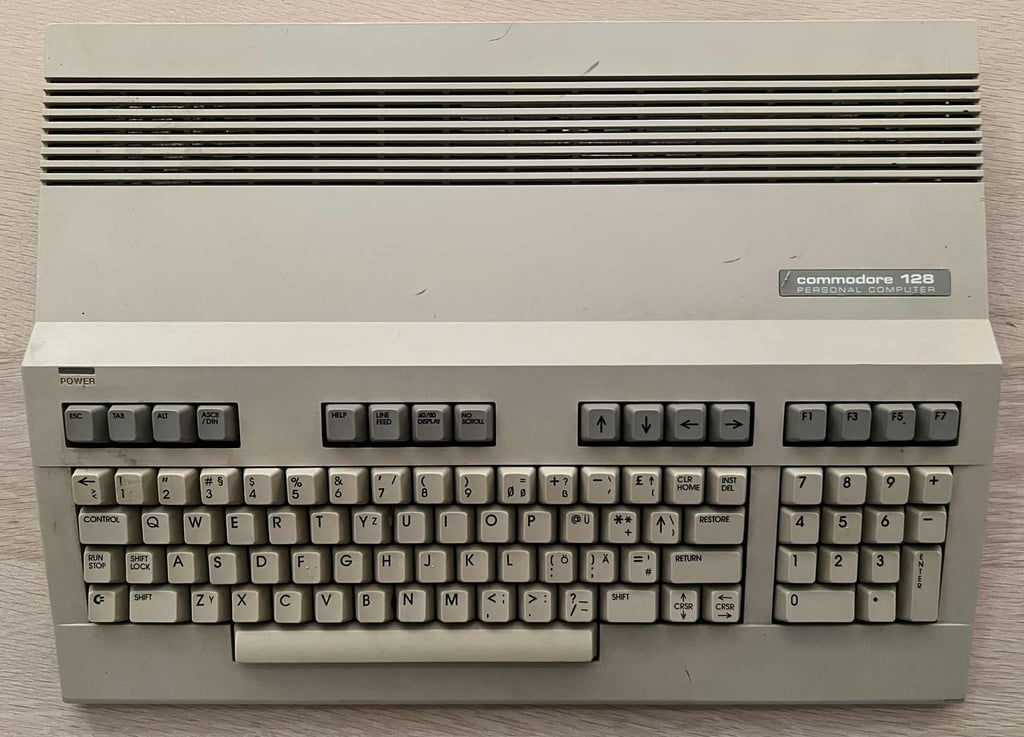
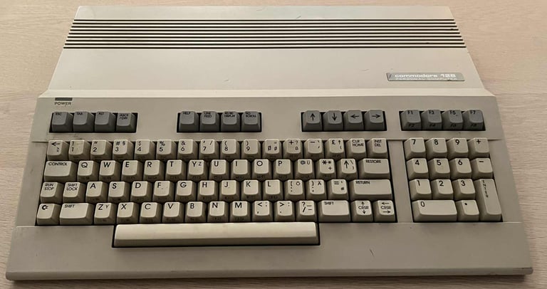
Nevertheless, a bit more detailed of the first exterior visual inspection:
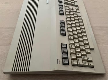
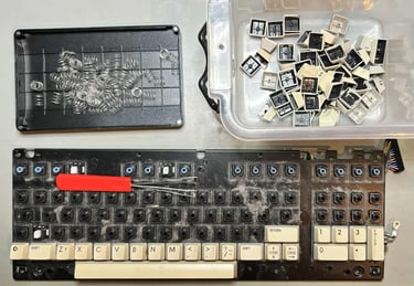
The machine is quite dirty. There are dust and grime, and quite a few stains, on both the top- and bottom cover.
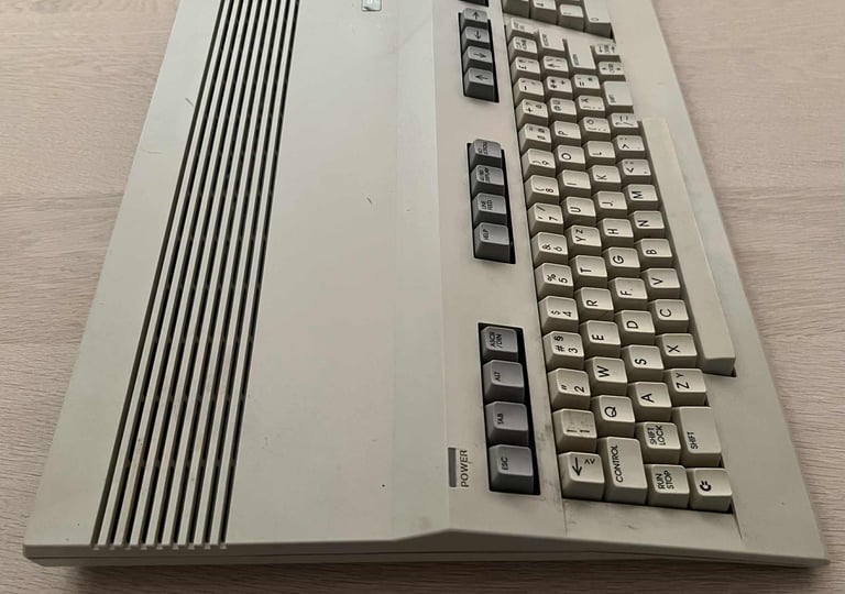
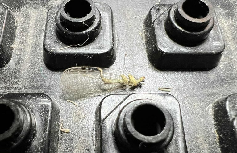
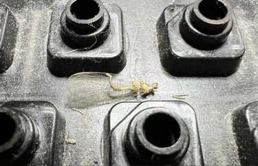
Between the keycaps there are a large amount of dust. I think can also see some wings (?) from an insect.
Both the cover and keycaps are yellowed. But it is not too yellowed I think. These will be retrobrighted, but the yellowing is not too bad actually.
One rubber feet is missing on the bottom cover.
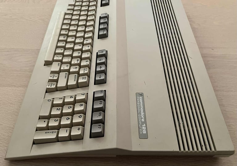
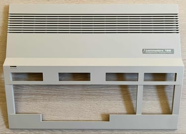
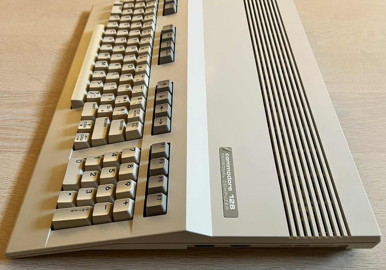
The protective seal over the "Commodore 128" badge is still present.
The machine appear undamaged from a mechanical perspective. I can not see any visual damage to it.
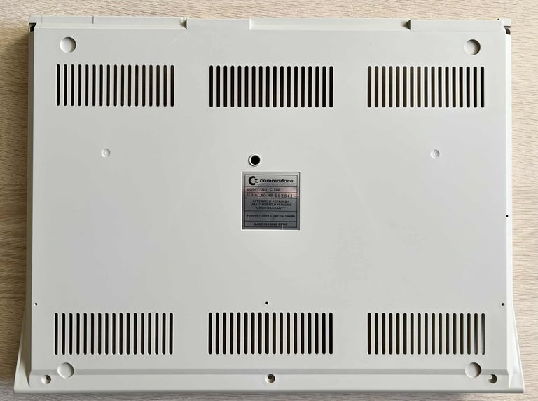
The warranty seal is not broken. This machine has probably never been opened before (!)
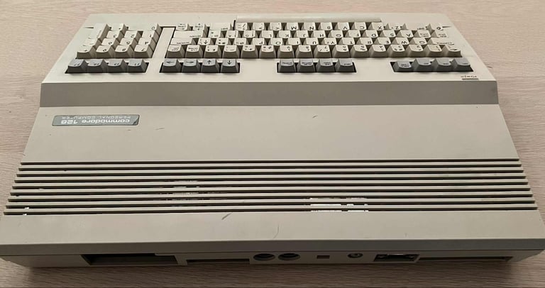
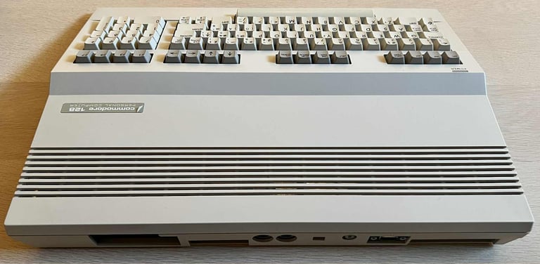
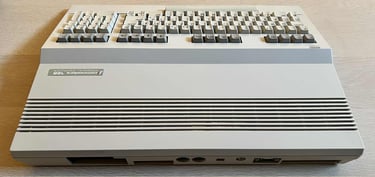
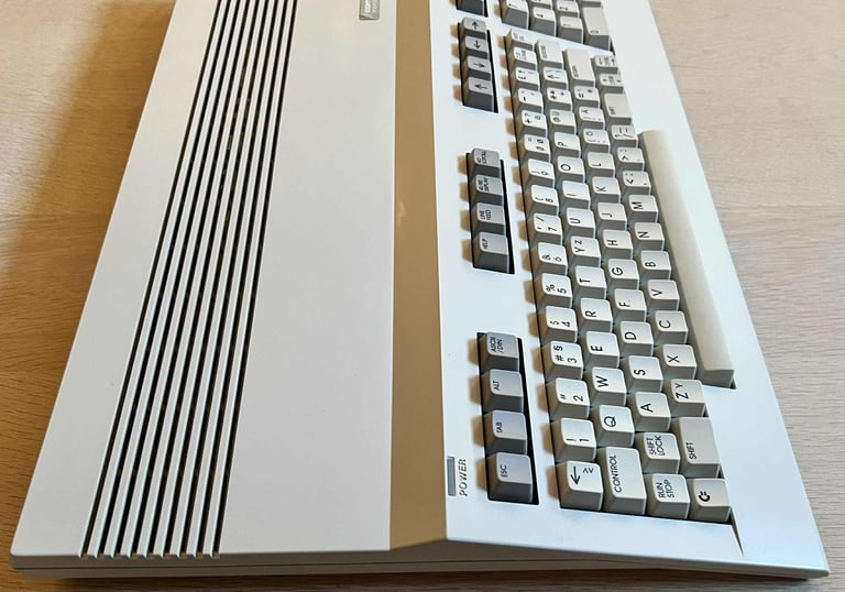
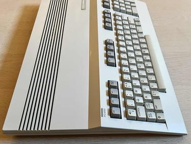
Broken plastic edge/bridge above the cartridge port
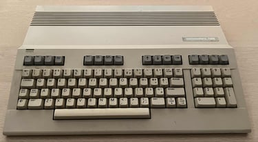
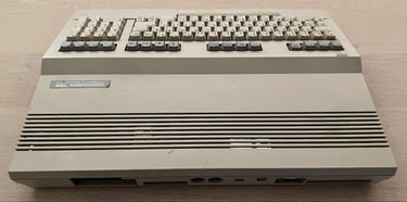
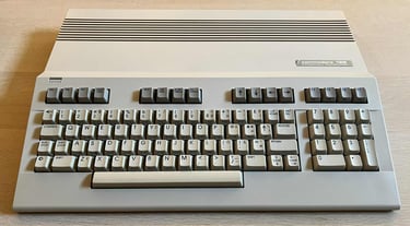
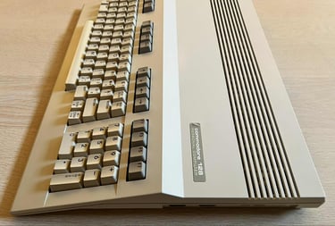
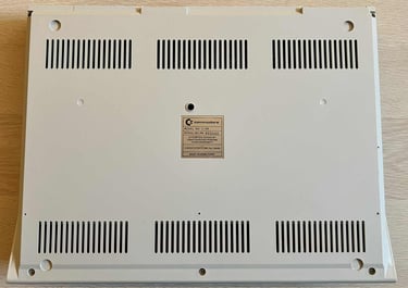
Below are some pictures of the machine before refurbish.
As mentioned the machine is currently not working. Below are some pictures, taken by the owner, from the display at power on.


Refurbishment plan
The refurbishment plan for this flat C128 (several of them in parallell):
- Refurbish the casing (cleaning, repairing and retrobrighting)
- Refurbish the keyboard (cleaning, reviving the plungers and retrobrighting)
- Refurbish main board (cleaning, checking, repairing etc.)
- Verify operation by testing
The plan can be updated during the refurbishment process. Sometimes I discover areas that needs special attention.
Disassembly
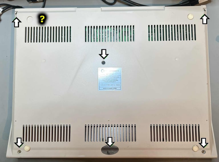
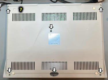
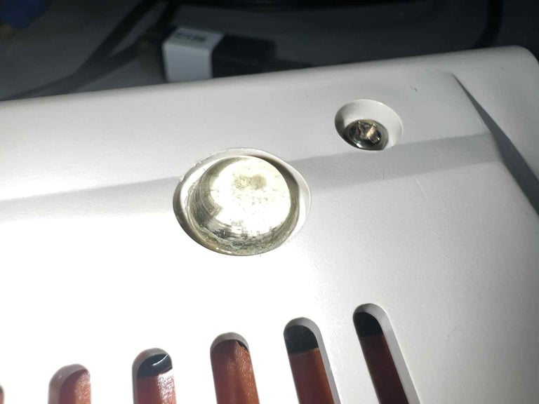
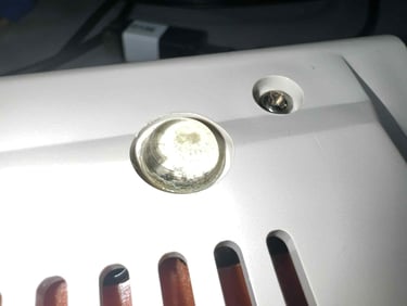
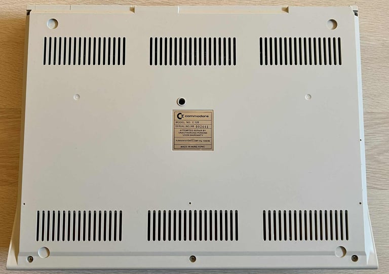
First action in the disassembly of the C128 is to remove the six 3 x 8 mm PH2 screws at the bottom of the machine. Make sure to use a low torque screw driver when doing this. As can be seen in the picture below, three of the screws can be found in the front, one in the middle and two at the back. One of the screws is also covered by the warranty seal which needs to be removed.
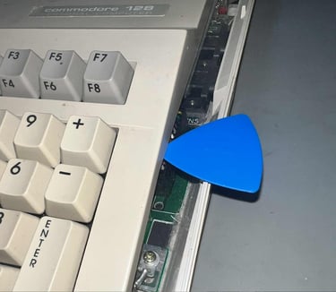
With the six screws out of the way, the top lid can be partly lifted. To do this a some spudgers are inserted between the top- and bottom cover. A small plastic clip is located on both the right and left side - just above the top of the "+" and "LEFT ARROW" keycap. See picture below for the right hand side.

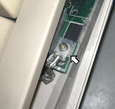
Before the top cover can be lifted completely, the ground wire on the right hand side must be removed. This screw has the same dimension, 3 x 8 mm PH2, as the screws holding the back cover.

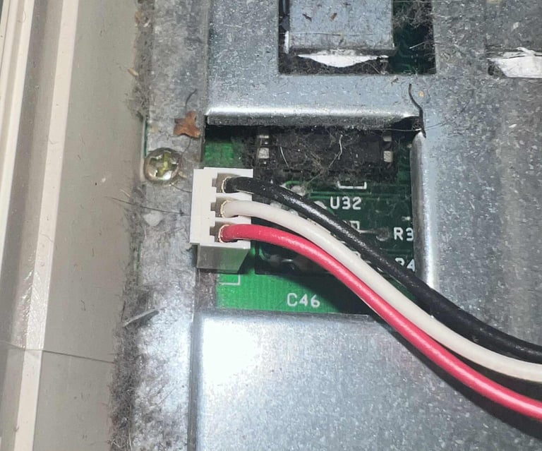
Next, the LED connector on the left hand side is removed.

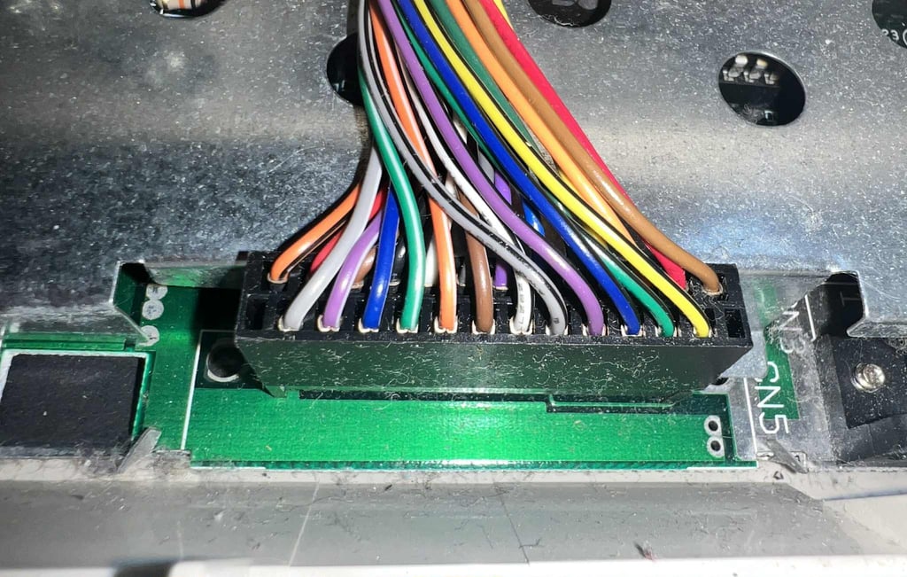
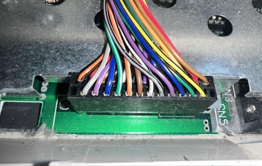
We´re not completely out of the woods yet. Before the top cover can finally be lifted off, the keyboard connector must be removed. This connector can be hard to remove with bare hands, so a thin flat screwdrive can be helpful to loosen the connector from the mainboard.
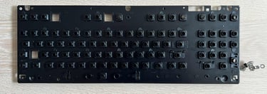
The top cover, and keyboard, is lifted off and the mainboard covered with a large RF-shield is exposed. And there is a lot of dust and grease inside here. The picture does not do it justice, there is a lot more dust and grease than can be seen.

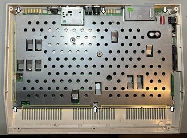
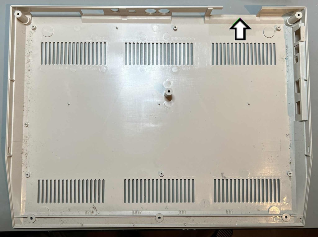
To remove the RF shield two steps are required. First the six 3 x 8 mm PH2 screws are removed (same screws as the rest - see arrows above), and then all the bent metal tabs (see yellow squared area). When the RF shield is removed the mainboard is exposed. This is probably the first time the mainboard is exposed since it was assembled some time in the 1980s. First impression is that it looks to be in quite good condition, but a more close visual inspection will be done later. But, oh my, there is a lot of dust in here...

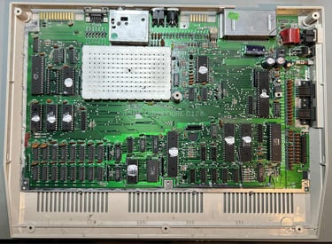
With the screws and tabs out of the way the whole mainboard is lifted from the bottom cover. As can be seen from the picture below the bottom cover is missing a part of the plastic bridge/edge covering the cartridge port. Otherwise it appears to be in fine, but dirty, condition.
Casing
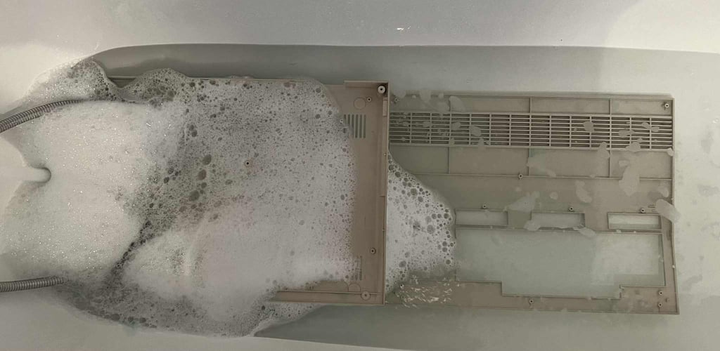
Both the top- and bottom cover are full of dirt and grease, and also slightly yellowed. First action is to clean the covers. Both covers are placed in mild soap water for about 48 hours straight. This will dissolve most of the dust and grease.
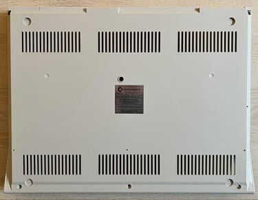
After cleaning the top- and bottom covers looks way better. They are still somewhat yellowed, but cleaning them made a huge difference. To get the stains removed from the covers a combination of a magic eraser and isopropanol was used. Below are some a pictures of the covers after cleaning - but before retrobrighting.

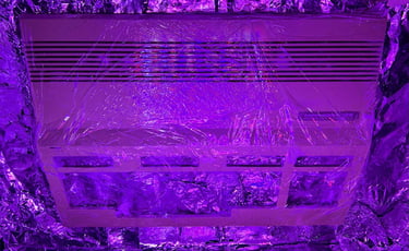
To tackle the slight yellowing the top- and bottom covers are retrobrighted for about 12 hours straight. Some 12 % hydrogen peroxide cream are applied regularly during the 12 h period while the covers are covered (no pun intended) in cling film and exposed to UV light.

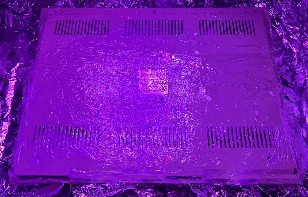

The result after retrobrighting is quite good I think. Most of the yellowing is gone.

As a final touch some transparent rubber feet are added to the bottom cover. These are of course not original, but I think they fit quite nice and since they are transparent they are not impairing the visual look in any way.
Keyboard
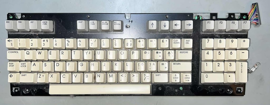
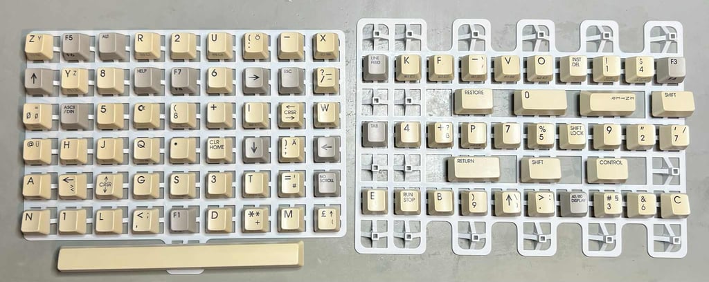
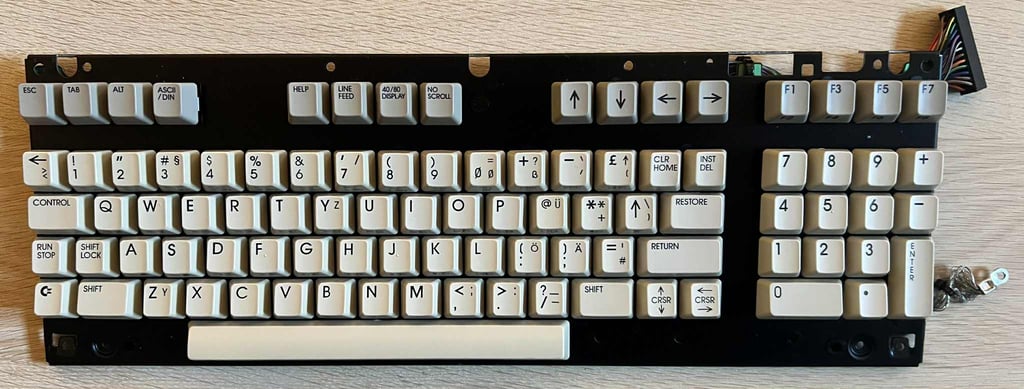
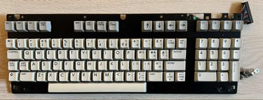
The keyboard is very dirty, but otherwise it appears to be in good condition. The keycaps are slightly yellowed, but not severely. Below is a picture of the keyboard before refurbish.

First step is to remove the keycaps with a keycap puller. Using a keycap puller will both make the removal process faster, but also reduce the risk of damaging the keycaps and the plungers. Note that there is a small spring beneath each keycap, and there are two small additional springs beneath the spacebar. From the picture below you can see the amount of dust and grease beneath the keycaps. Also, a little "bugger" is found - completely dried out (!)
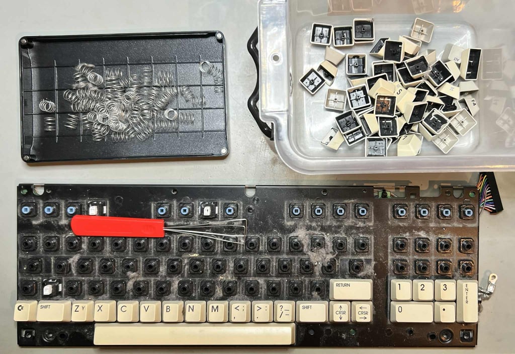
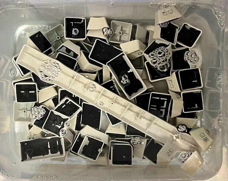
All the keycaps are placed in a box filled with mild soap water for about 24 hours. This will dissolve, and remove, most of the grease and dust.

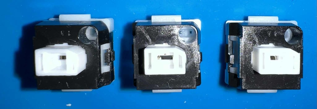
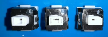
Before the three "click and lock" switches can be removed they need to be desoldered. Note: to remove these switches they must be pushed from the backside of the keyboard towards the front. This will make them pop out without much force.

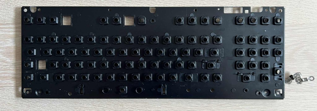
To remove the keyboard PCB all the small screws at the backside are removed. NOTE#1: these screws must be removed with great care. Use a low torque PH1 screwdriver to remove them. NOTE#2: there is a small cable tie that needs to be cut before the PCB can be lifted. NOTE#3: when removing the PCB make sure not to loose the tiny little screw which is situated on the right hand side just above one of the plungers. See picture further down.
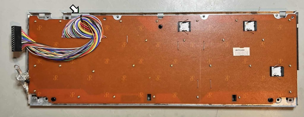
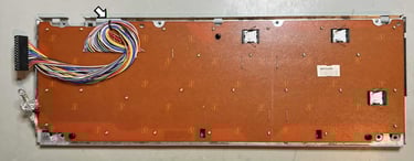
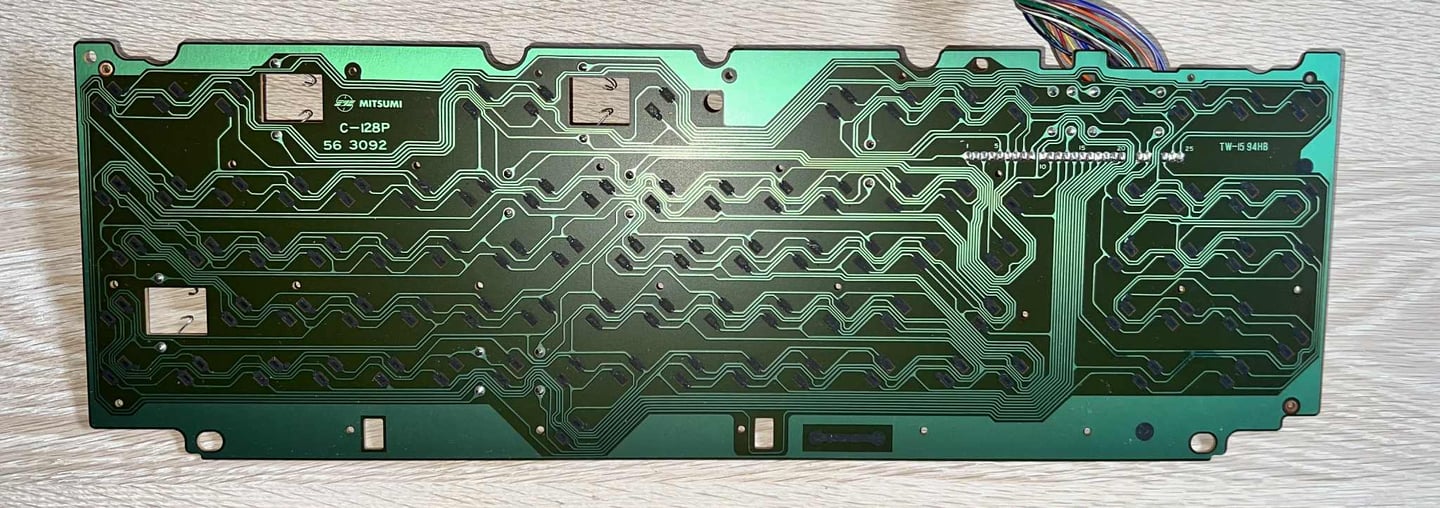
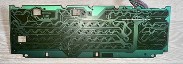
This is a Mitsumi C-128P 56 3092 PCB where the pads are covered with carbon. To clean this PCB only some distilled water is used (no isopropanol which could damage the pads). After cleaning the PCB looks good as new.
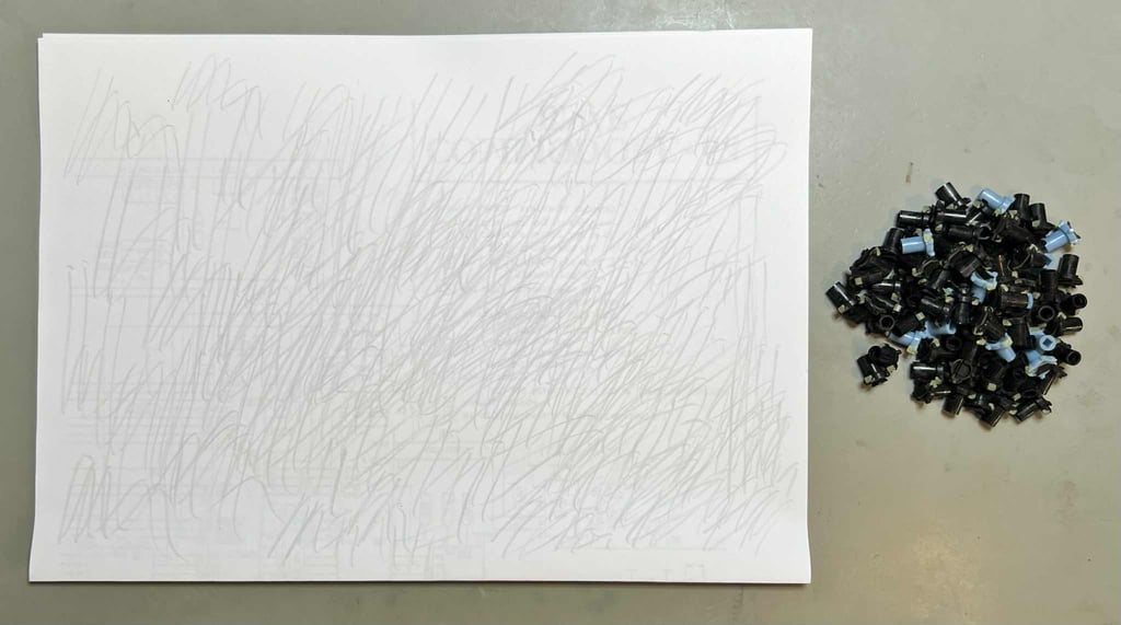
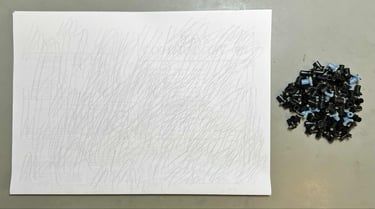
To refurbish the key plungers a neat trick is used: carefully rubbing the conductive rubber on a clean sheet of paper. Refurbishing the plungers will make the keys respond to keypresses better. Note that no isopropanol is used to clean the plungers. Unlike the plungers, the three mechanical switches are cleaned with isopropanol.
The keyboard frame is cleaned properly with mild soap water and a clean paint brush. After cleaning the frame looks good as new.
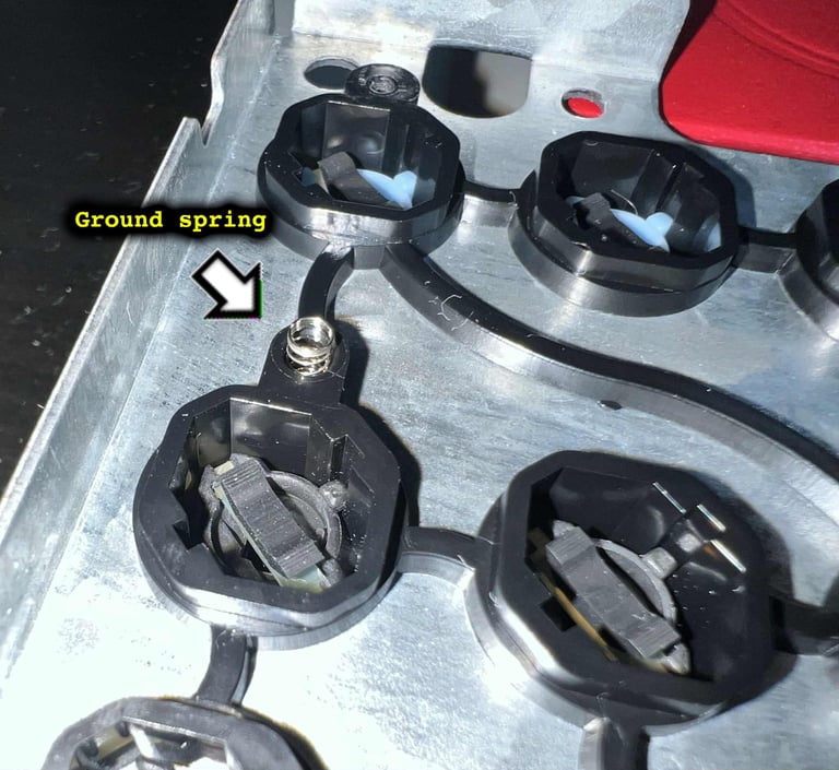
As previously noted there is a tiny spring - used to connect the metal frame to the PCB (ground). The little spring is placed in a small hole just above the plunger situated at the 2nd row far right.

To ease the process of retrobrighting all the keycaps are placed on a 3D printed frame.

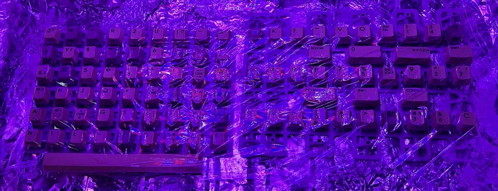
The keycaps are retrobrighted for about 12 hours straight. The 12 % hydrogen peroxide cream is applied regularly to the keycaps. During the retrobrighting process the keycaps are covered with plastic cling film and exposed to UV light.
After retrobrighting the keyboard is re-assembled again. There are some yellowing still, but it is significantly better! Since the retrobrighting is a quite hard process for the keycaps I will stop here to avoid any damage.
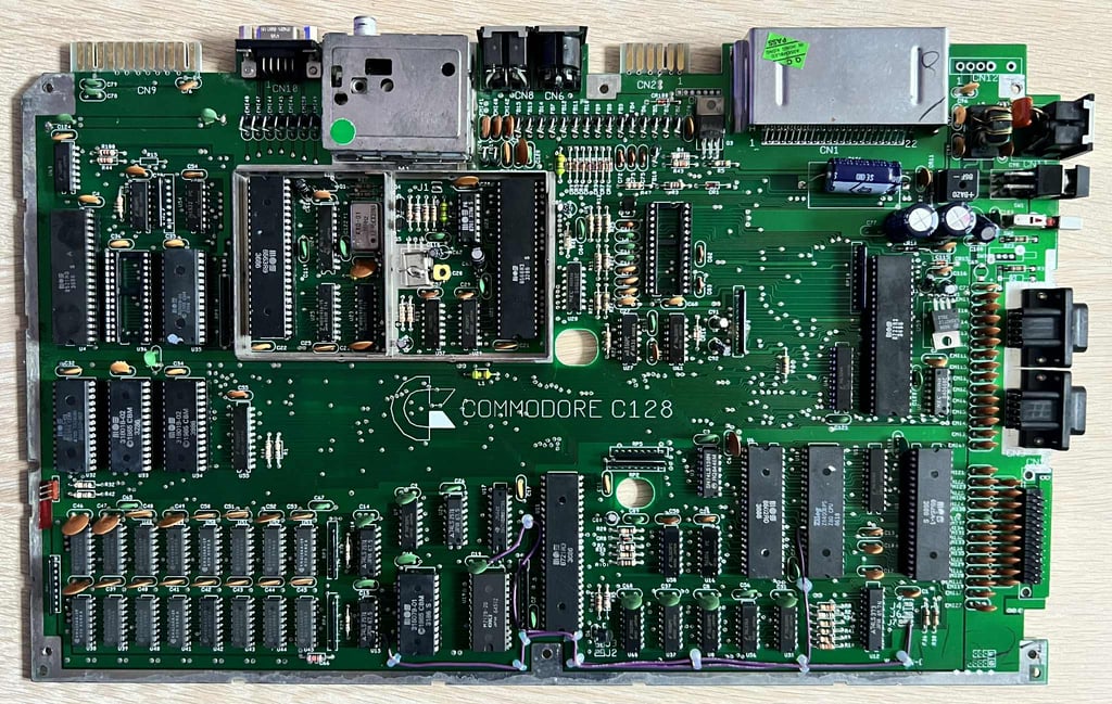
Mainboard
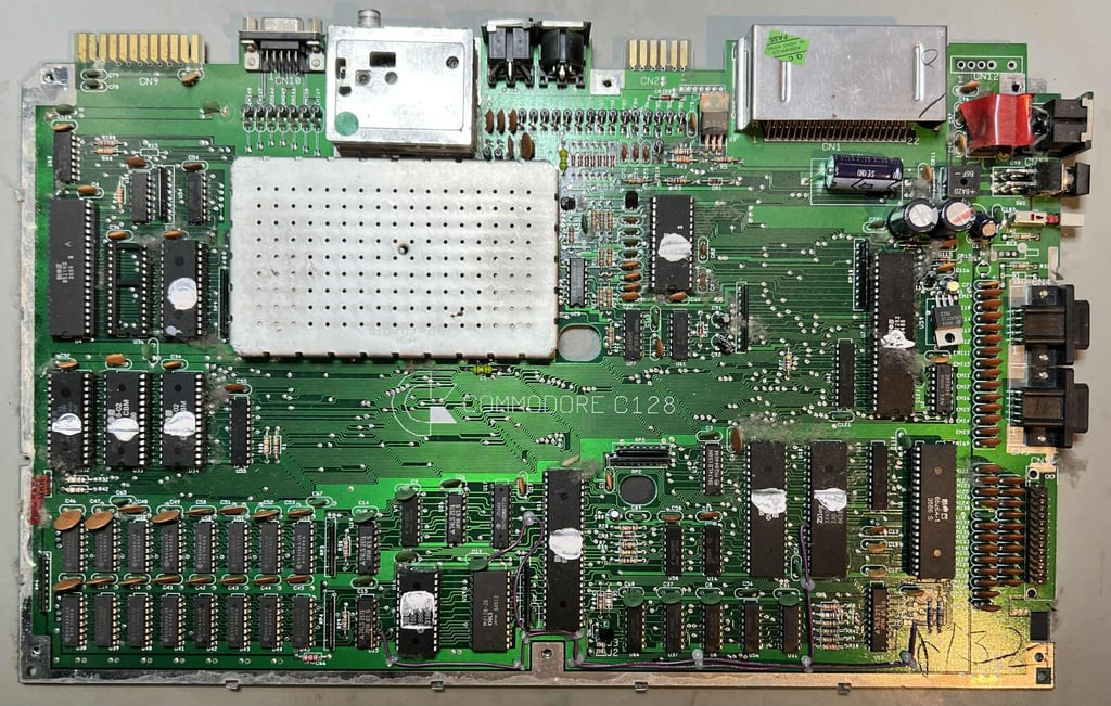
This is an Artwork 310381 / Rev 7 mainboard. Since this machine has probably never been opened since it was assembled I do not expect to find any re-work (or missing ICs for that matter). But the mainboard is covered in a thin, almost invisible, layer of dust and grease.

Before the visual inspection the mainboard needs to be properly cleaned. All socketed ICs are removed before the mainboard is washed with mild soap water and a pencil brush. The ICs, and the sockets, are cleaned with isopropanol.
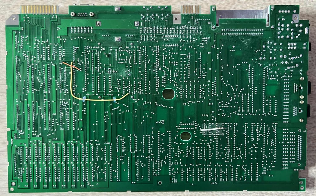
Below are some pictures of the mainboard after cleaning.
Visual inspection
The mainboard appears to be in good general condition after cleaning. I do not see any major damages, leaking capacitors or other oddities which could cause the machine not to work. Some other observations:
The power switch is a bit "stiff". It does feels to be working, but it is hard to switch the ON/OFF position.
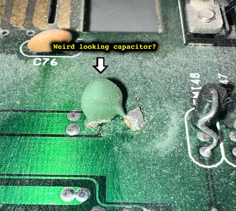
One of the small ceramic capacitors looks a bit twisted (see picture - taken before cleaning).
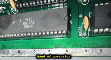
There are some signs of corrosion on the right hand side of the mainboard (front side). The corrosion appears to be in the ground plane (see picture).


In the table below the custom ICs are listed. As can be seen from the table below it is likely that this Commodore 128 was manufactured during the autumn of 1986.
Initial testing
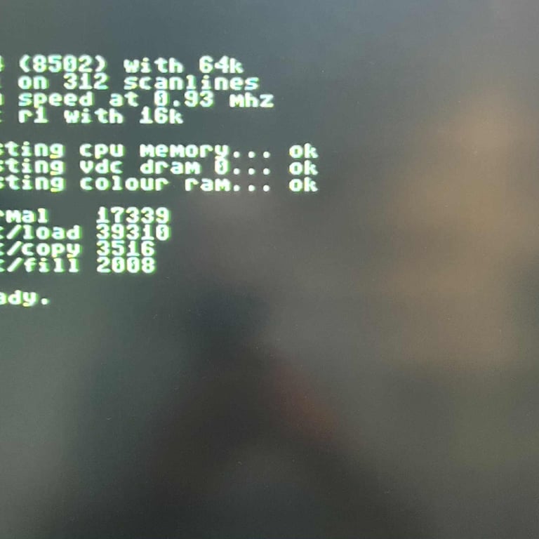
An initial test is performed on the mainboard. This is done with the purpose of checking the initial status of the mainboard - checking for any fault symptoms. In the table below the result are shown.
Below is a gallery of pictures showing some of the screens taken during initial testing (NOTE: the video quality is not optimal, but this is not caused by the machine - but by my poor TV). Click to enlarge the pictures.
Checking the voltages
For the Commodore 128 to work flawlessly all the different voltages need to present and within acceptable tolerances. In the table below all the measures voltages are listed (this list will also be updated after refurbishment). All the required voltages are present, and most are within tolerances. But the +5 VDC (from PSU) appears to be a bit low. Could this be caused by a dirty power switch? Or power connector?
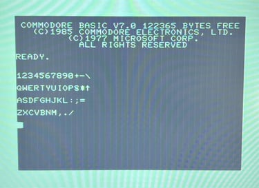
German character set (?)
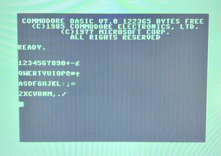
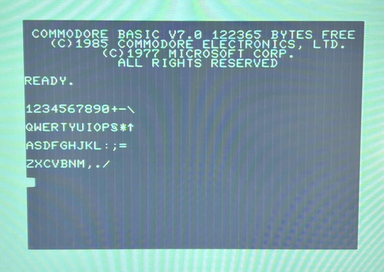
Both the Kernal- and the Character ROM are listed as "German". My first assumption was that this would mean that the keyboard would be mapped to a "QWERTZ" and not "QWERTY" character set. But that does not turn out to be the case - neither for the original Commodore charset or the DIN charset. See pictures below.

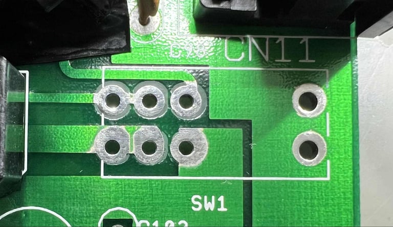
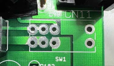
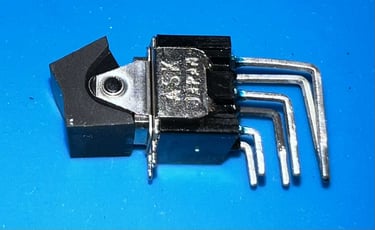
Refurbishing the power switch (SW1)
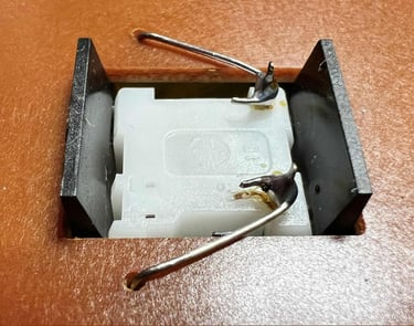
An old power switch can cause both toggling difficulties and voltage drop. This power switch is at least hard to toggle ON/OFF, and it is not unlikely that due to old age it introduces a voltage drop. To refurbish the power switch it needs to be desoldered first. When desoldering the switch it can be smart to use both a soldering iron and a desoldering gun at the same time. The power switch is desoldered from the mainboard without any damage to neither switch or PCB.
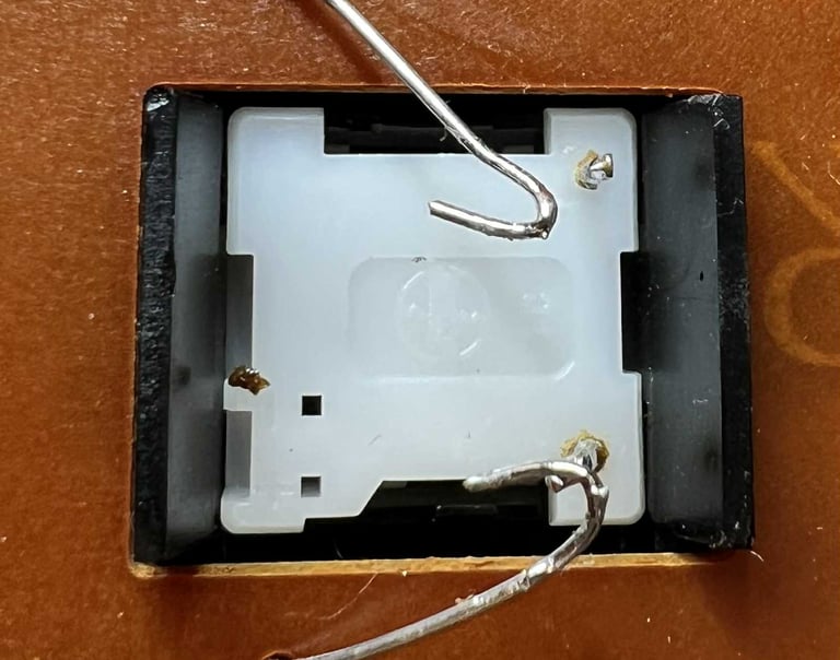
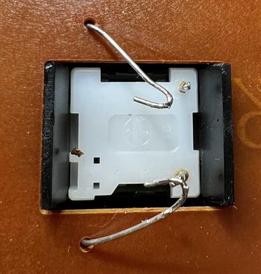
The switch is carefully pried open with a small thin flat screwdriver. Note that the switch must be opened (gently) on both sides.
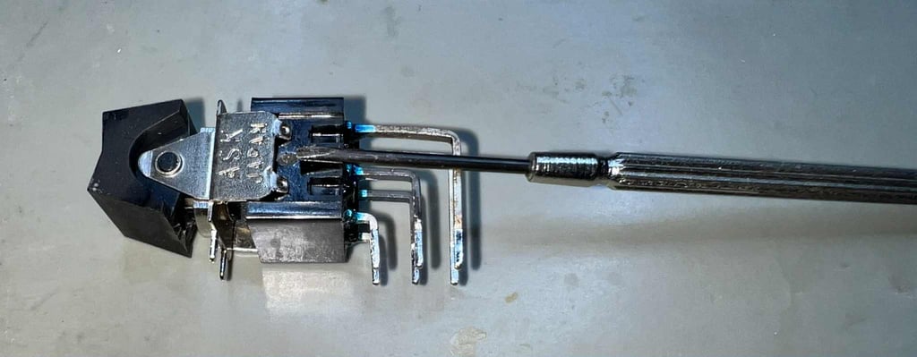

There are some dirt and oxidation on the metal plates inside the switch, but it was not as bad as I expected. I have seen much worse than this.
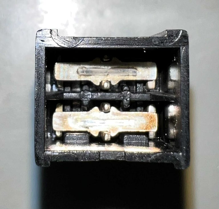

The metal plates, and the interior, is cleaned properly with a cocktail of contact cleaner and isopropanol. Finally, the power switch is re-assembled. Looks good as new. The rocking/toggling mechanism now works way better. After the refurbished switch is soldered back in on the mainboard, a new voltage measurement from the +5 VDC PSU rail is made (on the user port). There is only a slight improvement: 5.852 V (compared to 5.844 V before). So, unfortunately, cleaning the switch did not improve the voltage level - but it did improve the rocking/toggling mechansim.

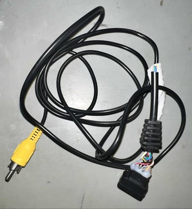
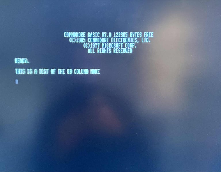
Testing the 80-column mode
The Commodore 128 can provide a 80-colum mode video picture. This can be done by pressing the "40/80 Display" key. I currently don´t have a proper RGBi cable, but it is possible to retrieve the monochome signal (pin #7) from the port and use this as a composite signal. A simple cable is made for this purpose. Below is the pinout for the RBGi connector, and a picture of the homebrew cable.

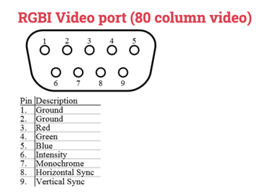

With the cable connected to the video display, and the 40/80 key enabled, the 80 column is monochrome displayed without any issues.

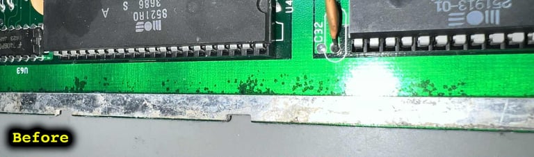
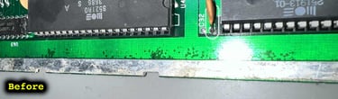
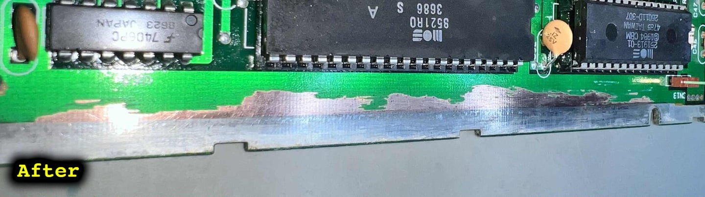
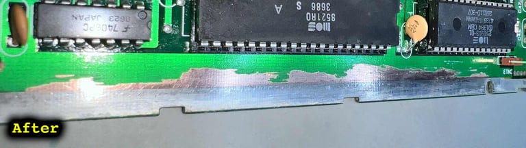
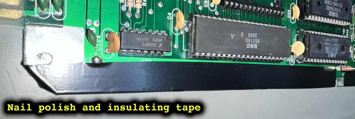
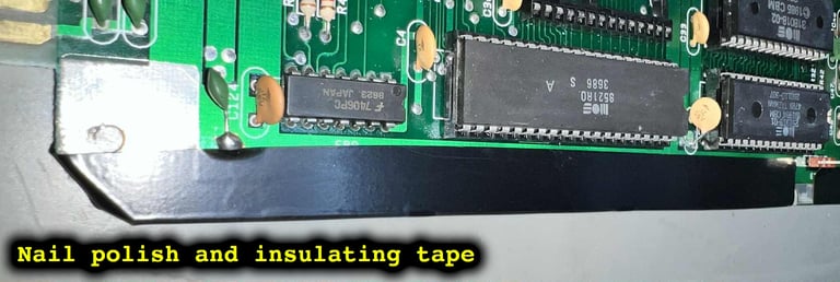
Removing the corrosion
There are some corrosion of the left hand side of the mainboard. This does not currently affect the machine in any way, but as a measure to prevent the corrosion from expanding the area is cleared. To to this a combination of a sharp pick tool, brass brush, vinegar and isopropanol is used. Finally, the area is covered with some transparent nail polish and some black insulating tape. See pictures below.
A very mysterious fault
During the refurbishment I notice that there is a FAULT (!). But not an easily catched and fixed unfortunately. The symptoms are as follows:
After several ON/OFF cycles (with about 5 seconds intervals) the machine sometimes produce a black screen or a boot screen without the flashing cursor.
A typical scenario could look like this powering ON/OFF ten times: 5 x OK normal boot up, 2 x BLACK screen, 3 x OK normal boot up.
What could cause such as fault? Since the fault is not permanent, and the machine seems to be working fine once it is booted OK, this is my hypothesis:
An issue with the reset circuitry (e.g. a bad capacitor)
Poor power switch
Poor power socket
A marginal CIA #1 since there are also the symptom of a non-cursor boot up screen
Poor power supply
A marginal glue logic chip
Checking the reset circuitry
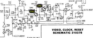
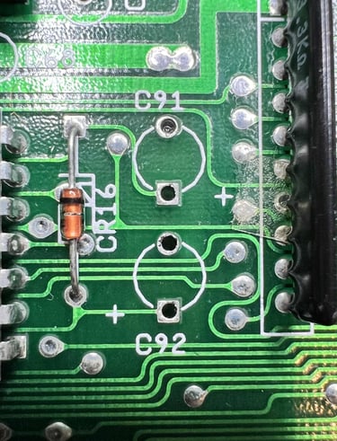
Checking with the oscilloscope the reset circuitry seems to be ok. When the machine is powered on, even when the machine produce a black screen, the reset circuitry seems to be working fine. The reset line is kept low for about a second (or slightly less) before raising to a high level. Nevertheless, there are two electrolytic capacitors (C91 and C92) which are part of the circuit which could impact the timing of the reset. See schematics below.
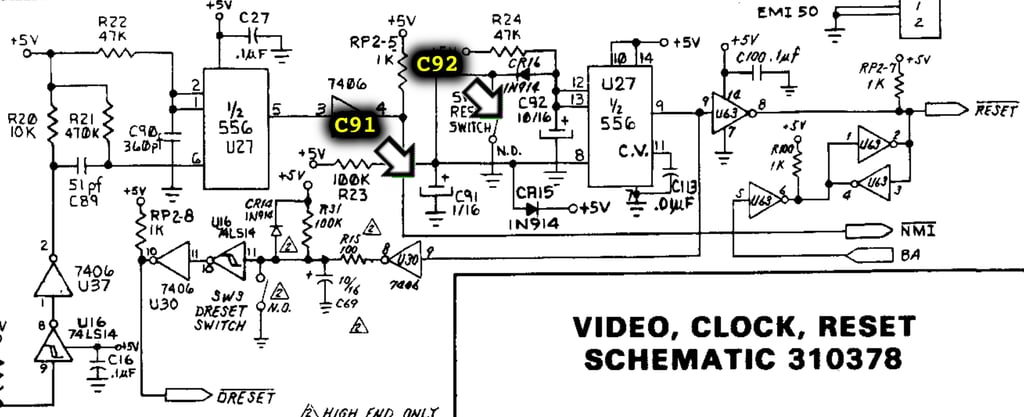
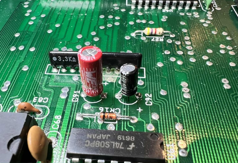
The two capacitors, C91 (1 uF / 50 V) and C92 (10 uF / 16 V), are desoldered without any damage to traces or pads. New quality capacitors are soldered in. See pictures below.

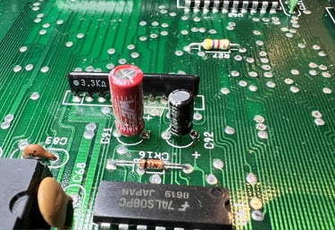
Did changing the electrolytic capacitors help? No... same issue. When power cycling the machine ON/OFF about 10 times the machine is producing a black screen about 8 out of 10 times.
Changing the external power supply
As previously mentioned during the "Checking the voltages" chapter the +5 VDC rail from the PSU appears a bit low. But this could very well be caused by the power supply itself. In the test setup an original Commodore 128 power supply is used. To see if there are any different a new modern PSU is used (made the renowned Ray Carlsen in the US).
And now something interesting happens. When power cycling the machine 10 times in a row, with about 2 seconds interval, the machine boots correctly each time. But... not so fast... after some more testing also when using the Ray Carlsen PSU the machine produce a black screen or a bootup screen without flashing cursor.
And as an interesting fact: when the Ray Carlsen PSU is used the measured voltage (+5VDC) at the user port is 4.756 V - 4.771 V. This is both when the machine produce a black screen and when the machine is working.
Changing the CIA #1 IC
Another clue is the symptom of the missing cursor. Could it be a marginal 6526 CIA #1 chip? A known good CIA IC is installed and the machine is tested again. On first 10 x test all of the power cycles works perfectly. On the second 10x power cycle the machine works 8 out of the 10 cycles. As a fact, when the original CIA chip is installed back, the attempt of power cycle 10x times shows a 10 out of 10 success rate.
Changing the CIA chip did not fix the problem, but it "felt like" improving the situation slightly. So what to make out of that? Well, I can´t say for sure, but it appears to me that the problem is either timing or power related in some way. When another IC (here: the CIA) is installed the timing and power characteristics is likely to change slightly. And as a result the behaviour of the machine is to change slightly.
Cleaning the power connector
The power connector is cleaned properly with contact cleaner, while the power cable is inserted/removed several times to allow for any oxidation to disappear. But, even after cleaning the power socket several times the result is still the same. The machine works most of the times, but from time to time it has problem starting.
Current conclusion
I really can not find the fault here. I do not want to start changing components chasing red herrings. When the machine boot up ok the machine works fine as I can see it. It does not crash or show any signs of malfunction. It is just on power-on that the machine sometimes fails to start.
My gut feeling is that there is one component which is marginal, and as time go by will fail completely. But to "catch" this component at this moment is very hard. It is way more efficient, and way less damaging to the machine, to wait until it dies eventually and then try to repair it.
Another repair attempt
After storing the machine for a couple of weeks it is tested again. And now the fault is more "permanent". In the sense that when it is powered on the boot screen is presented, but no flashing cursor. Now that the fault appear to more solid, it give hope of finding the fault. But during disassembly something happens:
When the top cover is removed the machine is powered on: same fault. No flashing cursor.
When the metal RF-shield is removed the machine is powered on: No fault. Machine boots with flashing cursor.
It still can be a marginal IC, but I think this can be caused by a poor socket or a marginal trace.
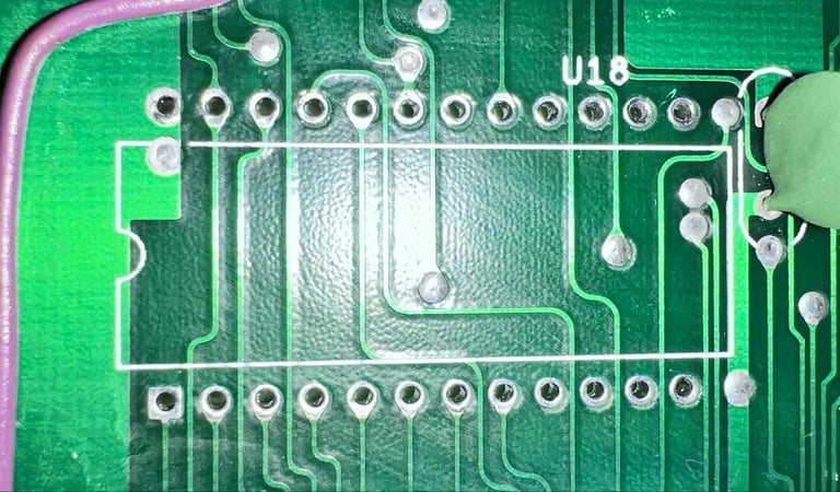
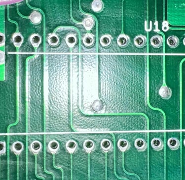
Replacing the U18 socket
It can be a coincidence, but when I manage to "catch" the fault situation (no flashing cursor) and then barely press the U18 ROM the cursor springs to life. This could point to a poor socket, and the U18 IC is installed in a single wipe socket.
The old socket is removed and a new quality 24 pin dual-wipe socket is installed.
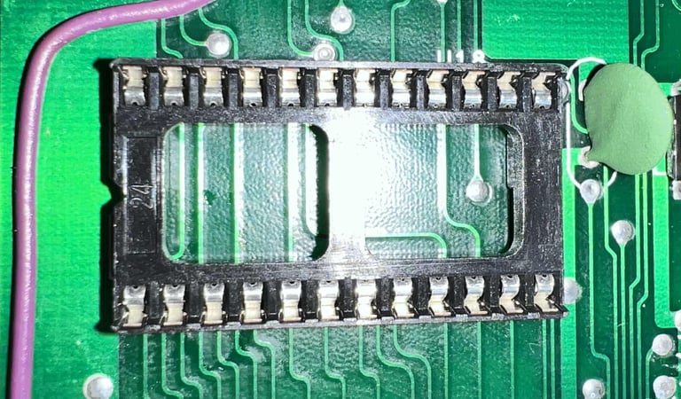
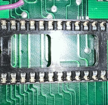
Result: Short story: no change. Same fault. Long story: after replacing the socket it does appear to be working fine. I can reboot the machine again and again without any problem. But when trying to re-assemble the machine (and RF-shield) the fault is back after the 5 or 6 th power cycle.
Resoldering some solder points in the U18 area
It appear to be something related to the area surrounding the U18 IC. This can be a red herring, but the moment the slightest pressure is put on the U18 are the machine boots. There are no socketed ICs in this area, but several of the ICs are have their solder points resoldered.
Result: No change. Same fault.
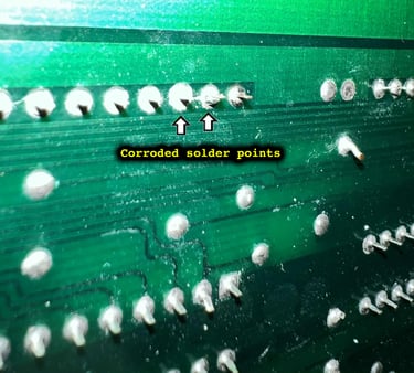
Resoldering some solder points in the U4 area
Continuing the process of resoldering solder points I notice something: the solder points for pin 22 and 23 (U4 CIA#2) appear very crusty . So crusty that they will not reflow solder until they are scraped and cleaned. Feels like I am clinging to a straw here, but the CIAs are vital for the cursor to work. And both the pin 22 and 23 are important signals as they represent R/W and CS respectively. It is hard to see from the picture below, but pin 22 and 23 are quite corroded.

Result: I am holding my breath here. So far the machine boots every time. And now the machine is completely assembled. I will leave it like this for 3-4 days and see if it still works.
I would say this is a success! After almost a week the machine still boots fine without any issues!
Testing
NOTE #1: Testing is done when the machine is booted OK. As previously mentioned there is a fault preventing the machine from booting from time to time.
NOTE #2: The colours on the test pictures are wrong. This is due to an issue with the TV and not the machine. The pictures does show the functionality nevertheless.
Testing a C128 is like testing three machines: C64, C128 and CP/M (Z80). Most of the testing is based on the C64 mode since this is where most of the test tools are available, but also since these chips are used for the C128 as well.
Testing is done through three main stages:
Testing the basic functionality and chips (C64/C128 mode)
Testing by using the machine playing demos, games etc. accessed by both floppy and datasette to verify correct operation (C64/C128)
Testing C128 and Z80 specific features: 80 column mode (VDC chip) and CP/M mode
Basic functionality and chips
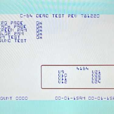
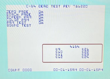
First test is done using the Dead Test Cartridge. This test doesn´t test all the functionality of the Commodore 64/Commodore 128, but it does test the basic functionality of the major chips such as the CIA #1/2, CPU, VIC-II, PLA, RAM and SID. As the picture shows below the test is passed.

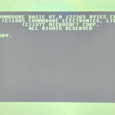
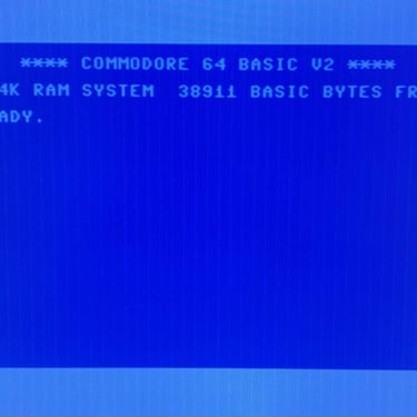
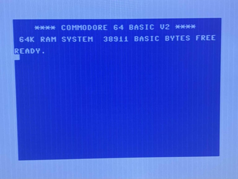
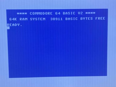
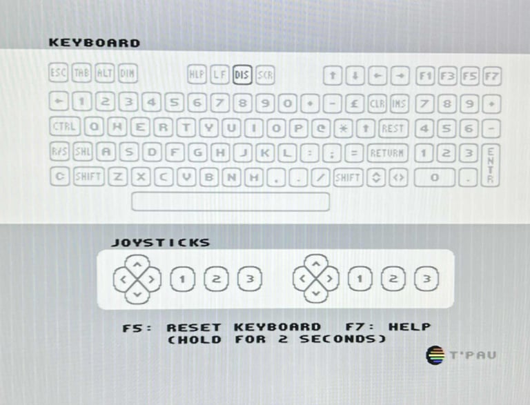
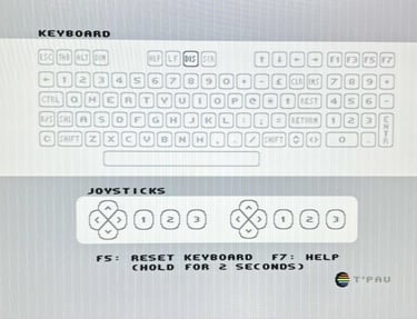
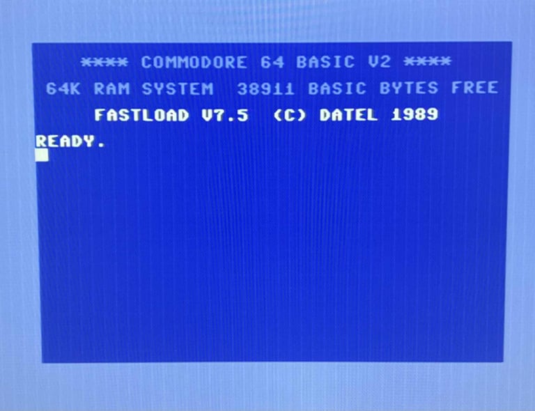
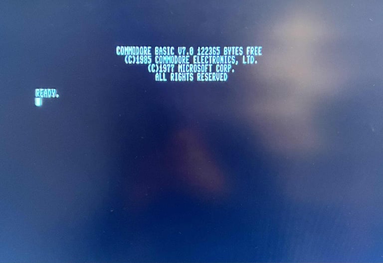
Next test is to power the Commodore 64/Commodore 128 to the boot up screen and also check the keyboard to make sure all keys works as they should. The test is passed; all keys works and 38911/122365 BASIC Bytes Free. Note that the 40/80 column display is disabled in the key test. The 40/80 column mode will be tested separately.
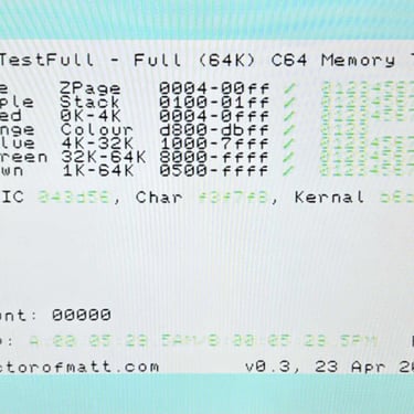
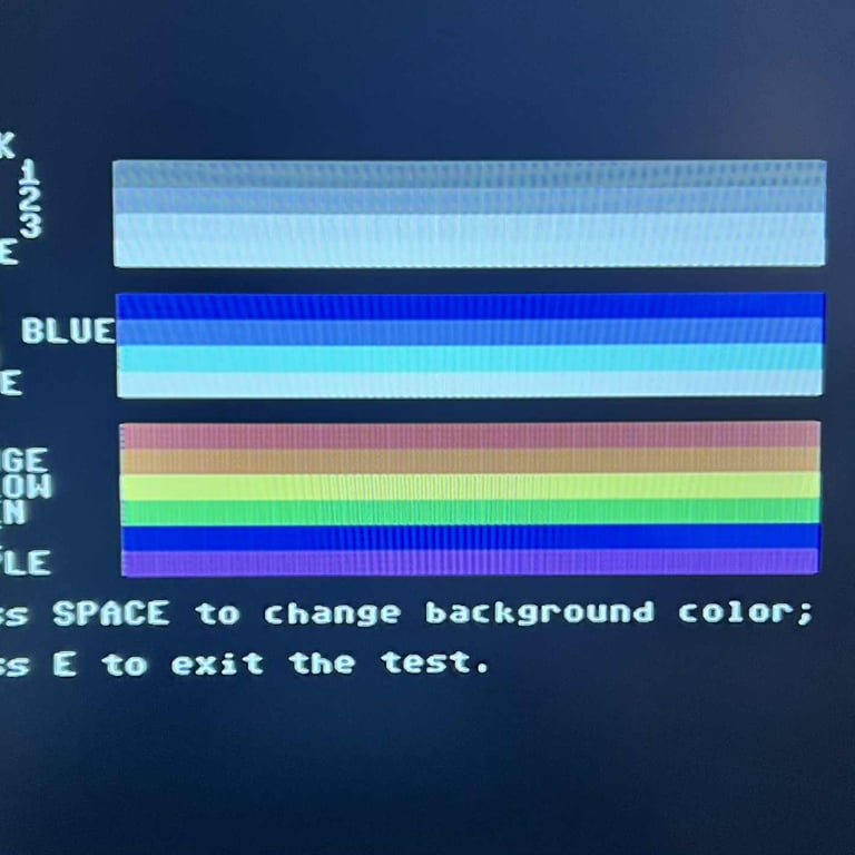
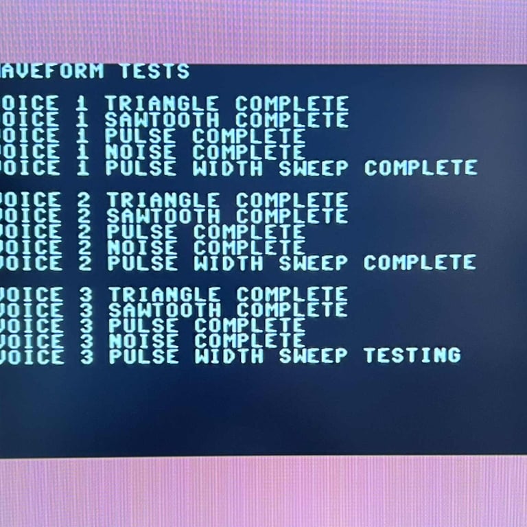
The basic functions of the VIC-IIe, SID and RAM is tested with 64 Doctor and Commodore 64 SID tester. Note that this is to be considered as basic functionality - more advanced (?) functionality such as sprite handling / collision detection / advanced audio will be tested later. But the basic tests pass without any detected faults (click to enlarge).
Last basic check before moving to more extensive testing is checking the cartridge. This is done by using the Action Replay cartridge. Result is that the test is passed.


Extended testing
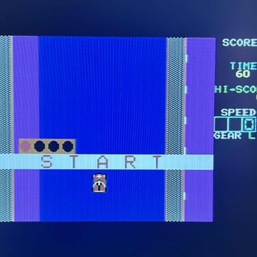
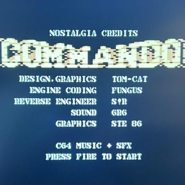
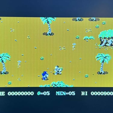
Knowing that the basic functionality of the machine works I continue the testing by using the Commodore 128 for normal operations; playing some games, watching demos, floppy and using a cartridge. I can not find any issues with this machine. I also pay special attention to the video to make sure that there are no glitches in the graphics - I can´t see any abnormalities. Below is a gallery with pictures from the testing.


80-column mode (VDC) and CPM/M
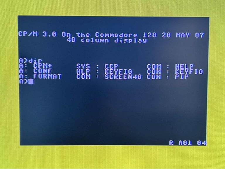
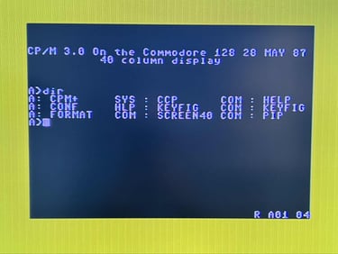
The Commodore 128 is capable of producing a 80-colum mode (in colours) using the MOS 8563R9 VDC chip. I do not have a proper monitor to test this, but the custom made monochrome cable described in earlier chapter is used. To activate the 80-column mode the "40/80 DISPLAY" key is pressed. This will disable the normal screen (making it secondary) and switch to 80-column mode on the RGBI-port. As the picture below shows the RGBI output (in monochrome) is present and working.

Final result
"A picture worth a thousand words"
Below is a collection of the final result from the refurbishment of this Commodore 128. Hope you like it! Click to enlarge!

"Are you keeping up with the Commodore? 'Cause the Commodore is keepin up with you!"
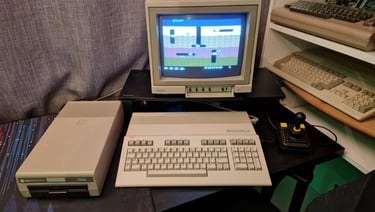
Below are some pictures of the Commodore 128 back at the customer´s home!
