
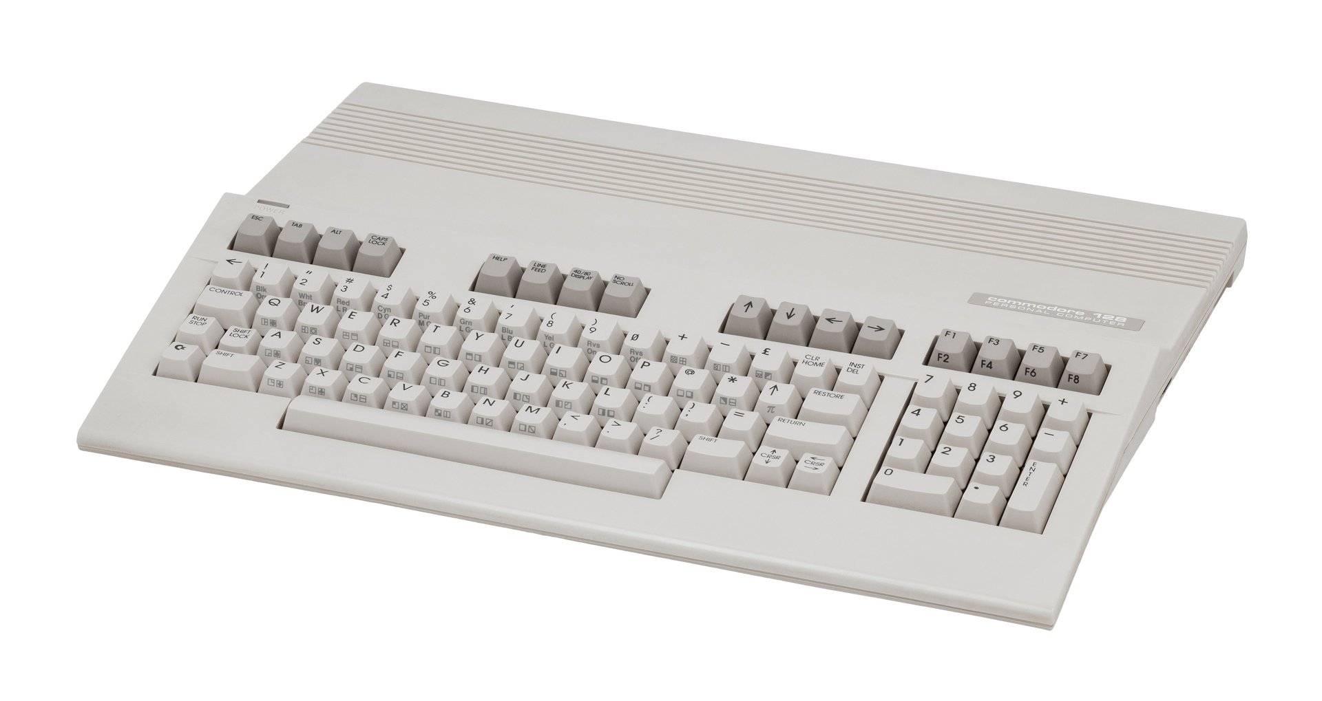
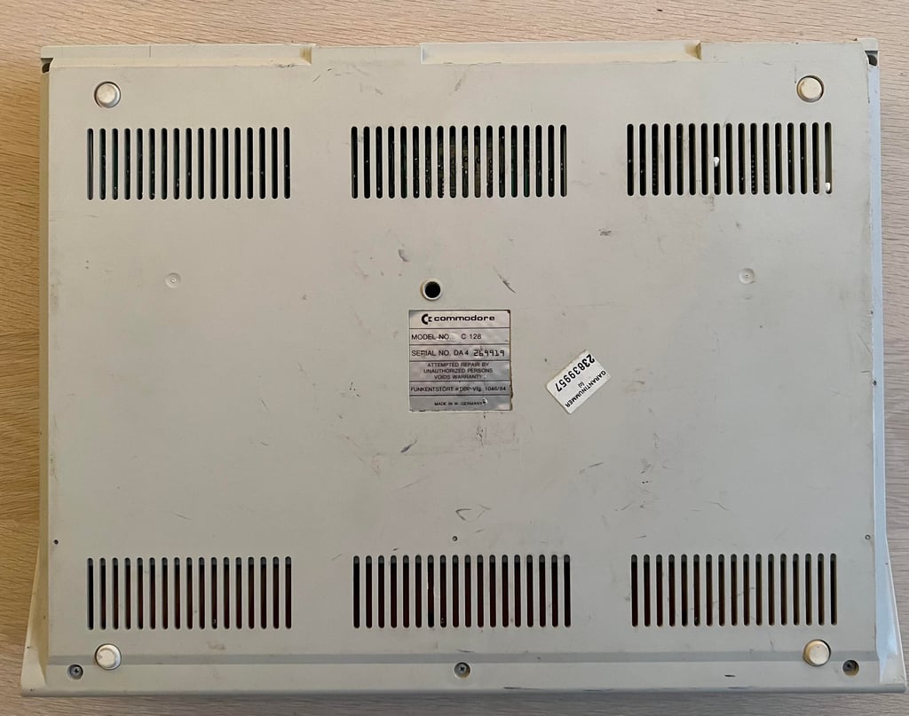
C128 [PAL]
Ser. No. 269919
Artwork 310381
(REV 7)
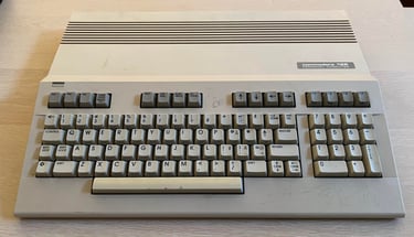
Starting point
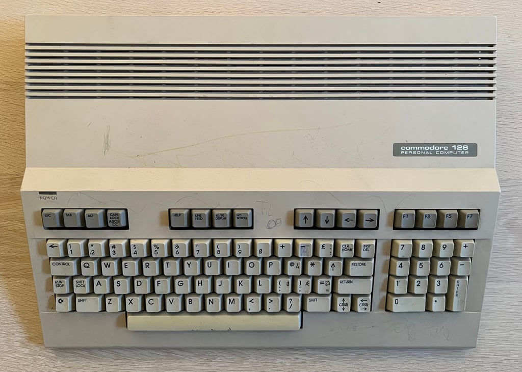
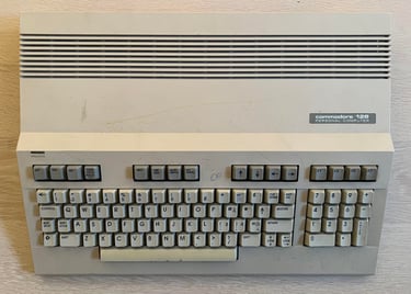
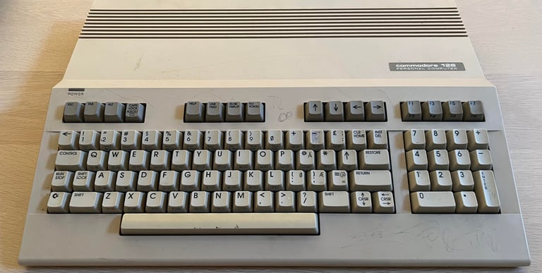
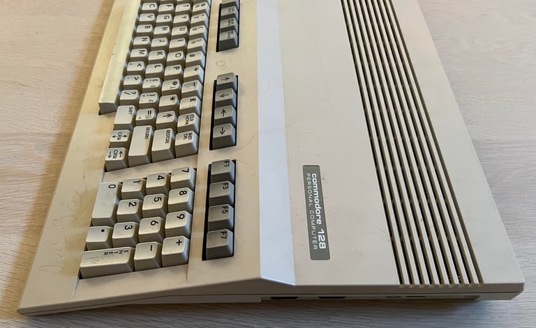
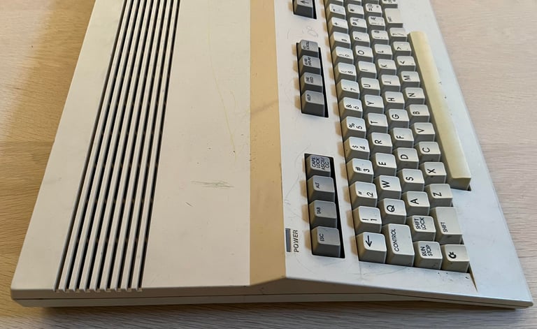
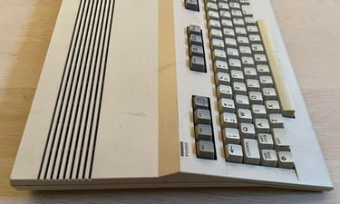
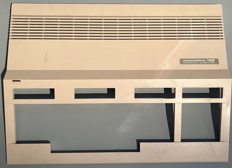
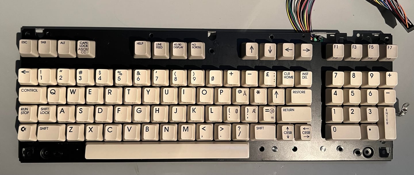
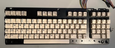
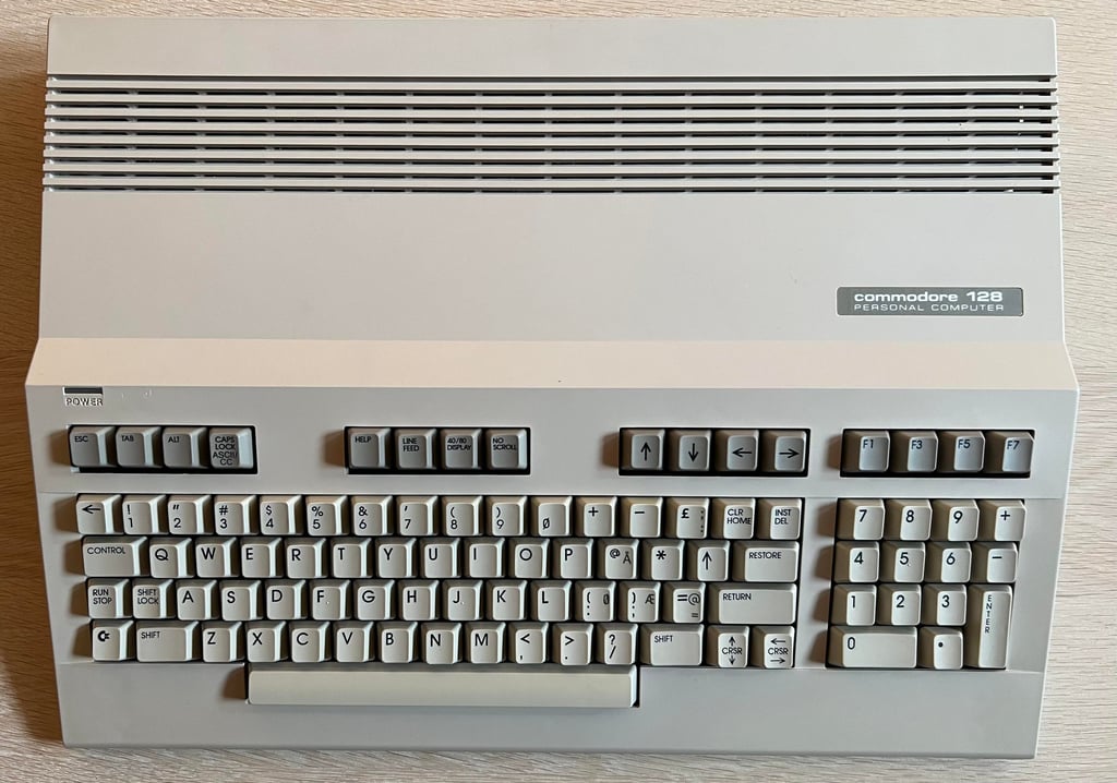
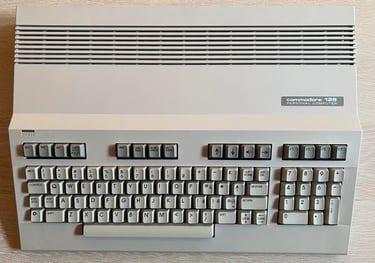
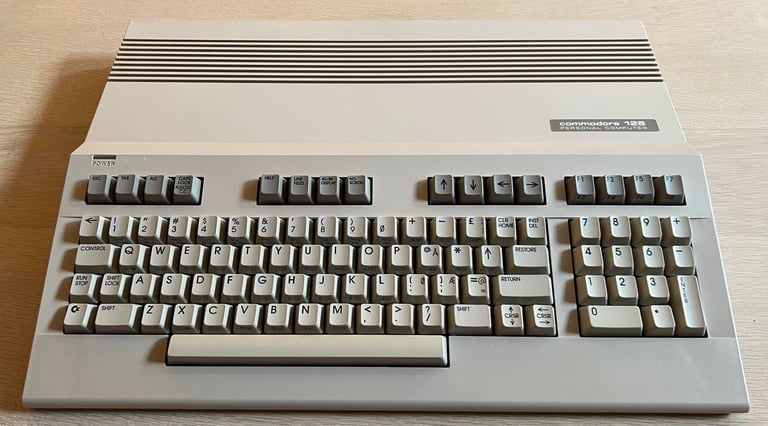
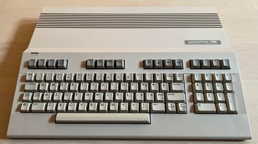
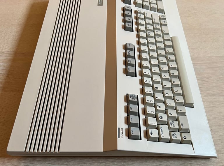
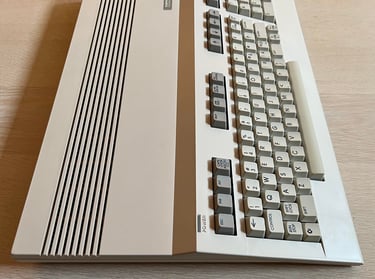
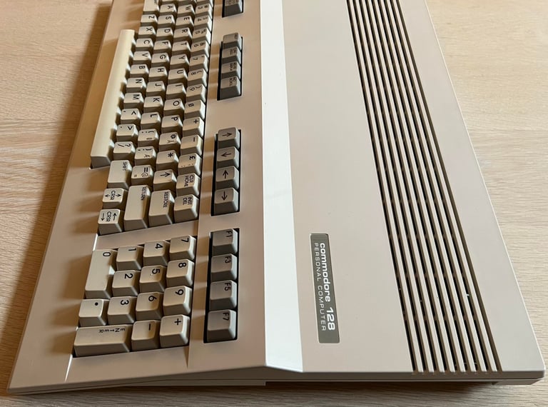
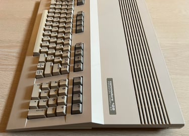
From the outside this flat C128 does not have the best looking appearance. The top cover, and even some of the keys, is full of scribbles. There is also some scratches on the cover. There is a Norwegian keyboard layout, but it seems like the printing of the Norwegian characters "Æ", "Ø", "Å" (and also the "@") is more worn compared to all the other keys. I would guess this is due to different manufacturing methods.
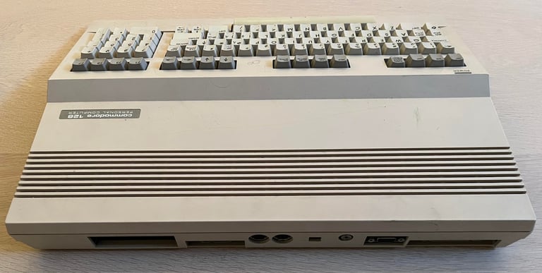
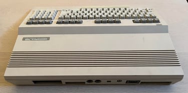
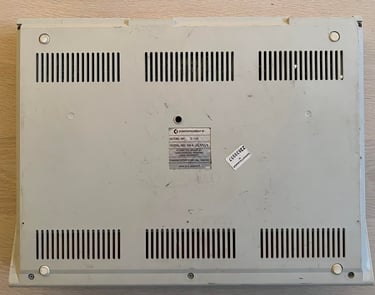
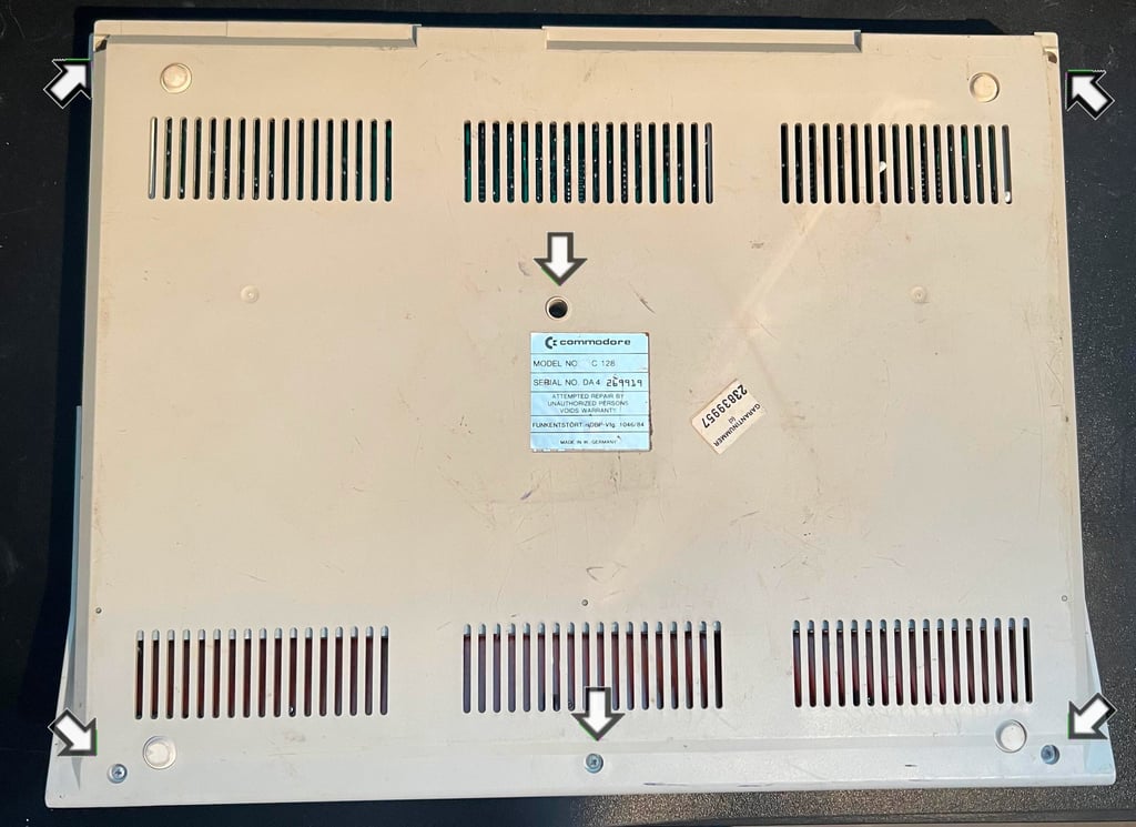
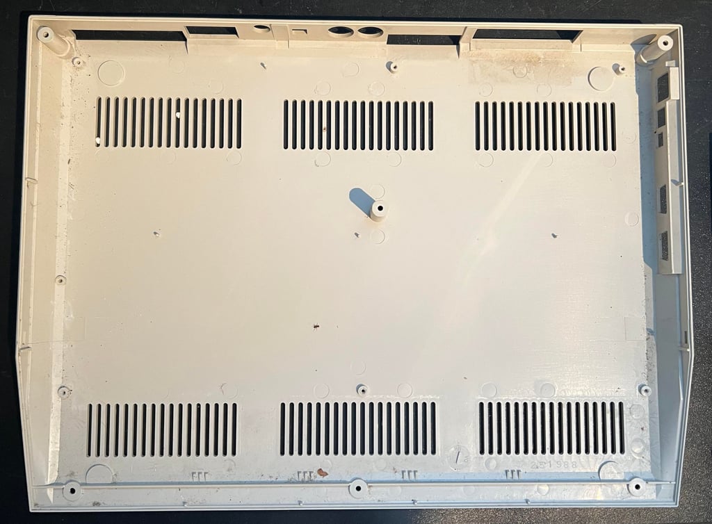
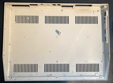
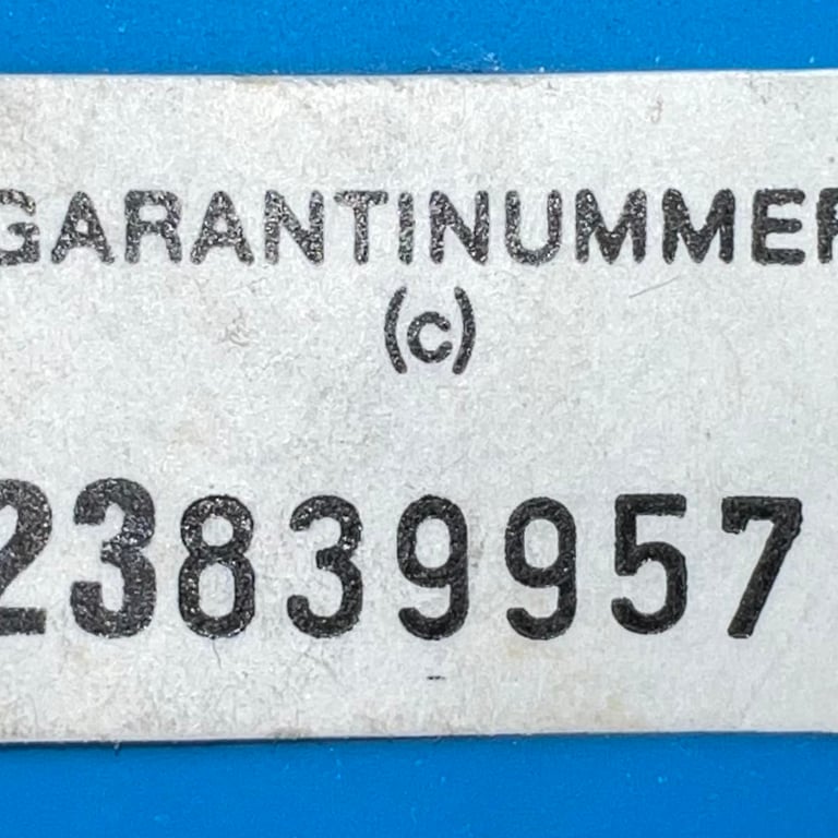
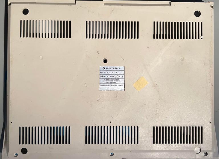
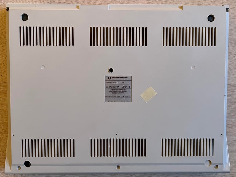
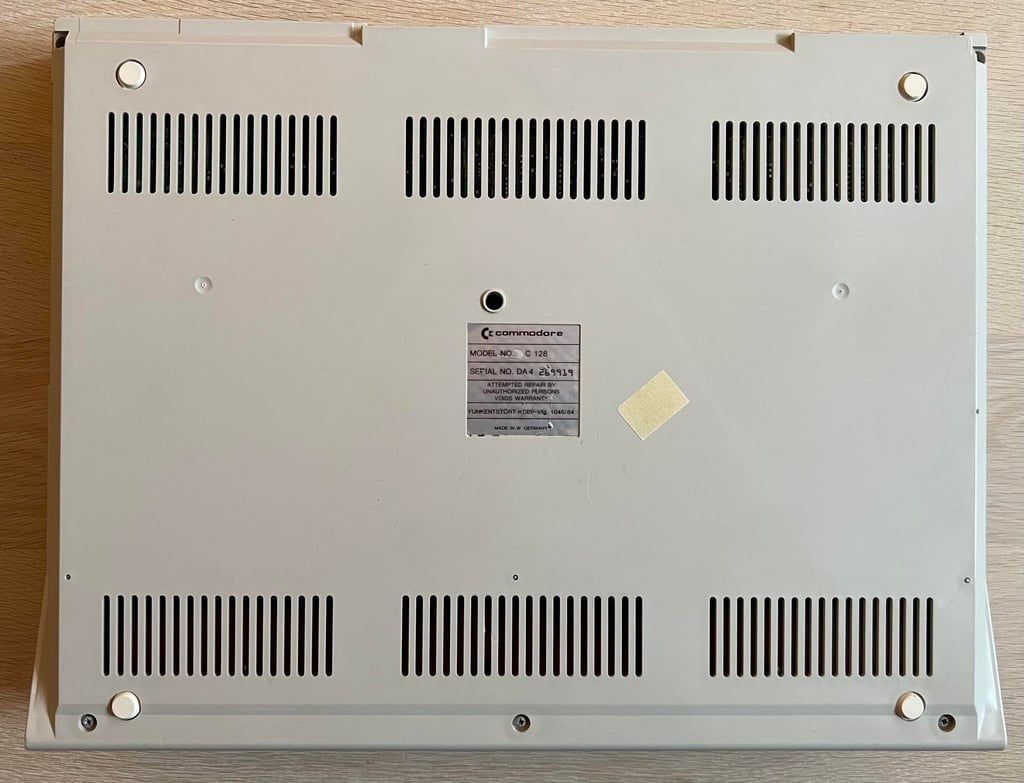
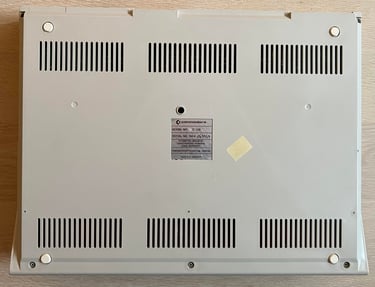
On the bottom cover the situation is quite the same as the front cover, except that there are no scribbles. A lot of marks and scratches. Also there is a Norwegian marking saying "GARANTINUMMER" which translates to "WARRANTY NUMBER" in English.
I do not know in advance if this machine works or not...

Refurbishment plan
The refurbishment plan for this flat C128 (several of them in parallell):
- Refurbish the casing (cleaning, repairing and retrobrighting)
- Refurbish the keyboard (cleaning, reviving the plungers and maybe retrobrighting)
- Refurbish main board (cleaning, checking, repairing, replacing capacitors and voltage regulators, adding heat sinks etc.)
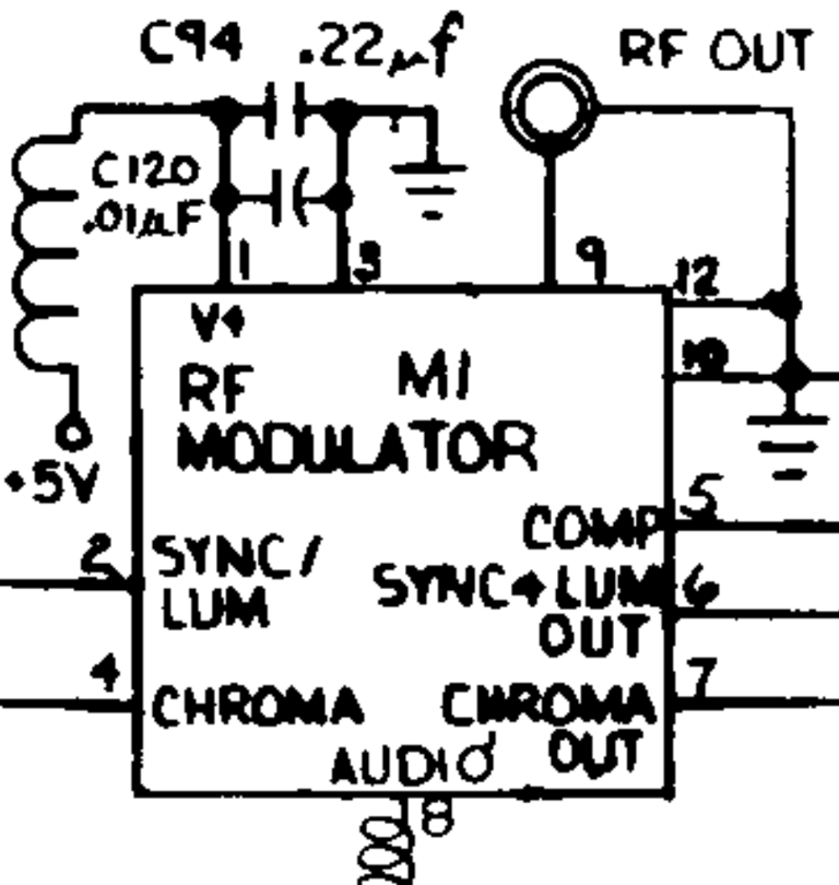
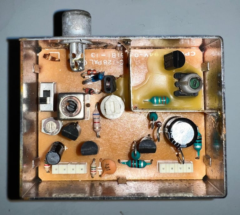
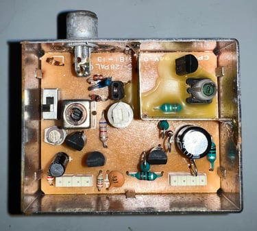
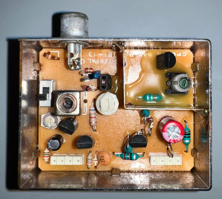
- Recap RF-modulator
- Verify operation by testing
The plan can be updated during the refurbishment process. Sometimes I discover areas that needs special attention.
Opens it up...
Opening a C128 is not difficult, but it is wise to be somewhat careful to not break any of the brittle plastic. First action is to remove the six screws from the bottom cover.

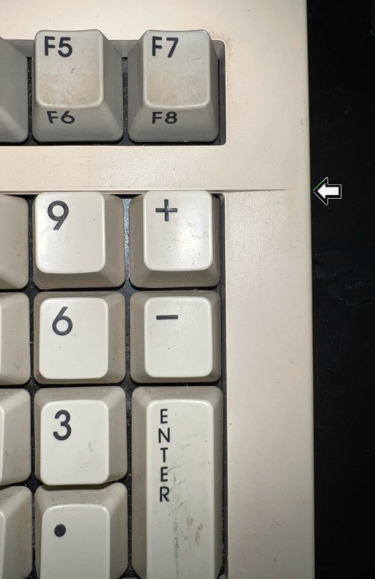
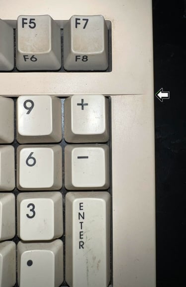
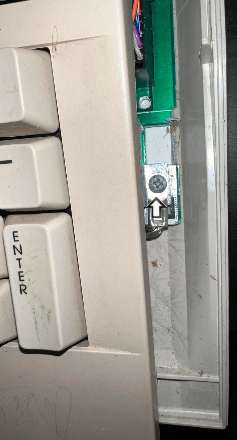
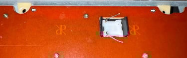
Now comes the careful part. On each side of the top cover there is a small plastic clip which can easily break if not careful. To find the position of this plastic clip follow the thin embossed line just above the numeric keypad. See picture below for where this embossed line is located.
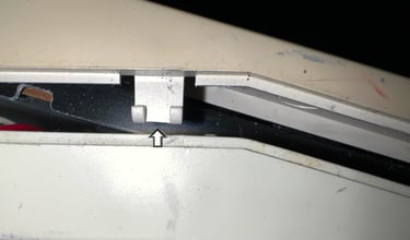
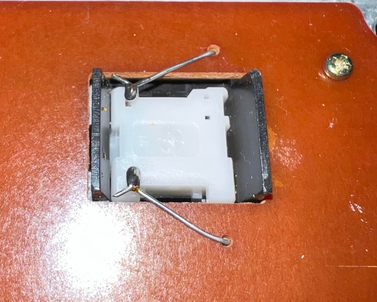
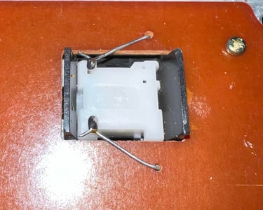
With a thin flat screwdriver the clip is gently pushed inwards while the top- and bottom cover are wiggled loose. This is not super easy, so it is wise to not rush this. Below is a picture of the small plastic clip when loose.

The top cover is slid slightly to the side so that the ground screw is exposed. This screw is removed so that the top cover can be lifted further.

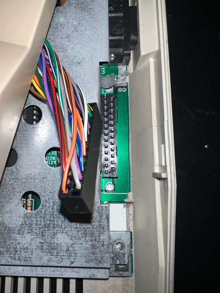
Next, the keyboard connector is removed. This is quite "stuck" and require the use of a thin small screwdriver to carefully pry it open. I have seen this on other C128 before so I think this is quite normal.

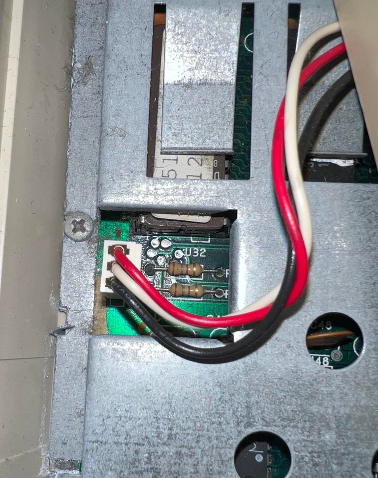
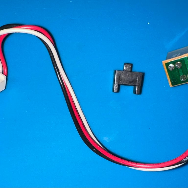
Finally, the LED connector is removed and the top cover is free.

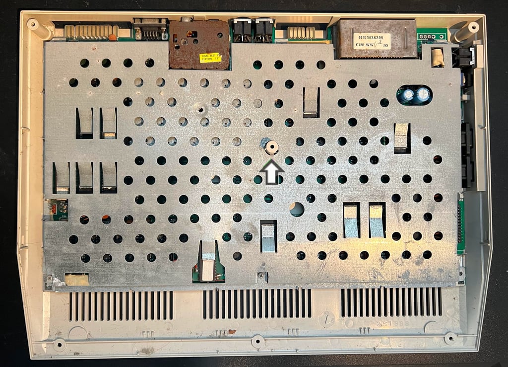
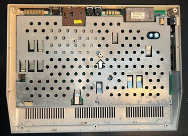
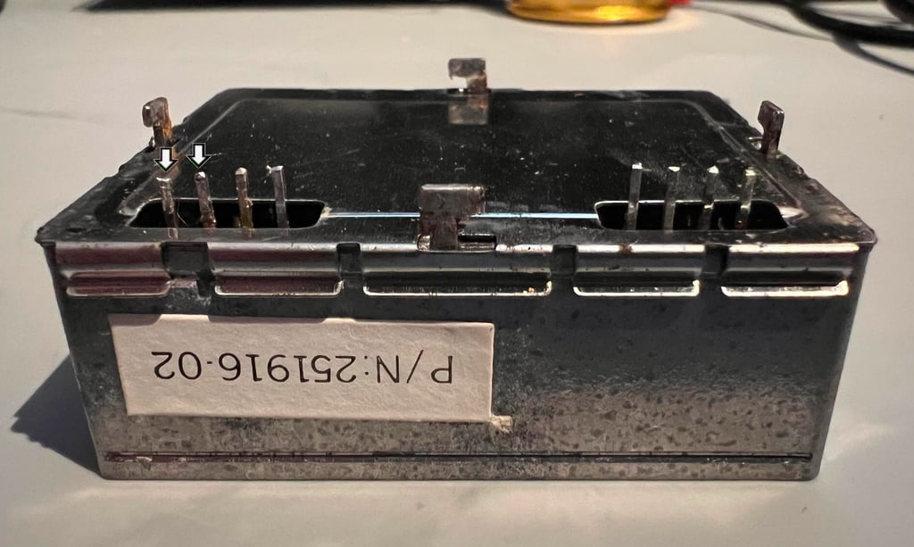
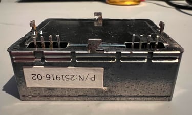
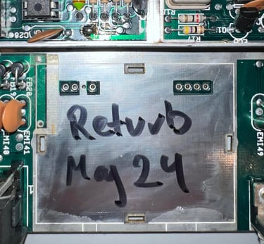
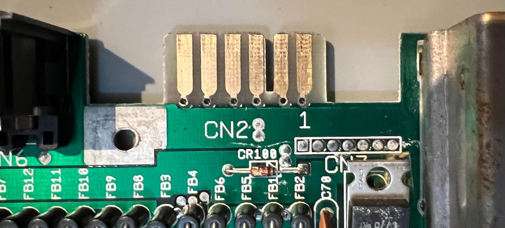
The RF-shield is now revealed. There are no signs of corrosion on the RF-shield, some sign of corrosion on the cartridge port and lots of corrosion on the RF-modulator. Nevertheless, this should not affect the machine in any significant way. Also, there is plenty of dust inside here, but that is expected after all these years. To remove the RF-shield all the six screws are removed, all the eight metal tabs are bent in a straight position and the plastic pole in the middle is locked to the shield with some tabs (see arrow).
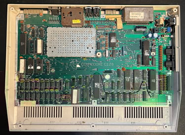
With the RF shield out of the way the mainboard is revealed in all its glory! There is a LOT of dust and grease inside and dried out cooling paste - but it otherwise looks to be in good condition.

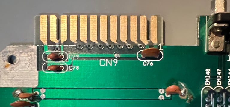
Eventually the small metal tabs in the joystick port / keyboard connector area are straightened, and the mainboard is lifted out of the bottom cover.
Exterior casing
Both the top- and bottom cover is a sad spectacle. They are full of scribbles made from what looks like tools such as a ball point pens and crayons (?). There are also some scratches, but I think they are not too bad. Before cleaning the LED, rubber feets and "Garantinummer" (eng: warranty number) sticker are removed. Removing the LED is not difficult, but requires a bit of careful fiddling loosening the small black plastic clip. The "Garantinummer" is gently removed with some hot air from a hair dryer while prying it off with a thing spudger. The reason for removing the rubber feets is that these can be damaged (they become "sticky") if I decide that the covers needs chemical retrobrighting. In the picture gallery below all of these parts are shown (click to enlarge).
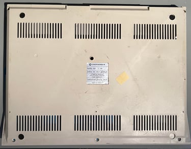
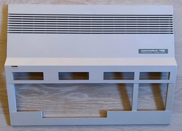
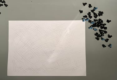
Below is a picture of the top- and bottom cover before cleaning and retrobrighting. Hopefully most of the scribbles will be possible to remove.

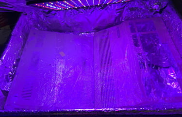
Both top- and bottom cover are soaked in mild soap water for about 24 hours. This removes most of the fat and grease. The remaining stains are removed with isopropanol on a Q-tip. The covers are not very yellowed, but I decide to retrobright these anyway. 12 % hydroperoxide cream is applied regularly to the covers (wrapped in cling film) and exposed to UV-light for about 12 hours. See picture below.

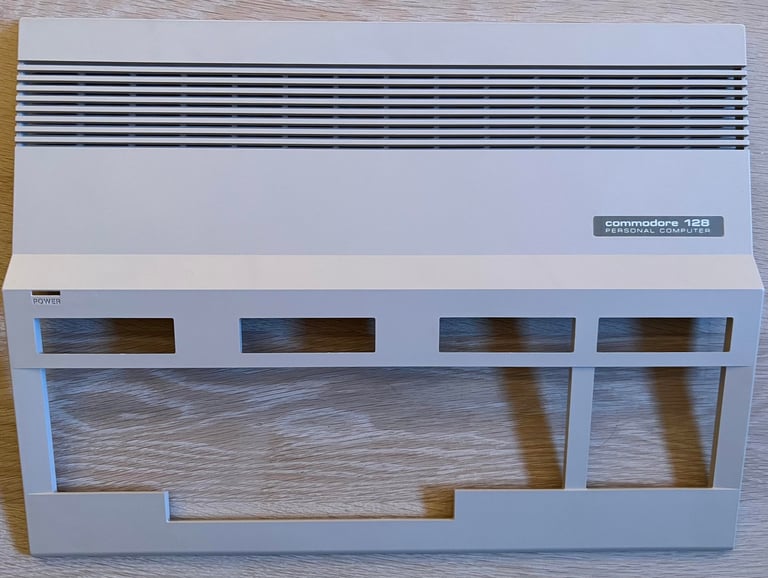
The result av this thorough cleaning and retrobrighting is very good I think. There are some few scratches, but they are not easy to detect I think. I am very pleased with the result.

Keyboard
The keyboard needs to be disassembled from the top cover. This is done by first removing the six screws from the backside of the keyboard. See arrows in the picture below.
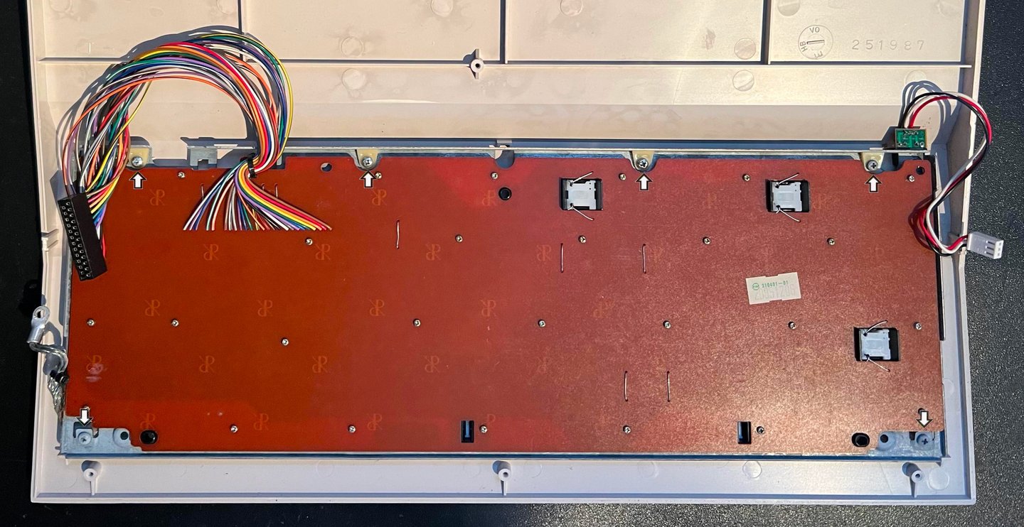

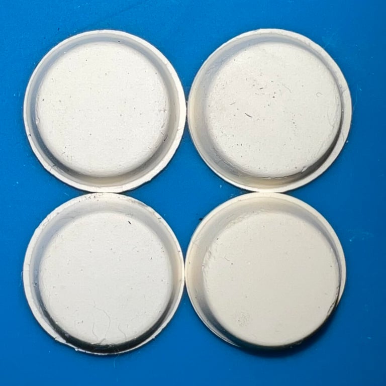
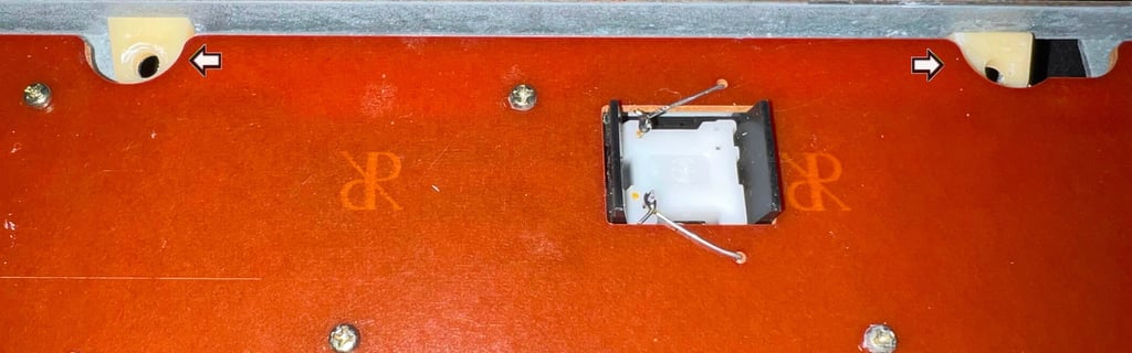
Note that there are four plastic spacers beneath the top screws. It is a good idea to lift these off the metal top cover before cleaning to avoid loosing them later. In the picture two of these plastic spacers are shown.
Next, the wires connected to the SHIFT-LOCK, CAPSLOCK ASCII/CC and 40/80 DISPLAY keys are desoldered. The wires are twisted around the small metal pins on these keys. While using the soldering iron on the wires the wires are lifted from the pins with a pair of tweezers.
The keys are very dirty and some of them have scribbles. To remove the keys for cleaning a key puller is used. This is the most gentle way to remove the keys - reducing the risk of damaging plungers and/or keycaps. Note that there are two small additional springs beneath the spacebar which is wise to keep separately. Also, one some of the keys (such as the enter key) there is a U-shaped metal bracket. NOTE: to remove the special keys such as the SHIFT-LOCK push firmly from the backside of the keyboard towards the front.
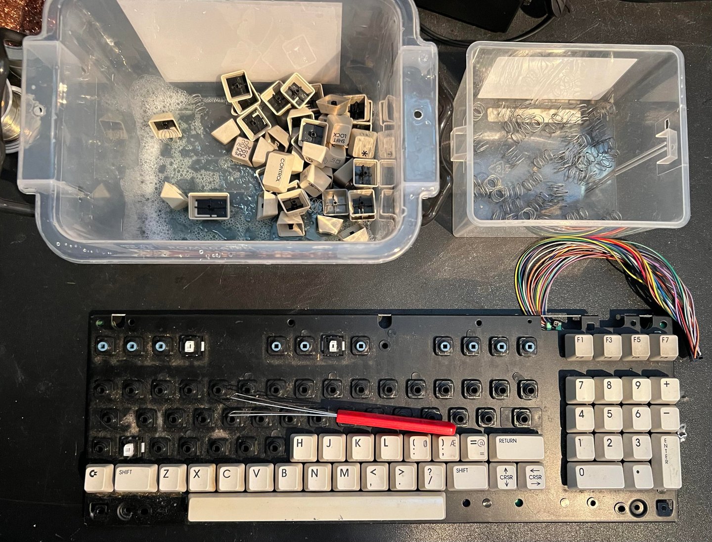
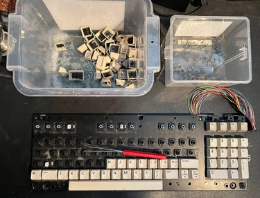
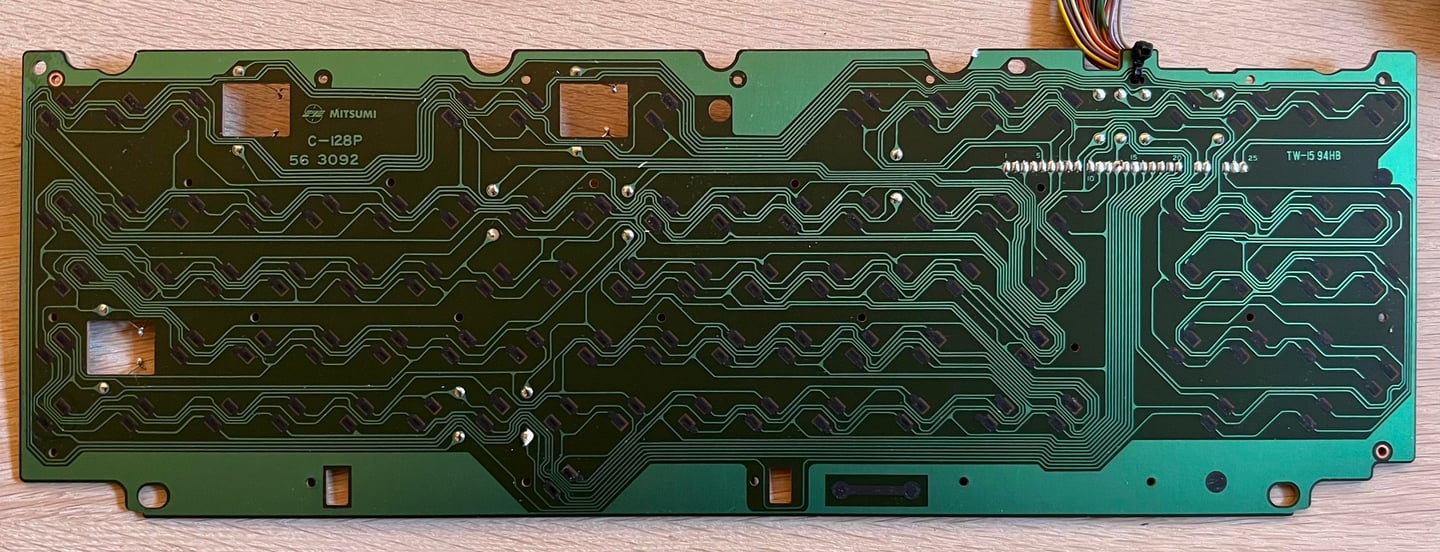
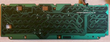
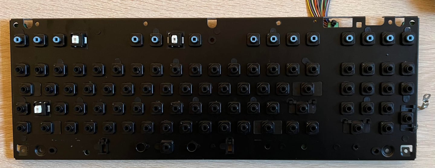
All the keys are placed in a plastic container filled with mild soap water for about 48 hours. Next, the 27 small screws at the backside of the keyboard are removed. This will reveal the PCB which are cleaned with some battery water (distilled water). As can be seen in the picture below the keyboard PCB is a MITSUMI C-128P 56 3092.
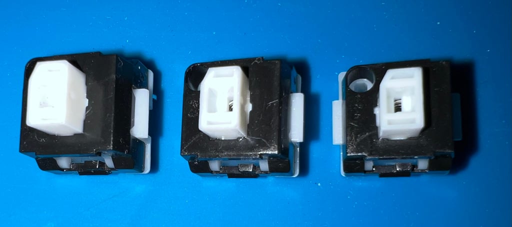
With the keyboard PCB out of the way the plungers are exposed. Note that the top row have plungers which are of a different colour. I am not really sure why that is the case as the form factor appears identical otherwise.

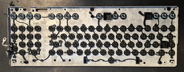
It is common that old Commodore 64/128 keyboards requires the keys to be pushed very hard, or hammered several times, in order to generate a key response. This is often due to either dirt on the carbon pads on the PCB - or that there are fat and grease on the conductive rubber on the plungers. To revive the conductive rubber the plungers are carefully rubbed over a clean sheet of paper.

Each of the specialized keys are inspected and the exterior is cleaned. At this stage they are not opened for cleaning inside - I think it is possible to open these the same way as the SHIFT-LOCK key on the Commodore 64, but they appear to work as they should.

The metal plunger holder is cleaned properly with mild soap water. This was full of old dirt, dust and grease and requires thorough cleaning. Eventually all the plungers are put back in the holder and the PCB re-attached. The end result looks very good - almost like new (?)

Mainboard
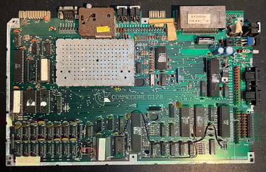
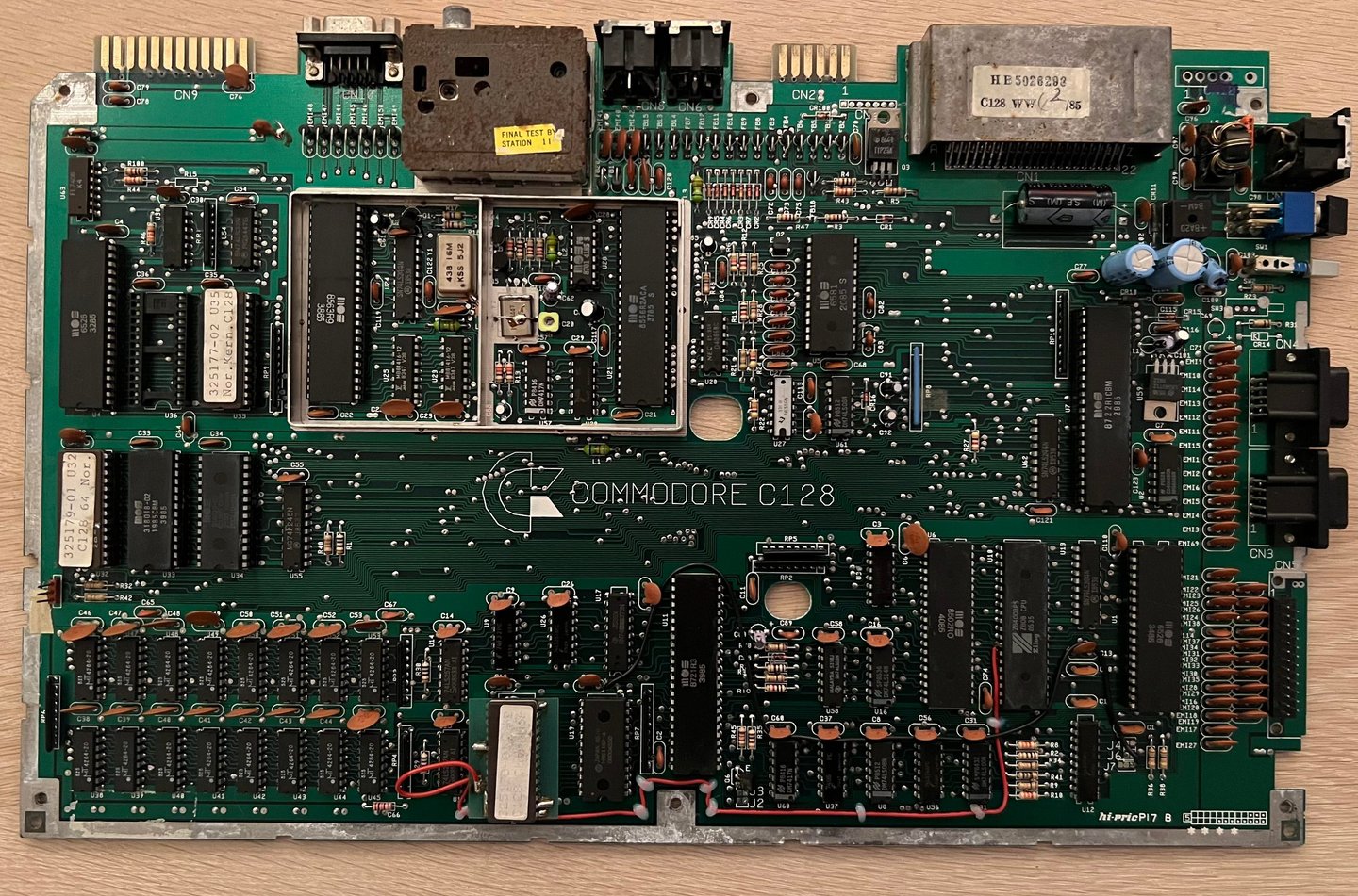
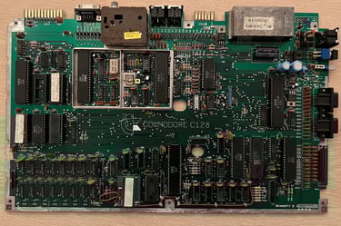
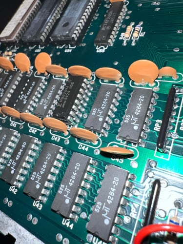
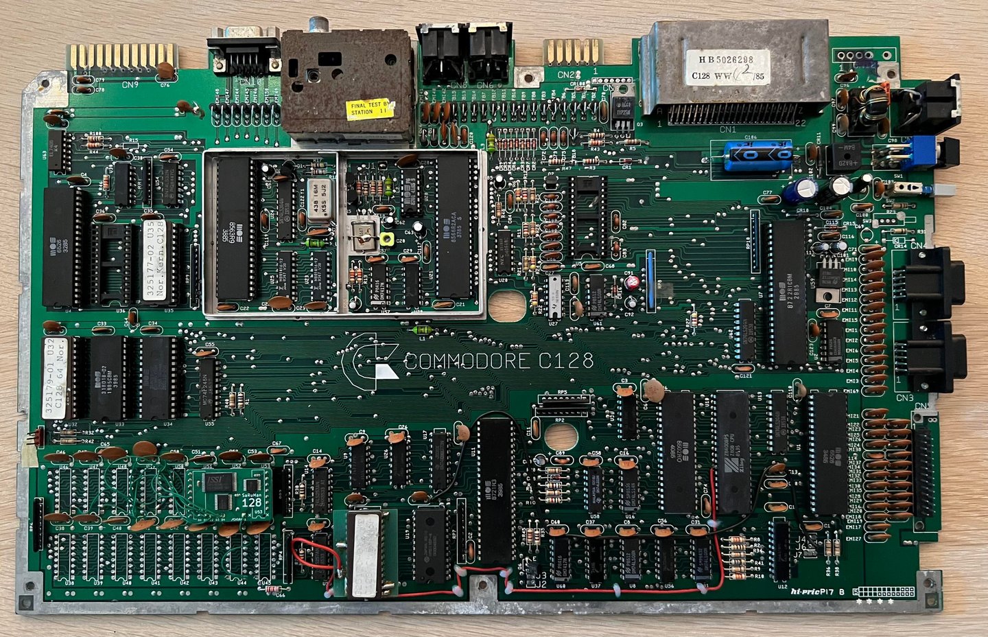
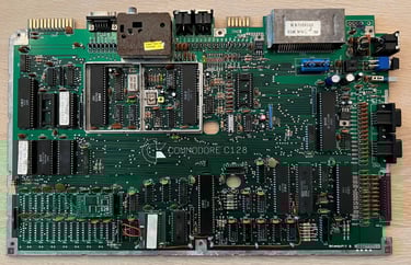
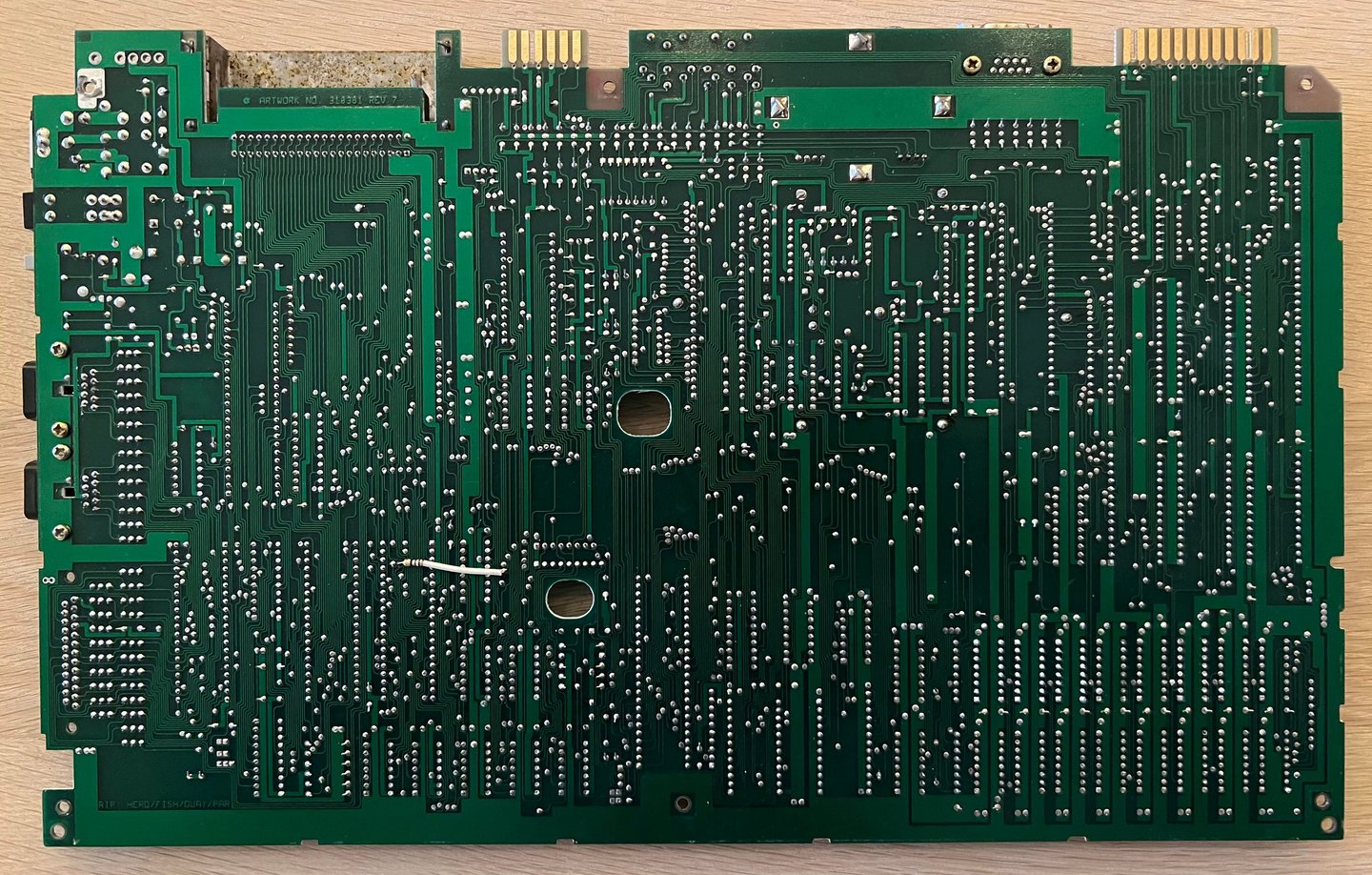
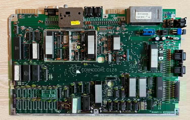
This is an Artwork 310381 (Rev 7) mainboard. Below are a pictures of the mainboard before refurbish.

Visual inspection
Before testing the mainboard a visual inspection is carried out with the following findings:
The top half of the mainboard (near the row of ports) is very dirty. Not so easy to see in the picture, but there is a thick layer of fat/grease/dust.
The top lid of the RF-modulator is rusted. There is also some rust on the rest of the metal can, but it is not very severe.
Some corrosion on the metal lid on the cartridge port, but should not affect the functionality in any way
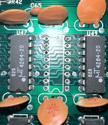
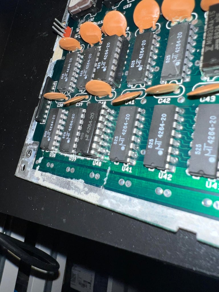
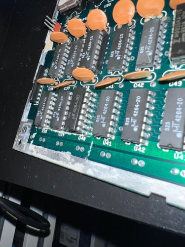
All DRAM chips are MT4264-20. There are notorious for failing. Should be considered replaced.
There is a lot of something that looks like medical tape. I am struggling to see the point of these, but I assume that they are used as some kind of insulation.
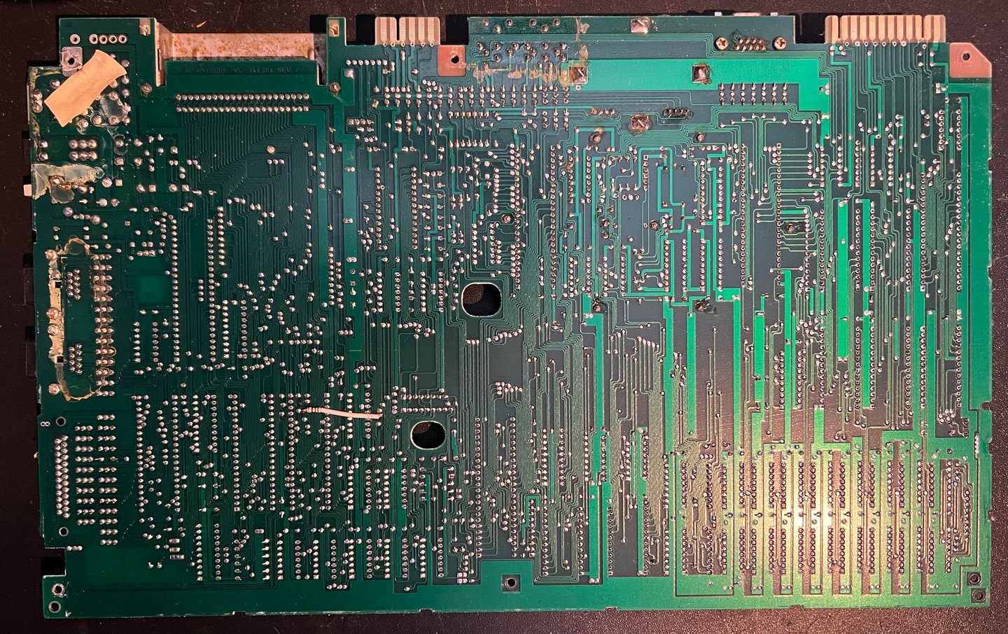
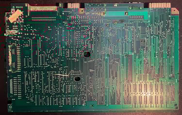
Even if the mainboard is dirty I can not see any signs of corrosion on the board (except for the RF-modulator and cartridge port lid).
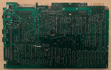
There are some flux residue on the backside of the mainboard from the soldering at manufacturing time
All bodge wires are from manufacturing. I can not see any signs of rework.
In the table below the main chips are listed (before refurbishment - some may be changed during repair if required).
As can be seen from the table above most of the ICs are manufactured somewhere around Q2 1985. So it is a fair guess that this Commodore 128 was produced sometime late autumn in ´85. Perhaps a Christmas gift for a Norwegian child in 1985?
Initial testing
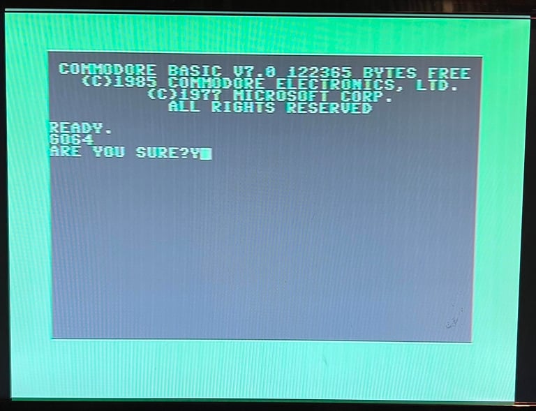
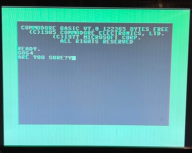
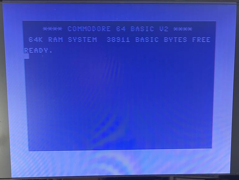
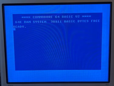
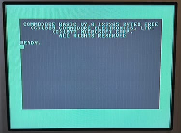
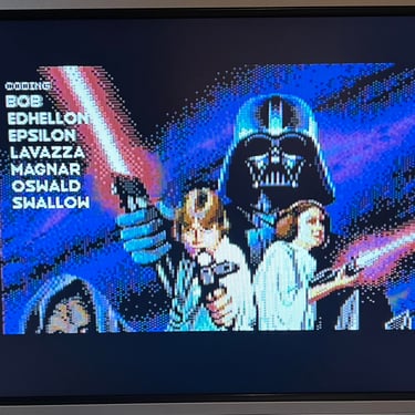
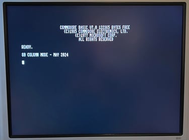
Powering on the C128 result in a: semi-garbled startup screen (?)
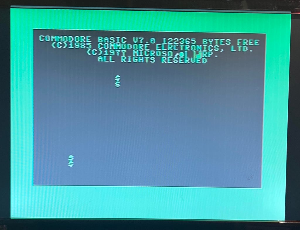

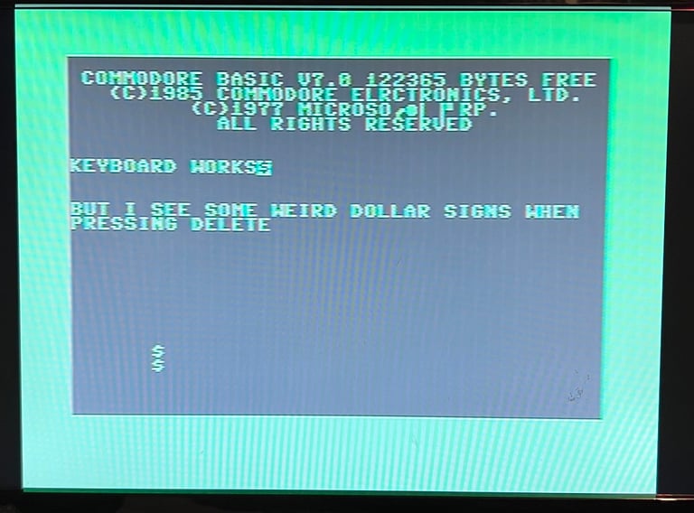
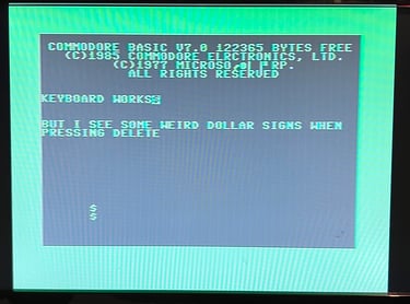
The keyboard, and the machine in general, seems to be semi-operational. You can type on the keyboard and access the Commodore 64 mode, but there is a lot of garbage on the screen.
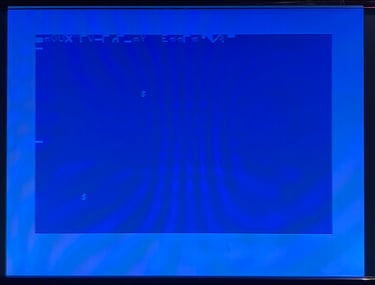
Not very surprising since these machines are getting quite old, but it now means that repair is required. My guess is that this is related to the RAM chips, and that some of these are bad.
Checking the voltages
For the Commodore 128 to work flawlessly the voltage levels needs to be with acceptable levels. The fault symptoms do not suggest that there is an issue with the voltages, but it is good practice to measure these - and to rule out that there is a problem with voltages. In the table below all the measures voltages are listed (this list will also be updated after refurbishment). All the required voltages are present and within tolerances, so there are nothing obvious wrong in that area.
Cleaning the PCB
As previously mentioned the mainboard is very dirty. Even though it has nothing to with the fault I clean the board properly by using plenty of mild soap water and a soft paint brush. Note that all socketed chips are removed before cleaning to avoid water being stuck in the IC socket, and that the old labels are damaged. Some of the grease are removed with isopropanol. Below are some pictures after the cleaning. It looks way better, and makes the repair job more comfortable.

Hot ICs and Dead test cartridge
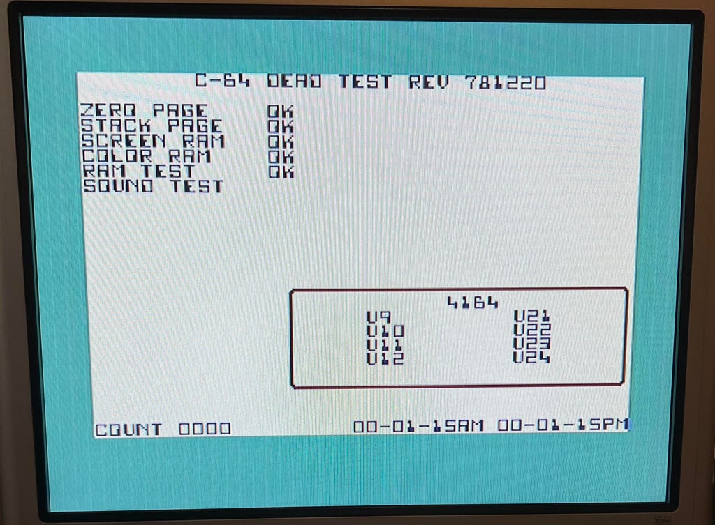
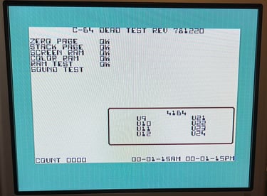
The Dead Test Cartridge is installed in the machine, and while the machine is powered on I also check if any of the ICs are abnormal warm. The ICs are quite warm, but nothing which is not normal as far as I can tell. Even if the Dead Test Cartridge is primarily focused for the Commodore 64 it is designed to work in the Commodore 128 as well (it will automatically force the machine into C64 mode).
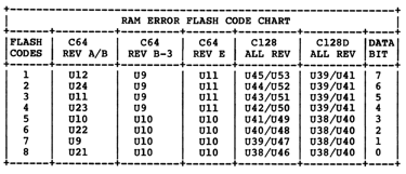
With the Dead Test Cartridge installed the screen flashes six times. According to the diagnostic manual this points to a fault in RAM chip U40 or U48. See table below.

The Dead Test Cartridge do strengthen my hypothesis that there are bad RAM chip(s). Now, there are 16 of these and they should all be replaced actually. These MT RAM chips are prone to fail eventually. But in an attempt to check my hypothesis the U48 IC is desoldered and a socket installed.

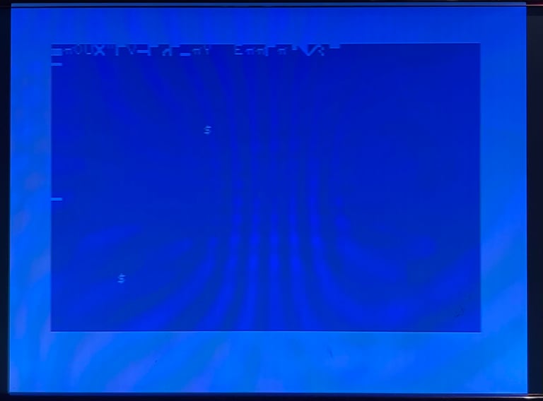
Did that solve the problem? No... actually, with a new know working DRAM chip in place the computer goes light grey and then BLACK (!) after about 10 seconds. So now something else broke... I think that the MT chips are literally just failing in front of me here.
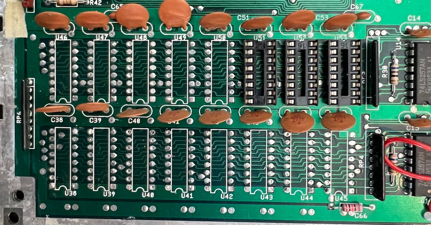
With the the "piggyback" method (placing working chips on top of the existing chips) I make some progress. Below are some pictures from the array of MT RAM with two ICs piggybacked (U40/U51) and one IC socketed (U48).

Now things start to happen! The Commodore 128 bootup screen looks normal, but when entering the Commodore 64 mode the "?OUT OF MEMORY IN 0" error message is displayed.
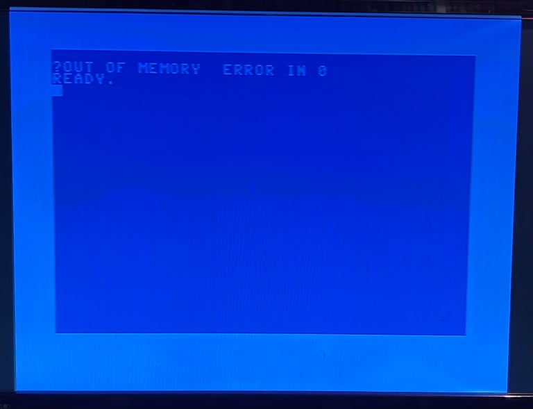

According to the Pictorial C64 Fault Guide the "?OUT OF MEMORY ERROR IN 0" points to a fault in the RAM ICs. No surprise there. Only thing I notice is that there is an additional blank character between the word "MEMORY" and "ERROR". Nevertheless, these MT RAM chips must be removed. All of them!
Following the best 8-bit repair mastermind, Ray Carlsen, all of the 16 DRAM MT chips can be replaced by a device called SaRuMan128. So such a device is ordered from retroleum.co.uk.
Installing the SaRuMan128
SaRuMan-128 replaces the original 16 DRAM used for the C128´s main RAM (made by Eslapion) - not only is it a modern replacement is uses much less power also.
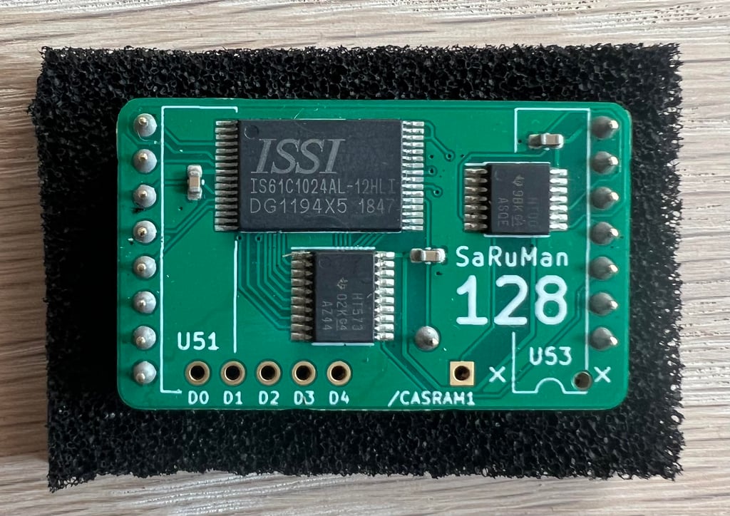

As the SaRuMan-128 replaces all DRAM they must be removed first. This is done by simply cutting all the legs close to the IC body. Not strictly required but the cut pins are desoldered from the mainboard. Looks better and would make it easier if they are to be socketed at some point in time. The U51, U52 and U53 are desoldered and three sockets installed. These sockets will hold the SaRuMan-128.
The following wires are soldered between the SaRuMan-128 and the mainboard:
SaRuMan-128 D0 <> U46 PIN #2
SaRuMan-128 D1 <> U47 PIN #2
SaRuMan-128 D2 <> U48 PIN #2
SaRuMan-128 D3 <> U49 PIN #2
SaRuMan-128 D4 <> U50 PIN #2
SaRuMan-128 /CAS <> U44 PIN #15
And then the SaRuMan-128 is carefully placed in three sockets in U51, U52 and U53.

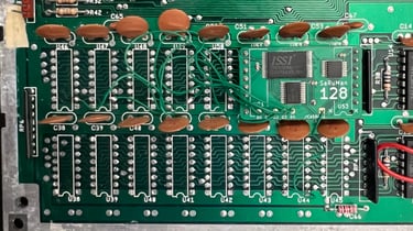
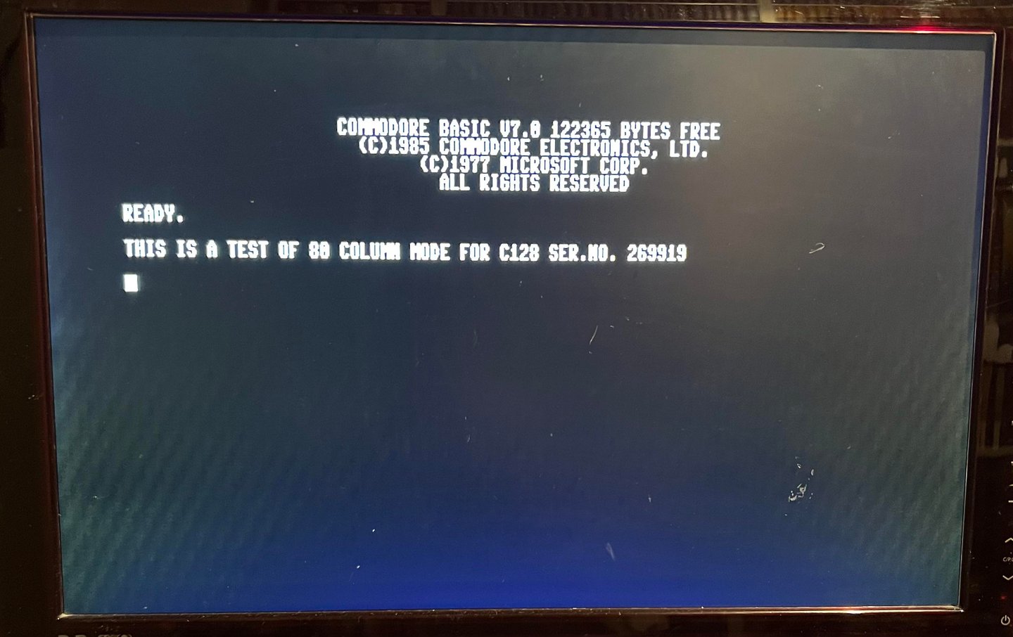
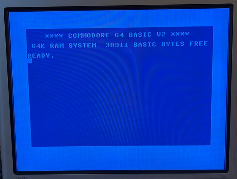
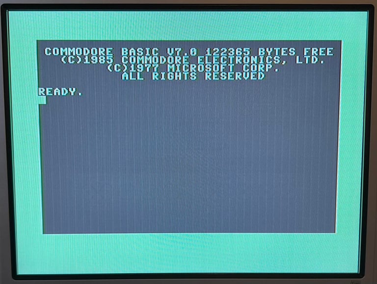
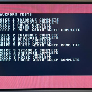
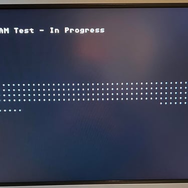
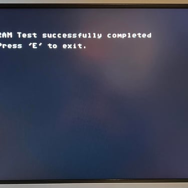
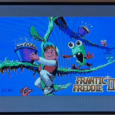
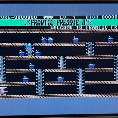
With the new SaRuMan-128 RAM replacement in place it is time to test the machine again. Does it work? Result: SUCCESS! Now both the C128 and the C64 boot screen appear normal. Further testing needs to be done, but this looks very promising!
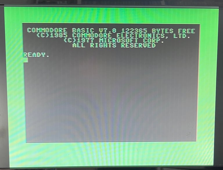


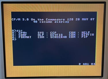
Testing the 80 column mode without proper monitor
The C128 is capable of displaying both a 40- and 80 column screen. It is probably the 40 column mode which is most commonly known since this is the video mode generated by the MOS 8566 VICII-E chip used in both the Commodore 64 and 128 mode. The VICII-E can also generate advanced graphical objects such as sprites in contrast to the MOS 8563 VDC chip which is used for the 80 column mode. The VDC can show limited graphics (compared to the VICII-E), but is superior in displaying text used in business applications.
To test the 80 column mode without a proper monitor, but with a normal TV instead, a composite video cable can be made. But this video cable will only carry the monochrome signal from the RGBI connector. To make such a simple video cable the PIN #7 (Monochrome) and PIN #1 (Ground) from the RGBI port is connected to the center (PIN #7 - Monochrome) and shield (PIN #1 - Ground) on the video cable.
Below is the RGBI pinout shown. This is taken from the website My old computer - see reference documentation.
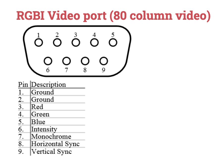
The homemade monochrome video cable is shown below. It doesn´t look good, but it does the job!

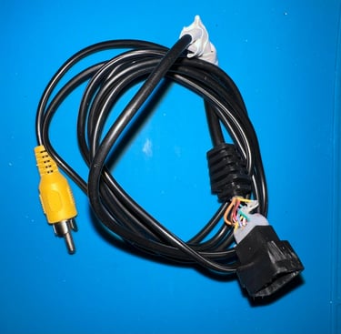
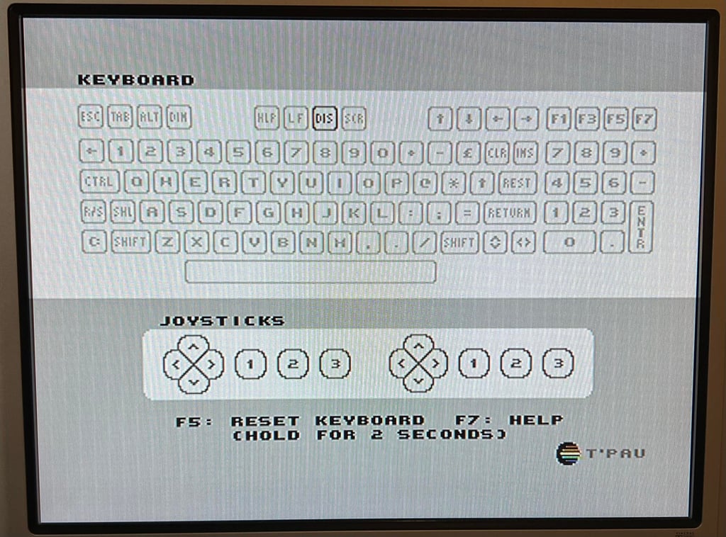
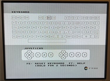
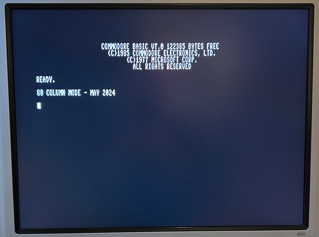
The 40/80 DISPLAY key is pressed and the 80-column mode is displayed. It looks to be fine!

Replacing the electrolytic capacitors on the mainboard
The electrolytic capacitors are almost 40 years old. And these capacitors will dry out eventually. Even if they good be in ok condition it is good practice to replace these fourteen with modern quality electrolytic capacitors. A list of which electrolytic capacitors that are replaced can be found in the library section. Below is a picture of the mainboard after the new capacitors are installed.
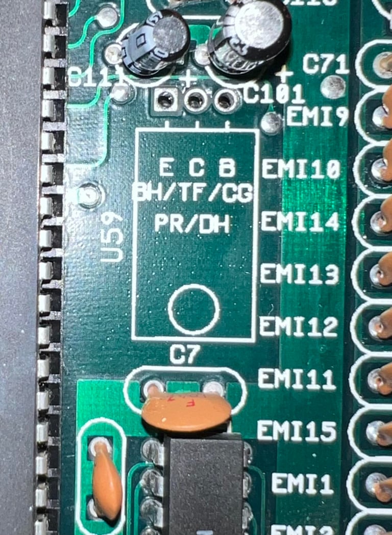
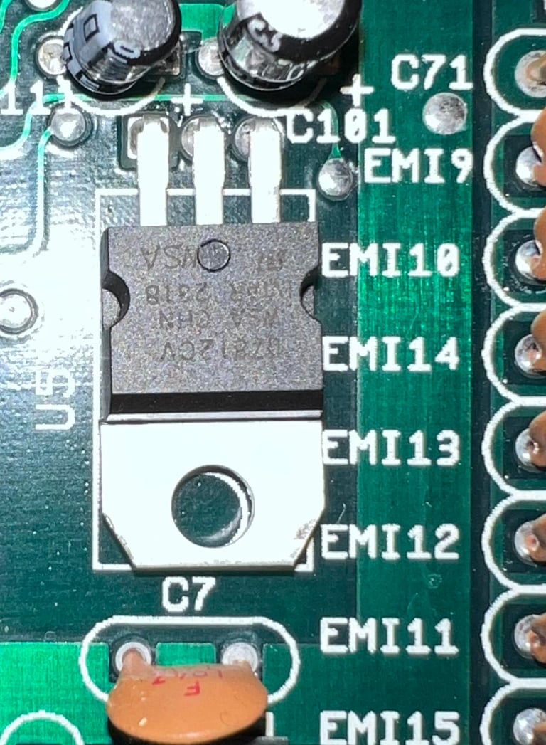
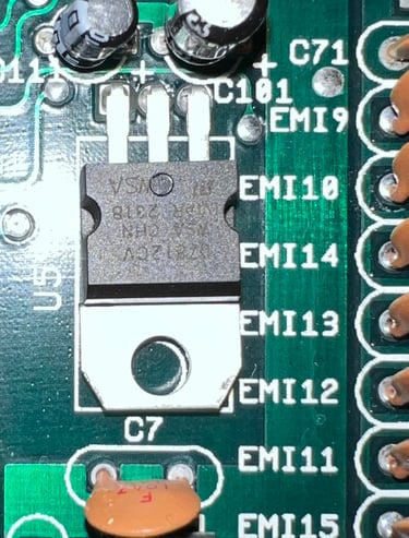
Replacing the 12 volt regulator
There is a 7812 voltage regulator (12 V) on the mainboard (marked U59). As part of best practice for refurbishment this is replaced with a modern replacement. The old 7812 is desoldered without any damage on traces and pads, and the new 7812 regulator is soldered in place. See pictures below.


