
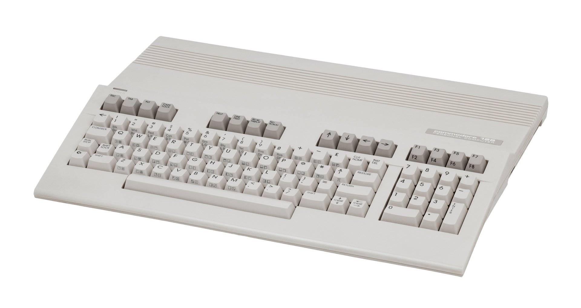
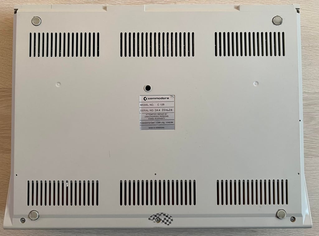
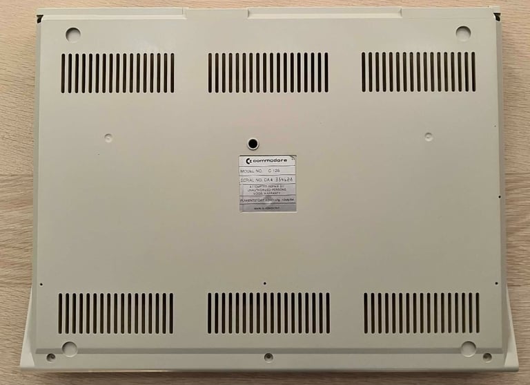
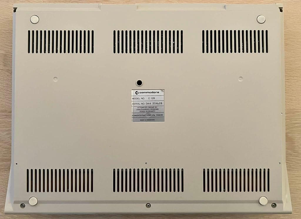
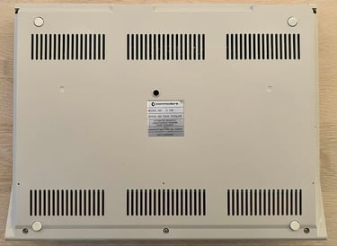
C128 [PAL]
Ser. No. 354628
Artwork 310381
(REV 9)
Starting point
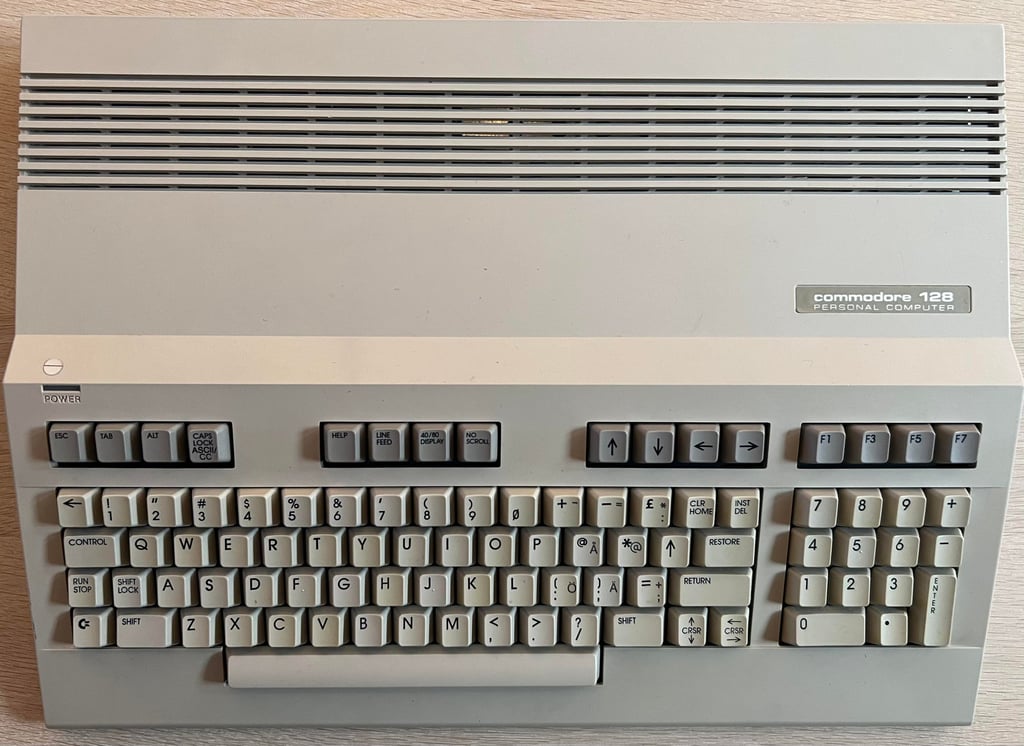
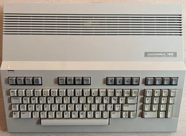
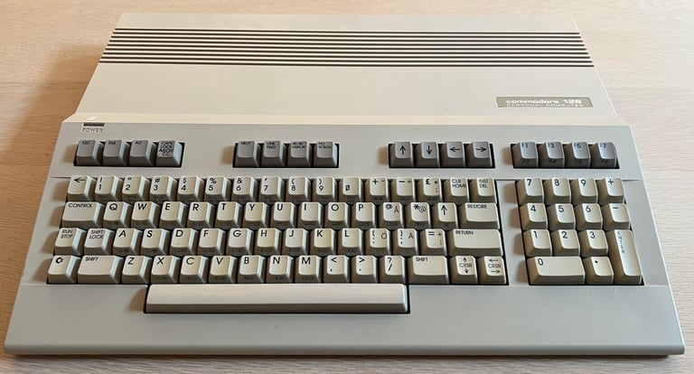
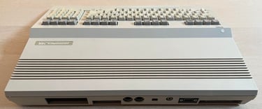
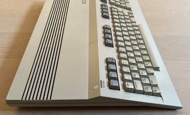
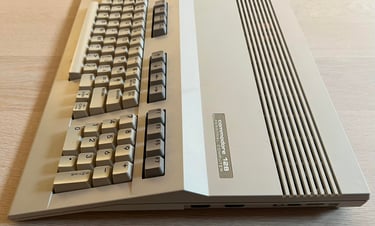
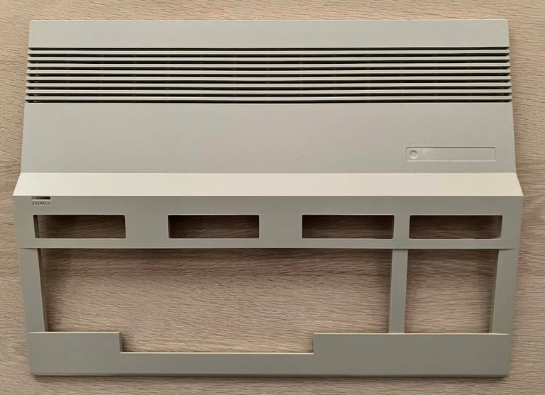
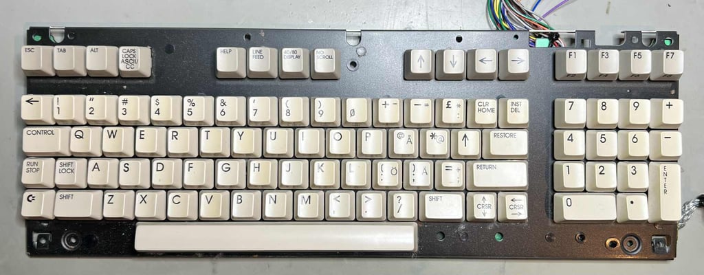
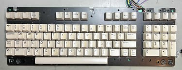
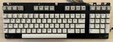
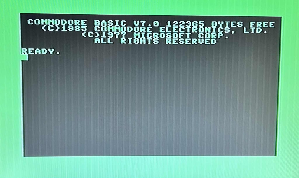
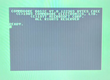
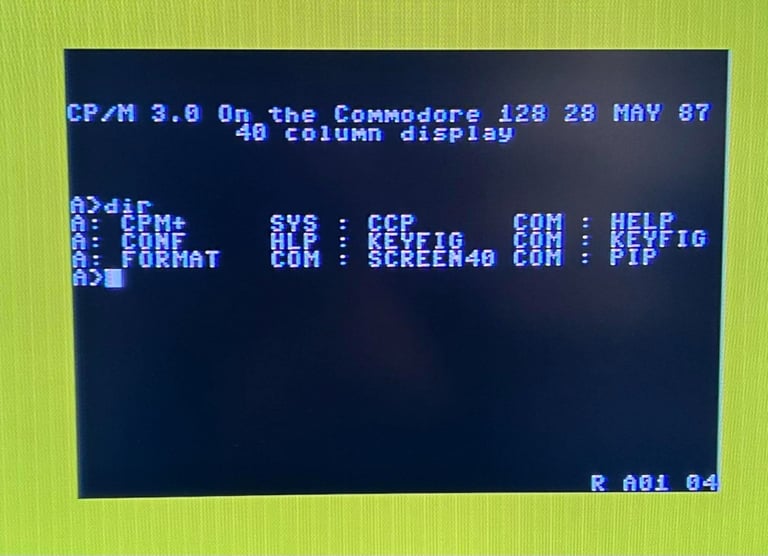
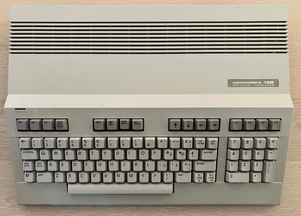
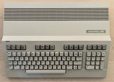
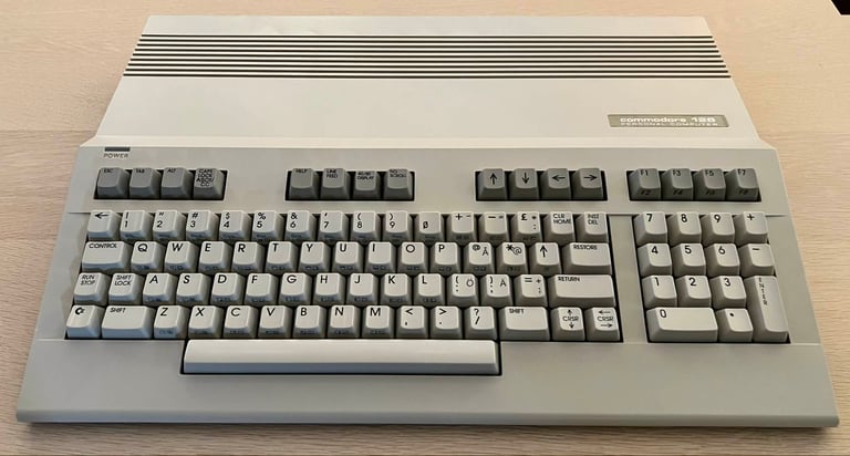
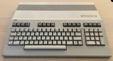
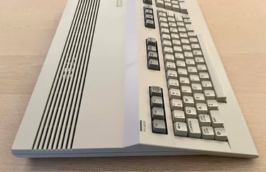
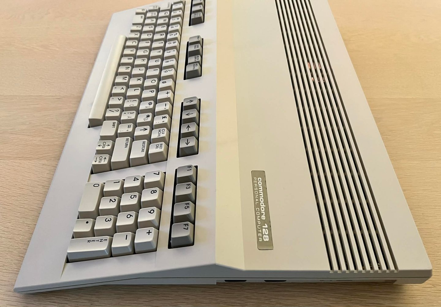
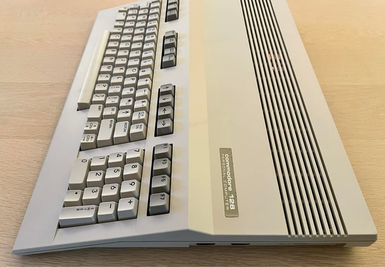
This Commodore 128 looks quite good on the outside, but it is known to be not working unfortunately. The machine is reported to not start up in either C128 or C64 mode. But, aside from not working, the casing and keyboard looks to be undamaged and with little signs of use. Notice that the keyboard layout is Swedish characters «Å», «Ä» and «Ö». In the picture gallery below you can see the machine before refurbishment and the corrupted startup screen for both modes.


Refurbishment plan
The refurbishment plan for this flat C128 (several of them in parallell):
- Refurbish the casing (cleaning, repairing and retrobrighting if required)
- Refurbish the keyboard (cleaning, reviving the plungers and maybe retrobrighting)
- Refurbish main board (cleaning, checking, repairing, replacing capacitors and voltage regulators, adding heat sinks etc.)
- Recap RF-modulator
- Verify operation by testing
The plan can be updated during the refurbishment process. Sometimes I discover areas that needs special attention.
Disassembly
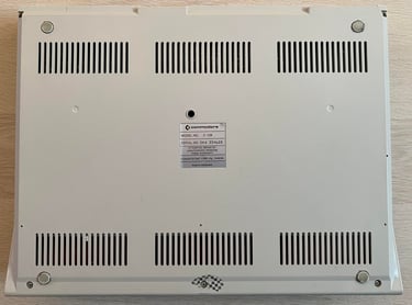
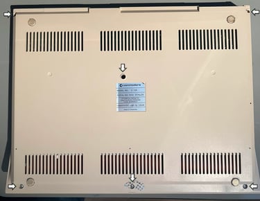
Opening the Commodore 128 is not complicated, but it is a good idea to be a bit careful to not break the small plastic parts. First the six screws are removed from the bottom cover.
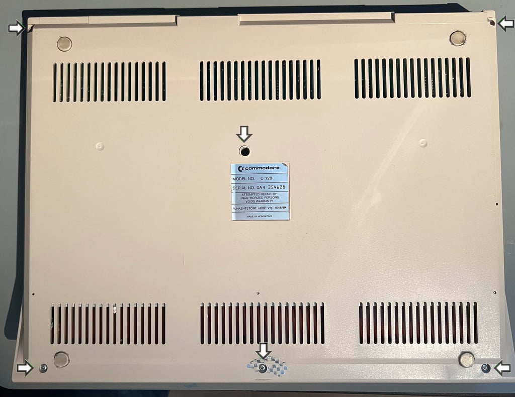
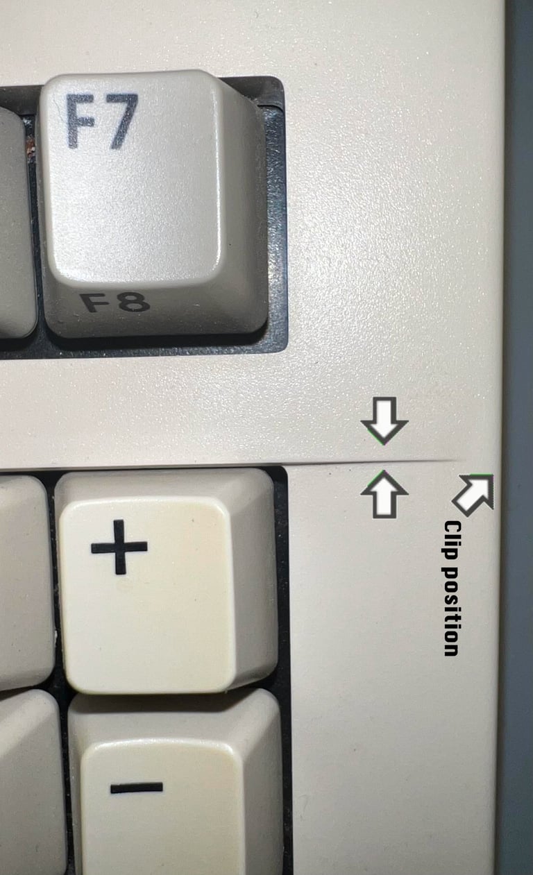
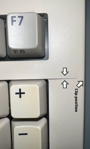
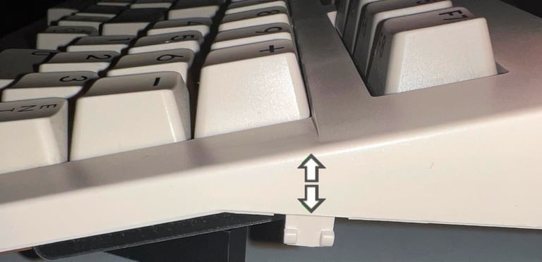
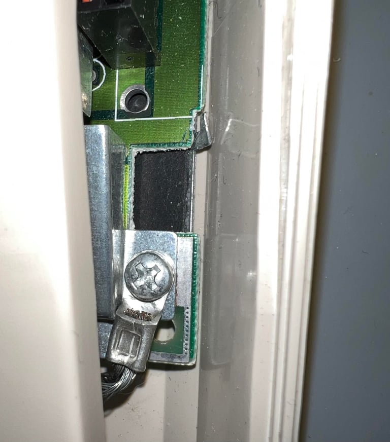
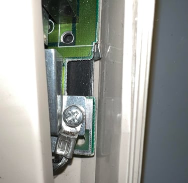
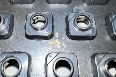
Next step is a bit fiddly. On each side, parallell to the thin line running along the keyboard, there is a small plastic clip. These clips holds the top- and bottom cover together. To release the clips a small "plectrum" from the Pro Tech Toolkit is used to pry the covers apart. Below is a picture showing the position of the clip (seen from above) and a picture of the clip when released (seen from the side).

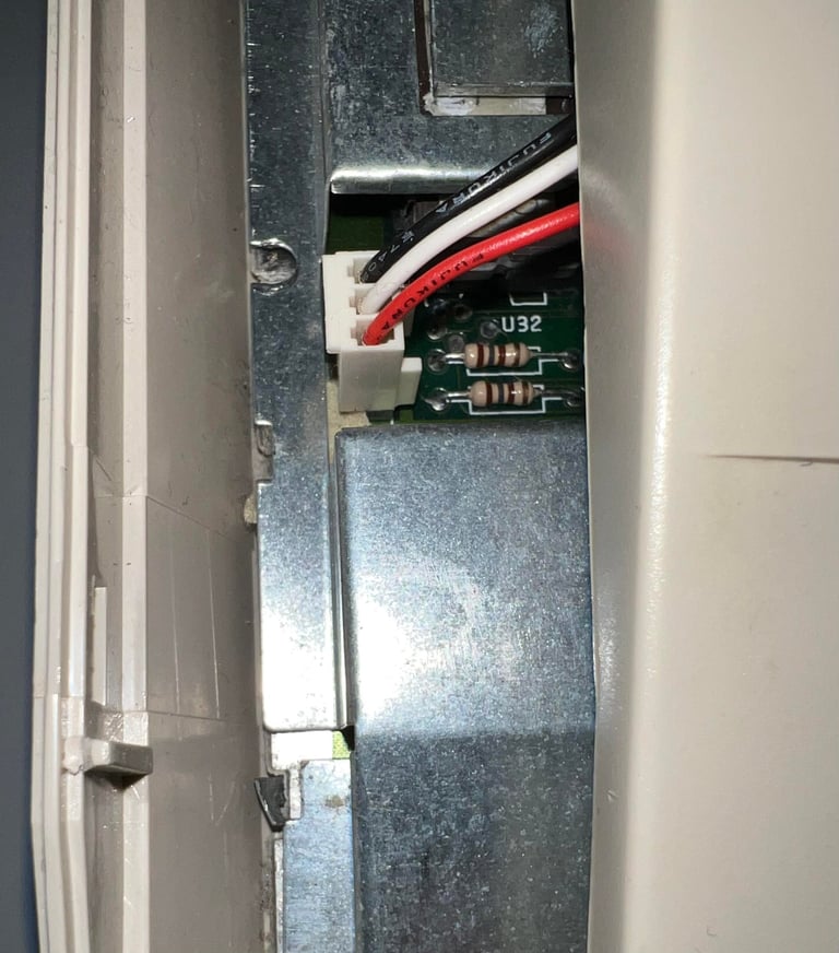
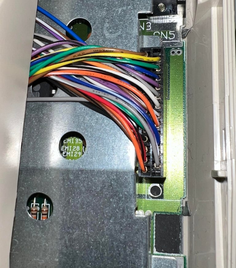
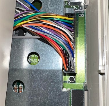
With the clips released, but the top cover not completely removed, the next steps are to remove the ground screw, the keyboard LED and finally the keyboard connector. The ground screw can be found on the right side of the keyboard, and the LED connector on the left hand side. Same as the ground screw the keyboard connector can also be found on the right hand side. See pictures below.
Now the top cover can be lifted from the bottom cover. The inside is revealed showing a large RF-shield (which is also functioning as large heat sink for the ICs). It looks to be in quite condition

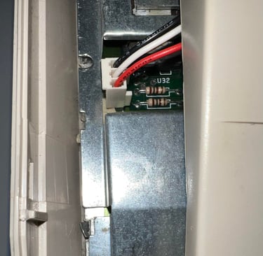
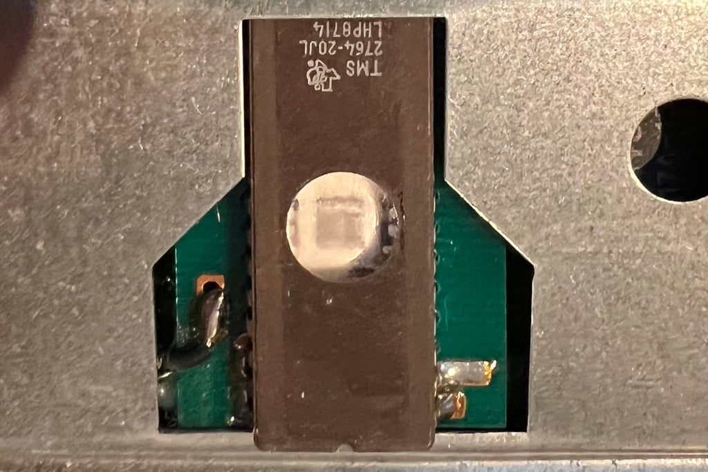
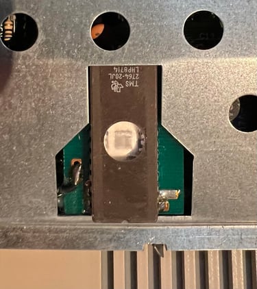
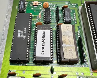
Notice that there is one IC which is visible through the RF-shield. This IC is an EPROM containing the character ROM, but the circular glass window is open! An EPROM is erased by exposing UV light to it. Not that there is much UV light inside a closed Commodore 128, but this window should covered.
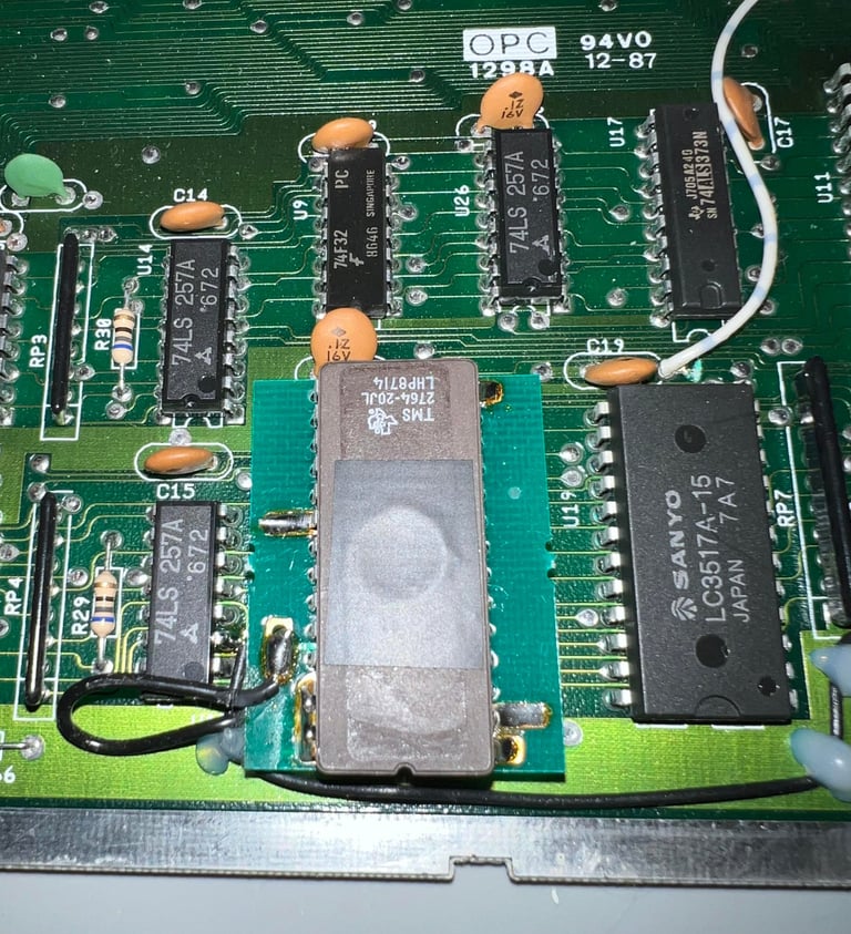
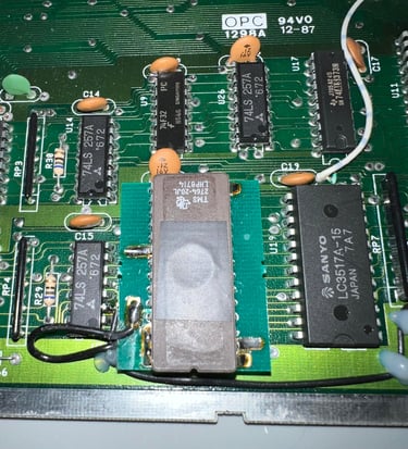
The RF shield is removed and at the same time some tape is placed on the character EPROM (U18) to prevent any damage by UV light.
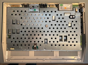
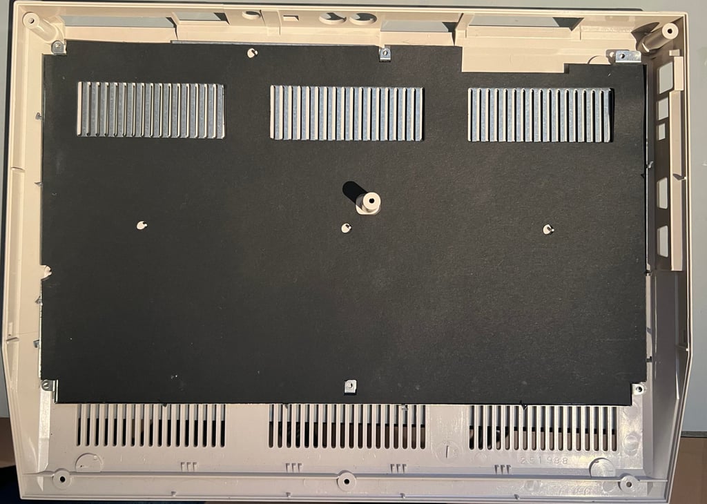
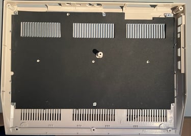
Finally the mainboard is lifted from the bottom cover. The bottom cover looks to be in fine condition. Some dust and dirt, but otherwise it looks good.
Casing
The top and bottom cover are in good condition as can be seen from the "Starting point" chapter. There are some dust, grease and sticker residue, but otherwise in quite good condition.
I am not quite sure if the "Commodore 128" label would withstand a thorough cleaning. Therefore the sticker label is removed with some hot air (from a hairdryer). This causes the label to bend a little bit unfortunately, but I think this should be ok. These badges can be replaced, but I do not think that is required. Also, the four bottom rubber feet are removed before cleaning.
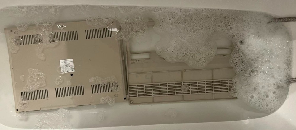
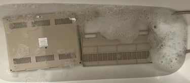
The top- and bottom cover are soaked in mild soap water for about 48 hours. This should remove most of the dust and grease.
After the long bath there are still some marks to clean. To remove these some isopropanol and Q-tips are used. Below are some pictures of the top- and bottom covers after cleaning.


Keyboard
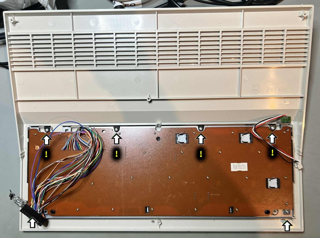
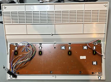
First step is to remove the keyboard from the top cover. To do this the six screws (see picture below) are removed. NOTE: beneath the four screws at the top there are some small plastic wedge parts. It is good practice to keep these together with the screws to reduce the risk of loosing these.
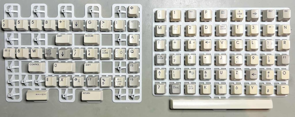
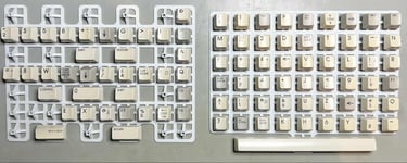
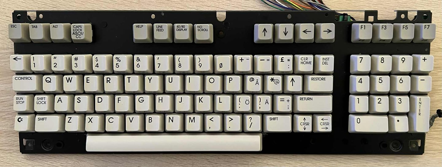
The keyboard is in quite good condition, but there are quite some dust and grease beneath the keycaps. Also, the keycaps are quite yellowed. But besides that, the keyboard appears to be in good condition.
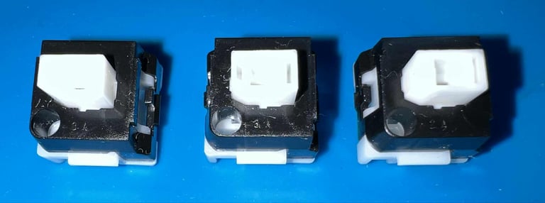
All the keycaps are removed with a keycap puller. By using a keycap puller the risk for damaging the keycaps, and the plungers, are significantly reduced. NOTE#1: there are some "U" shaped metal brackets beneath the "ENTER", "RETURN" and "0-keypad". NOTE#2: in addition to a normal spring, there are two small additional springs beneath the spacebar.

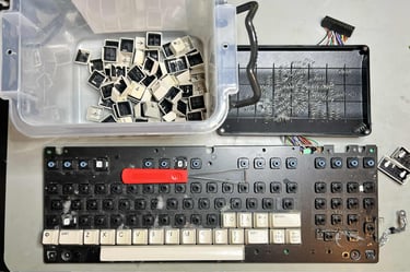
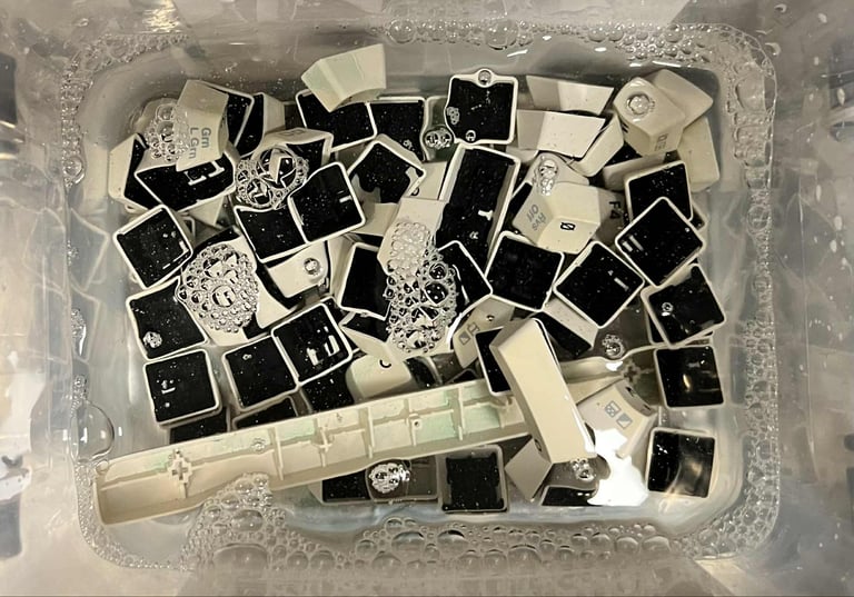
All the keycaps are placed in a box filled with mild soap water for about 24 hours. This will dissolve most of the grease and dust - preparing the keycaps for some retrobrighting.

To ease the job of applying the 12 % hydrogen peroxide cream the keycaps are situated on a 3D printed mount.
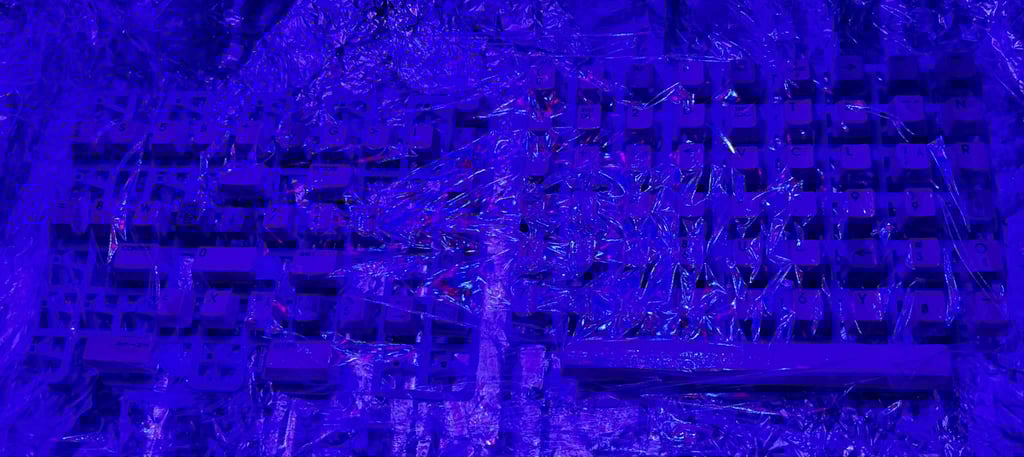
The keycaps are retrobrighted for about 12 hours straight. During this period the 12 % hydrogen peroxide cream is applied regularly. The keycaps are covered in cling film while exposed for UV light.

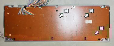
Next action is to remove the three LOCK buttons (40/80 display, CAPS LOCK and SHIFT LOCK) and all the small screws. The wires connecting the three LOCK keys are desoldered (see arrows below where these are situated), and the LOCK keys are pushed firmly from the backside of the keyboard towards the front. This will make then pop out.

The three LOCK keys are cleaned with some isopropanol. They look good as new I think.

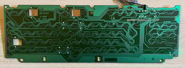
The keyboard PCB is carefully lifted from the metal bracket. This is a MITSUMI C-128F 56 7565 keyboard PCB with carbon pads. To clean the keyboard PCB only some distilled water is used - this is to prevent damage to the carbon pads. Below is a picture of the keyboard PCB after cleaning.

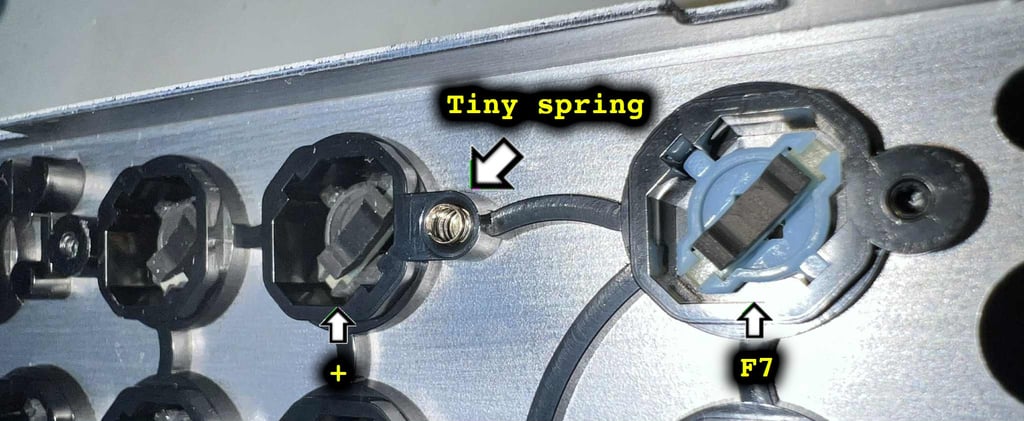
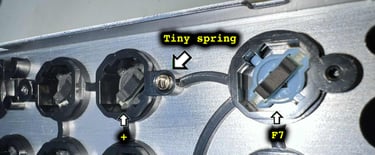
WARNING: Before removing all the plungers from the metal bracket, notice that there is a tiny spring - situated approximately beneath the "F7" and "+" key. This little spring is connecting the metal bracket to the PCB. See picture below.
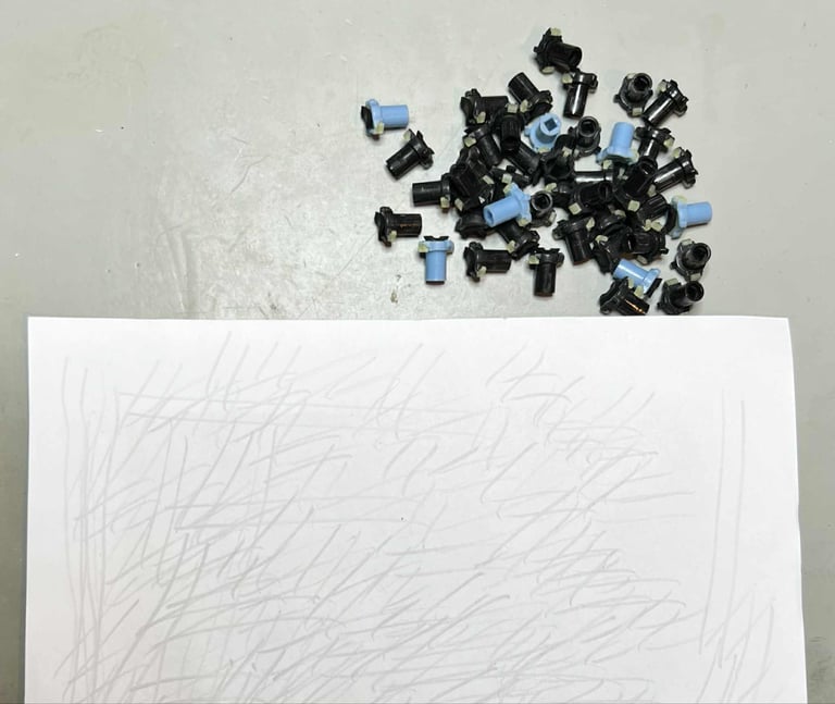
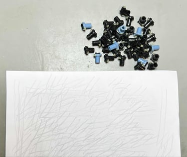
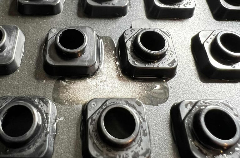
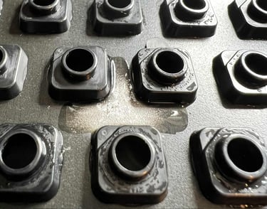
Reviving the plungers is done by using a little trick: by carefully dragging the plungers across a sheet of paper, the dust and grease on the conductive rubber is removed. My experience is that this is both a more effective, and gentle, method compared to cleaning them with e.g. isopropanol.
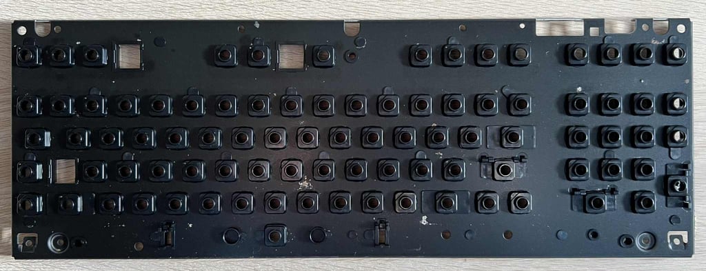
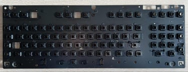
The metal frame holding all the plungers is very - VERY - dirty. To fix this, the frame is cleaned properly with mild soap water and a clean paint brush. It looks very good after the cleaning. But as can be seen from the picture below, there are some areas with corrosion. This is not a very big deal, but it should be taken care of.
First is the area(s) scraped and cleaned with a combination of a sharp pick tool and a glass fibre pen. Then the corrosion is exposed to some vinegar for a few minutes. This is to stop the corrosion from expanding. Finally, everything is cleaned properly with mild soap water and isopropanol. To secure the area it is covered with some transparent nail polish.

When all the keyboard parts are refurbished the are re-assembled. The keyboard now looks good as new (!).
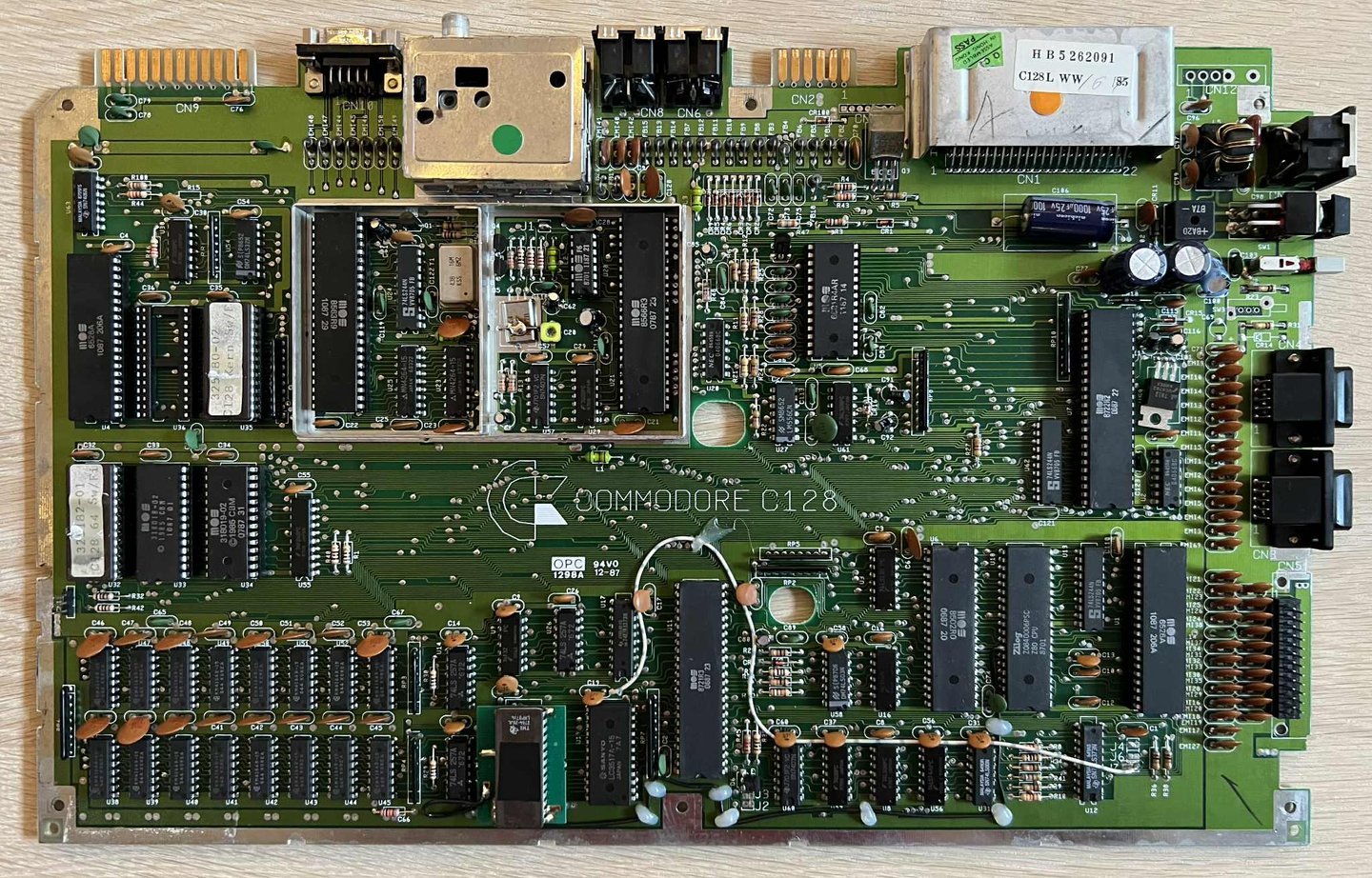
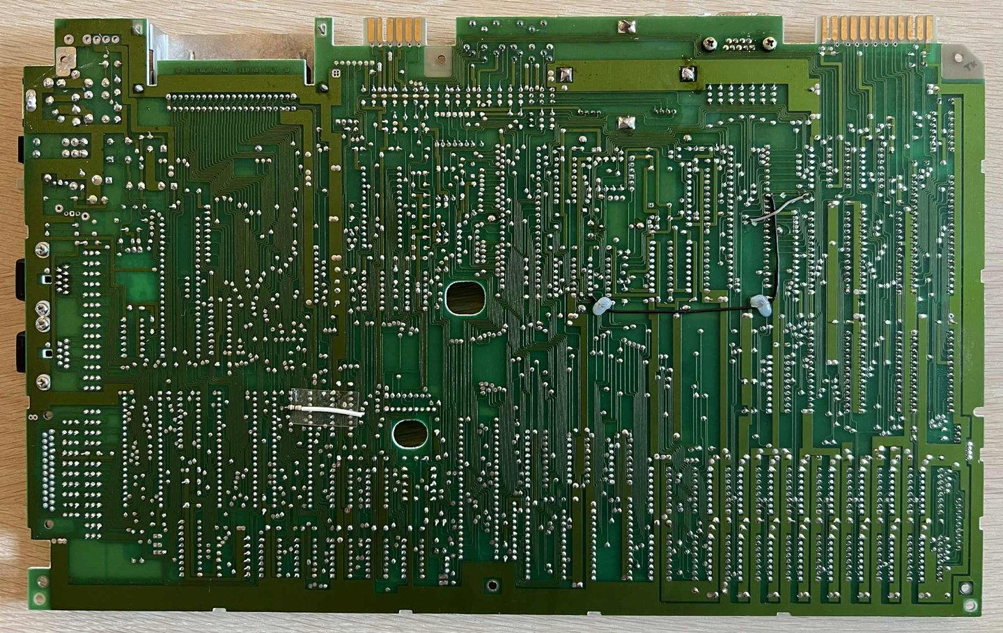
Mainboard
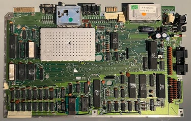
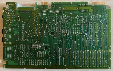
This mainboard is version Artwork 310381 (Rev 9). It looks to be in quite good condition. There is a significant amount of dust and grease on the mainboard, but other than that it looks ok. As previously mentioned this mainboard is known to be not working. Below are some pictures of the mainboard before refurbishment.


Initial testing
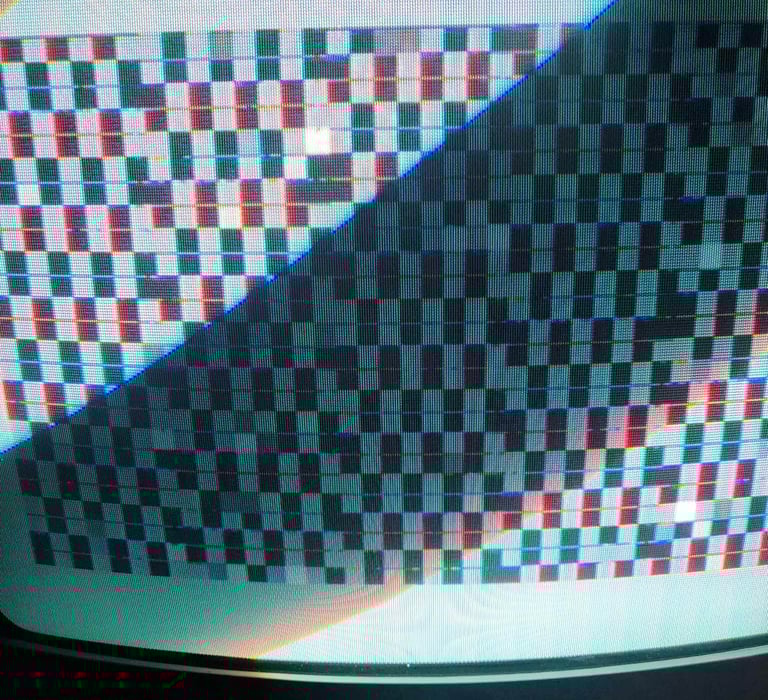
The mainboard is connected to a known good power supply and a TV via the A/V connector. No big surprise here but the result is:
A SCREEN WITH GARBLED CHARACTERS (see picture below)
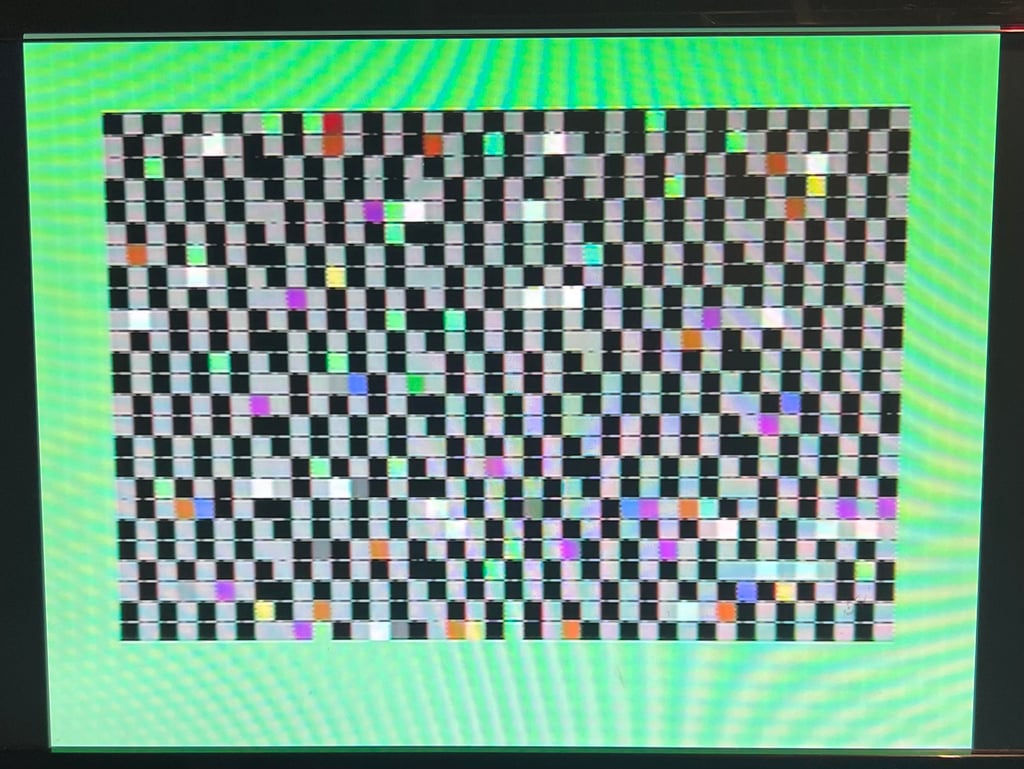

Even if the screen is a complete mess there are something good here. It appears that the VIC-IIe and CPUs are working. Otherwise I do not think it would produce any graphics at all.
Visual inspection
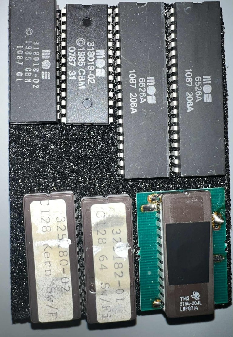
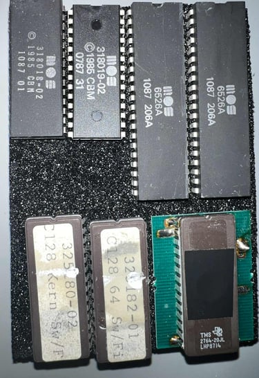
As mentioned the PCBA is full of dirt and grease. But I can not see any sign of damage, corrosion or rework. There are some bodge wires across the mainboard, but this is from factory. All the ICs are present, and the EPROMs are covered with stickers (and some tape on the EPROM U18).
But now I notice something interesting... the EPROM in U18 appear to be loose from the socket. This is the very same IC which I had to place some insulation tape to prevent exposure to UV.
The EPROM IC is carefully removed, the socket cleaned with contact cleaner, and the EPROM is put back. Now the machine is powered on again, and LO-AND-BEHOLD! The machine boots up!

Cleaning the PCB
Although not strictly required, I think it is good practice to clean the PCB. There is a significant amount of grease and dust on the PCB. Before the PCB is cleaned all socketed chips are removed. This is not because the ICs can´t handle the cleaning, but because small drops of liquid can get "stuck" in the sockets and also that the paper labes of the IC will disappear.
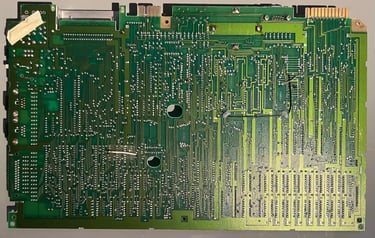
The PCB is cleaned with mild soap water (using a soft paint brush), and rinsed with water before left to dry for a couple of days. Below are some pictures of the mainboard after cleaning.
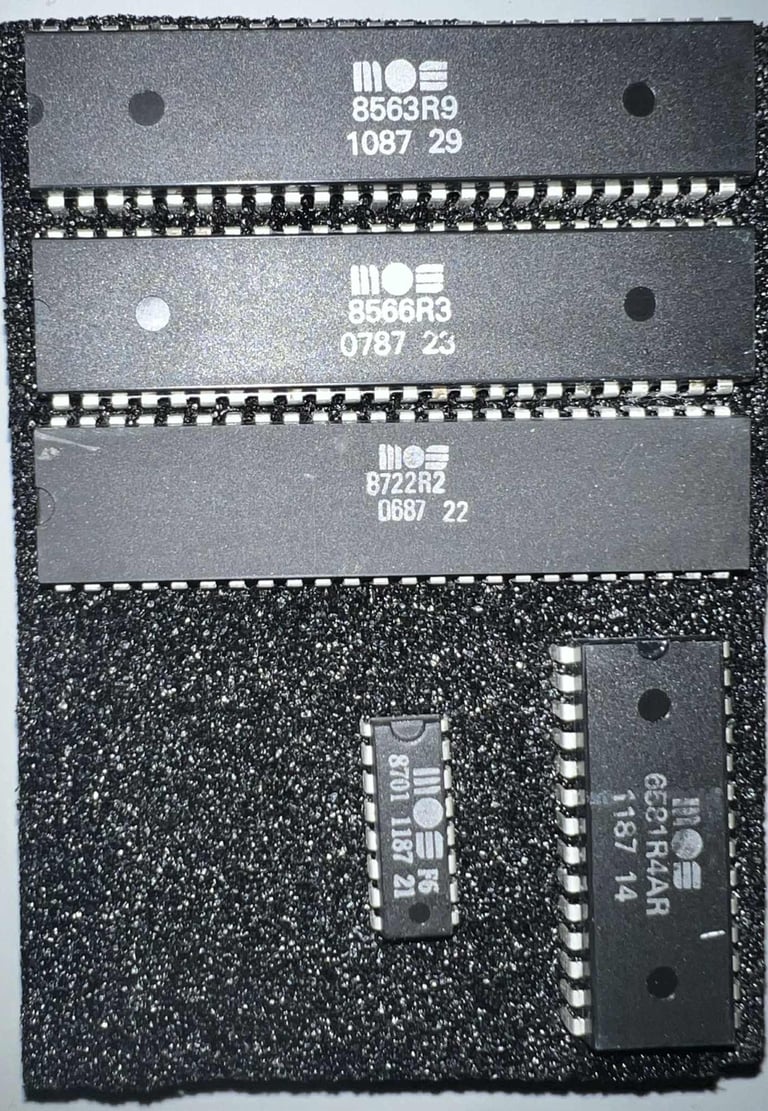
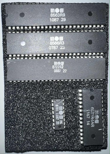
In the table below the main chips are listed (before refurbishment - some may be changed during repair if required). As can be seen from the table above most of the ICs are manufactured somewhere around Q1 1987. So it is a fair guess that this Commodore 128 was produced sometime late winter/early spring in ´87.
Checking the voltages
For the Commodore 128 to work flawlessly the voltage levels needs to be with acceptable levels. The fault symptoms do not suggest that there is an issue with the voltages, but it is good practice to measure these - and to rule out that there is a problem with voltages. In the table below all the measures voltages are listed (this list will also be updated after refurbishment). All the required voltages are present and within tolerances, so there are nothing obvious wrong in that area. NOTE: the +5 VDC is a bit low, but I think this is due to the power supply. But I will keep an eye on that.
Initail testing with the Diagnostic ROM
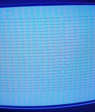
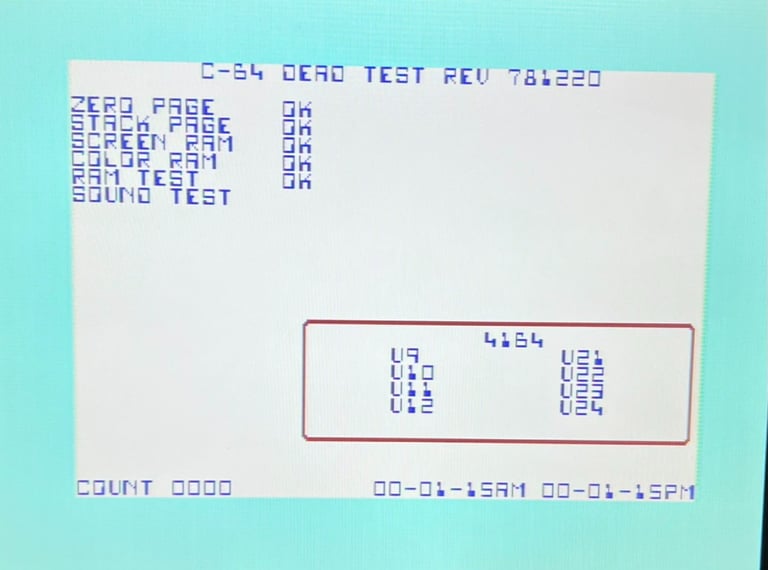
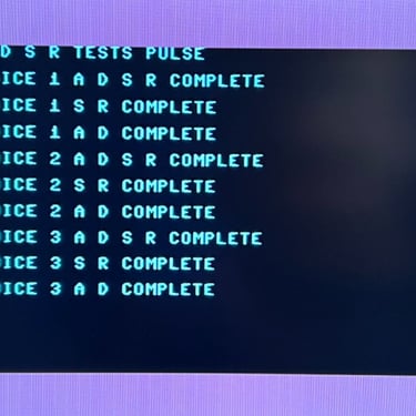
The machine appears to be working OK, but to get a better picture if this is the case the Diagnostic ROM (REV 789010JB) is installed in the U36 socket. Also the test harness (586220) is used together with the diagnostics.

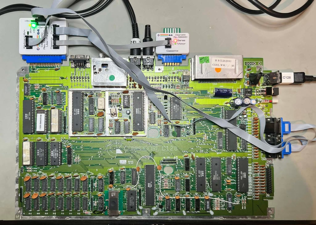

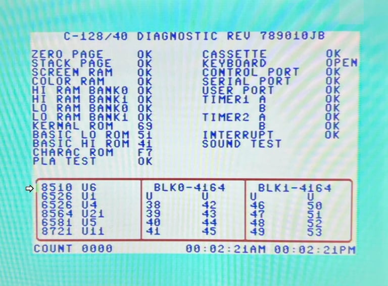
It is good to see that all the tests pass with flying colours. No faults reported. But there is something I notice: there seems to be a fault in one of the the colour lines on the left side (see small arrow). This does not mean that there is a fault here, but I think it is worth checking.

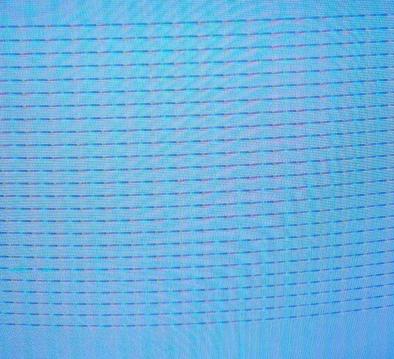
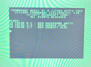
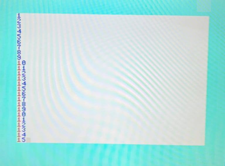
Checking the odd looking colour
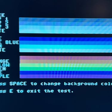
As seen from the picture above it looks like there is a fault in the colour in one on the 40 x 25 char matrix. The first position in line 18 is not showing the red colour. A simple check to see if the machine is capable of displaying a red character on a white background is made. The background is first set to white (and border to cyan) and then all chars set to blue first. Then the char at position (18,1) is set to red. And as can be seen in the pictures below this works fine. So the machine has no problem in displaying a red character on white.


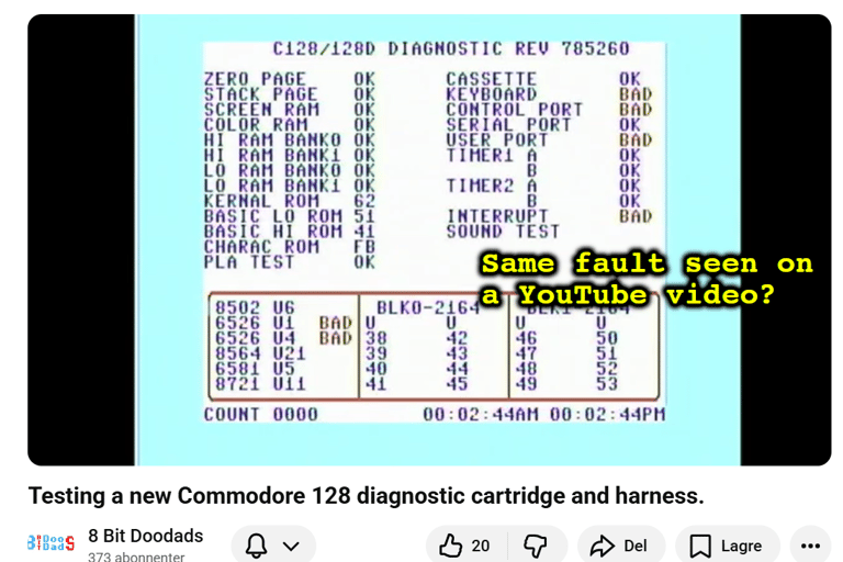
I does appear to me that this is a bug in the diagnostic software more than a fault. Also, during some investigation I come across a YouTube video "Testing a new Commodore 128 diagnostic cartridge and harness" from "8 Bit Doodads". And in this video I notice a familiar bug (?) - the missing red colour on line 18 position 1. So, I will leave this issue for now thinking that this a bug in the test software.
Testing
NOTE: The colours on the test pictures are wrong. This is due to an issue with the TV and not the machine. The pictures does show the functionality nevertheless.
Testing a C128 is like testing three machines: C64, C128 and CP/M (Z80). Most of the testing is based on the C64 mode since this is where most of the test tools are available, but also since these chips are used for the C128 as well.
Testing is done through three main stages:
Testing the basic functionality and chips (C64/C128 mode)
Testing the extended functionality of all chips with the Diagnostics Cartridge and harness.
Testing by using the machine playing demos, games etc. accessed by both floppy and datasette to verify correct operation (C64/C128)
Testing C128 and Z80 specific features: 80 column mode (VDC chip) and CP/M mode

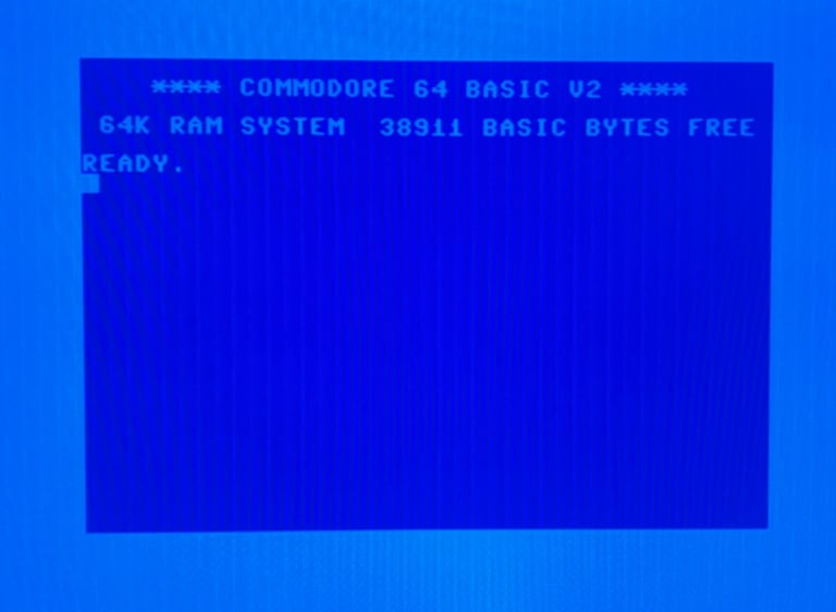
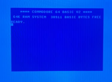
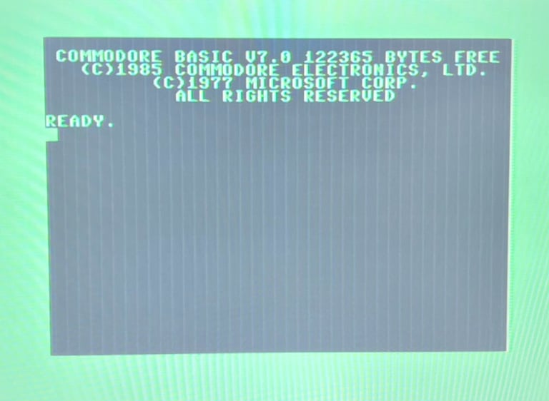
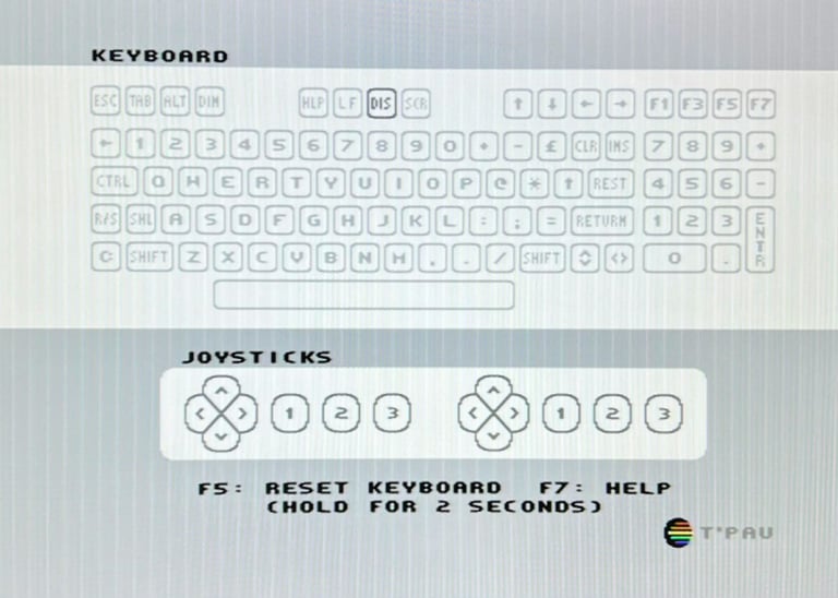
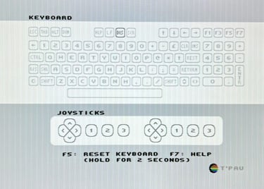
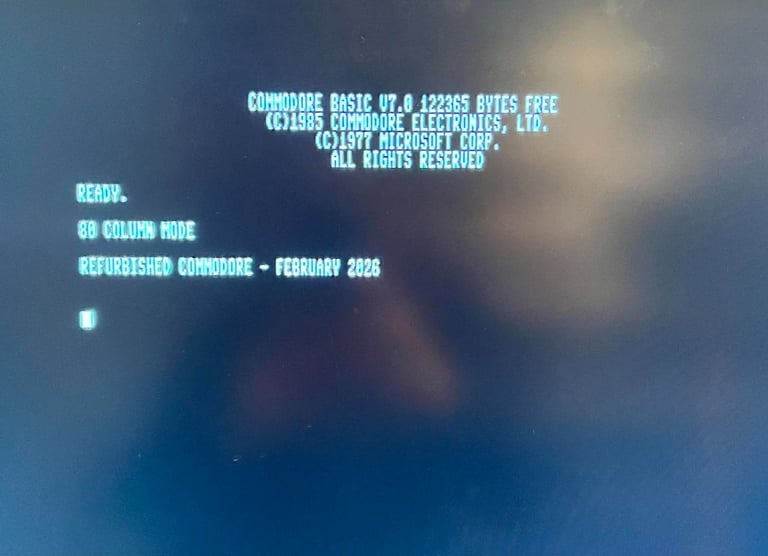
Next test is to power the Commodore 64/Commodore 128 to the boot up screen and also check the keyboard to make sure all keys works as they should. The test is passed; all keys works and 38911/122365 BASIC Bytes Free. Note that the 40/80 column display is disabled in the key test. The 40/80 column mode will be tested separately.
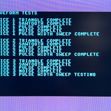
The basic functions of the VIC-IIe, SID and RAM is tested with 64 Doctor and Commodore 64 SID tester. Note that this is to be considered as basic functionality - more advanced (?) functionality such as sprite handling / collision detection / advanced audio will be tested later. But the basic tests pass without any detected faults (click to enlarge).
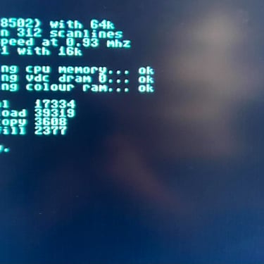
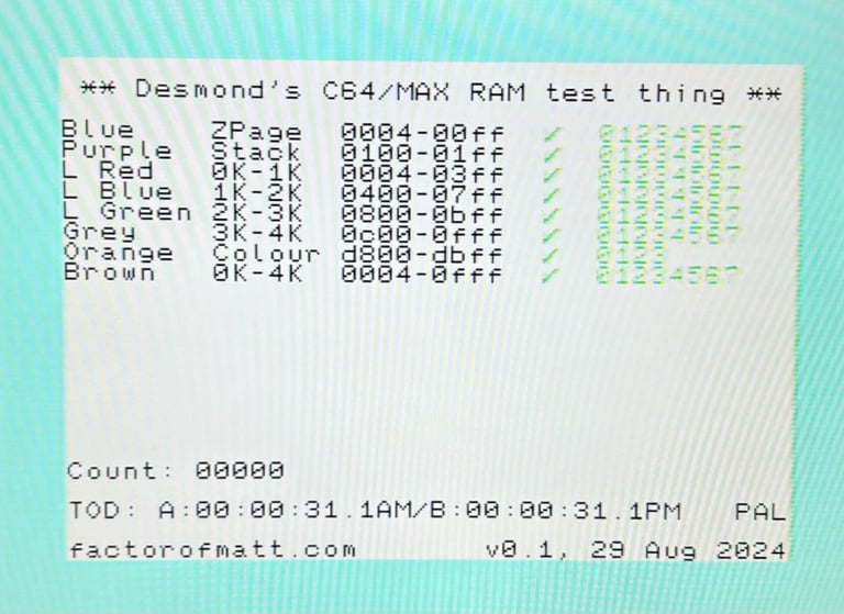
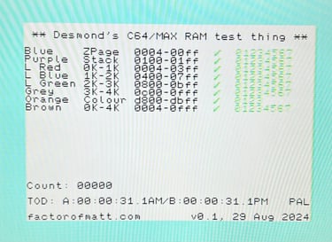
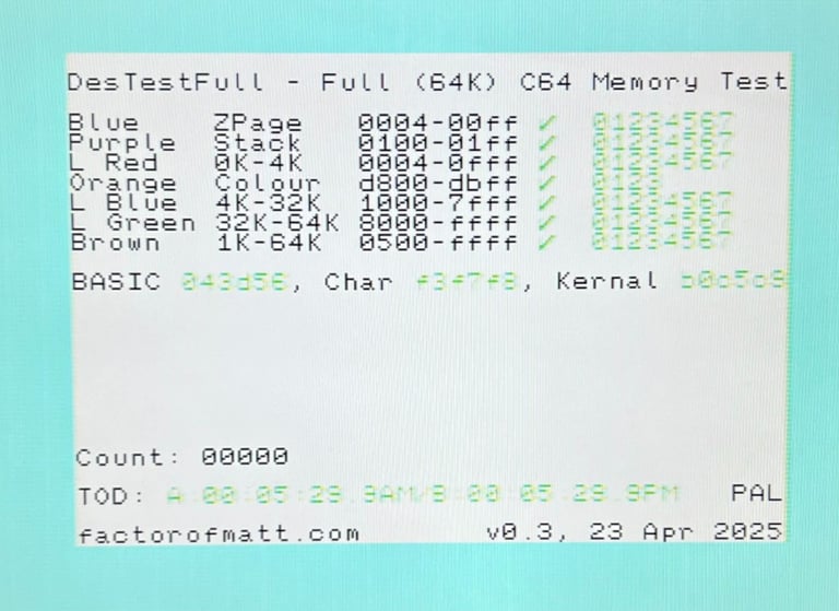
The 64 kB of RAM can be tested thoroughly with the DesTestMax (and Full) cartridge. This is a full March-B memory test of the 64 kB of RAM.
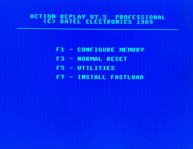
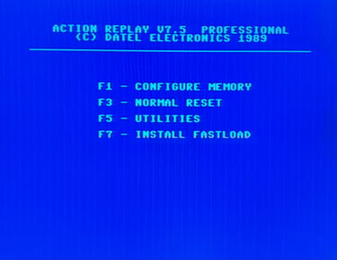
Last basic check before moving to more extensive testing is checking the cartridge. This is done by using the Action Replay cartridge. Result is that the test is passed.

Extended testing
NOTE: Please ignore the poor image quality. This is only due to a poor TV display, and not the machine.
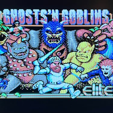
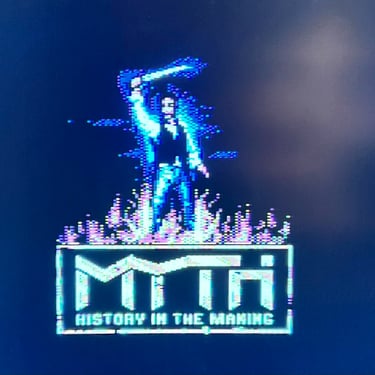
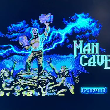
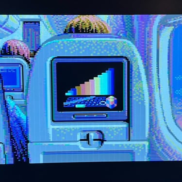
Knowing that the basic functionality of the machine works I continue the testing by using the Commodore 128 for normal operations; playing some games, watching demos, floppy and using a cartridge. I can not find any issues with this machine. I also pay special attention to the video to make sure that there are no glitches in the graphics - I can´t see any abnormalities. Below is a gallery with pictures from the testing.
80-column mode (VDC) and CPM/M
The Commodore 128 is capable of producing a 80-colum mode (in colours) using the MOS 8563R9 VDC chip. I do not have a proper monitor to test this, but the custom made monochrome cable described in earlier chapter is used. To activate the 80-column mode the "40/80 DISPLAY" key is pressed. This will disable the normal screen (making it secondary) and switch to 80-column mode on the RGBI-port. As the picture below shows the RGBI output (in monochrome) is present and working.


Final result
"A picture worth a thousand words"
Below is a collection of the final result from the refurbishment of this Commodore 128. Hope you like it! Click to enlarge!
