

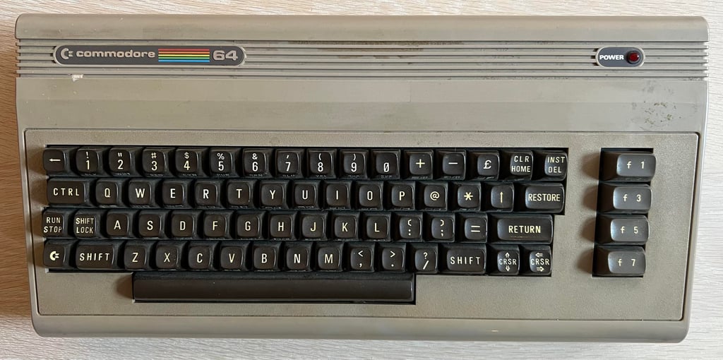
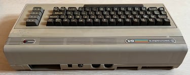
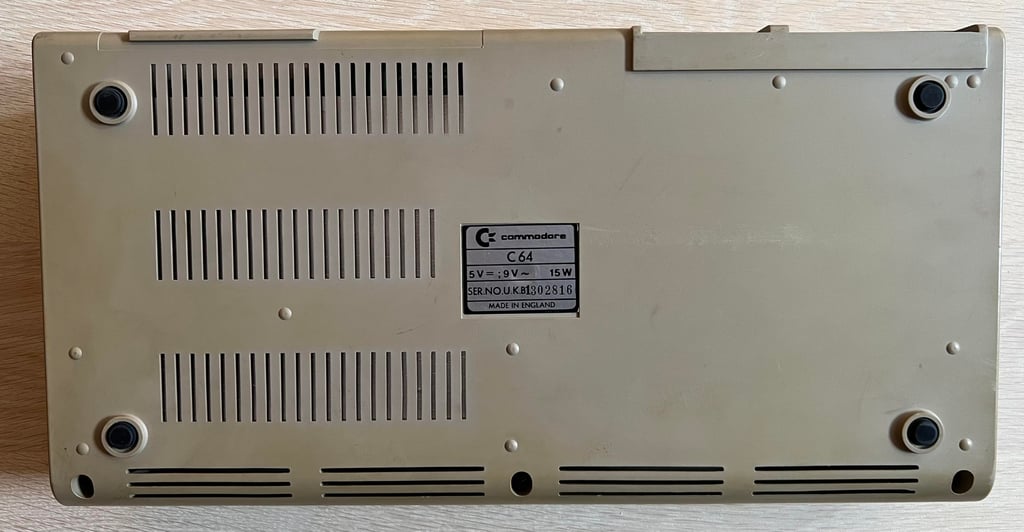
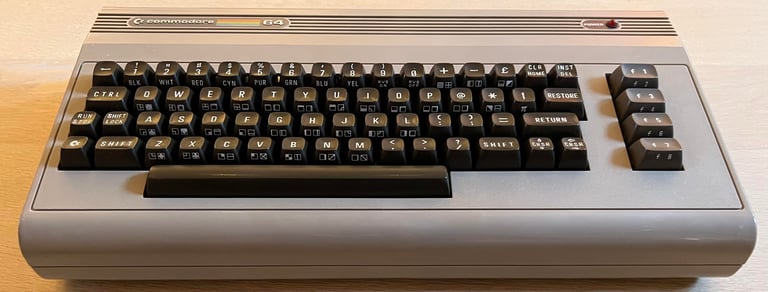
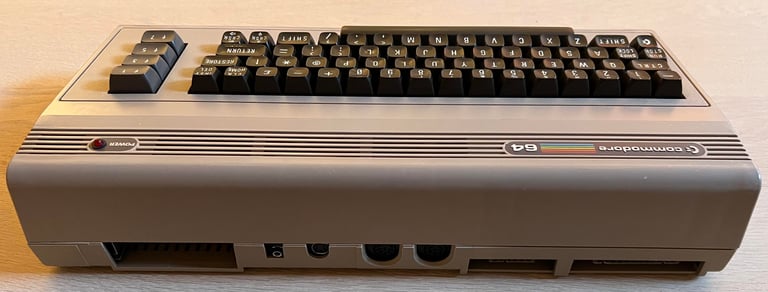
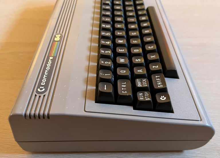
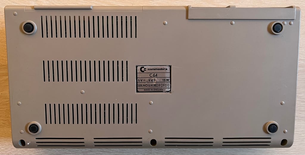
C64 Breadbin [PAL]
Ser. No. 1302816
Assy 250407
Artwork 251137 (REV B)
Starting point
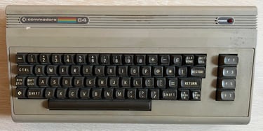
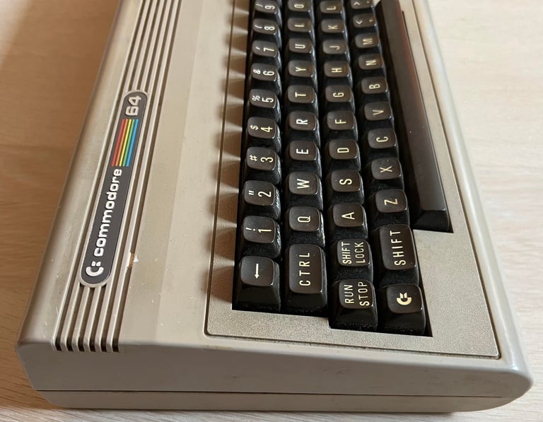
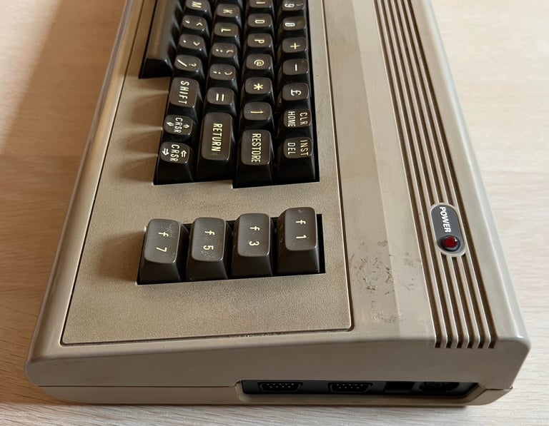
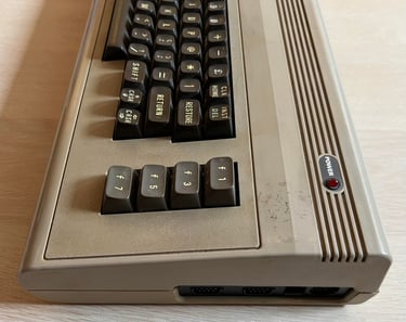
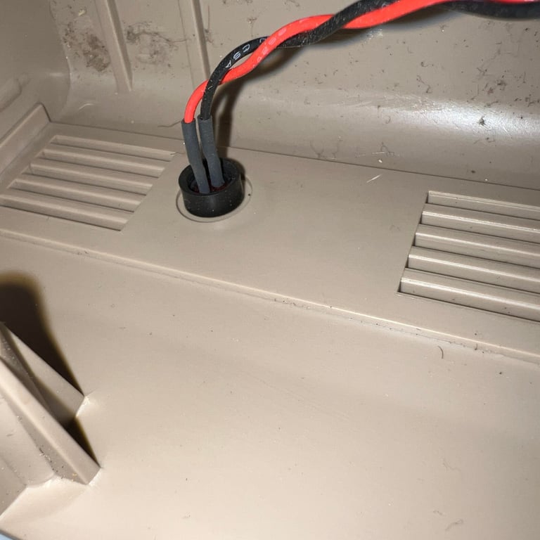
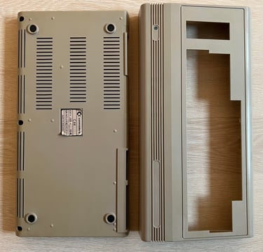
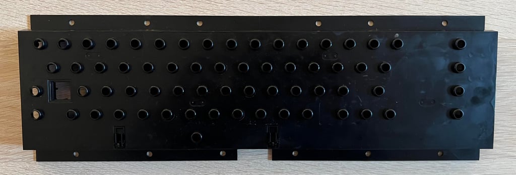
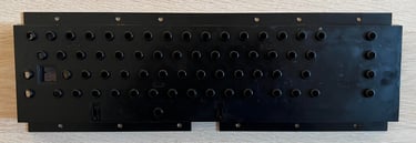
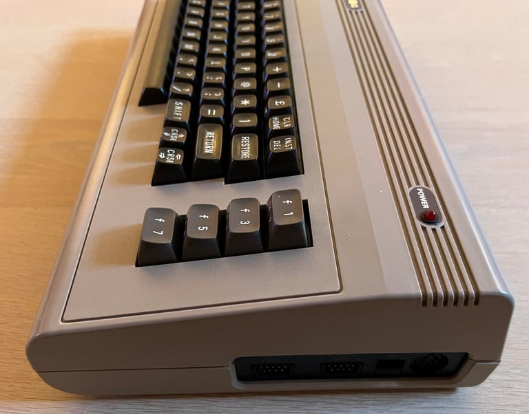
This machine is very dirty. There is a lot of grease and dirt all over the machine (I do not think the pictures does it justice - there is more than the eye can see). Even within the pores of the textures there is a lot of dirt. Also, the pictures does not show it too well, but it seems like the right corner of the bottom and top cover are not flush. I do think that this could be due that there are two screws at the bottom which are missing.
I have no idea if this machine is working or not - I will check that later. But if I look past the dirt and grease the machine appears to be in quite good condition. A lot of patience and hard work is required to get this machine refurbished, but I have high hopes that this will be a nice one.


Refurbishment plan
The refurbishment plan for this C64 breadbin (several of them in parallell):
- Refurbish the casing (cleaning, repairing and retrobrighting)
- Refurbish the keyboard (cleaning, reviving the plungers and retrobrighting)
- Refurbish main board (cleaning, checking, repairing, replacing capacitors and voltage regulators, adding heat sinks etc.)
- Replace the old RF-modulator with a modern RF-modulator replacement design by "The Retro Channel"
- Verify operation by testing
The plan can be updated during the refurbishment process. Sometimes I discover areas that needs special attention.
Disassembly
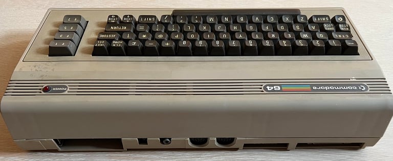
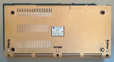
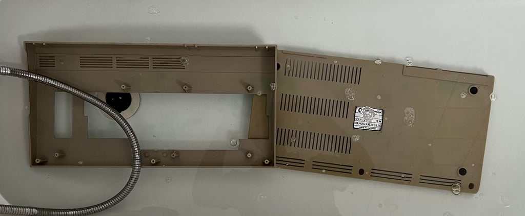
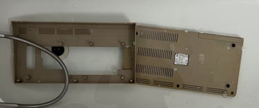
The Commodore 64 breadbin casing consists of a top- and bottom cover held together by rear clips and three screws - usually. But in this case only one screw is holding the two pieces together. This makes it very easy to open the machine, but I need to replace the missing two screws later.

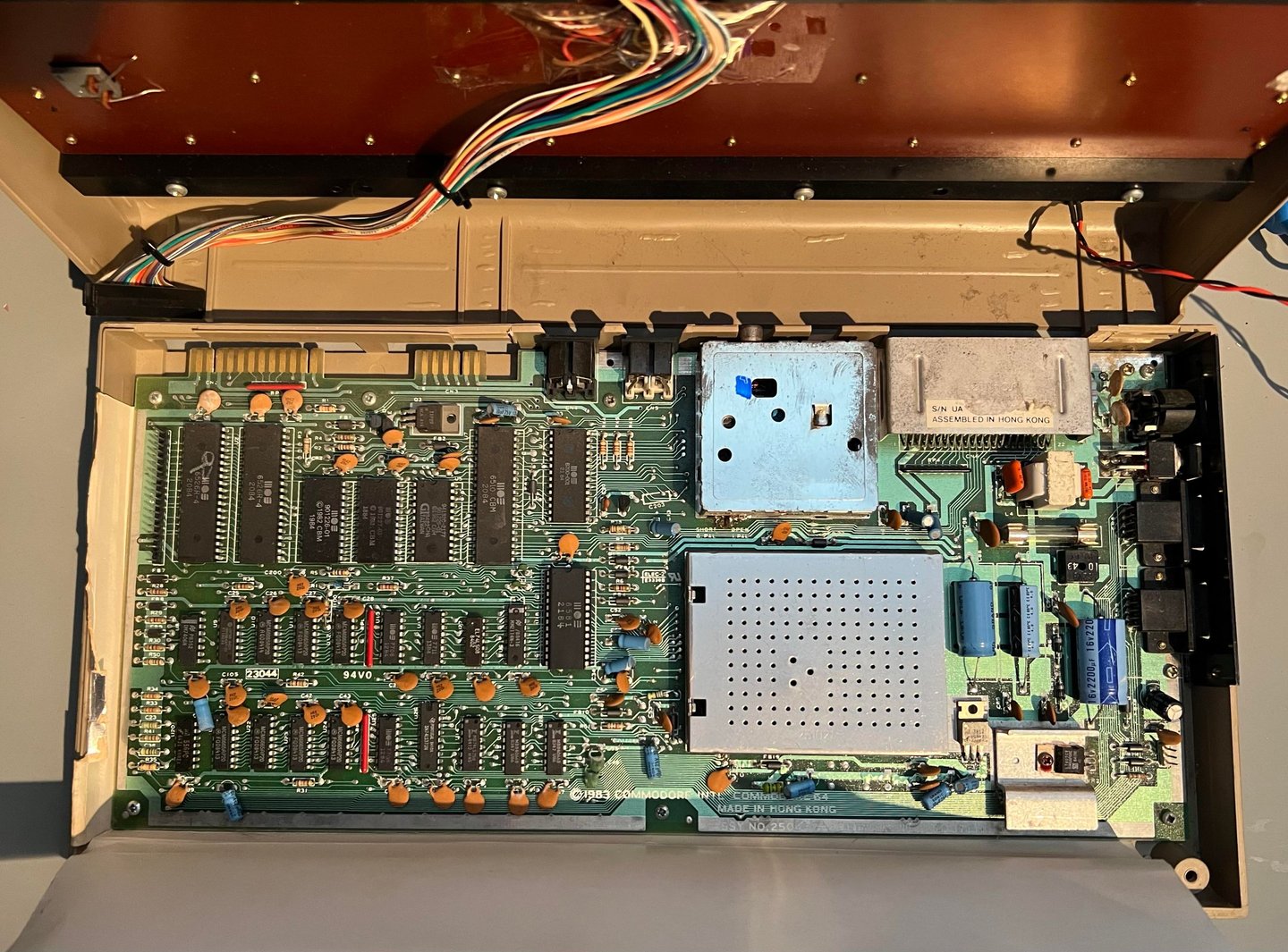
To separate the top from the bottom cover the top is lifted about 30 degrees, and then carefully wiggled back and forth until it is loose. This reveals the inside of the machine - and it looks very nice - the cardboard RF-shield shows no sign of any moist or damage. This shield will be discarded, but this is a good sign in regards what to expect to see on the mainboard next.
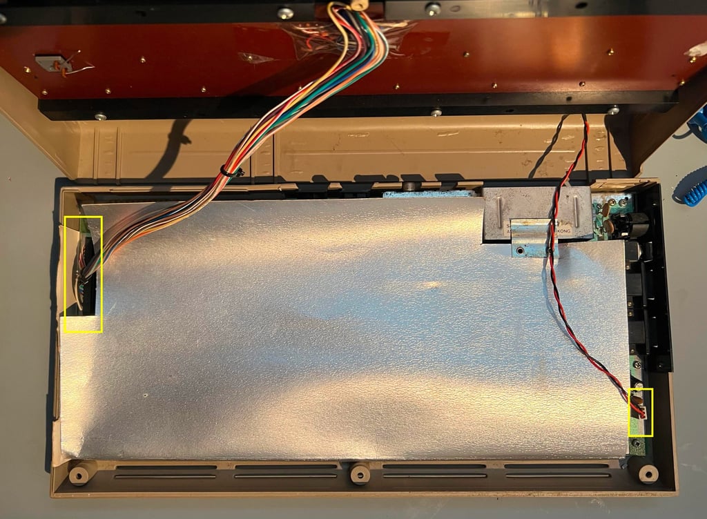

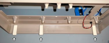
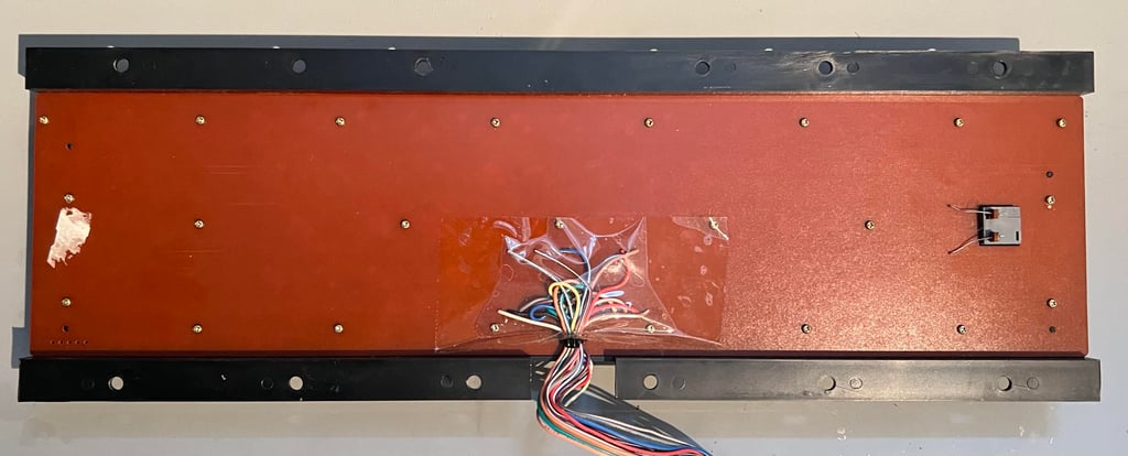
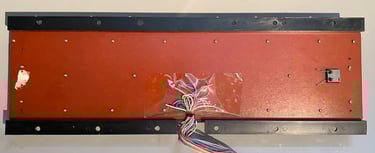
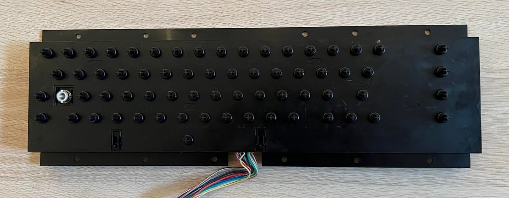
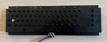
The LED- and keyboard connector are removed (see yellow squares above) and the RF-shield is lifted away. The PCBA mainboard is now revealed. It looks to be without any damage and corrosion, but there is a significant amount of dust and grease.
The PCBA mainboard is lossened from the bottom cover by removing the seven screws holding it place.
Exterior casing
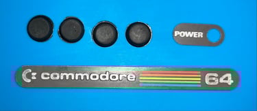
As mentioned the casing is really - REALLY - dirty. There is a lot of dirt, grease and sticker residue all around both the top- and bottom cover. The keyboard is removed from the top cover (eight screws). In addition the two metal badges (the COMMODORE 64 and POWER badge) are removed together with the four rubber feets. The reason for removing these is to avoid any damage during cleaning and/or retrobrighting (the rubber feets will be "mushy" during retobrighting if not removed). I try to carefully remove the sticker label at the bottom cover, but I fail to do so. Instead I leave it on hoping it will survive the cleaning and retrobrighting.
There are three clips on the rear of the top covers, and several of these are damaged/broken. This is very common on these old breadbins, but to fix this I will add some 3D printed plastic clips to replace these.
The badges and rubber feets are cleaned properly with mild soap water first and then some isopropanol. See picture below of the badges and rubber feets after cleaning.

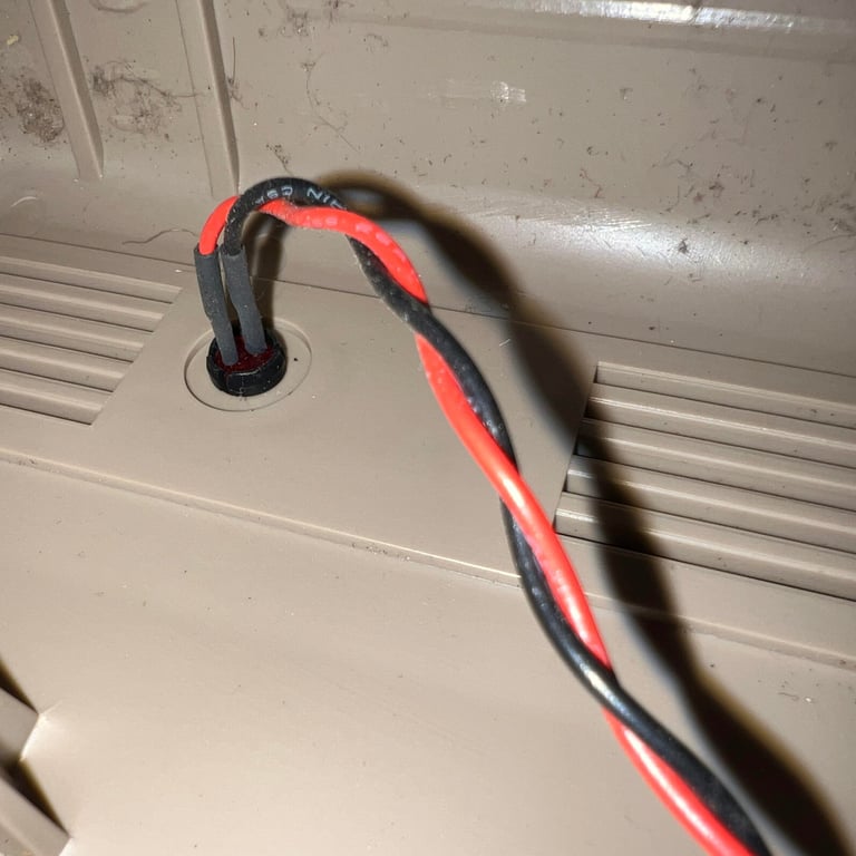
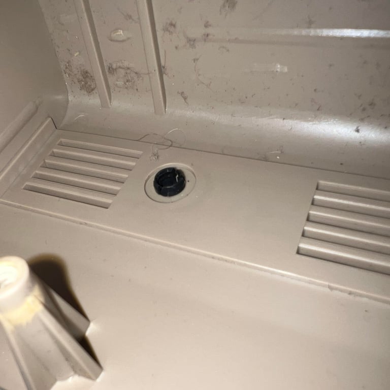
Before the badges were removed the LED was also disassembled. It is easy to remove the LED, but it can help to do it in the right steps; first the small circular ring is removed. Then the LED is pushed out of the plastic clip by applying a firm press from the outside towards the inside of the cover. The LED will pop out, and the plastic clip can be pushed out from the backside of the cover towards the front. See small gallery below.
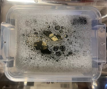
The top- and bottom cover is placed in mild soap water for about 48 hours. This will remove most of the dirt and grease which is crucial for a successful retrobright.
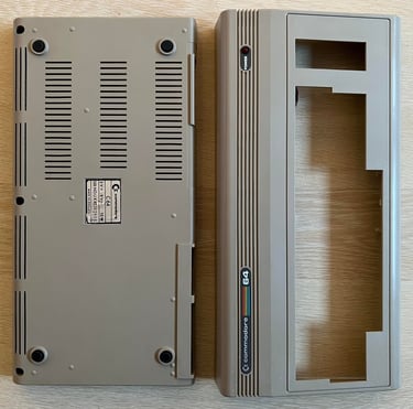
After the bath the covers are look way better. There are still some marks and residue from stickers. These are removed with isopropanol, and finally the covers are cleaned once more with mild soap water. The result from cleaning can be seen below.

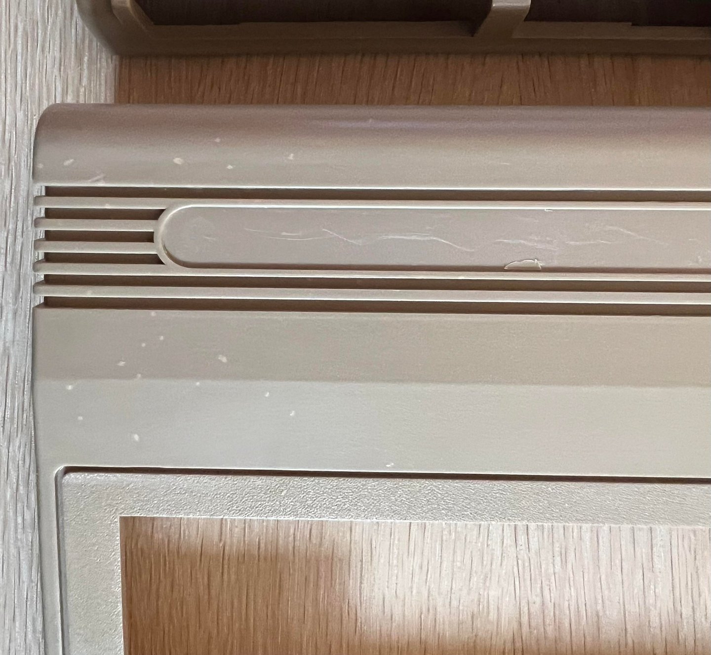
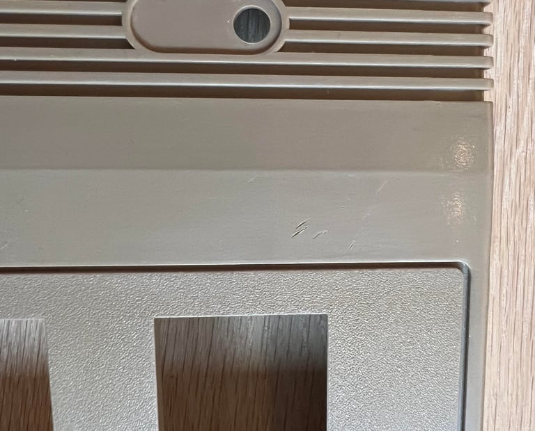
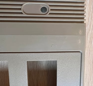
There are some strange spots/marks which I do not manage to remove. I was thinking of sanding them, but I think that the grooves are too deep. So I decide to leave them for now. See pictures below.

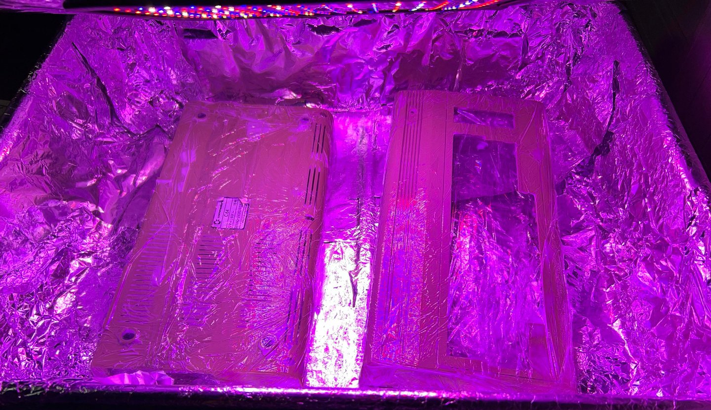
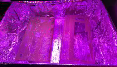
Both top- and bottom cover are covered with 12 % hydroperoxide cream, wrapped in cling film and exposed for UV light for about 12 hours. About every hour fresh hydroperoxide cream is applied to the covers to make sure the cream does not dry up.
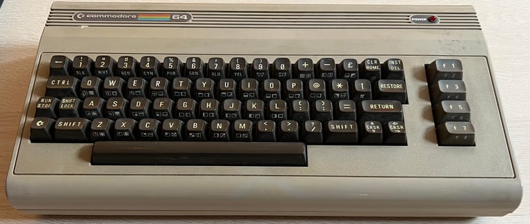
The result from the cleaning and retrobrighting is quite good. There are still some small spots (?) and marks which is not possible to remove without sanding the whole casing, but I do not think that is a good idea. You can notice it in the area to the left side and below the Commodore 64 badge. It is better to keep it the way it is.

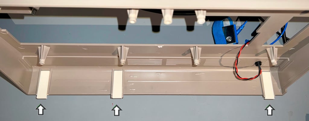
Some of the rear plastic clips are broken (which is very common on the breadbin). Although it is not strictly required to fix this, it is good practice to do so. Some 3D printed plastic brackets are glued in correct position. In fact, these 3D printed plastic clips will probably be way better than the original ones. I use these for refurbishment: https://www.thingiverse.com/thing:5916458
Keyboard
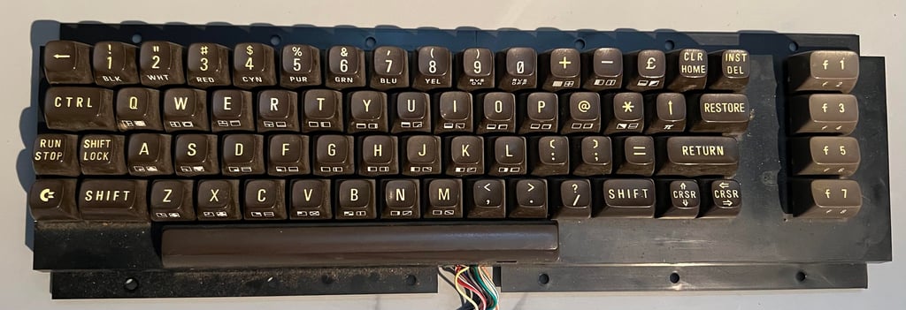
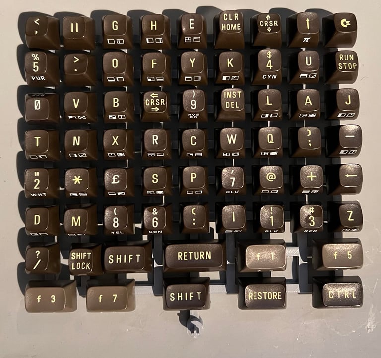
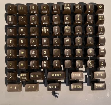
Not bad! I have refurbished quite a few Commodore 64 keyboards, but this is one of the better looking. There are of course some dust and grease, but apart from that it looks to be in very good condition. Nevertheless, I will do a complete refurbish of the keyboard.
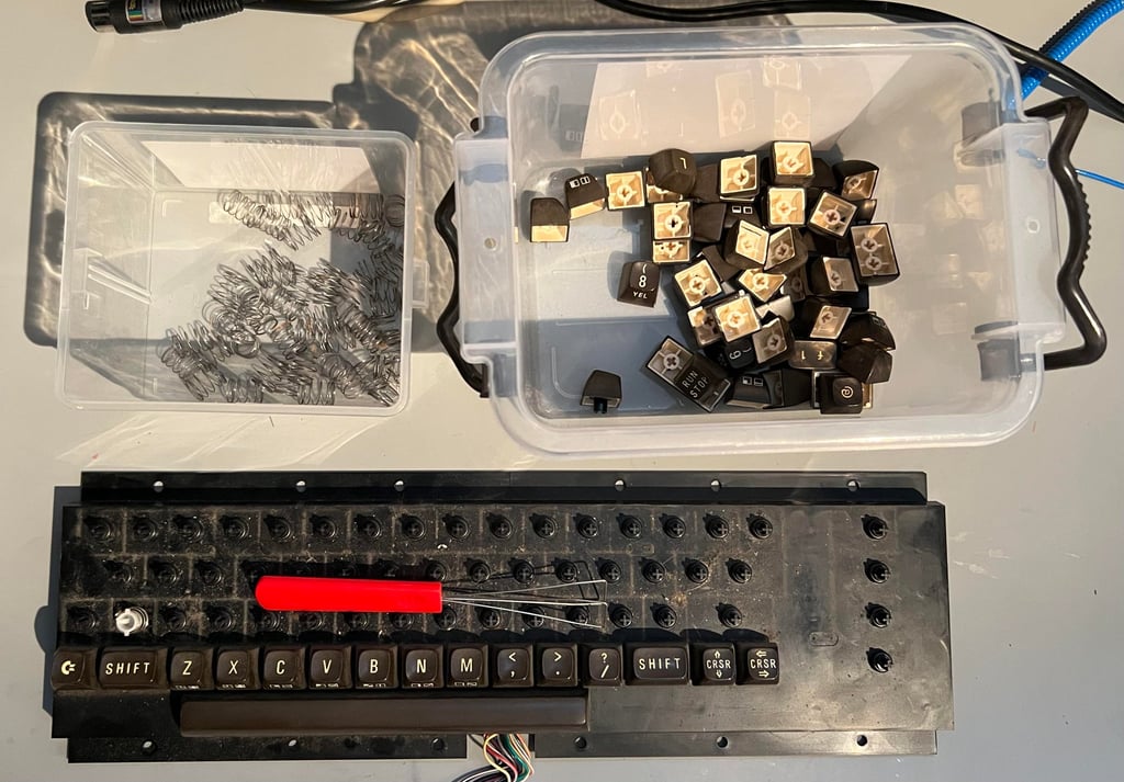
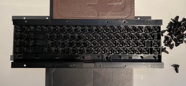
All the keycaps are removed using a special keycap puller. This is highly recommended to avoid any damage to plungers or keycaps (or your fingers for that matter). Note that there is a spring beneath each keycap, and that the spring beneath the spacebar is slightly taller than the other springs - so it is good practice to keep this spring separately from the rest.

To disassemble the keyboard PCB (which is the backside of the keyboard) all the 23 small screws are removed. Tip: when re-assembling the keyboard later it is good practice to turn the screws counter-clockwise until it "clicks into place" before tightening. This will reduce the risk of damaging the plastic holder screws.
Next the SHIFT-LOCK key is removed. First, the two uninsulated wires are desoldered. Then the SHIFT-LOCK key is pushed firmly from the backside towards the front side until it pops out.

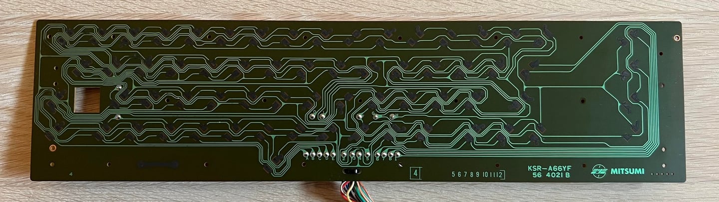
All of the 23 screws at the backside are removed which then releases the keyboard PCB. This is the Mitsumi KSR-A66YF 56 4021 B keyboard PCB with the carbon pads (the last "B" in the version number indicates this). The PCB is cleaned thoroughly with pure distilled water. I use this instead of isopropanol since this can damage the carbon pads. Below is a picture of the keyboard PCB after cleaning.
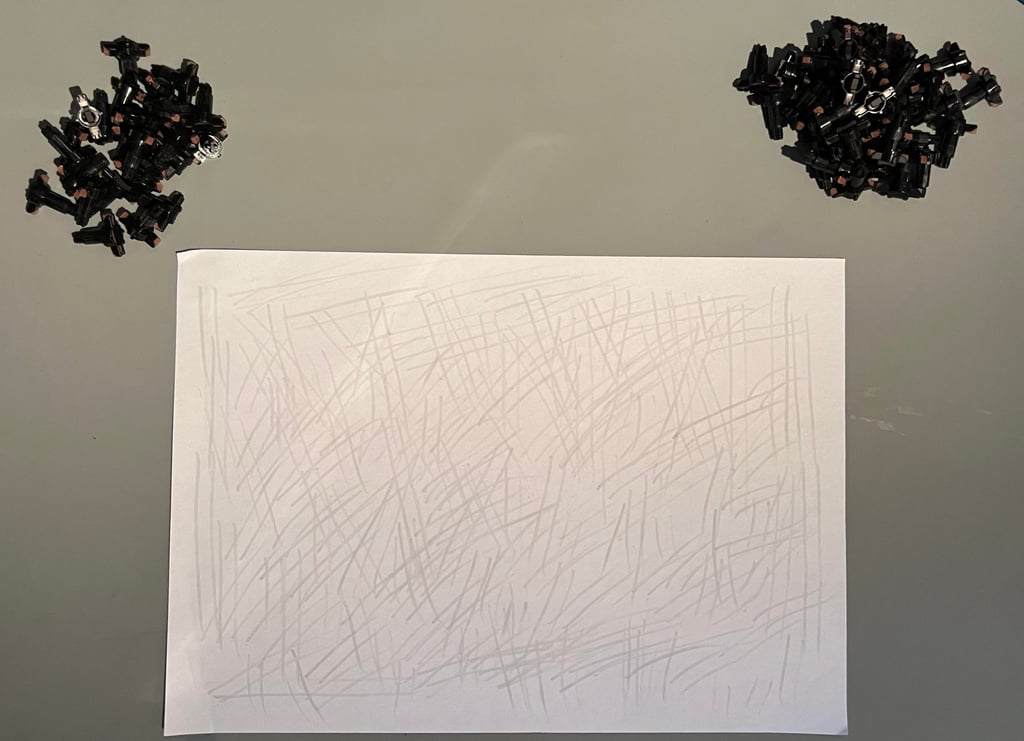
After 40 years the conductive rubber at the end of the plungers are covered with dust and grease. This will prevent the keyboard from proper operation as the user need to press the keys very hard to get any registered response. Luckily, this can most often be fixed quite easily. By carefully "rubbing the rubber" over a clean sheet of paper most of the grease and dust will be removed. Note that you need to be gentle with this operation to not damage the plungers.

The plastic holder is cleaned properly with mild soap water and a soft paint brush. Looks good as new!
To make sure that the keycaps are free from grease and fat before retrobrighting they are placed in a box filled with mild soap water for about 48 hours. This will dissolve most (all?) of the grease which is essential for a successful retrobrighting.

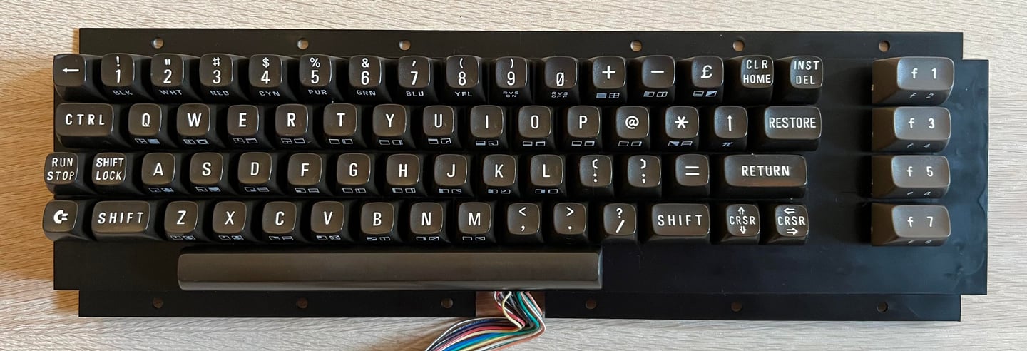
When re-assembling the keyboard the plastic holder is lifted from the table by using a few books. This will make it way easier to refit all the plungers and then mount the PCB back in. As can be seen from the pictures below the keyboard looks now in very good condition.

The top letters of the keycaps are quite yellowed. Compared to the symbols on the side of the keycaps (which are not yellowed) the top letters are way more yellowed. All the cleaned keycaps are placed on the 3D printed keycap mount, and then the keys are smeared with 12 % hydrogen peroxide cream regularly (about evey hour) while being exposed to UV light.
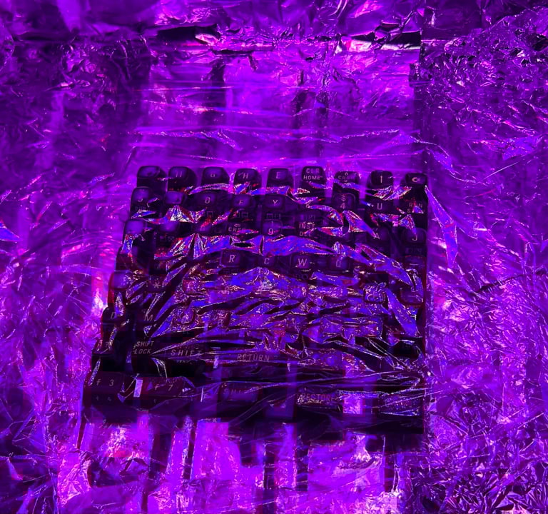
After retrobrighting the keycaps looks way better. They are not perfectly white, but most of the yellowing is gone. Below is a picture of the reassembled keyboard - it looks really good.
Mainboard
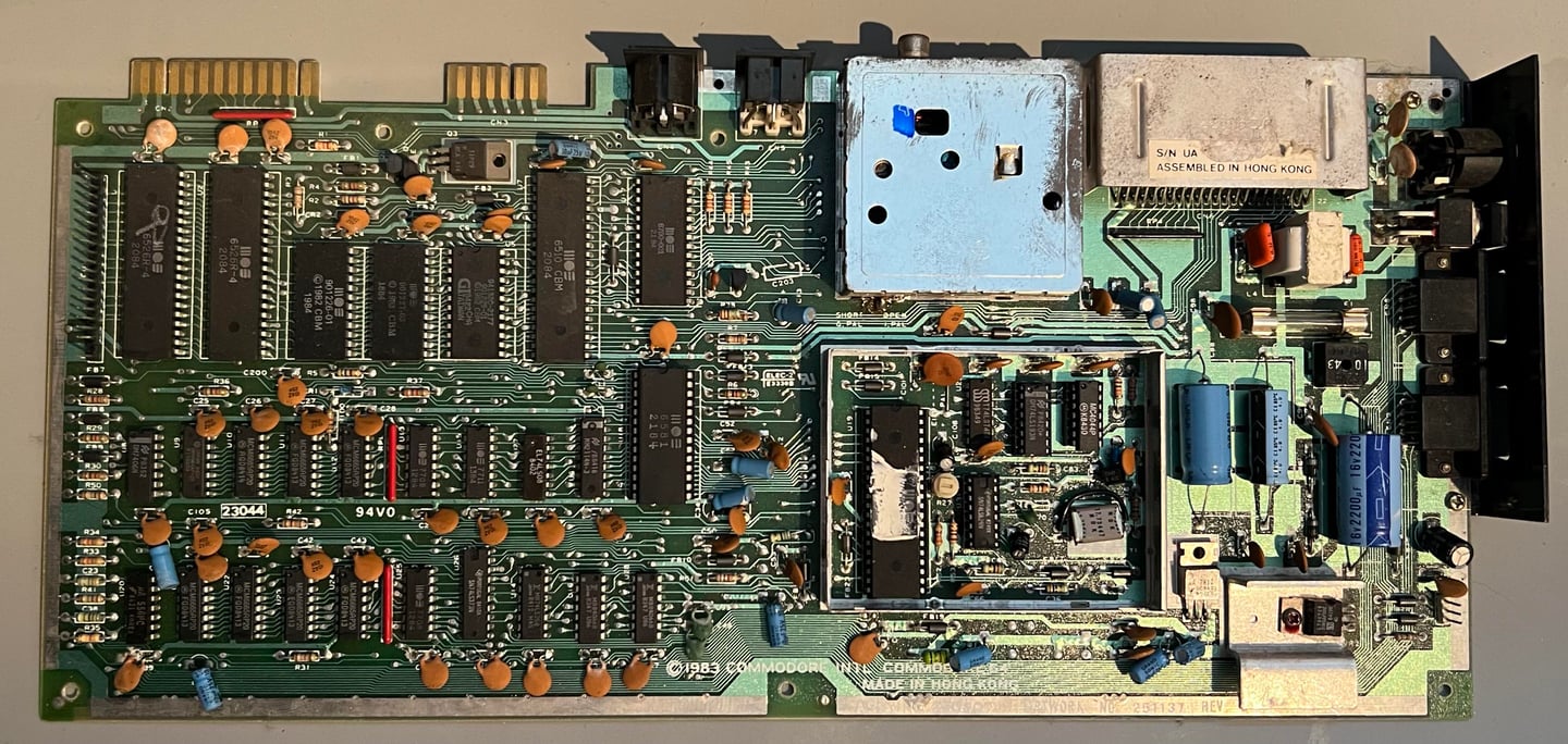
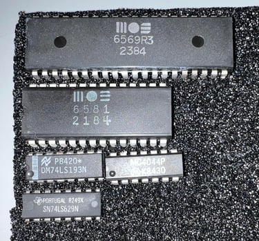
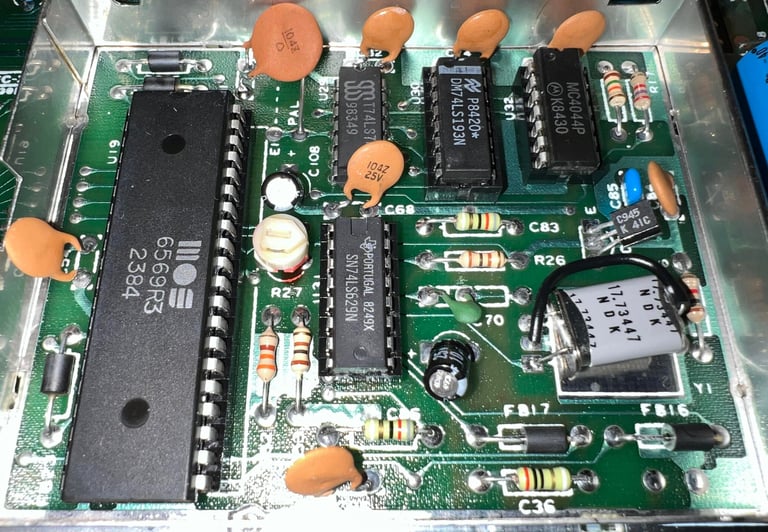
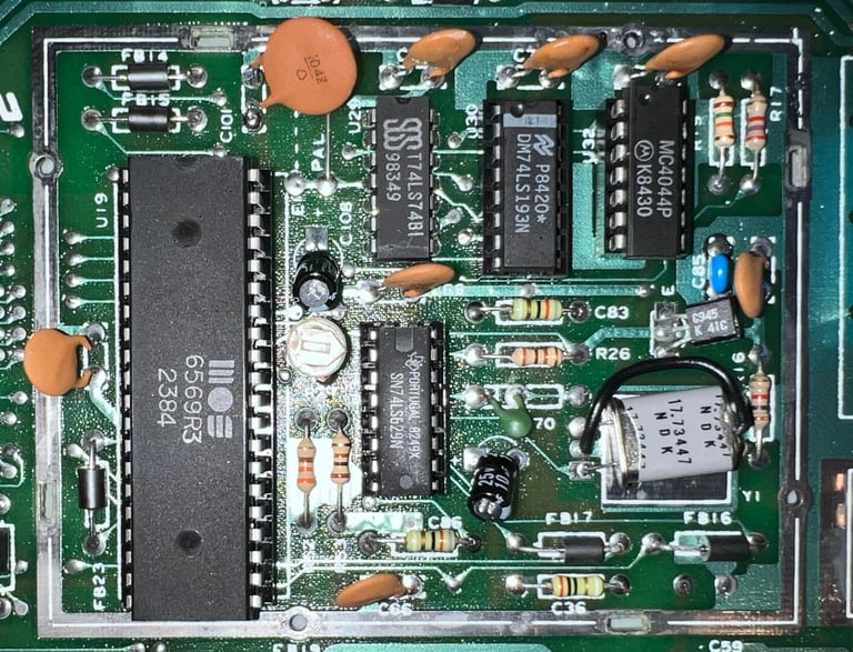
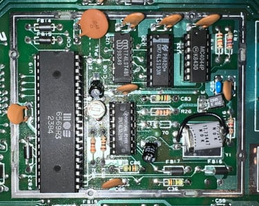
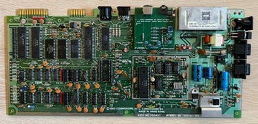
This PCBA mainboard version is assy 250407 artwork 251137 (Rev 3B) commonly found in Commodore 64 breadbins. With the VIC-II area RF-metal shield out of the way all the ICs on the mainboard are exposed. Only two of the custom chips are socketed: the MOS 6581 SID and MOS 6569 VIC-II (some of the glue logic making up the clock circuitry are socketed as well).
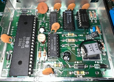
The mainboard looks to be undamaged, and I can not see any immediate signs of corrosion or rework.

Before starting with further inspection and testing the mainboard needs to be cleaned. Not because this is strictly required, but it working with a clean mainboard is both more nice and makes it easier to detect any physical damage. To clean the mainboard is simple using plenty of clean water and some mild soap together with a soft paint brush. Note: before the cleaning the fuse and all the socketed chips are removed. The tools used is a chip lifter and a chip extractor. See picture below.
Visual inspection
The mainboard appears to be in good general condition. I can not see any sign of damage, corrosion or rework. Nevertheless there are some things I notice:
Three of the ICs in the VIC-II area used for the clock circuitry are socketed. This appears to be from factory, but I do not think this is common.
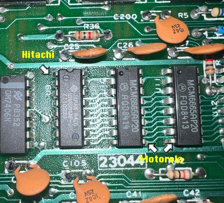
1 out of 8 RAM ICs are from Hitachi and the rest from Motorola. This is normal. Commodore used whatever chips they had available at production time.
There are three MOS 77xx ICs used for glue logic. These are notorious for failing so I will replace these even if they work (now).
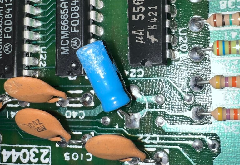
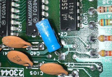
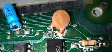
One of the ceramic capacitors looks a bit... odd? Is probably ok, but needs to be checked
Two of the electrolytic capacitors appears to have suffered from some kind of dissolving (?) The outer covers are partly broken and the covers feel strange to touch
The ON/OFF switch appers to be working, but it feels a bit stiff. Need to look into that one.


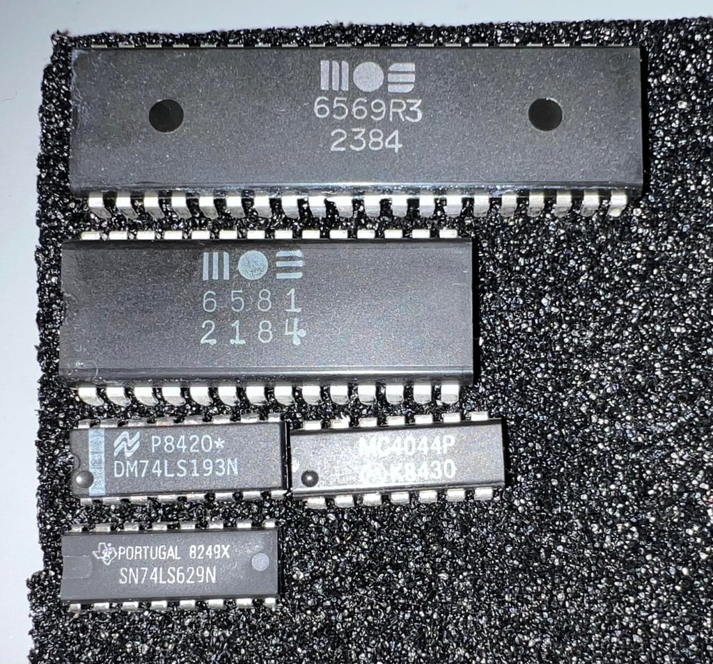
In the table below all the custom ICs are listed. And as can be seen from this table is that all ICs were produced between week 18 to 23 of 1984 so I think we can assume that this Commodore 64 was produced in the summer, or early autumn, of 1984.
Checking the voltages
For the Commodore 64 to work flawlessly all the different voltages need to present and within acceptable tolerances. The 5V at the user port is a bit low, but I think that is due to the power supply or the power switch. A detailed article on the subject can be found in the HOWTO - Checking the C64 voltages. In the table below all the measures voltages are listed (this list will also be updated after refurbishment). All the required voltages are present and within tolerances, so there are nothing obvious wrong in that area. NOTE: for those who follow my refurbish project you may notice that many of the voltages appear lower than seen before. The voltages are completely fine, but I am now using a modified C128 PSU which outputs a bit lower voltages - but it is well within tolerances.
Initial testing
Before the machine is powered on for the first time a check for short circuit on the +5V DC and 9 V AC power rail is performed. This is easy to check at the user port – see the article of Checking the C64 voltages for the position of these. Luckily, there are no short circuit so it should be safe to power on.
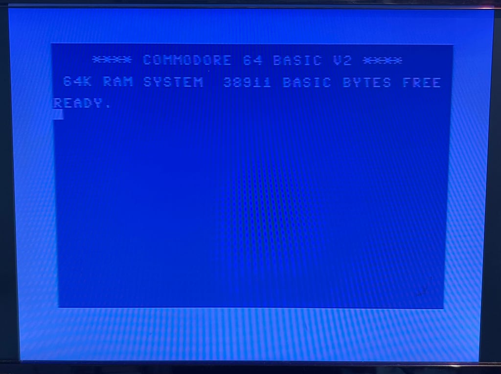
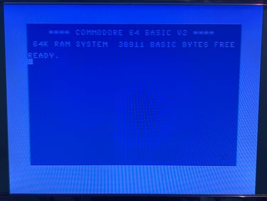
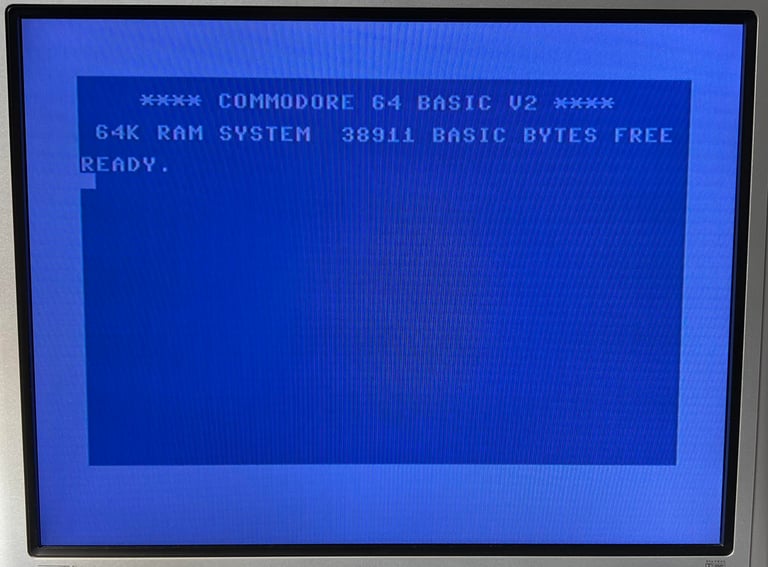
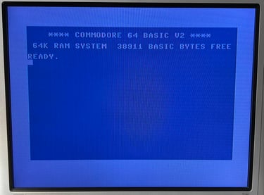
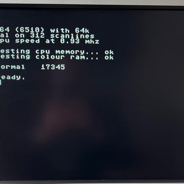
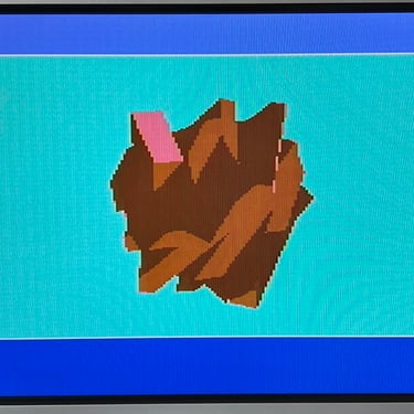
Powering on the Commodore 64 results in a: NORMAL BLUE BOOTUP SCREEN.
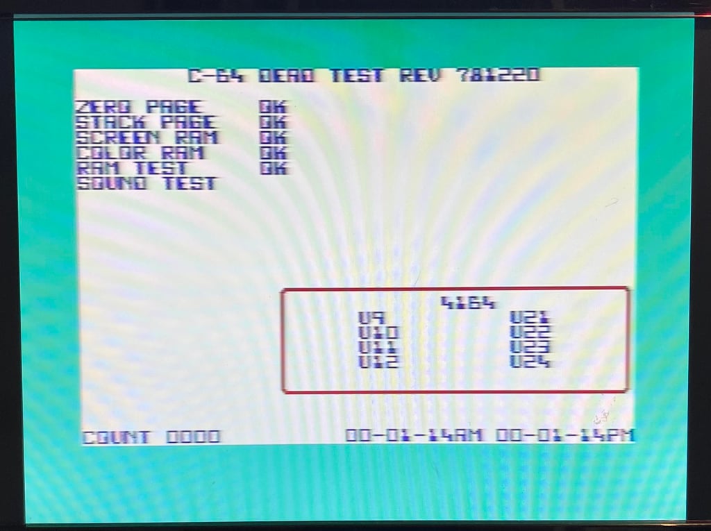
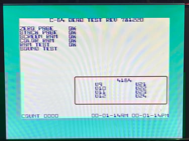
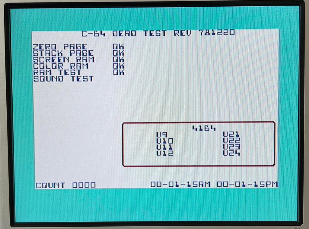
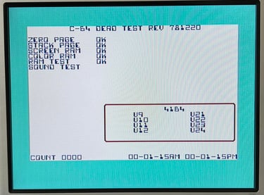
Next step in the initial testing is a test run with the Dead Test Cartridge. This will not reveal more complex issues, but it gives a good initial test of the major custom ICs. No errors were detected using the Dead Test Cartridge.
Removing the VIC-II RF-shield
The VIC-II is one of the warmest ICs on the mainboard. To avoid excessive heat building up inside the VIC-II RF-shield, the whole cage is removed. Heat sinks will be added on the VIC-II later. You could argue that electromagnetic interference could disturb the analog video signals, or the VIC-II in general, but I think that there is a greater probability that the VIC-II will fail due to heating than to electromagnetic interference.

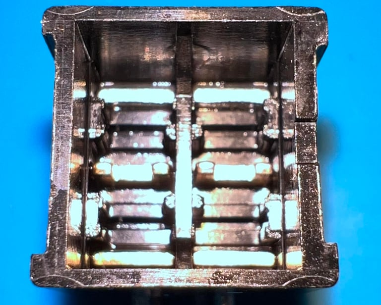
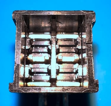
Cleaning the power switch
As mentioned the power switch feels a bit stiff. And I do suspect that there is a small voltage drop lost in the switch due to dirt and grease inside it. So the power switch is desoldered from the mainboard. To do this I use a combination of tools such as soldering iron, desoldering gun and some hot air. The power switch is desoldered without any damage to traces or pads.
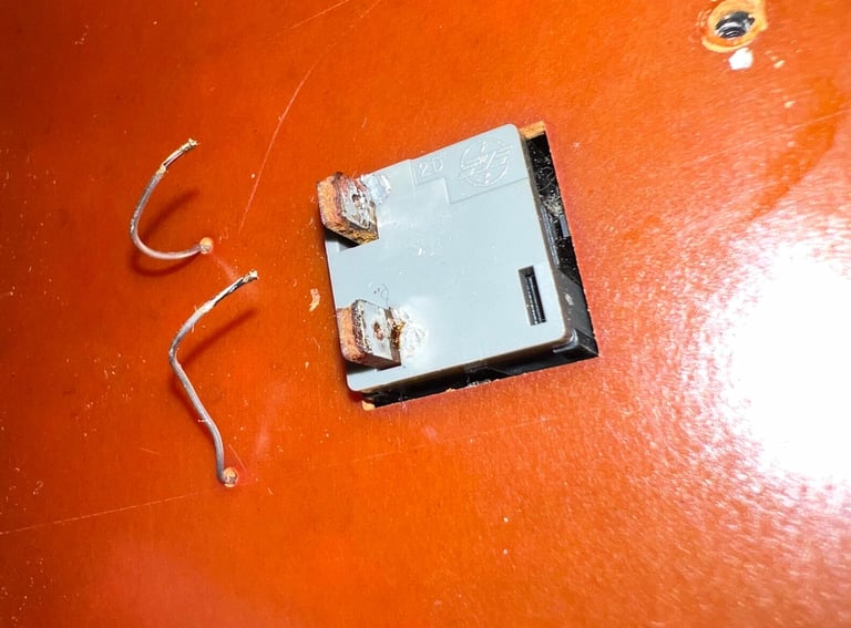
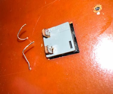
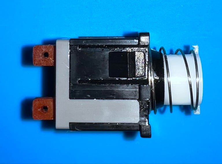
The power switch itself is also undamaged after the desoldering. I can not see any immediate signs on the outside indicating any problems with it - so it needs to be opened.

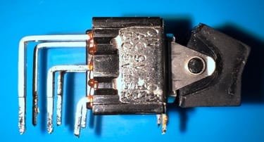
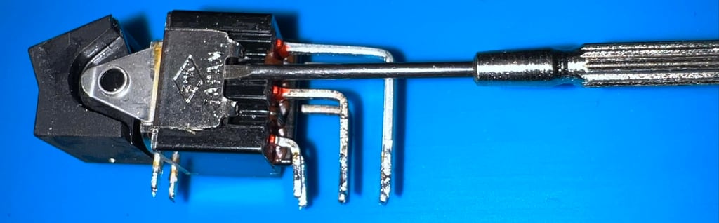
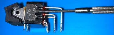
Opening the power switch is not difficult, but it can be a bit fiddly due to small parts inside the switch. A small thin and flat screwdriver is used to carefully pry the switch open.
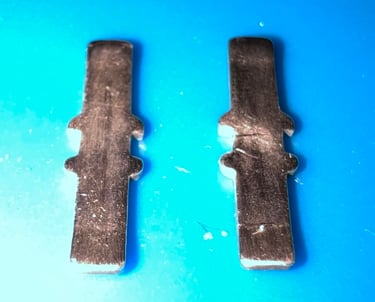
The two small metal plates (looking like skis?) are cleaned properly with a glass fibre pen and isopropanol on a Q-tip. After the cleaning the metal plates looks way better. All the dirt, crease and oxidation is gone. In addition the metal contacts within the plastic container is also cleaned properly with isopropanol.

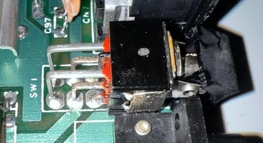
The power switch is soldered back in and tested. It works much better. It is still a bit stiff, but way better than before. I think the reason for the stiffness is that the plastic housing is a bit tight and there is not too much to do with that. There is a smal voltage increase at the 5VDV rail at the user port. Not so much as I hoped for, but still some. The 5VDC voltage level was 4.772 V before the power switch cleaning, and now the voltage is 4.791 V. In the picture below the refurbished power switch is soldered back in. Note that the right hand side (seen from above) appears not to be fully closed. But I think that the pressure is so tight that the switch will stay in place. Pressing it harder can make it break I am afraid.

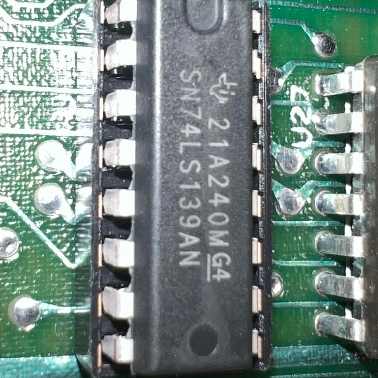
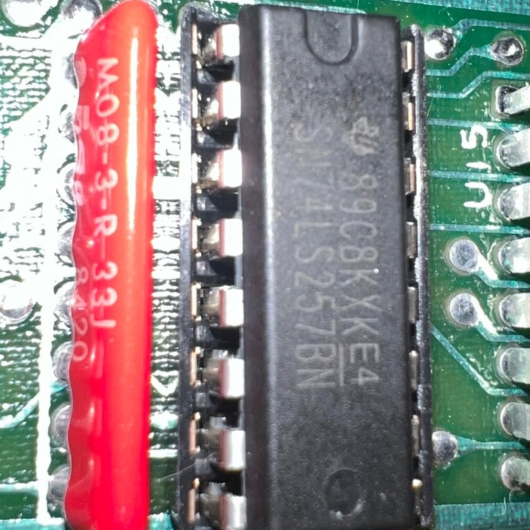
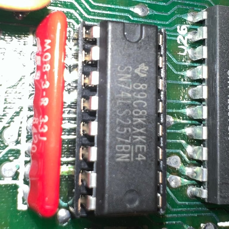
Replacing the MOS 77xx
As previously mentioned there are some MOS 77xx glue logic here. These MOS 77xx are notorious for failing, but luckily these are possible to replace with modern ICs. Below is the list of MOS 77xx used in this mainboard and the replacement IC:
2 x MOS 7708 @ U25, U13 equivalent with 74LS257B (Quadruple 2-line to 1-line data selector / multiplexer)
1 x MOS 7711 @ U15, equivalent with 74LS139A (Dual 2-line to 4-line decoder / demultiplexer)
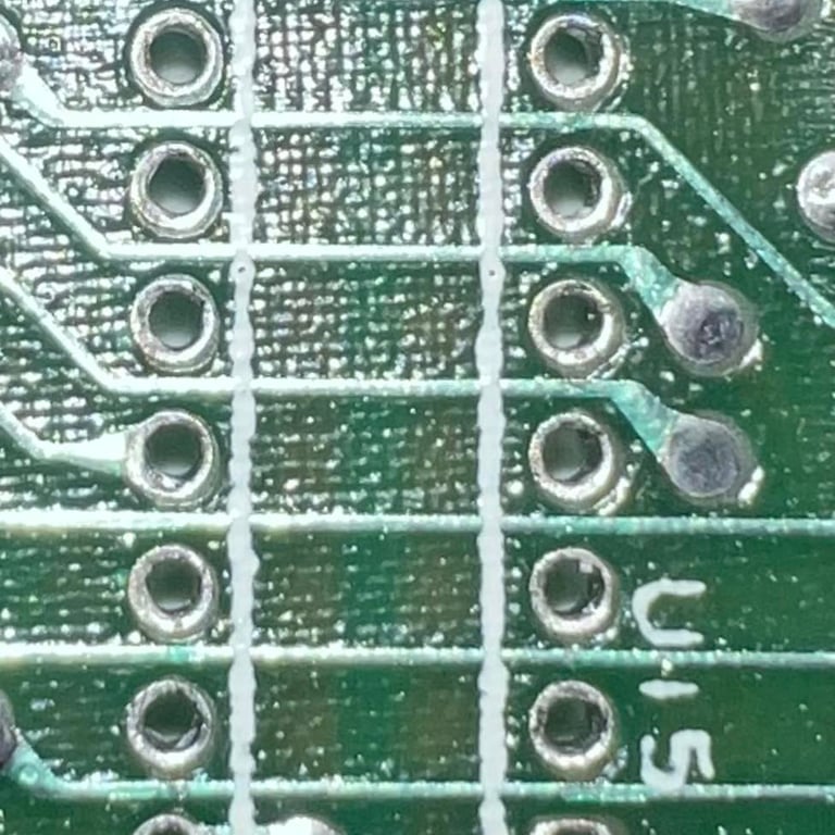
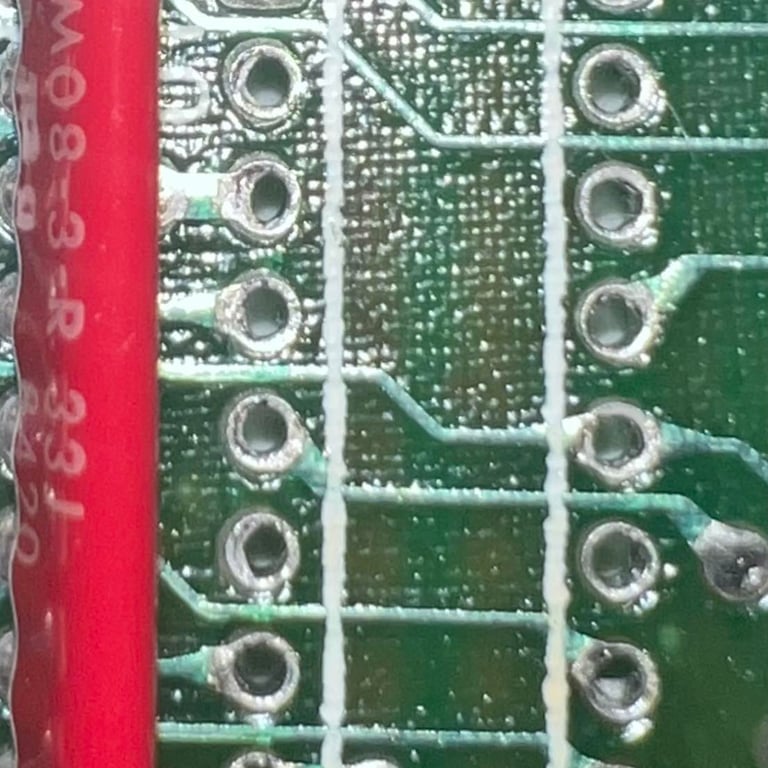
The IC at U13, U15 and U25 are desoldered without any damage to traces or pads. Sockets are installed and new modern ICs (2 x 74LS247B and 1 x 74LS139A) are installed. See picture gallery below.
Replacing the 78xx voltage regulators
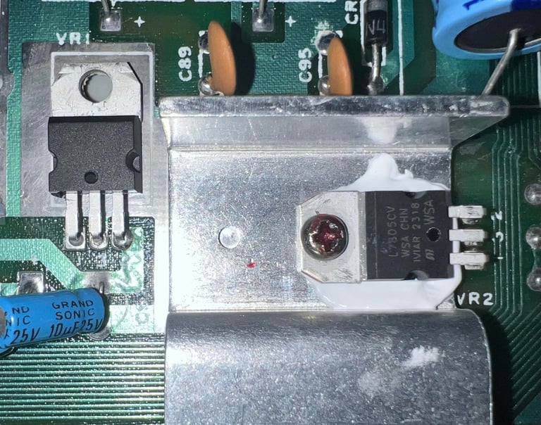
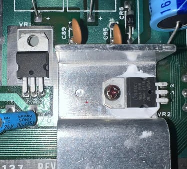
It is good practice to replace the on-board 7805 and 7812 voltage regulators for the 5 VDC and 12 VDC respectively. You can read about the purpose of these regulators in the HOWTO - Checking the Commodore 64 voltages article. But in short; these voltage regulators generate the 5 VDC and 12 VDC, used by the MOS 6569 VIC-II and MOS 6581 SID chip, sourced by the rectified 9 VAC from the PSU.
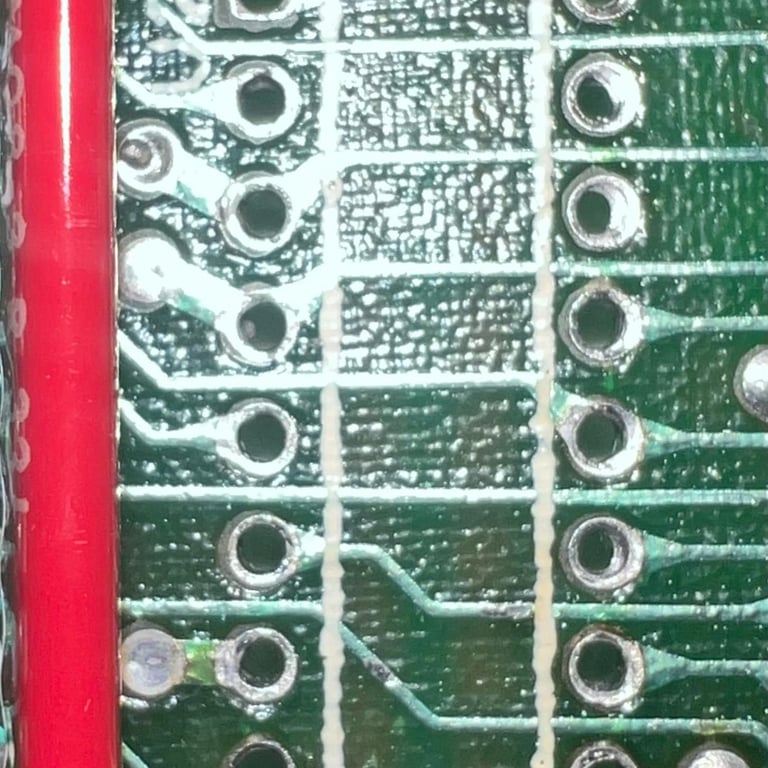
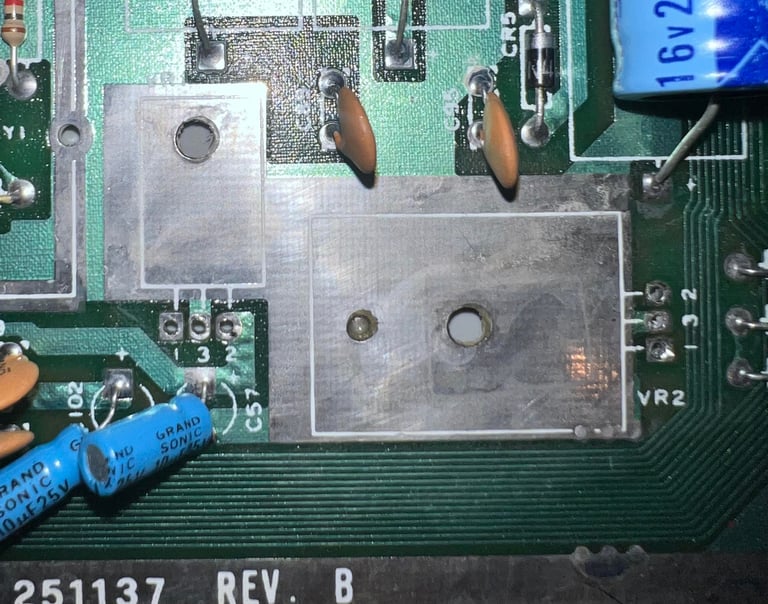
The old 7805 and 7812 voltage regulators are desoldered without any damage to traces or pads. Note that only the 7805 voltage regulator is mounted on a heatsink - this is normal from factory. Below is are som pictures from the replacement process.

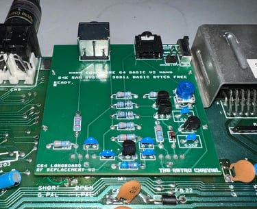
Replacing the RF-modulator
From The Retro Channel:
"The RF modulator in the C64 handles amplification and filtering for all video signals (including the ones on the C64 DIN connector). Unfortunately it does a very poor job and this is even more apparent with modern displays and upscalers, even CRTs with their inherent softening can reveal issues with the original RF modulator. One way to signifcantly improve the video output is to replace the RF modulator with a more modern and finely tuned solution, and why not add a few quality of life features while were at it."
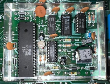
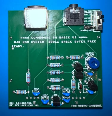
The Retro Channels have designed what is probably the best analog RF-modulator available. And the design is open-source. I order the PCB from PCBWay and components are ordered from Mouser Electronics. Below is a picture of the fully assembled RF-modulator replacement.
NOTE: There is a 500 Ohm potentiometer which can be used to fine tune / adjust the video signal when in operation. Please check the The Retro Channels GitHub site for more details.

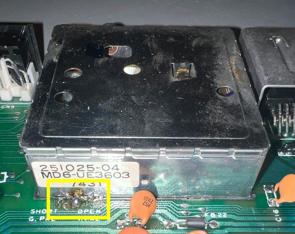
To install the new RF-modulator replacement the old RF-modulator needs to be desoldered and removed first. But I notice that there is a large blob of solder between the RF-modulator shield and the mainboard. Desoldering the RF-modulator is not trivial even without with this extra solder blob so this will be an extra challenge. Please see the HOWTO article "Desoldering the RF-modulator" for detailed information on how I desolder the modulator in general.
In the picture below the old RF-modulator is shown with the large solder blob (see yellow square).

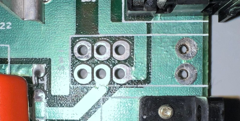
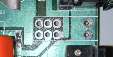
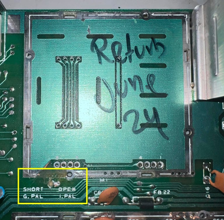
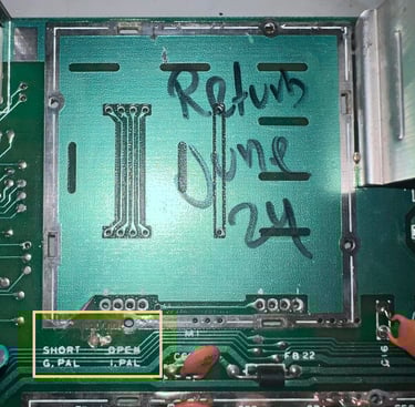
The RF-modulator is desoldered, but a part of the shielding trace is broken. Note that this is not an important trace since this is only connecting the shield to this trace, but this trace is connected to a jumper setting "G.PAL / I.PAL" which needs to be repaired. This jumper was SHORT (closed) setting the RF-modulator in "I.PAL" mode before desoldering. Below is a picture of the desoldered area. Note that all the important pads / traces are undamaged, it is only the "G.PAL/I.PAL" jumper and a small part of the shielding trace which are damaged. The yellowed squared area shows the damaged area.
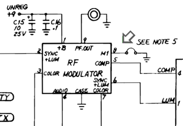
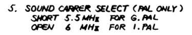
So what is "G.PAL" and "I.PAL"? According to the schematics this "G.PAL" and "I.PAL" is a jumper which connect the RF-modulator pin #8 to ground when shorted. See schematics below. As can be seen from the note #5 this will set the sound carrier to either 5.5 MHz (G.PAL) or 6.0 MHz (I.PAL) for the modulated RF-signal. Note that is only relevant if you use an old TV-set and the RF-input (not relevant for S-video or composite). G.PAL were used most in Western Europe and I.PAL were used in the UK.
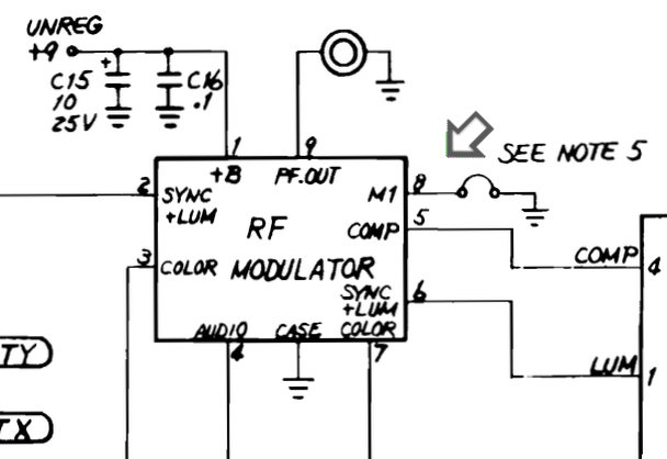

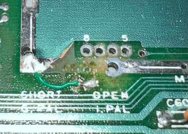
Living in Norway the "correct" jumper mode would probably be "G.PAL", but to replicate the original setting I choose to go for the "I.PAL" mode. To to this a small bodge wire is soldered from the shielding trace to the jumper. This will short pin #8 to ground. If the new owner of this machine at some time would like to go for "G.PAL" the bodge wire can be cut. See picture below for the bodge wire.

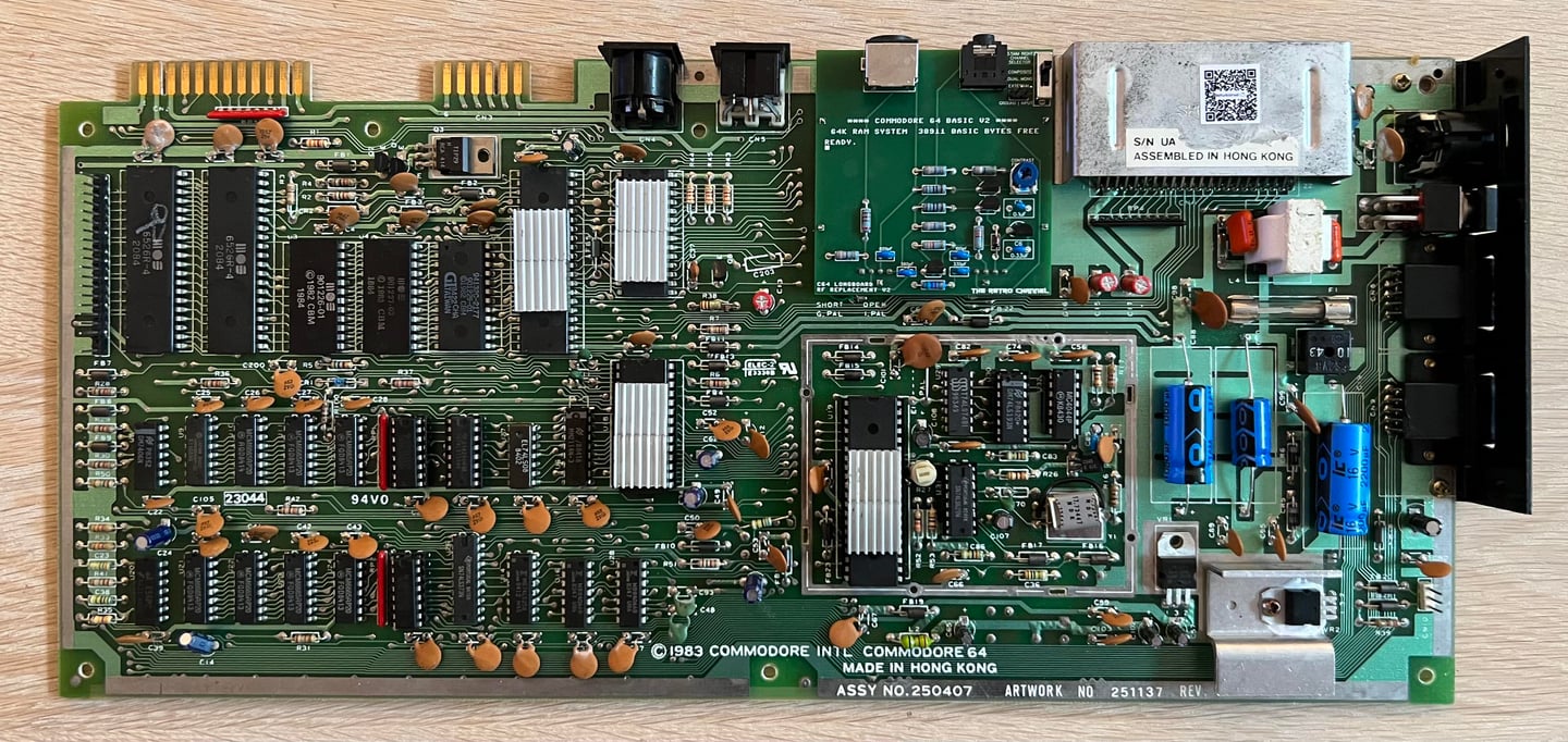
With the old RF-modulator out of the way and the bodge wire in place the RF-replacement modulator is soldered in. It looks very nice!

Replacing the electrolytic capacitors
According to the capacitor list there are 18 electrolytic capacitors on the Assy 250407 / Artwork 251137 Rev B mainboard. These capacitors are over 40 years old and are likely to have altered the capacity/ESR due to age. There are many opinions on whether or not it is necessary to re-cap a Commodore 64, but I think it is good practice to do so.
Below is a picture of the mainboard after the new capacitors are installed.

Adding heat sinks to custom ICs
Many of the old custom ICs run very hot. And heat can stress the ICs reducing the life span. Therefore it is good practice to add heat sinks on some of the "hottest-running" custom ICs: the SID-, VICII-, CPU- and PLA chip.
Below is a picture of the mainboard with the new heat sinks installed.

Testing
Proof is in the pudding - does it work?
Testing is done through two main stages:
Testing the basic functionality and chips
Testing by using the machine playing demos, games etc. accessed by both floppy and datasette to verify correct operation
Basic functionality and chips
First test is done using the Dead Test Cartridge. This test doesn´t test all the functionality of the Commodore 64, but it does test the basic functionality of the major chips such as the CIA #1/2, CPU, VIC-II, PLA, RAM and SID. As the picture shows below the test is passed.
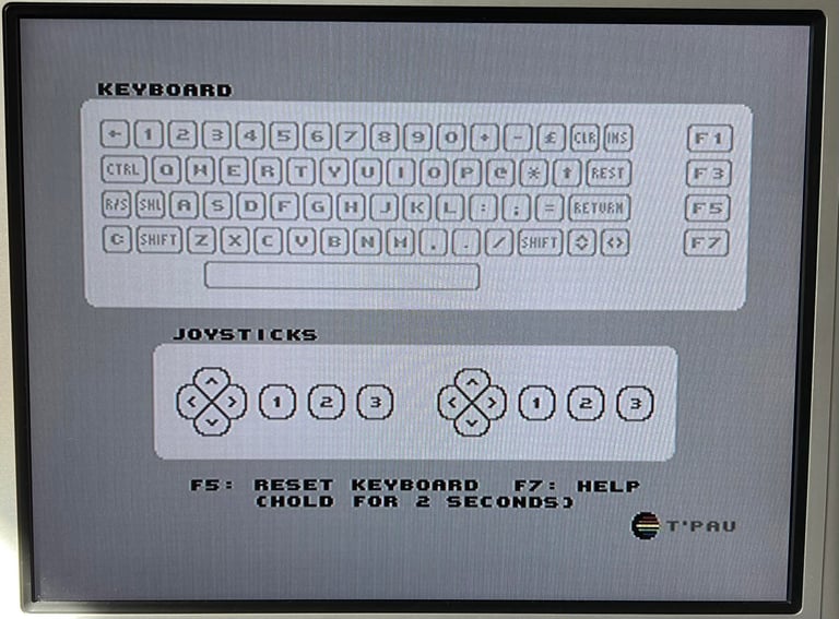
Next test is to power the Commodore 64 to the blue boot up screen and also check the keyboard to make sure all keys works as they should. The test is passed; all keys works and 38911 BASIC Bytes Free.

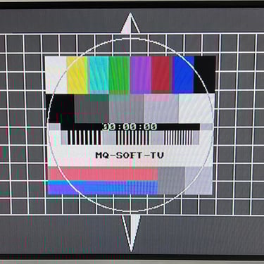
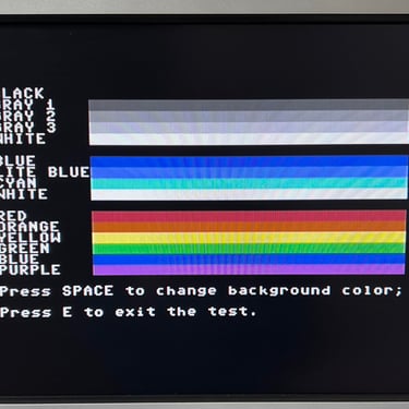
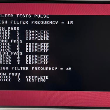
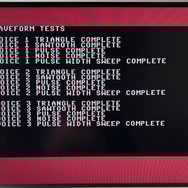
The basic functions of the VIC-II, SID and RAM is tested with 64 Doctor, Commodore 64 SID tester and MemTest64. Note that this is to be considered as basic functionality - more advanced (?) functionality such as sprite handling / collision detection / advanced audio will be tested later. But the basic tests pass without any detected faults (click to enlarge).
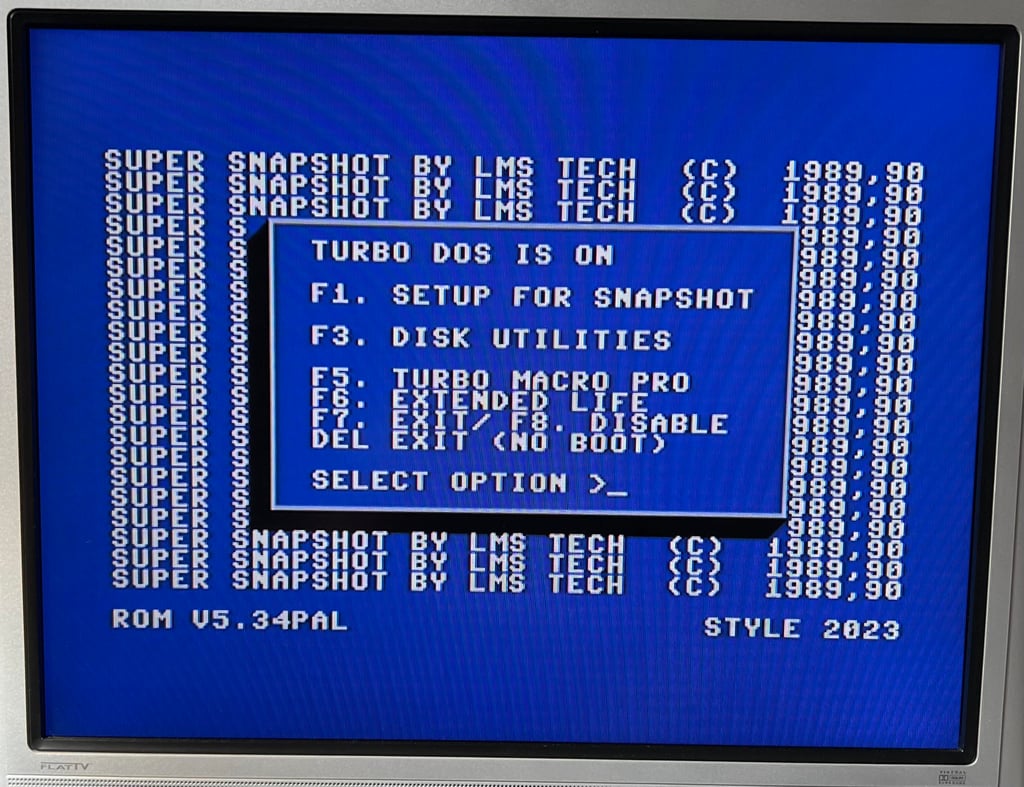
Last basic check before moving to more extensive testing is checking the cartridge. This is done by using the Super Snaphot V. Result is that the test is passed.

Extended testing
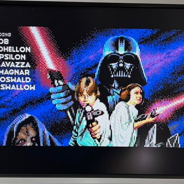
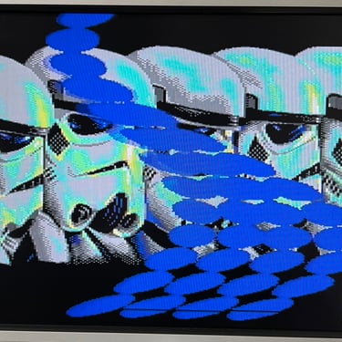
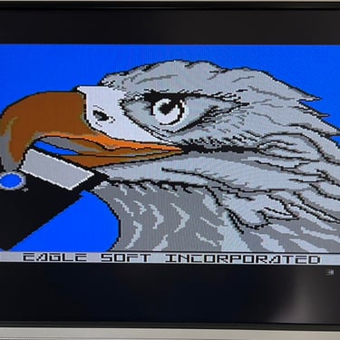
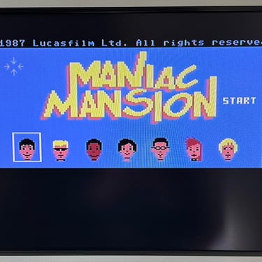
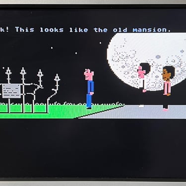
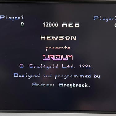
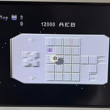
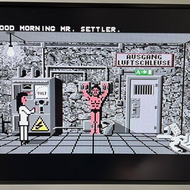
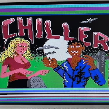
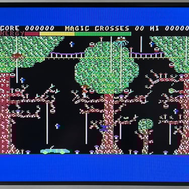
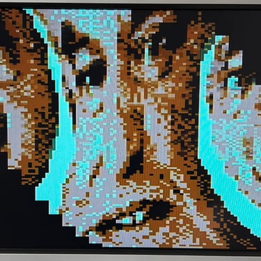
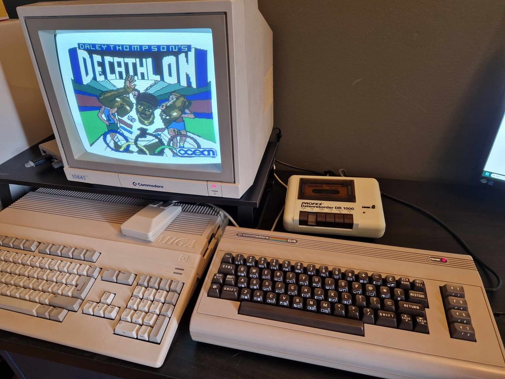
Knowing that the basic functionality of the machine works I continue the testing by using the Commodore 64 for normal operations; playing some games, watching demos, loading from datasette and floppy and using a cartridge. I can not find any issues with this machine. I also pay special attention to the video to make sure that there are no glitches in the graphics - I can´t see any abnormalities. Below is a gallery with pictures from the testing.


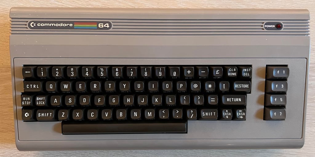
Final result
"A picture worth a thousand words"
Below is a collection of the final result from the refurbishment of this C64. Hope you like it! Click to enlarge!
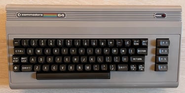


"Are you keeping up with the Commodore? 'Cause the Commodore is keepin up with you!"
Below are some pictures of the Commodore 64 back at the customer´s home!

Banner picture credits: Evan-Amos