

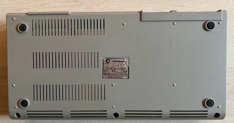
C64 Breadbin
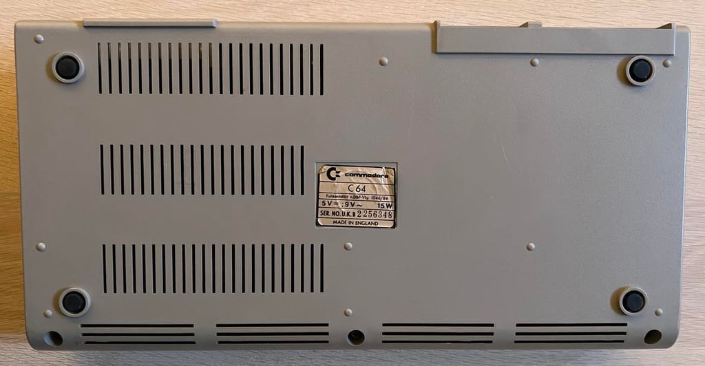
Ser. No. 2256348
Assy 250425
P/N 251470-01 (REV A)
Starting point
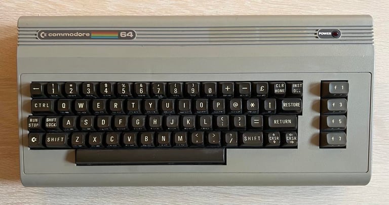
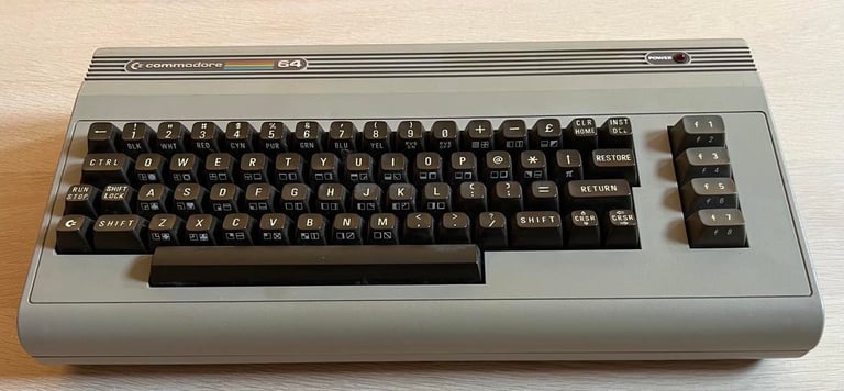
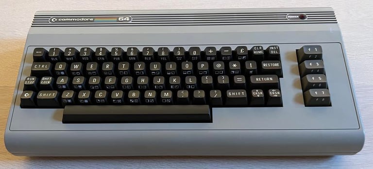
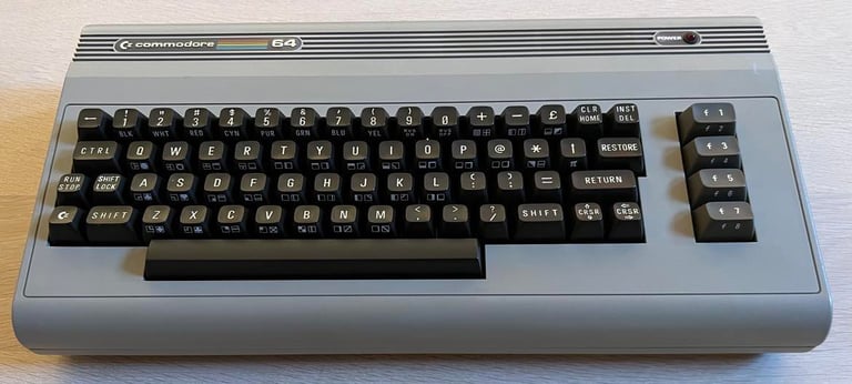
This C64 breadbin has come to me for a refurbish. The machine is known to be working so there should not be any need for repair unless I find some faults during refurbish.
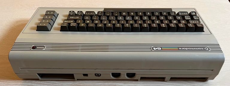
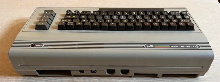
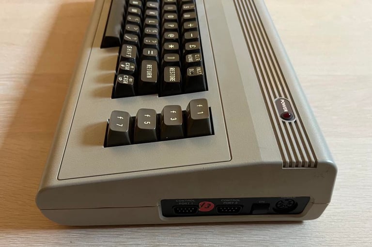
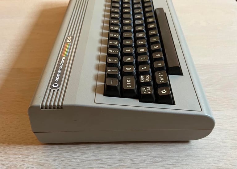
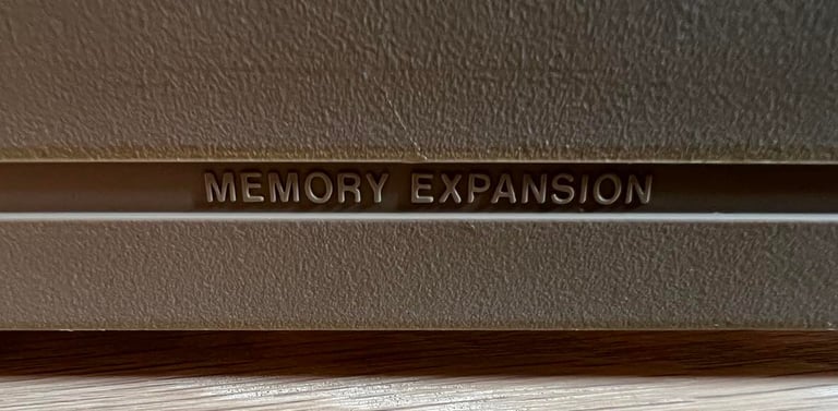
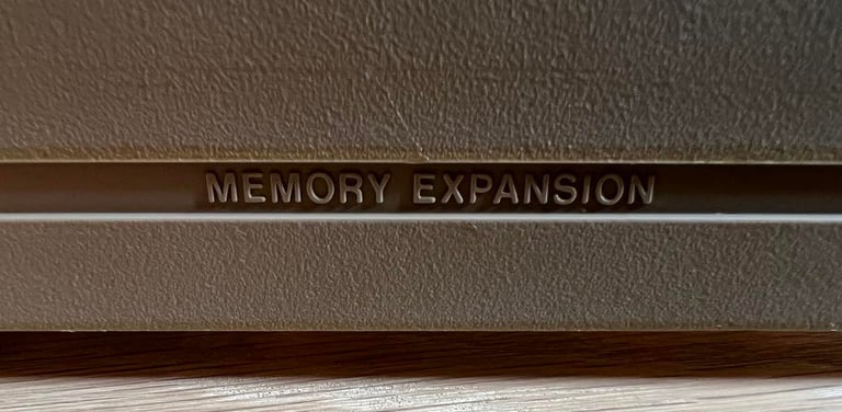
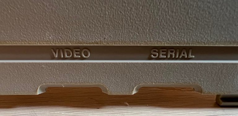
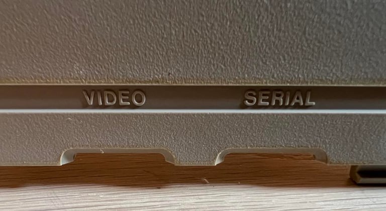
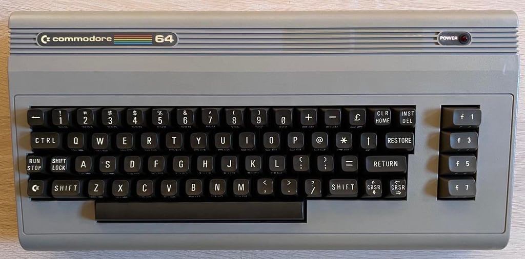
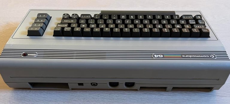
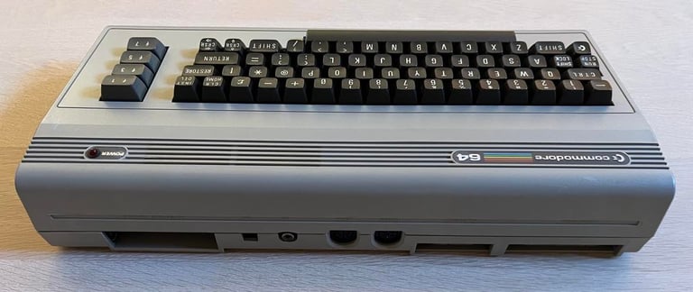
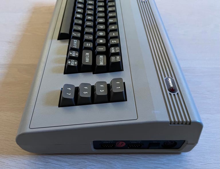
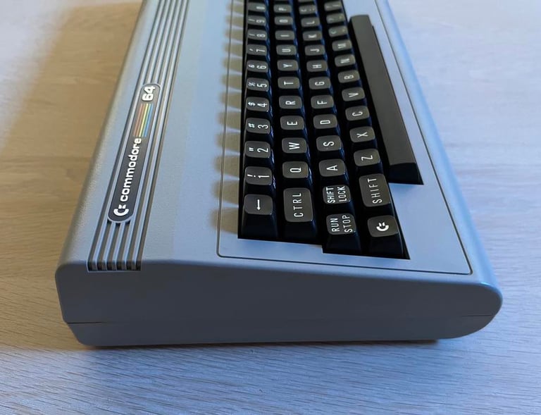
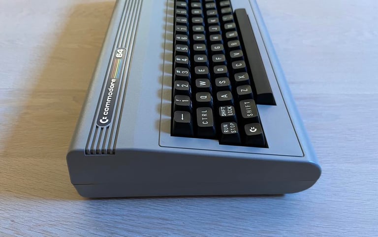
From the outside the machine looks to be in quite good condition. I can not see any severe damage to the casing. There are some small marks from cable "burns" which I will try to remove. It is not dirty, but there are some dust and grease marks which needs to be cleaned. The keyboard also looks to be in ok condition. The SHIFT-LOCK is a bit "sticky" so I will look into that. This machine also have the nice casing where the ports on the backside have text embossed .
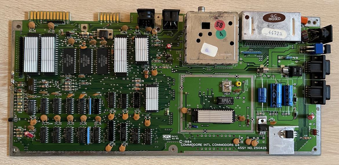
Below are some pictures before the refurbishment begins! Looking forward to this!


Refurbishment plan
The refurbishment plan for this C64 breadbin (some of them in parallell):
- Clean and remove stains from the casing
- Clean and restore the keyboard
- Refurbish main board (cleaning, checking, replacing capacitors and voltage regulators, adding heat sinks etc.)
- Recap RF-modulator
- Verify operation by testing
The plan can be updated during the refurbishment process. Sometimes I discover areas that needs special attention.
Opening it up...
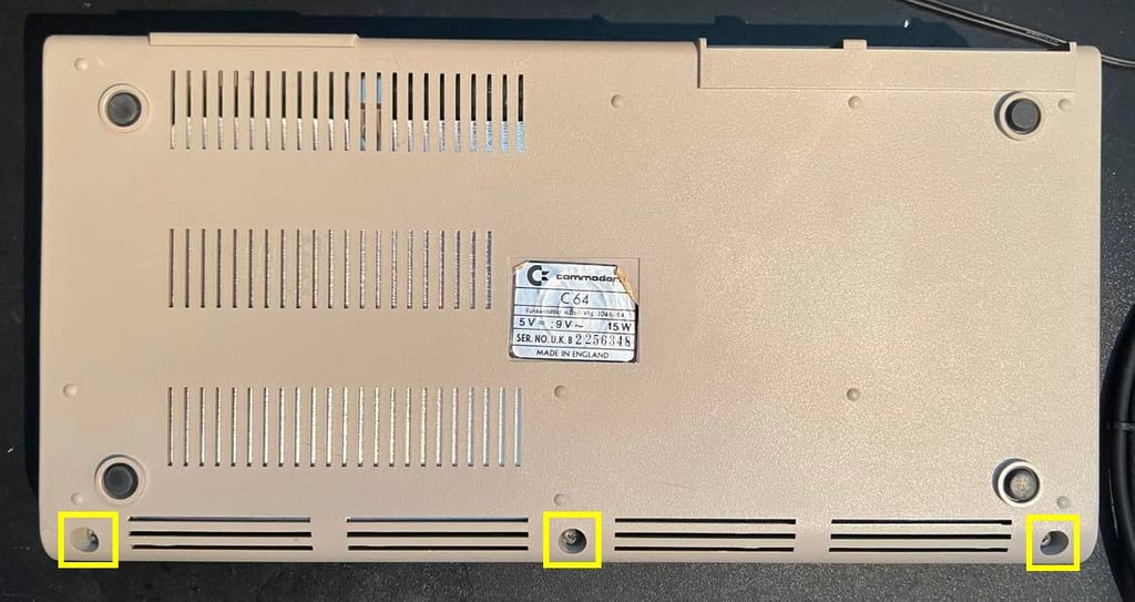
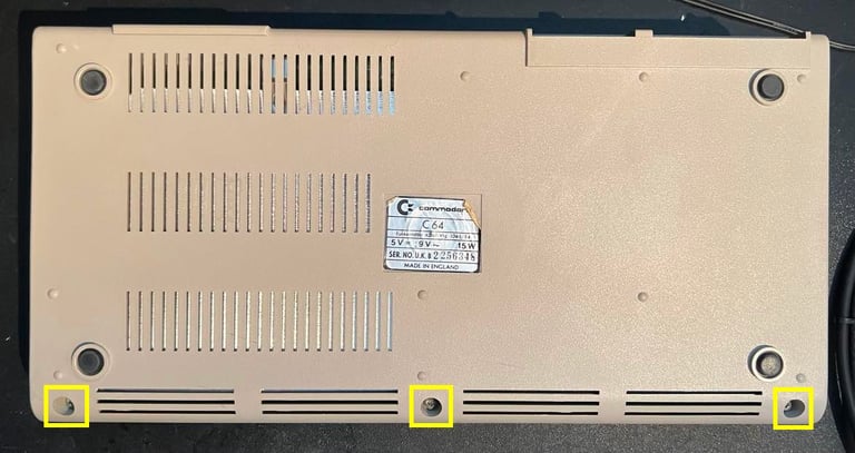
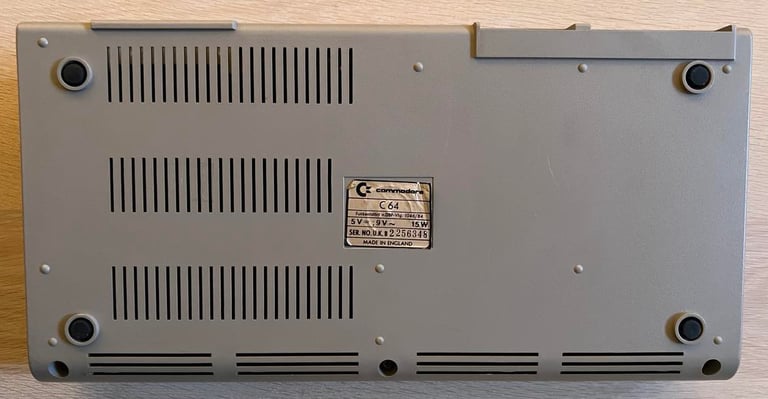
To open the Commodore 64 the three screws at the bottom are removed (picture below).
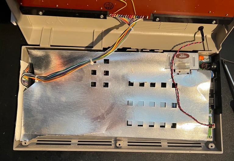
The machine is carefully opened by lifting the top cover off. To do this the top cover is lifted about 30 degrees and then gently "wiggled" until it is loose. This reveals the inside of the machine. And it looks very nice - some dust and dirt. The cardboard RF-shield is a bit torn, but that is no big deal. Also, the plastic clips on the back are intact. That is quite rare and very nice to see.

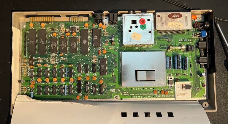
When the RF-shield is removed the mainboard PCB is revealed. Some dust and dirt, but looks in good condition. And this is the first time I see this kind of RF-shield surrounding the VIC-II area.

All the screws (7+2) are removed from the PCB. I see that two of the screws are mixed up. There should be two machine screws holding the metal bracket for the joystick ports, but one of these is a wood screw. And these wood screws should be used to hold the PCB to the bottom casing. The "wrong" machine screw is found placed in the right hand side of the PCB. This means that the PCB has probably been removed some time before.
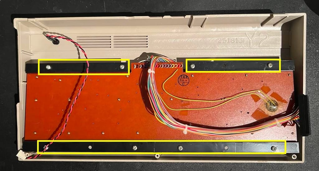
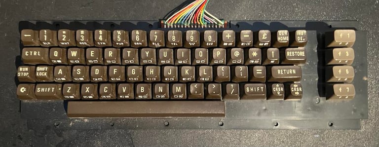
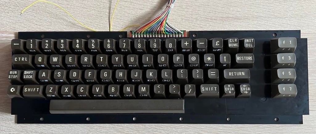
The keyboard is removed from the top cover (eight screws - yellow squares). I have never seen this kind of cable connecting the backside of the keyboard PCB. Is this a new kind?

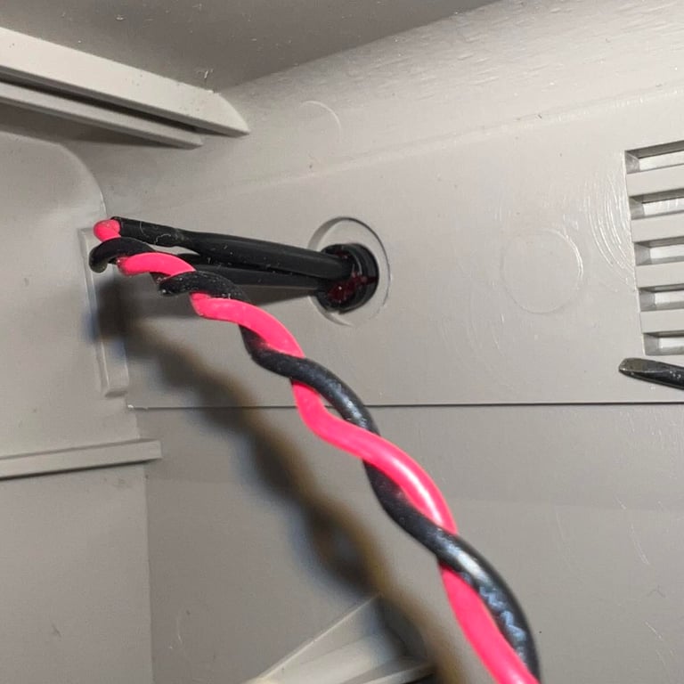
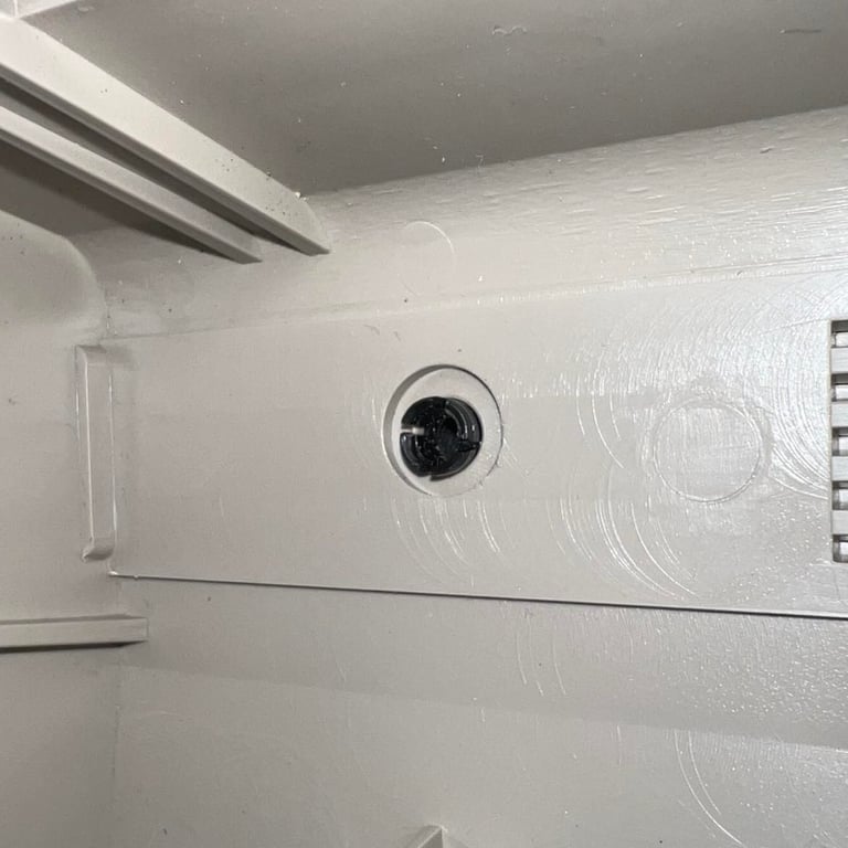
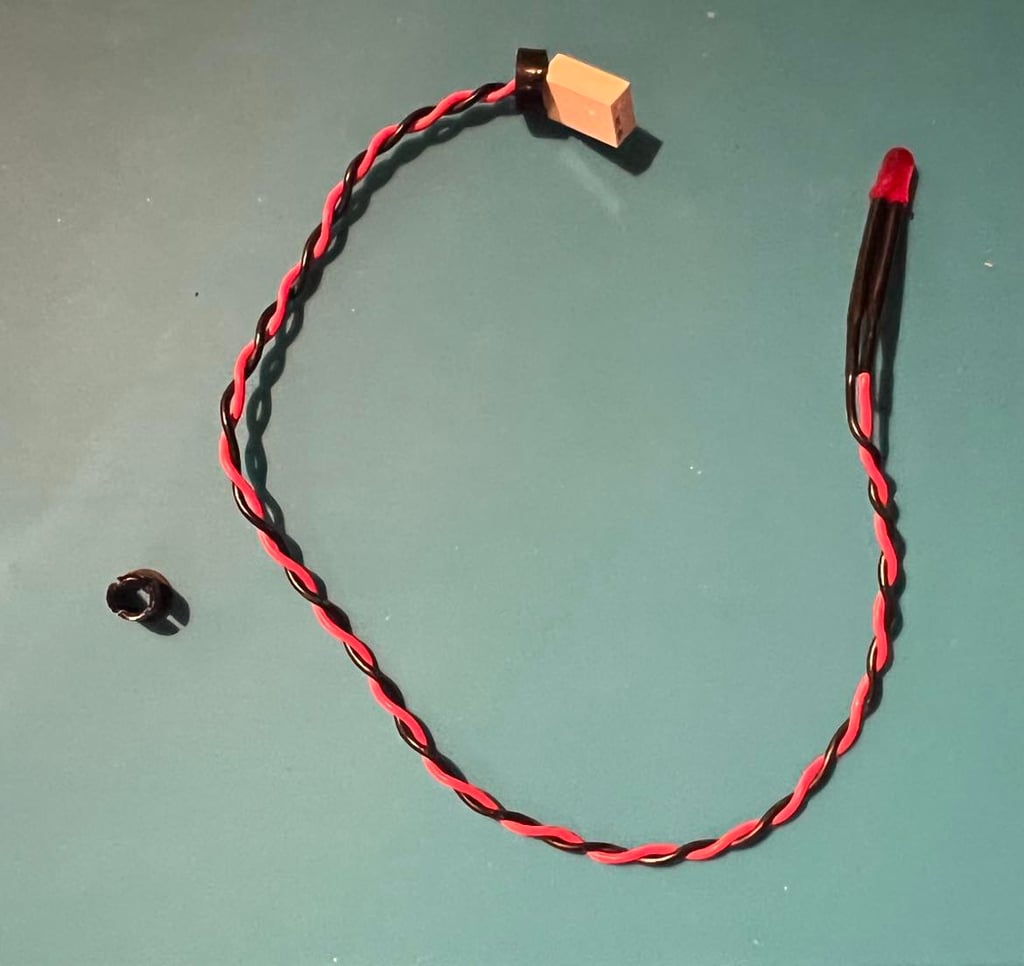
Although not strictly required it is good practice to remove the LED before cleaning the casing. This is done by carefully removing the plastic ring first, then push the LED from the front side towards the inside until it pops out and the pushing the final plastic clip from the back towards the front. Below is a small picture gallery from the process and the LED released from the casing.


Exterior casing
The top- and bottom cover are cleaned with mild soap water. This removes most of the dust and grease. But there are still some spots that needs to be removed with isopropanol.
Below is a picture of the top- and bottom cover after complete cleaning.

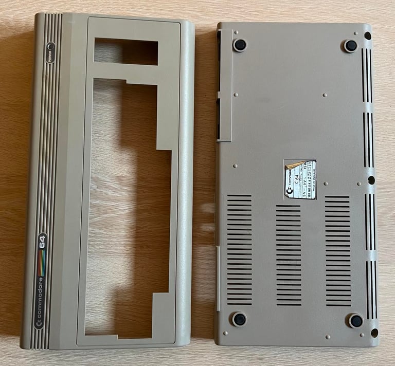
It is very nice to see that the three plastic clips are still intact. These break very easily to the brittle plastic (and can be replaced with 3D printed parts).

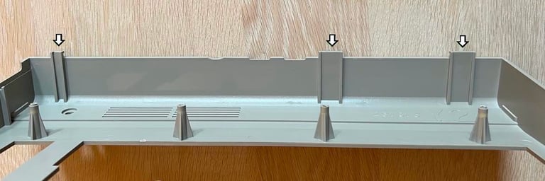
As mentioned earlier this casing also have text embossed. This is not too common on Commodore 64 breadbin cases.
Keyboard
I can tell from just touching the keys that this is not the Matsushita keyboard commonly found in the Commodore 64. And I have serviced quite a few, but I have never "felt" this kind of keyboard? It is a bit more "clicky" than most Commodore 64 keyboards. This is indeed a very unique machine!

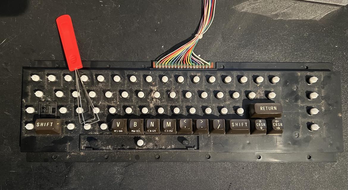
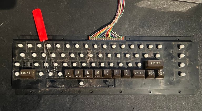
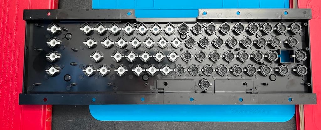
All the keys are gently removed with a key puller. There are quite some dirt and grease beneath the keys which is expected after almost 40 years. Nevertheless, is important to clean all of this away to make sure that the keyboard can continue to operate as it should.
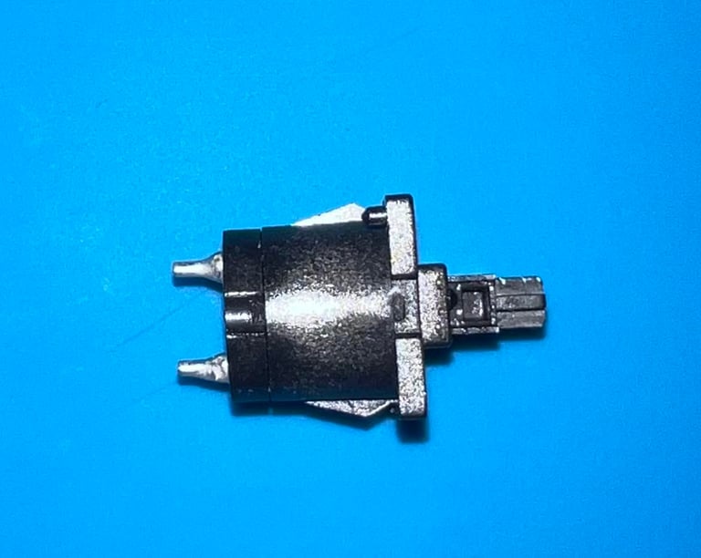
But now things get really interesting from a "Commodore 64 nerd" point of view! There are NO springs beneath the keys (?!) - the only place there is a large spring is beneath the space bar. This is indeed a special machine (at least to me). I have never seen these kind of key plungers. So very cool!
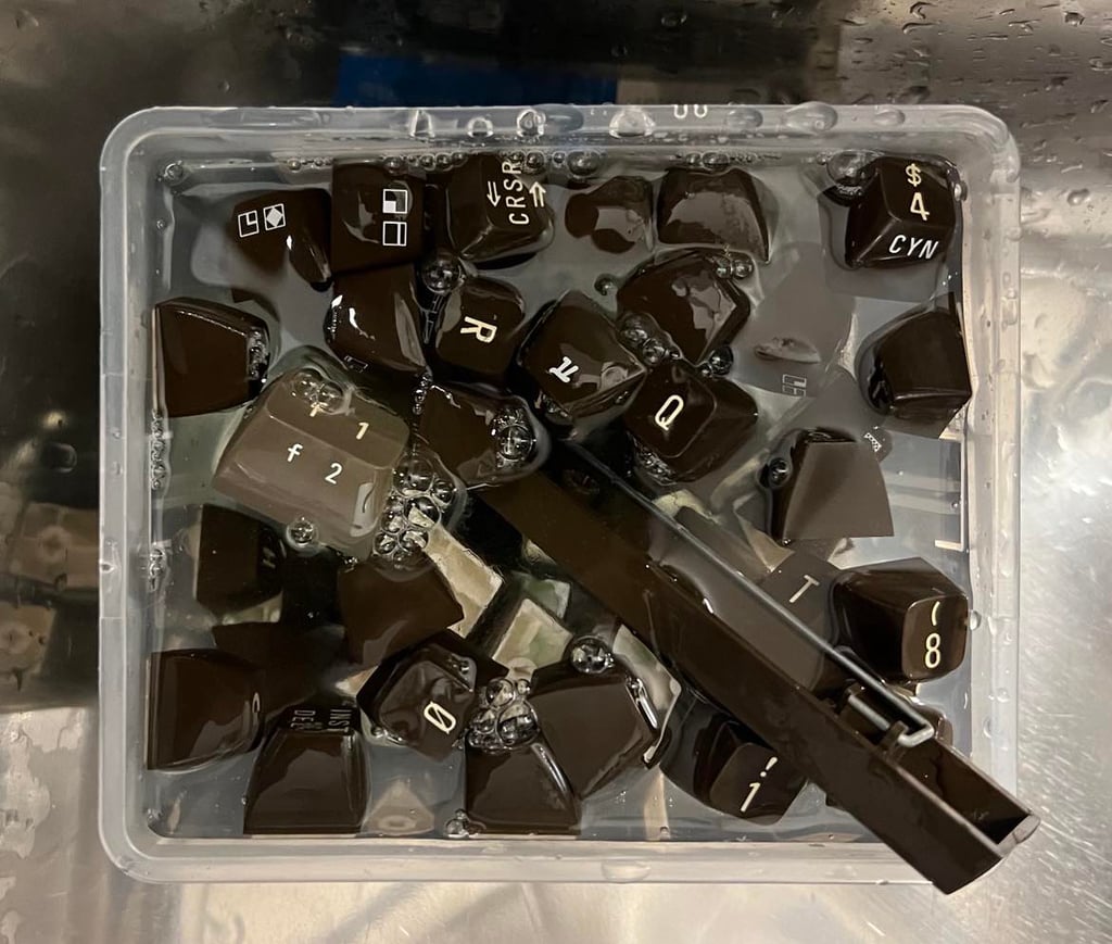
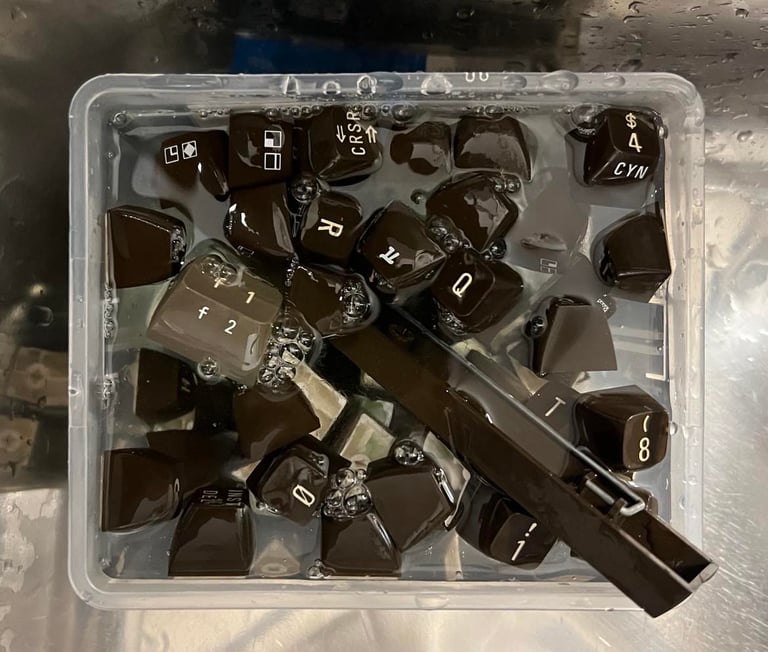
The keys are placed in a box filled with mild soap water and glass cleaning spray for a few hours. This will carefully remove all the grease from the keys.
The two wires connected to SHIFT-LOCK are desoldered. To remove the SHIFT-LOCK from the casing it is pushed from the back towards the front side. The SHIFT-LOCK is cleaned with isopropanol and contact cleaner. It is still a bit "stiff", but I think that this is the way it actually works.


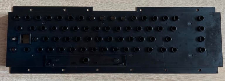
All the small screws on the back of the keyboard PCB are removed. This reveals the inside of the keyboard and now the plungers become visible.
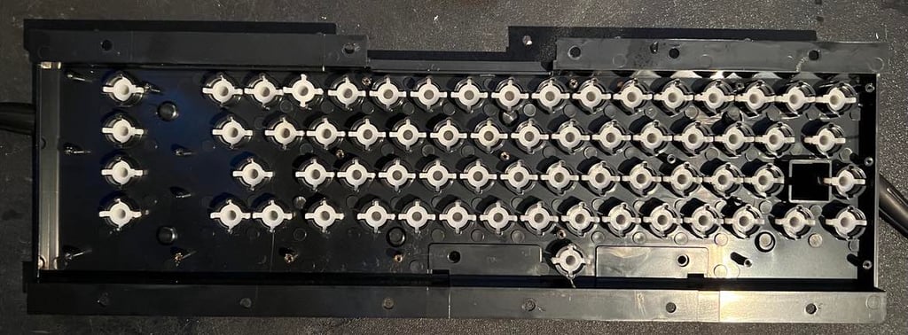
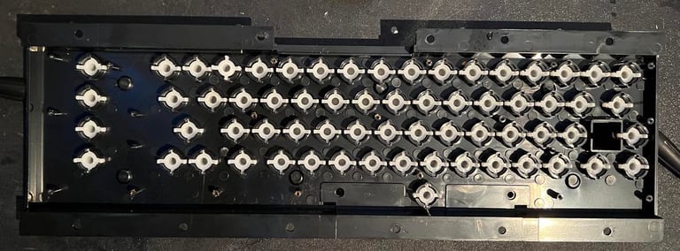
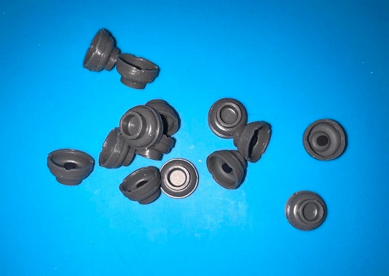
It now becomes clear to me why there are no springs (except for the space bar). Instead of springs there are for each key a rubber dome. And these rubber domes serves two purposes; both to push the key back (spring) and to create connectivity to detect a key press. Below is a picture of these rubber domes. By the way... I guess this will be a quite fiddly operation to re-assemble... well well...

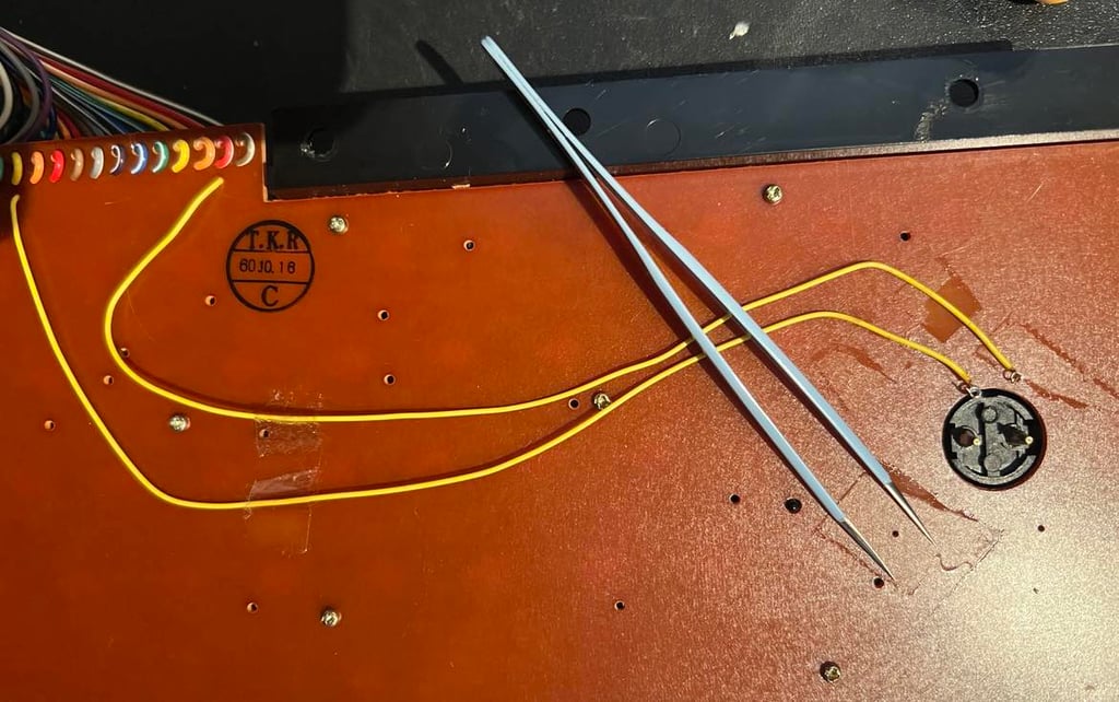
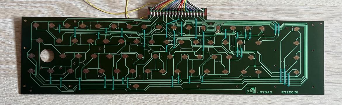
This is a J075A0 R3220101 keyboard from TKR. And as mentioned already a few times. This is the first time I have ever seen keyboard type. Very nice! The PCB is cleaned properly with isopropanol. And the PCB looks to be in very good condition. I can not see any sign of corrosion or damage.
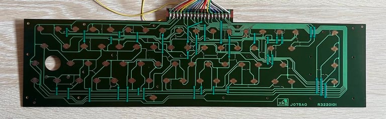
Being a real Commodore 64 nerd I had to investigate the background of this keyboard. And I see that it is not super rare, but it is rare! There are not too many of these keyboards. I think that the YouTube host Adrian Black (which is probably one of the most experienced Commodore repair person in the world) sums it up in his title for the video below: "Rare (?) Commodore breadbin keyboard curiosity". Cool!

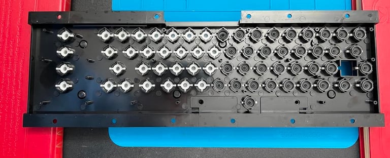
The plastic chassis / holder looks like new after cleaning. Completely spotless. It is hard to fathom that this plastic piece was made 40 years ago.

While listening to some nice music I assemble all the plungers and the rubber domes. It was easier than I feared, but it is quite time consuming. All the rubber domes are carefully placed over the plungers - one by one. Picture below shows the process - halfway!
After the keys have dried they are placed back on the keyboard. In my opinion this looks very good! I am happy with the result. You could argue that the keys are slightly yellowed. But it is not so much that I would risk retrobrighting them. Instead, I would recommend to place the keyboard in direct sunlight next summer. Sunbrighting is a way more gentle way than retrobrighting with hydroperoxide.

Mainboard
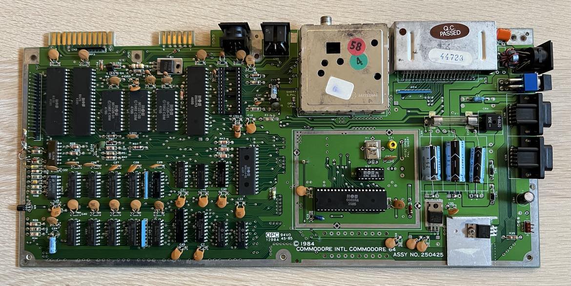
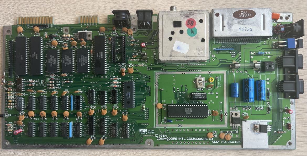
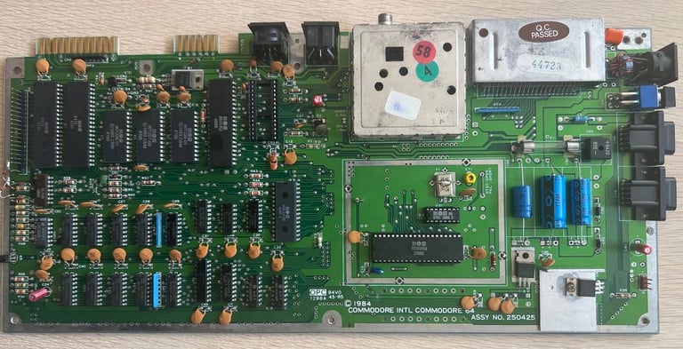
This is a assy 250425 P/N 251470-01 Rev A mainboard. As previously mentioned it looks to be in good condition. I can not see any immediate damage or corrosion to the board. It is quite dirty - the pictures does not show this very well, but this mainboard needs some proper cleaning.
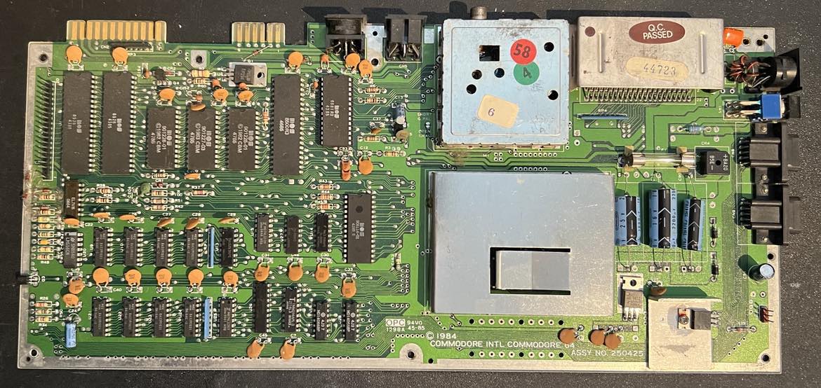
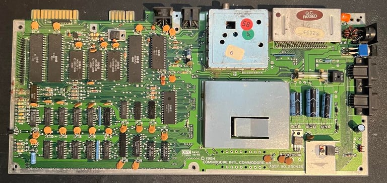
This is cool - I think this is the first time I actually see a MOS 8500 CPU in a breadbin C64! Why is this so cool? Well, most C64 breadbin use the MOS 6510 CPU. The new MOS 8500 replaced the older MOS 6510 in the Commodore 64C versions. And a little Google search confirms this "oddity":
From Wikipedia:
"In 1985, MOS produced the 8500, an HMOS version of the 6510. Other than the process modification, it is virtually identical to the NMOS version of the 6510. The 8500 was originally designed for use in the modernised C64, the C64C. However, in 1985, limited quantities of 8500s were found on older NMOS-based C64s. It finally made its official debut in 1987, appearing in a motherboard using the new 85xx HMOS chipset. "
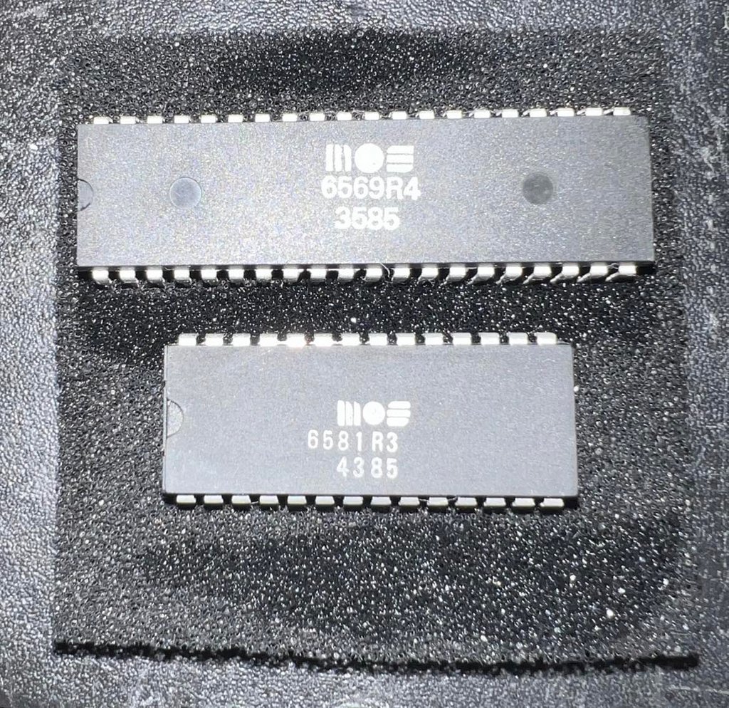
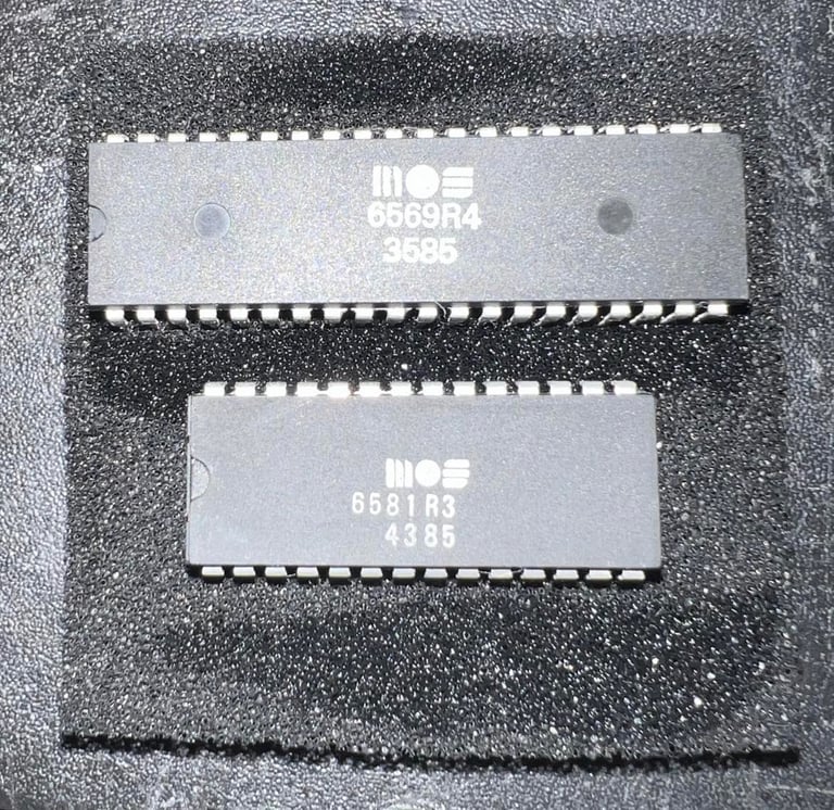
And as can be seen in the table below this machine has all of its major custom MOS chips from 1985! So this machine is part of the "limited quantities in 1985" reference above! Cool!
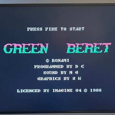
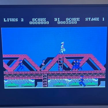
I think it is likely that this machine was produced late 1985. Most of the MOS custom chips were manufactured between week 35-47 in 1985. Maybe some lucky child got this magnificent machine for Christmas in 1985? Playing Green Beret and listening to "Take on me (A-ha)".
Removing the VIC-II RF-shield
The RF-shield surrounding the VIC-II is removed. This shield does no longer have any real function since the Commodore 64 will not interfere (electromagnetic) with nearby devices (and vice versa). This was a thing back in the 1980s where electronic devices had to comply with FCC regulations for electromagnetic emissions. The only thing the RF-shield does now is to encapsulate heat around the VIC-II. And this is not good for the lifespan of the chip. The VIC-II is already a very hot chip and it is therefor wise to remove anything preventing heat from escaping.
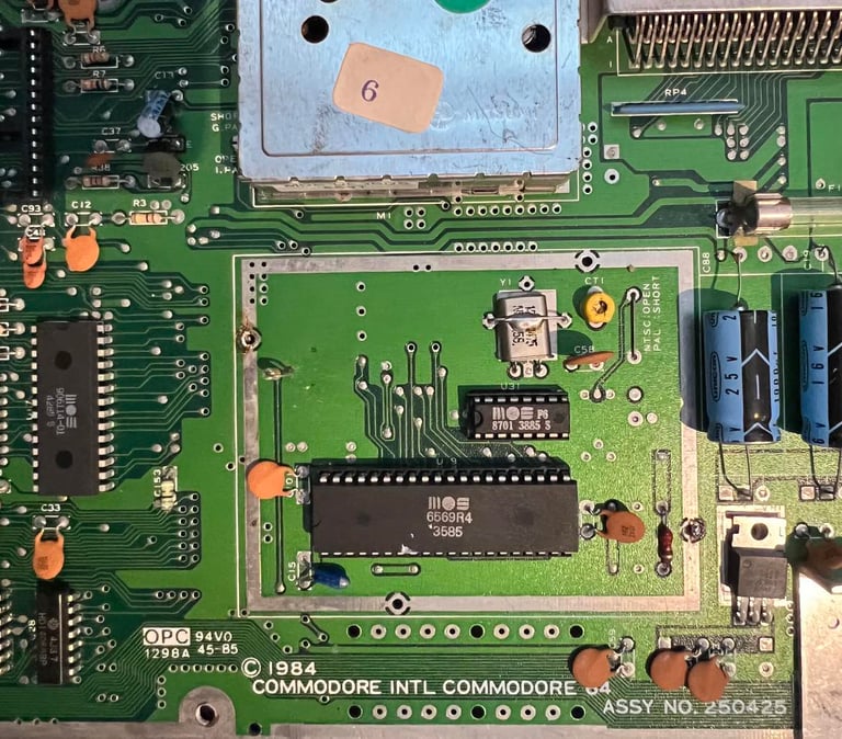
To remove the RF-shield the two metal tabs on the side of the casing are desoldered while using a chip lifter prying it off. There are no traces connected to the casing (other than the ground plane), but no traces or pads are damaged during desoldering. Below is a picture of the VIC-II area with the RF-shield removed. Note that the clock circuit is only the single MOS 8701 chip instead of using multiple ICs to generate the clock. The MOS 8701 is also socketed which is a good thing - if this chip should fail some day there are modern replacements that can be bought.

Cleaning the mainboard
It is good practice to clean the mainboard PCB properly before continuing with re-cap etc. This is to get rid of all dirt and grease - but it also helps to check that there are no damage or corrosion. It is easier to see these things when the board is clean. Before the mainboard is cleaned with mild soap water and a soft paint brush the SID- and the VIC-II chip is removed. Not because they are not waterproof (they are), but it is much faster and easier to dry the sockets when the chip is out of the way. The fuse is also removed (this is not actually waterproof!)
To remove ICs from sockets it is smart to use a professional chip lifter. Carefully prying the chip from each side in turn releases the ICs without damaging the socket or the chip itself. All the pins of the SID- and VIC-II chips are cleaned with a glass fibre pen and isopropanol, and then placed an anti-static pad.
Note that the water is very clean in Norway so it is no problem to use that instead of ultra clean water (such as battery water). But what is always a good thing is to soak the board in isopropanol to speed up the evaporation. The mainboard is left to dry for about 12 hours.
The mainboard looks very nice after cleaning. I know it is "nerdy" but I really enjoy working on a super-clean Commodore 64 mainboard. And I am amazed again and again how "new" this looks and at the same time knowing that this mainboard was manufactured when I was 10 years old...

Visual inspection
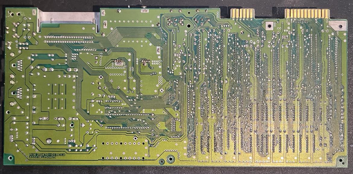
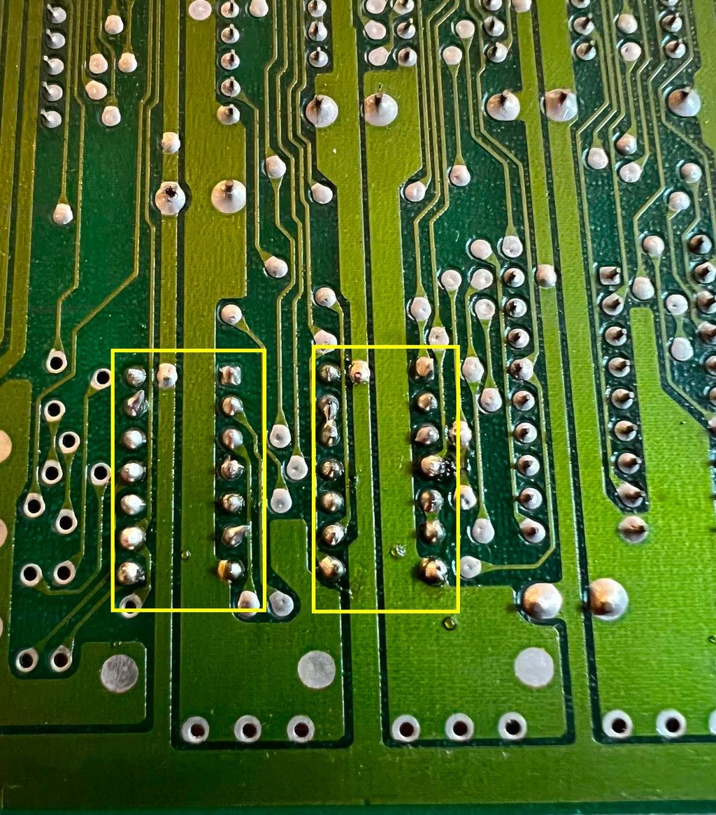
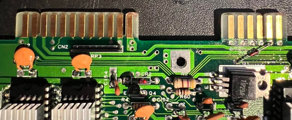
After cleaning the mainboard I do a close visual inspection. I can not see any damage or corrosion to the board. But I now see that this Commodore 64 has probably been repaired at some time. Beneath the two CMOS 4066 ICs (bilateral switches) I see clear signs of soldering re-work. So probably one (or both) of these were faulty some time and replaced. The machine is working, but I am not very pleased with the way the soldering is done. In the picture below is hard to see, but some of the soldering points doesn´t seem to be properly soldered (cold soldering)? So I will resolder these points later.

Checking the voltages
It is good practice to check the C64 voltages. Why? A good working machine will show voltages within acceptable tolerances - so to measure this you will easily detect if "something is rotten in the state of Denmark". As the table below (which will be updated after the electrolytic capacitors are replaced) all voltages are within acceptable tolerances.
Replacing the electrolytic capacitors
Electrolytic capacitors dry out (or sometime start leaking) due to old age. Even if this is not the biggest cause of failure on the Commodore 64 a mainboard with old capacitors can produce odd behaviour. So it is good practice these with new modern types. A list of the capacitors which are replaced can be found in this list of capacitors (check assy 250425).
Note that the 470 uF capacitor is replaced with a slightly higer voltage rating. Instead of using 25 V a 35 V capacitor is used. This is not any issue since the voltage rating is higher than required.
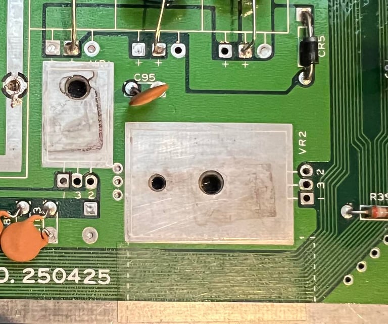
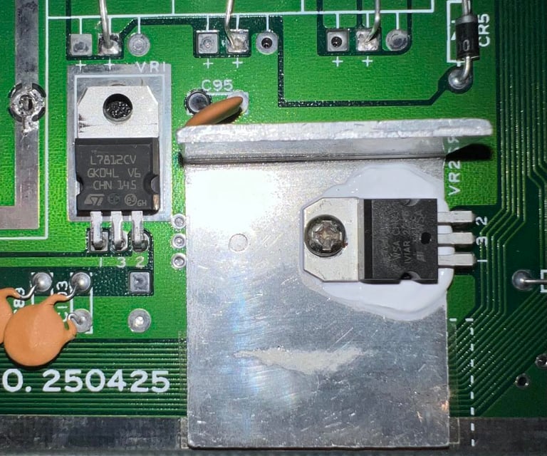
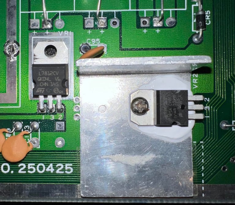
Replacing the 5 V- and 12 V voltage regulators
In addition to the 5 VDC and 9 VAC coming from the powersupply (PSU) a 5 VDC and 12 VDC are generated inside the Commodore 64. These two additional voltages are sourced from a 7805- and a 7812 voltage regulator. See the article about voltages within the Commodore 64 for further details.
Both voltage regulators are desoldered and no pads/traces were lifted. New regulators are soldered back in. Note that it is only the 7805 (5 V) regulator which is mounted on a heat sink. This is normal. Also, a small drop of heat paste is placed between the voltage regulator and the heat sink. See pictures below.

Cleaning the user- and datasette port
Both the user- and datasette port are cleaned with first with a rubber eraser and then isopropanol. It is crucial that these contacts are clean to make sure they operate as they should (e.g. loading a game from cassette).

Adding heat sinks
Some of the major ICs of the Commodore 64 can get quite hot and heat could catalyst the deterioration of a chip. Therefore heat sinks are placed on some of the most important ICs; SID, VIC-II, 2xCIA, CPU and PLA. Even though most of the heat still is still transferred trough the IC pins soldered to the board the heat sinks will assist in the heat transfer from the IC package to the surround air.
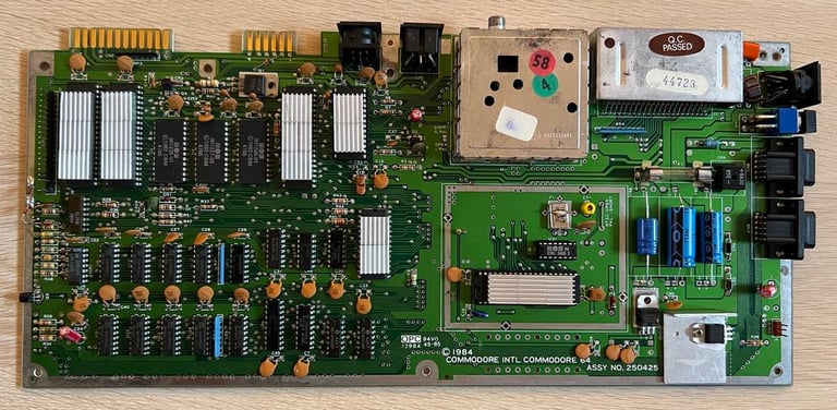
In the pictures below the now completely refurbished mainboard is shown - both before and after heat sinks are added. All voltages are measures again and the voltage table in the beginning of this chapter is updated.
Replacing the electrolytic capacitors - RF modulator
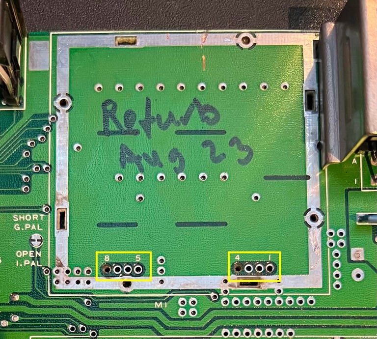
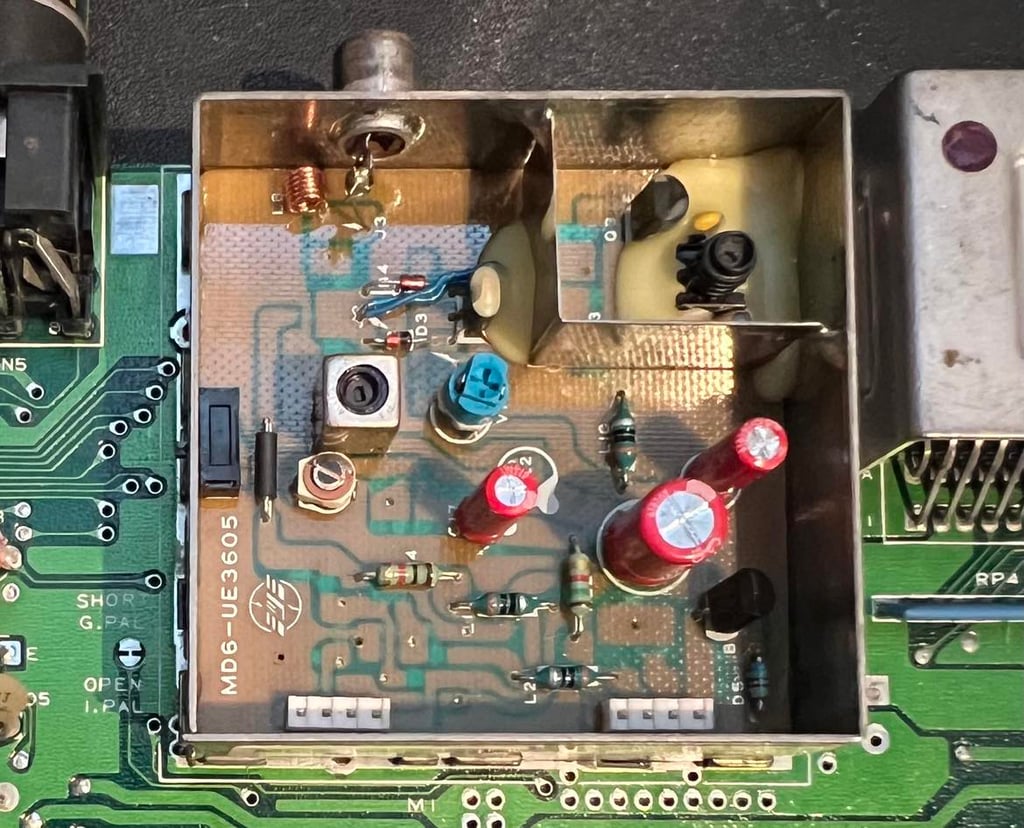
This is a RF-modulator from Mitsumi (MD6-UE3605) containing three electrolytic capacitors. But to replace the capacitors the RF-modulator first needs to be desoldered which is not a trivial operation. Use a combination of desoldering gun, soldering iron and hot air to remove the module from the mainboard - see HOWTO desolder the RF-modulator article.
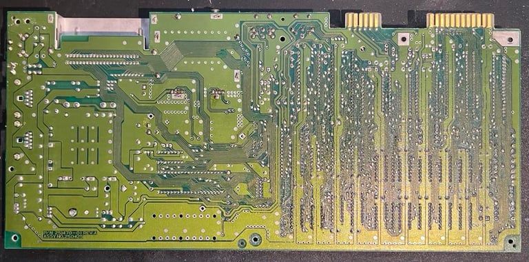
In the picture below the mainboard is shown with the RF-modulator. Note that two pads were actually lifted during desoldering (pin 8 and 4) on the top side of the mainboard. But this has no impact at all since these two pads are not connected to anything on the top side. Only on the bottom these are connected.

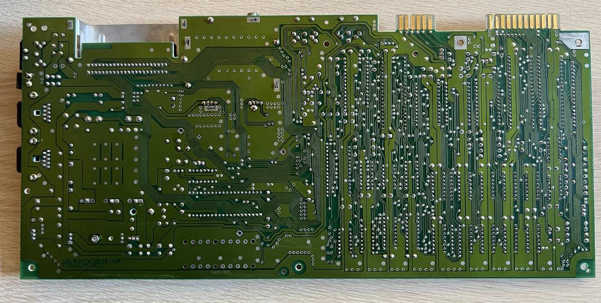
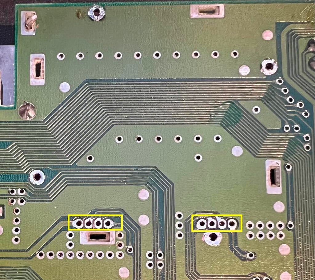
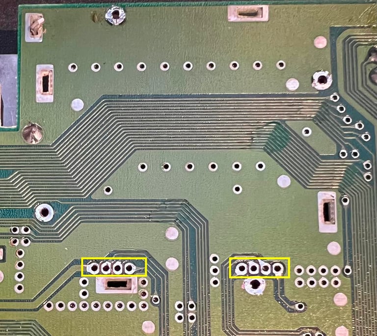
On the backside no traces or pads are lifted after desoldering.
The electrolytic capacitors are replaced - nice shiny red capacitors from Wurth Electronics. And the RF-modulator is soldered back on the mainboard.

Testing
Proof is in the pudding - does it work?
Testing is done through two main stages:
Testing the basic functionality and chips
Testing by using the machine playing demos, games etc. accessed by both floppy and datasette to verify correct operation
Basic functionality and chips
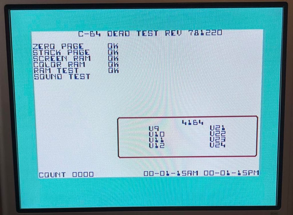
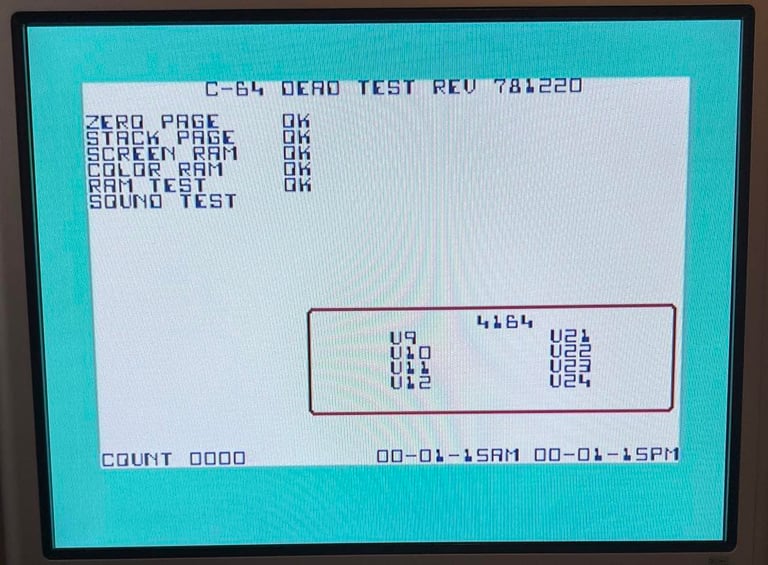
First test is done using the Dead Test Cartridge. This test doesn´t test all the functionality of the Commodore 64, but it does test the basic functionality of the major chips such as the CIA #1/2, CPU, VIC-II, PLA, RAM and SID. As the picture shows below the test is passed.
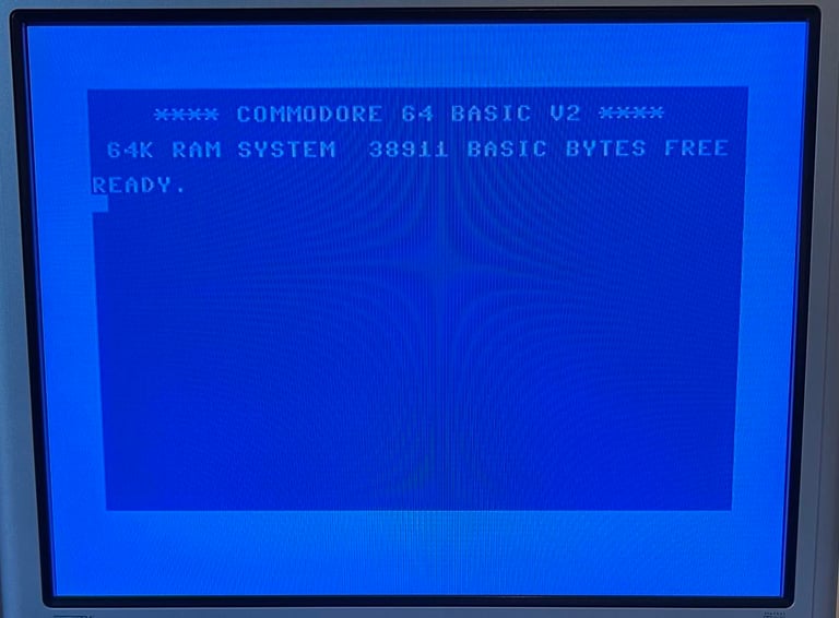
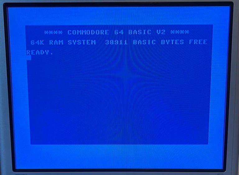
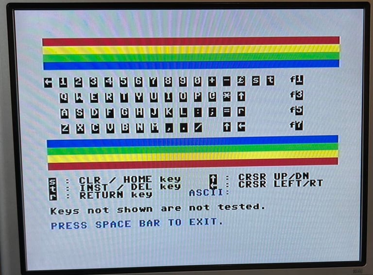
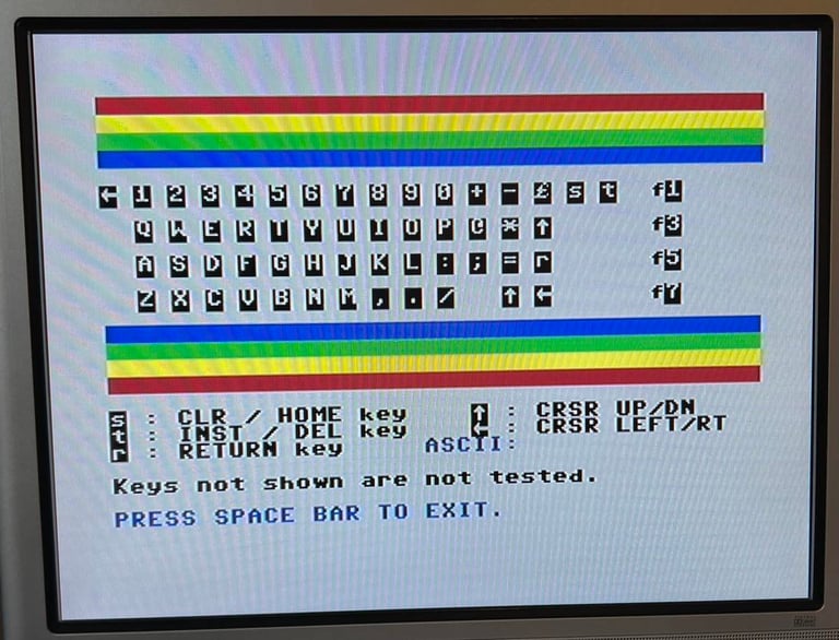
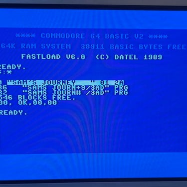
Next test is to power the Commodore 64 to the blue boot up screen and also check the keyboard to make sure all keys works as they should. The test is passed; all keys works and 38911 BASIC Bytes Free.
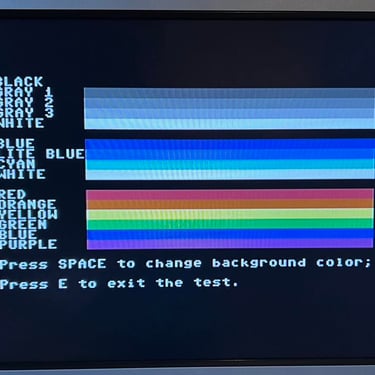
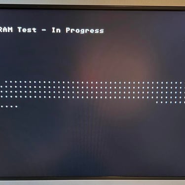
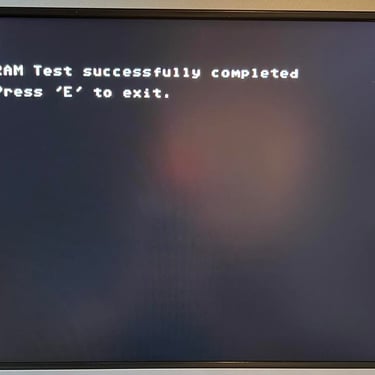
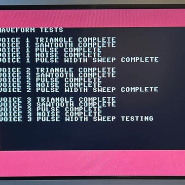
The basic functions of the VIC-II, SID and RAM is tested with 64 Doctor. Note that this is to be considered as basic functionality - more advanced (?) functionality such as sprite handling / collision detection / advanced audio will be tested later. But the basic tests pass without any detected faults (click to enlarge).
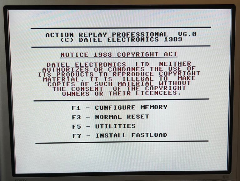
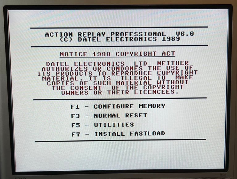
Last basic check before moving to more extensive testing is checking the cartridge. This is done by using the Action Replay VI. Result is that the test is passed.
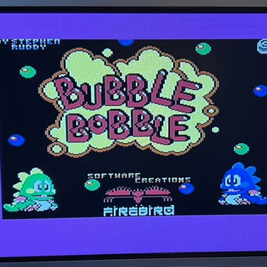
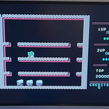
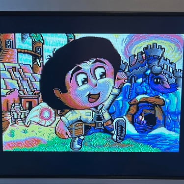
Extended testing
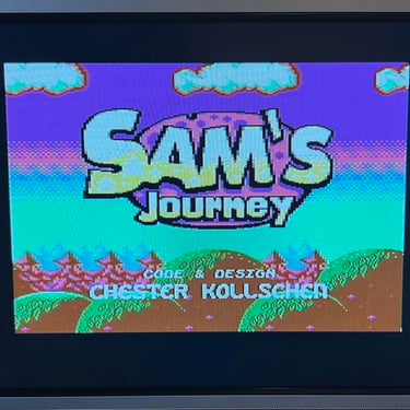
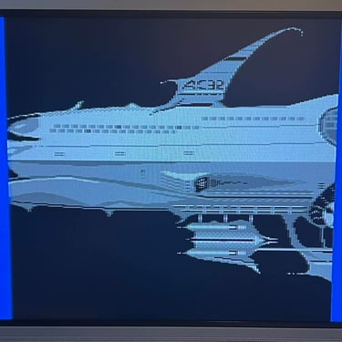
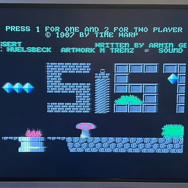
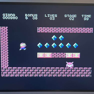
Knowing that the basic functionality of the machine works I continue the testing by using the Commodore 64 for normal operations; playing some games, watching demos, loading from datasette and floppy and using a cartridge. I can not find any issues with this machine. I also pay special attention to the video to make sure that there are no glitches in the graphics - I can´t see any abnormalities. Below is a gallery with pictures from the testing.


Final result
"A picture worth a thousand words"
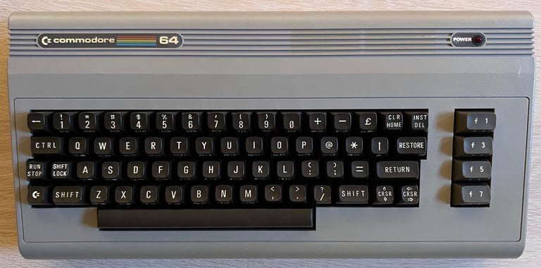
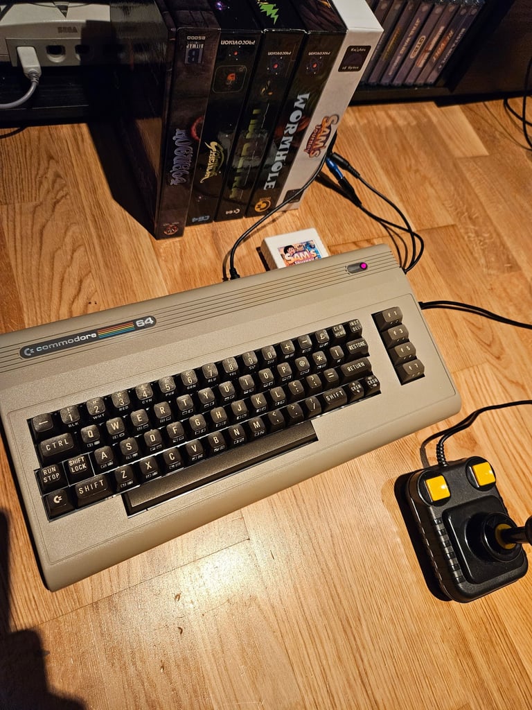
Below is a collection of the final result from the refurbishment of this C64. Hope you like it! Click to enlarge!
"Are you keeping up with the Commodore? 'Cause the Commodore is keepin up with you!"
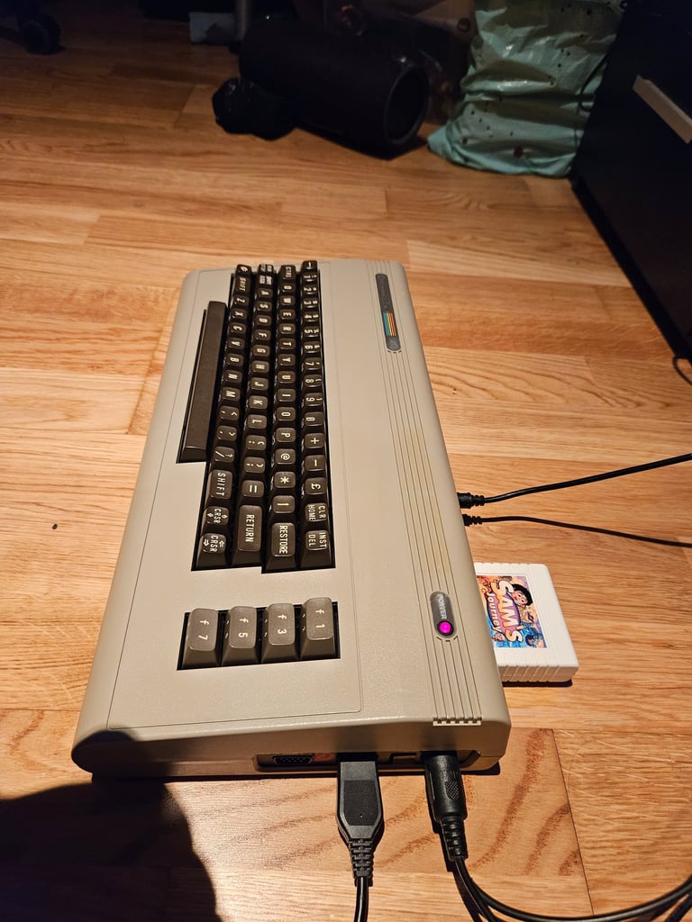
Below are some pictures of the Commodore 64 back at the customer´s home!
Banner picture credits: Evan-Amos