

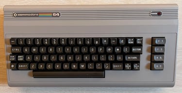
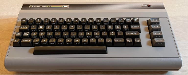
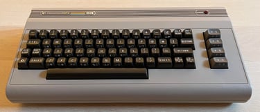
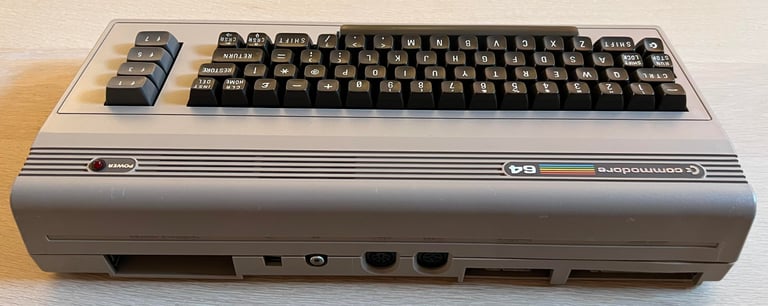
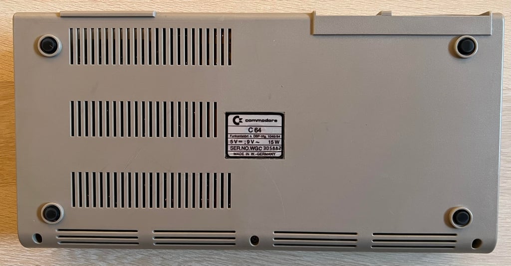
C64 Breadbin [PAL]
Ser. No. 305882
Assy 250425
P/N 251470-01 (REV B)
Starting point
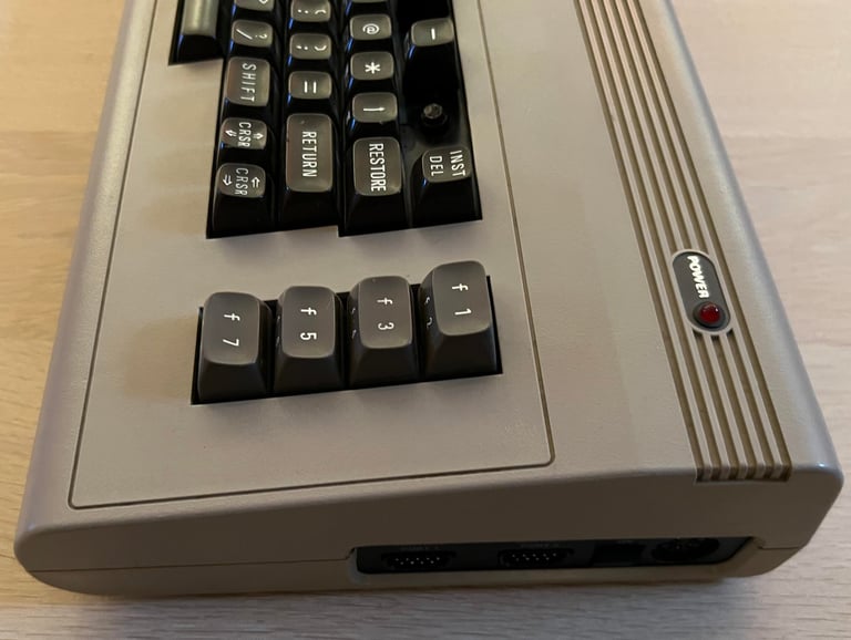
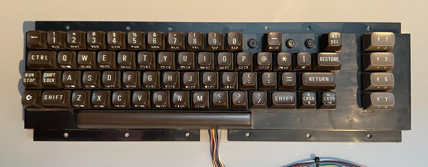
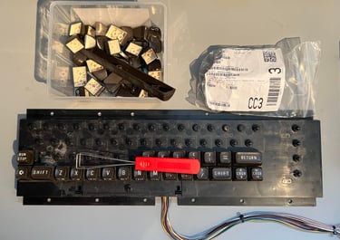
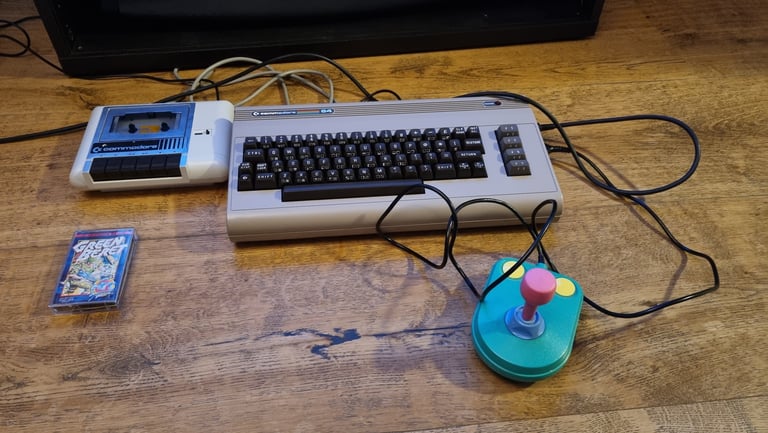
This machine was sent for some refurbishment including a repair. Apparently the joystick port #2 is not working as expected as some of the directions (UP/DOWN/RIGHT/LEFT) are not registered while using a joystick in this port. In addition some of the keycaps "+", "£" and "CLR HOME" are missing.
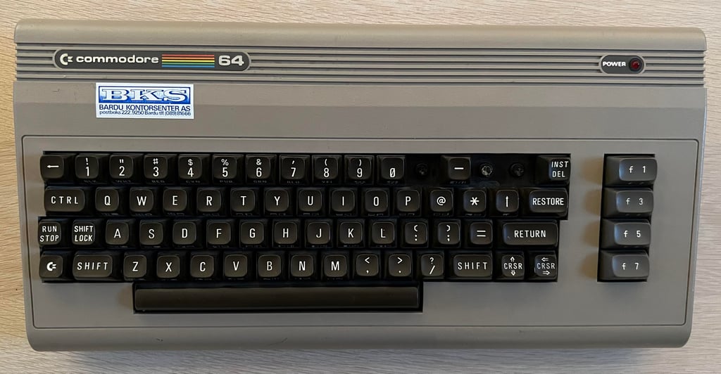
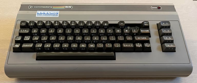
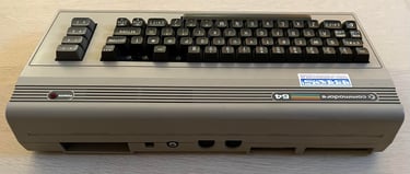
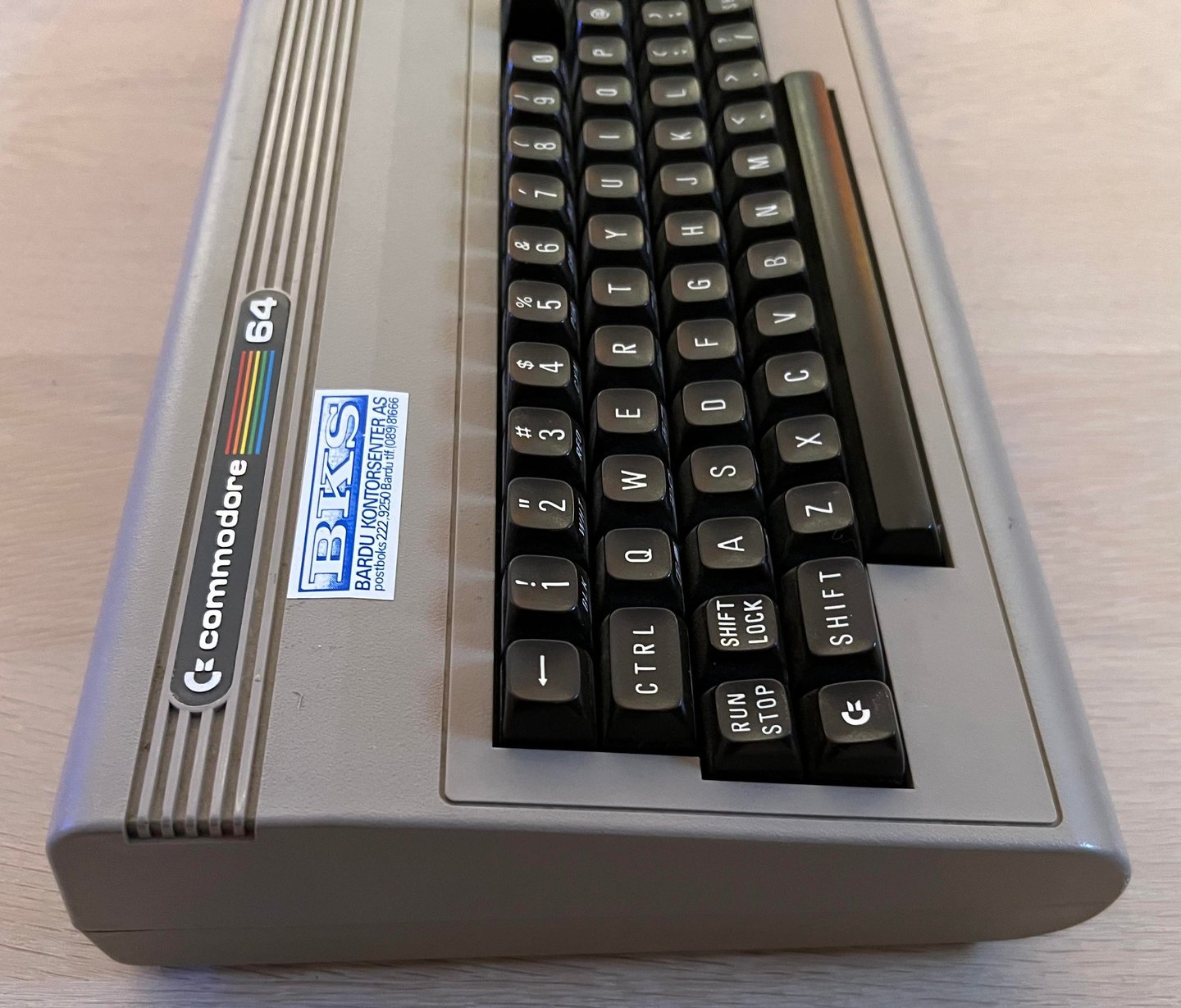
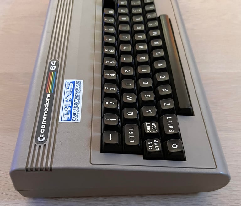
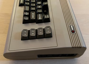
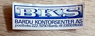
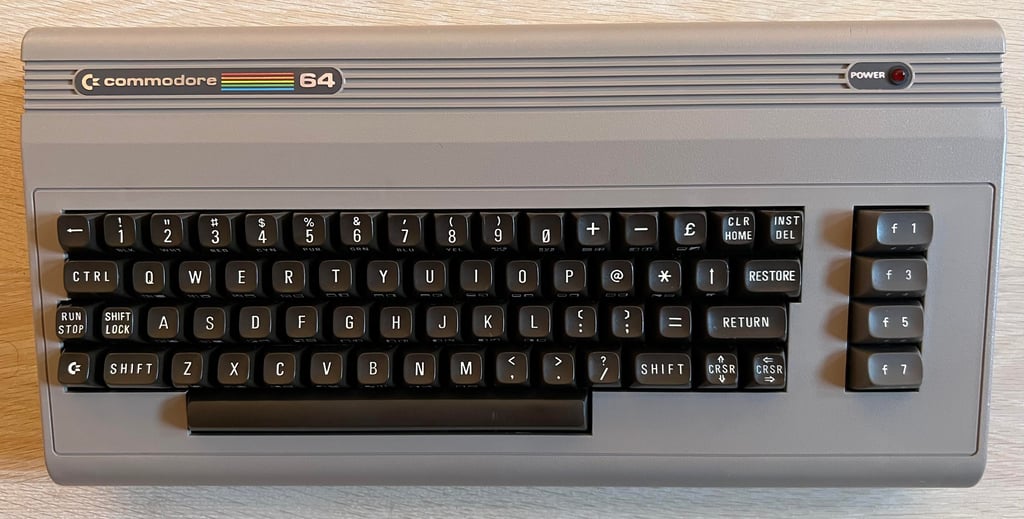
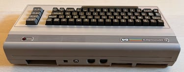
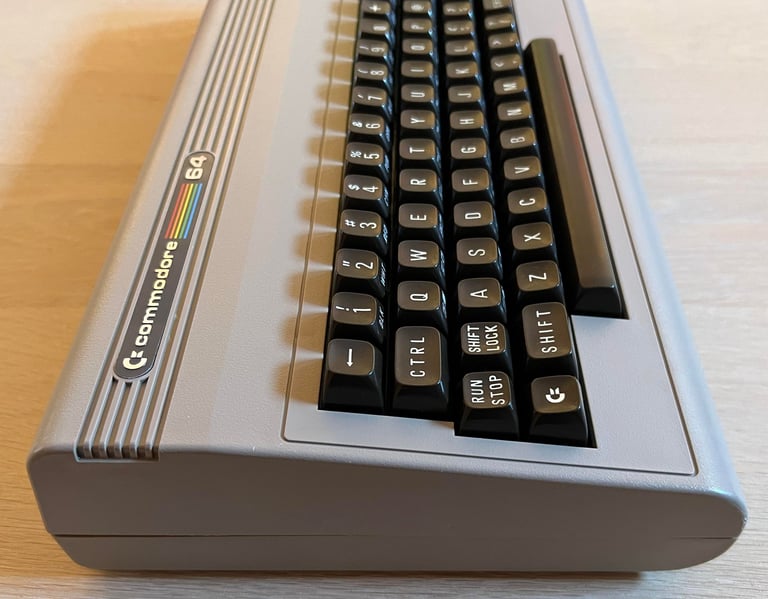
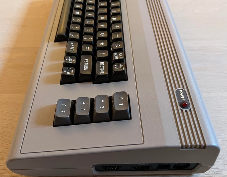
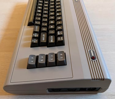
From the outside the machine looks to be in fine condition (neglecting the missing keycaps). There are some sign of use such as small rifts in the "RETURN" and "CRSR UP/DOWN" key and small scratches - but this is marginal. On the top cover there is a sticker saying "BKS - Bardu Kontorsenter AS" which is from the store where the machine was purchased back in the 80s in Norway. That is very cool!
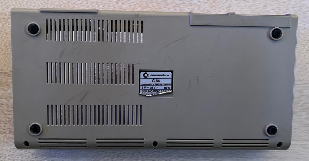
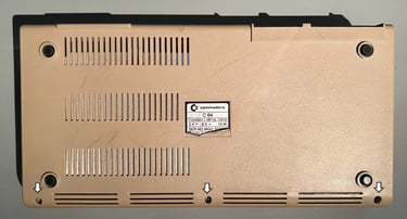
The machine is not very yellowed, but I think it some retrobright should bring it back even closer to its original colour. All the remaining keys feels intact and I can not see any damage to the machine anywhere. The sticker on the bottom cover is partly loose, but this is normal.
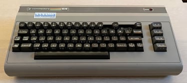
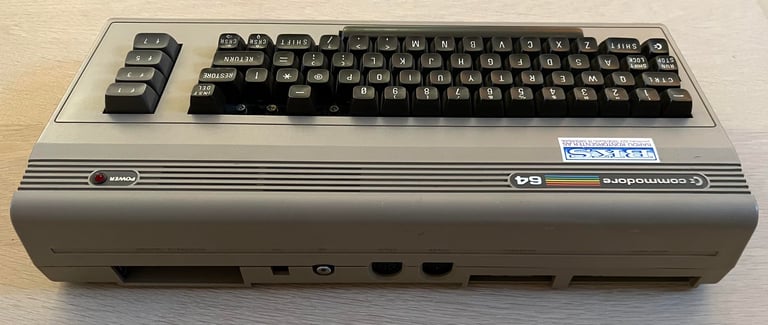
Below are some pictures before refurbishment.

Refurbishment plan
The refurbishment plan for this C64 breadbin (several of them in parallell):
- Refurbish the casing (cleaning, repairing and retrobrighting)
- Refurbish the keyboard (cleaning and reviving the plungers)
- Refurbish main board (cleaning, checking, repairing, replacing capacitors and voltage regulators, adding heat sinks etc.)
- Recap RF-modulator
- Verify operation by testing
The plan can be updated during the refurbishment process. Sometimes I discover areas that needs special attention.
Opens it up...
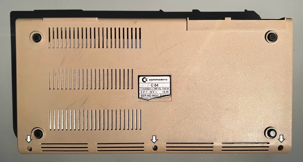
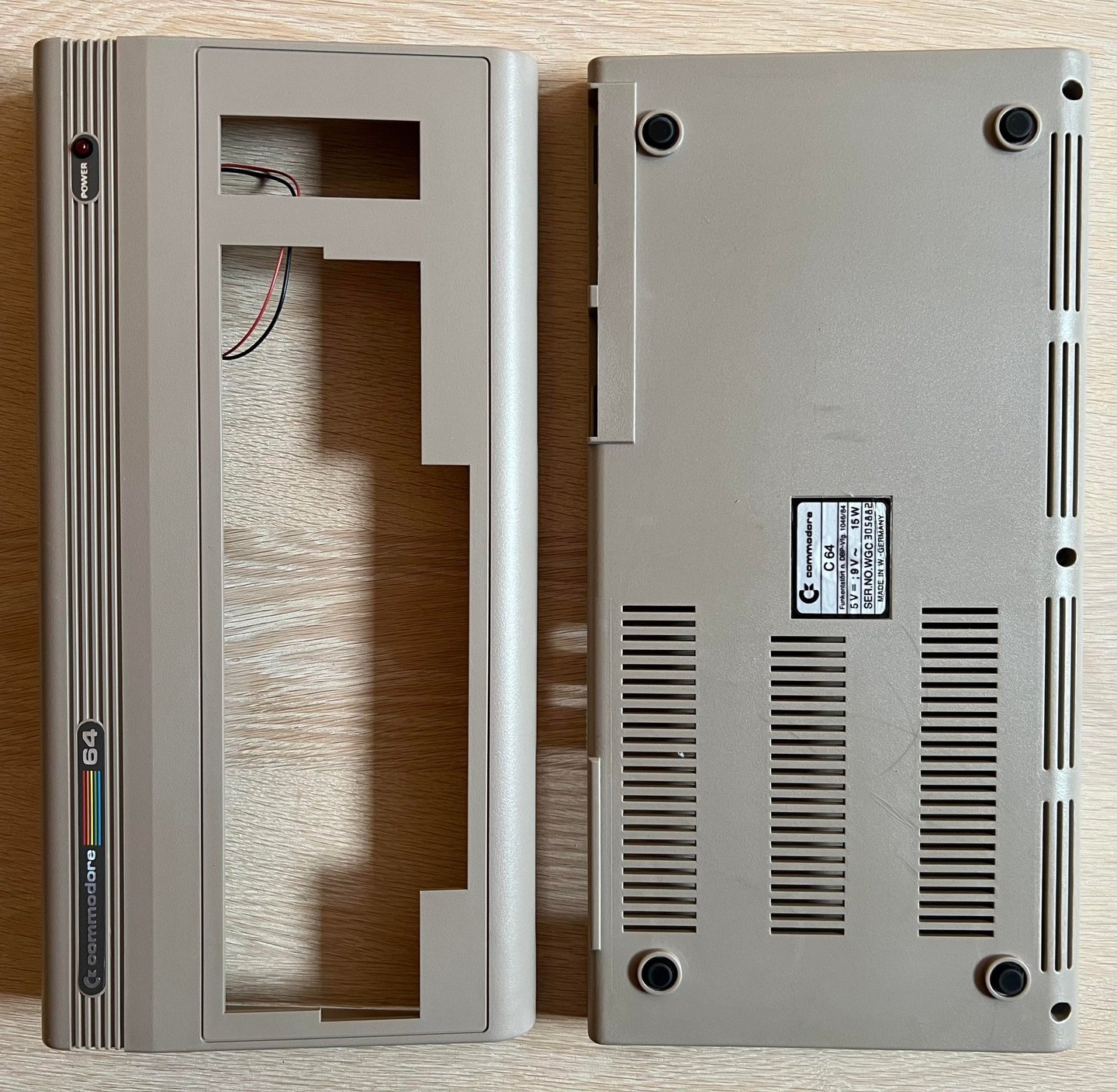
To open the Commodore 64 breadbin the three screws at the bottom cover are removed first.
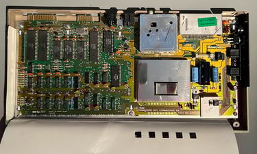
With the screws out of the way the top cover is lifted about 30 degrees before carefully wiggled to release it from the bottom cover. This reveals the inside of the machine - and it looks very (!) nice. Almost no dust, and the cardboard RF-shield appear to be in perfect condition.
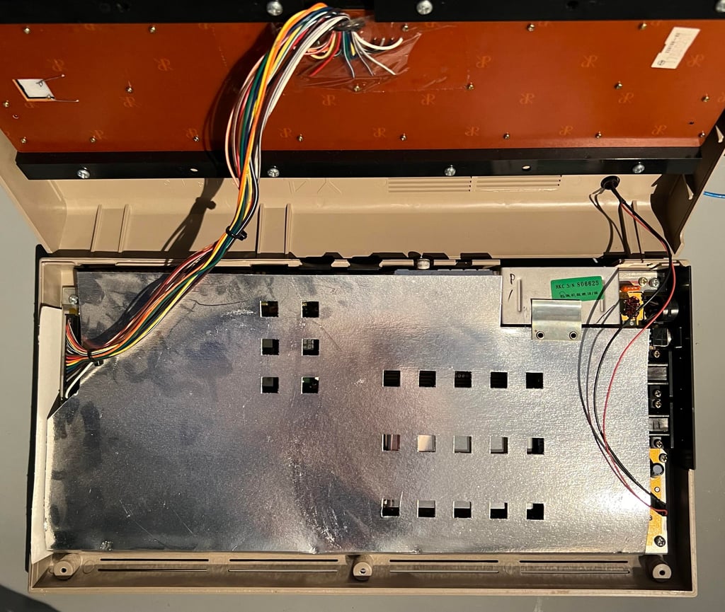

Note that the cardboard RF-shield has no purpose in modern age. Actually, it serves a negative purpose: encapsulating heat. So the plan is to remove the RF-shield (but it will be sent to the owner for nostalgic memories). Lifting the RF-shield reveals the PCBA mainboard. And, oh my, it looks perfect. I have seen quite a few Commodore mainboards, but I think this is the most clean PCBA I have ever seen. And this machine is over 40 years old...
Both the keyboard- and LED connector are lifted to release the top cover.
To free the mainboard PCBA from the bottom cover the seven screws are removed.
Exterior casing
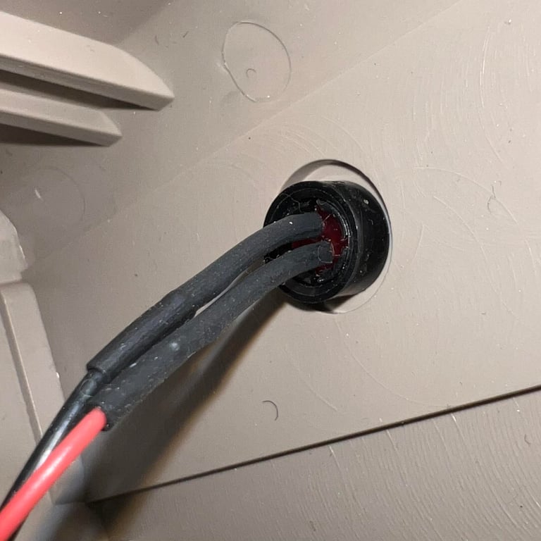
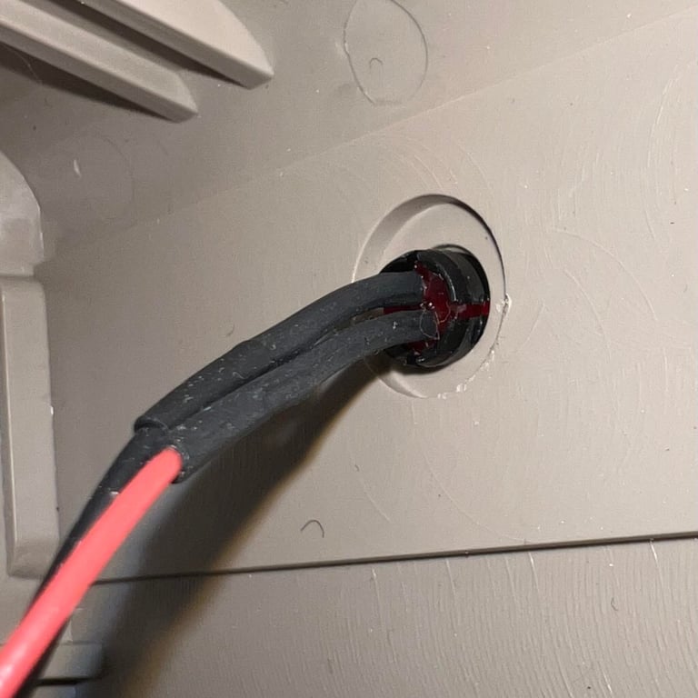
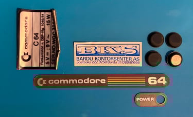
The top- and bottom cover appears to be in good condition. There are some markings, small scratches and minor yellowing - but otherwise no signs of any damage. Before starting the cleaning process all the badges and stickers are removed. First thing to do is to removed the LED from the top cover so that the "POWER" badge can be lifted.
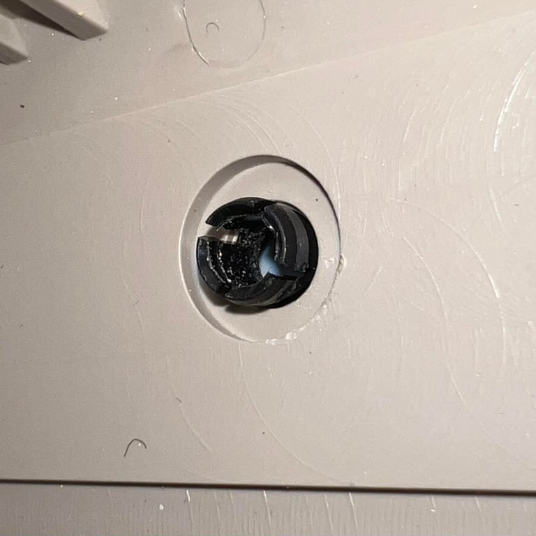
To remove the LED the small plastic ring is removed first from the underside of the top cover. Then the LED is pushed out of the plastic holder by applying a firm force from the topside of the cover to the underside. The LED will then pop out of the plastic holder. Finally the plastic holder itself is "squeezed and pushed" from the underside towards the frontside. Below are some pictures from this operation.
The badges and stickers are removed by using a sharp scalpel (and some iFixit tools) while carefully applying some hot air from a hair dryer. None of the stickers or badges were damaged during the process. Note that the four rubber feets are also removed. The reason for this is that these rubber feets can be damaged during the retrobright process (they can get very sticky).
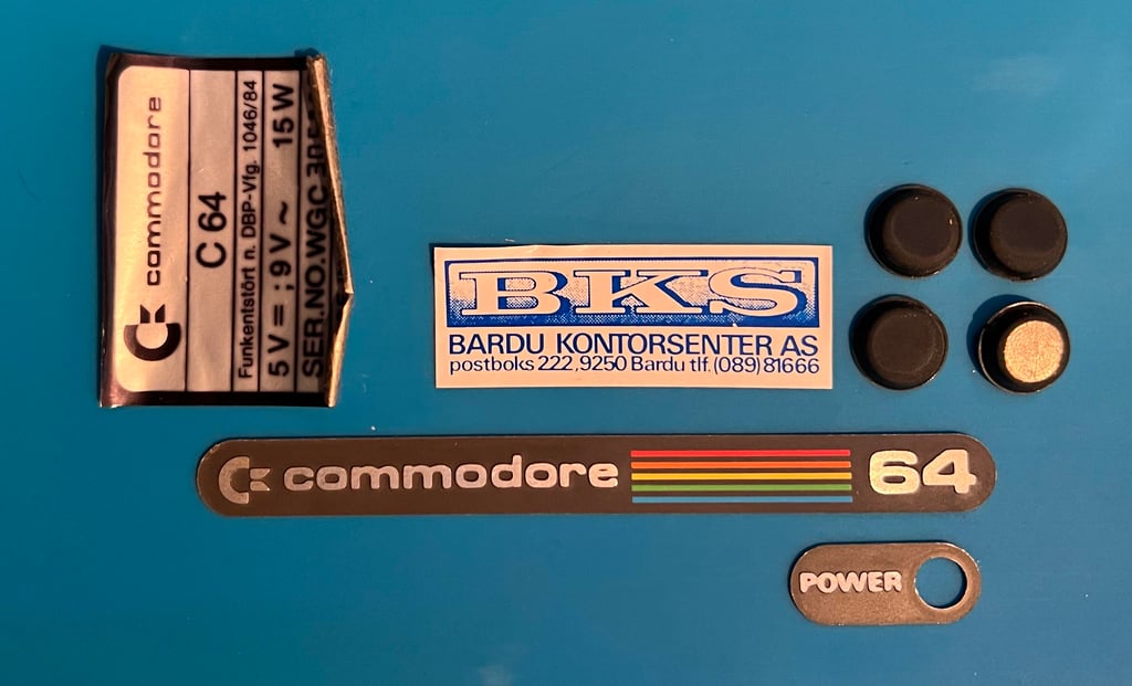
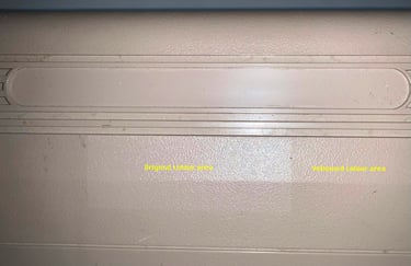
As mentioned the covers are not very yellowed. When the "BKS" sticker was removed the original colour appears. We can use this as a reference for how well the retrobrighting is successful or not. See picture below before cleaning and retrobright.

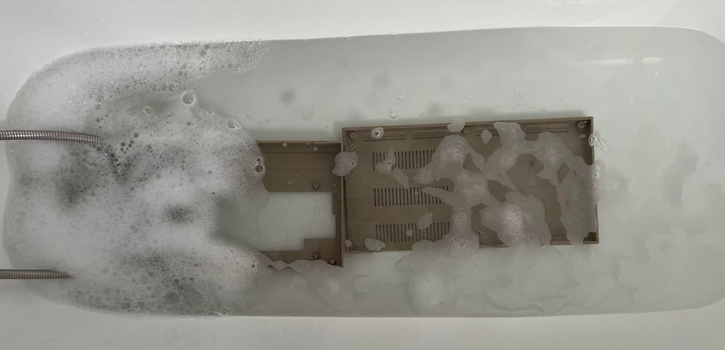
Before doing retrobrighting the top- and covers need to be clean - very clean. If there is any fat or grease on these while doing retrobright chances are that the retrobrighting will not be as successful as it should. So the first thing to do is to let the covers take a bath in mild soap water for about 48 hours. After this bath the remaing marks are removed with more soap and eventually some isopropanol.

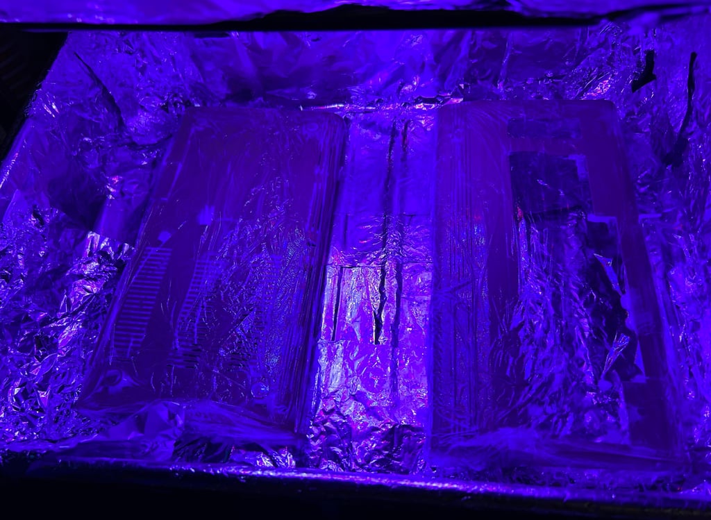
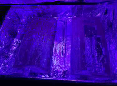
With all grease and marks out of the way it is time for retrobright. You could argue that this is not strictly required since the covers are not very yellowed, but I still think that they could benefit from it. So both the top- and bottom cover are covered with 12 % hydroperoxide cream, cling wrapped and placed in UV light for 12 hours. About every hour fresh 12 % hydroperoxide cream is applied with a soft brush.
The result from the cleaning and retrobrighting is very good. There are some signs of use at the bottom cover which is not possible to remove, but other than that I think it looks very good. Notice that the "BKS" sticker is not in place yet. I leave this to the owner of the machine to place. The sticker is prepared with some double sided tape so it can be placed anywhere the owner wants.


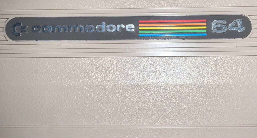
You can still see the area where the sticker was placed, but it is now marginal. I think you need to look very closely to see the difference in colour now. Compare the picture below of the badge area with the picture of the same area previously in this chapter.
Keyboard
As previously mentioned the keyboard appears to be in good condition. Yes, there are some keys missing (and some broken plungers) but other than that I can not see any damage.
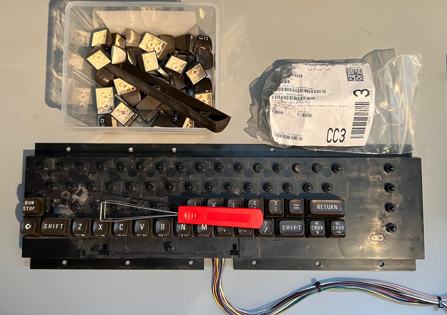
First, all the keycaps are removed. To remove the keycaps it is highly recommended to use a keycap puller. This will reduce the risk of breaking any of the plungers (and is probably the most effective way). Note that beneath each keycap a small spring is attached, and that beneath the spacebar a special spring is used. So it is good practice to keep the spacebar spring in a separate plastic bag while doing refurbishment.
There is quite some dust and grease on the keyboard, but this is normal after almost 40 years of age.
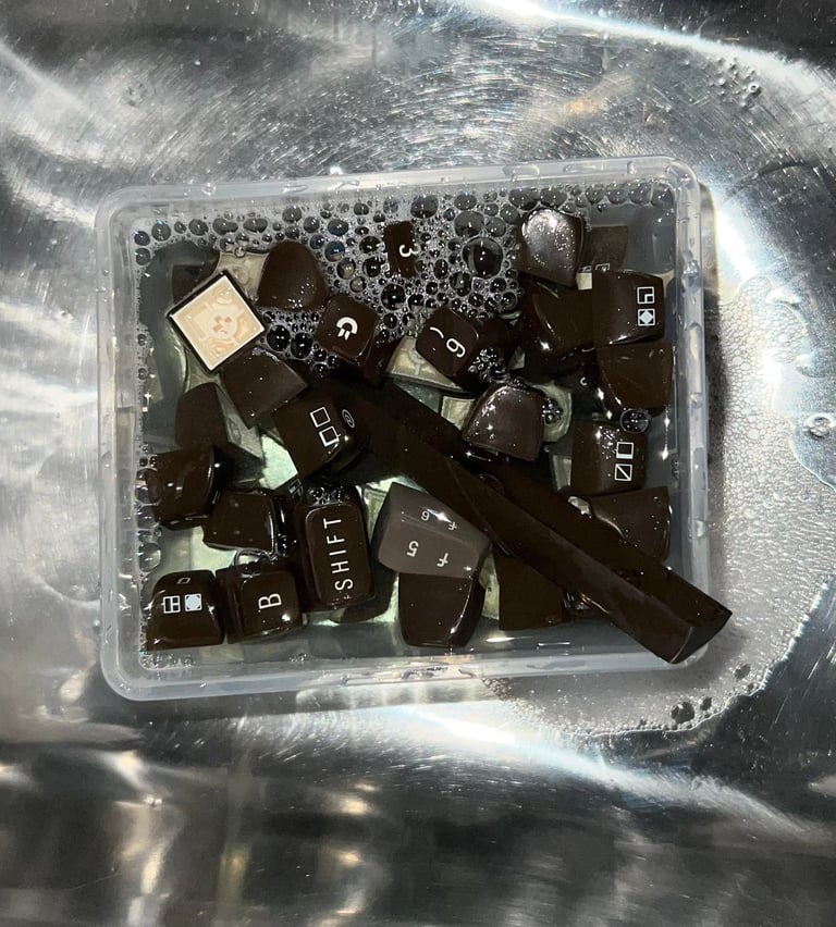
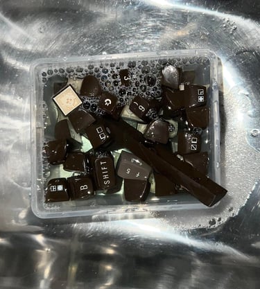
"It´s time to take a bath!" - all the keycaps are placed in a box of mild soap water for about 24 hours. This will remove most of the fat and grease without damaging the keycaps.
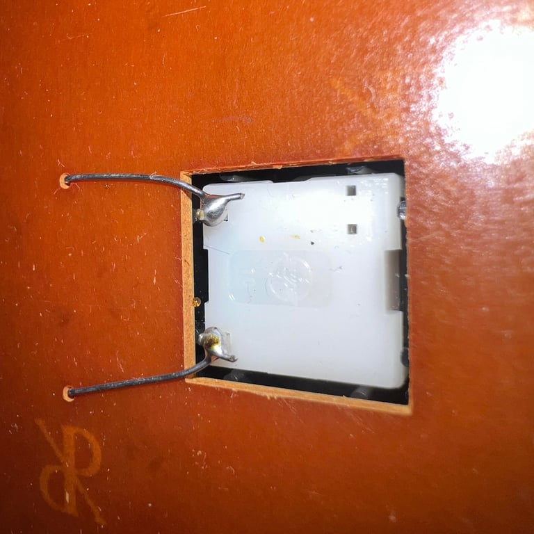
Next step is to remove the SHIFT-LOCK key. This is done by first desoldering the two uninsulated wires at the back of the keyboard. Then the SHIFT-LOCK is pushed firmly from the backside of the keyboard towards the front. This will make the SHIFT-LOCK key pop out.
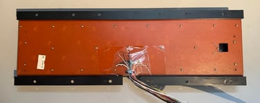
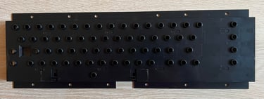
All the screws are removed from the backside of the keyboard.This will separate the keyboard PCB from the plastic holder (and all the plungers).

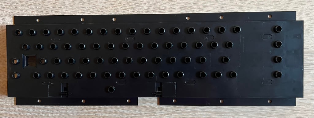
The plastic holder is cleaned properly with mild soap water. After cleaning it looks brand new (!)
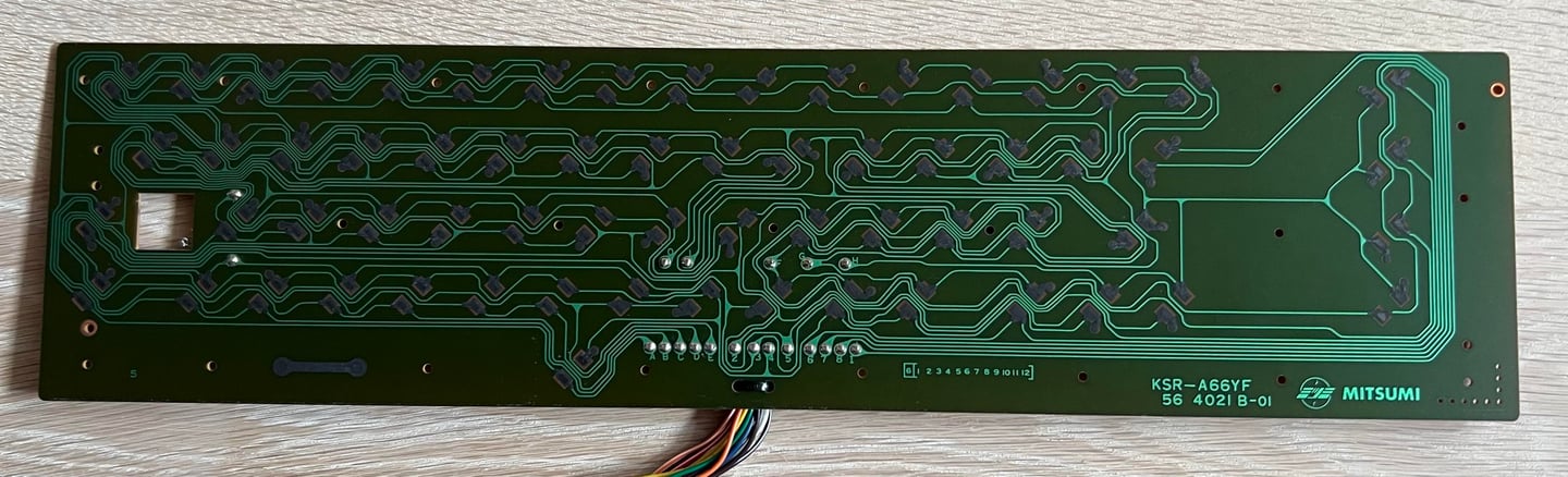
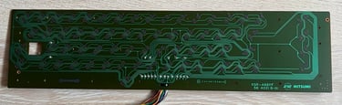
The keyboard PCB is a standard Mitsumi KSR-A66YF and is cleaned with some pure distilled water. I try to avoid using isopropanol on these PCBs since the pads are covered with carbon. The PCB looks to be in very good condition.
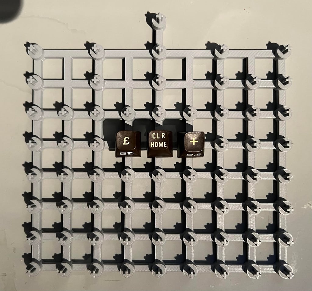
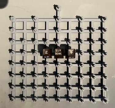
The owner of the machine order the three missing keycaps, plungers and springs from a Norwegian seller. These three keycaps are more yellowed on the top characters "+", "£" and "CLEAR HOME" compared to the rest of the keys. Retrobrighting these old brown keycaps can be a bit tricky since the front printing may start deteriorating when they area soaked in 12% hydroperoxide. But I need to do something to avoid the keycaps to look very different.
So the solution is to 3D print a keycap holder. With this holder I can place single keycaps and add hydroperoxide cream only on the top of the keycaps (and avoid the printing on the side). Note that the design of this holder/mount is not my own but downloaded from Thingiverse (Commodore KeyCap mount by kbotragyi). Below is a picture of the new 3D printed mount. The keycaps don´t look very yellowed on the picture, but they are.
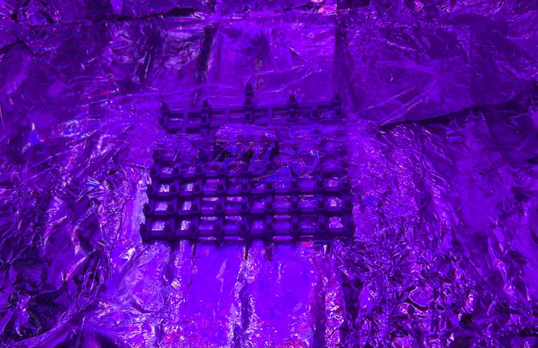
The three keycaps are applied 12 % hydroperoxide cream and exposed for UV light for about 10 hours. Hydroperoxide cream is added at regular intervals (about every hour) to avoid the cream to dry out.
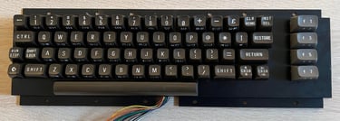
After retrobrighting and cleaning the keyboard is re-assembled. The result is very good. The keyboard looks as new (?).

Mainboard
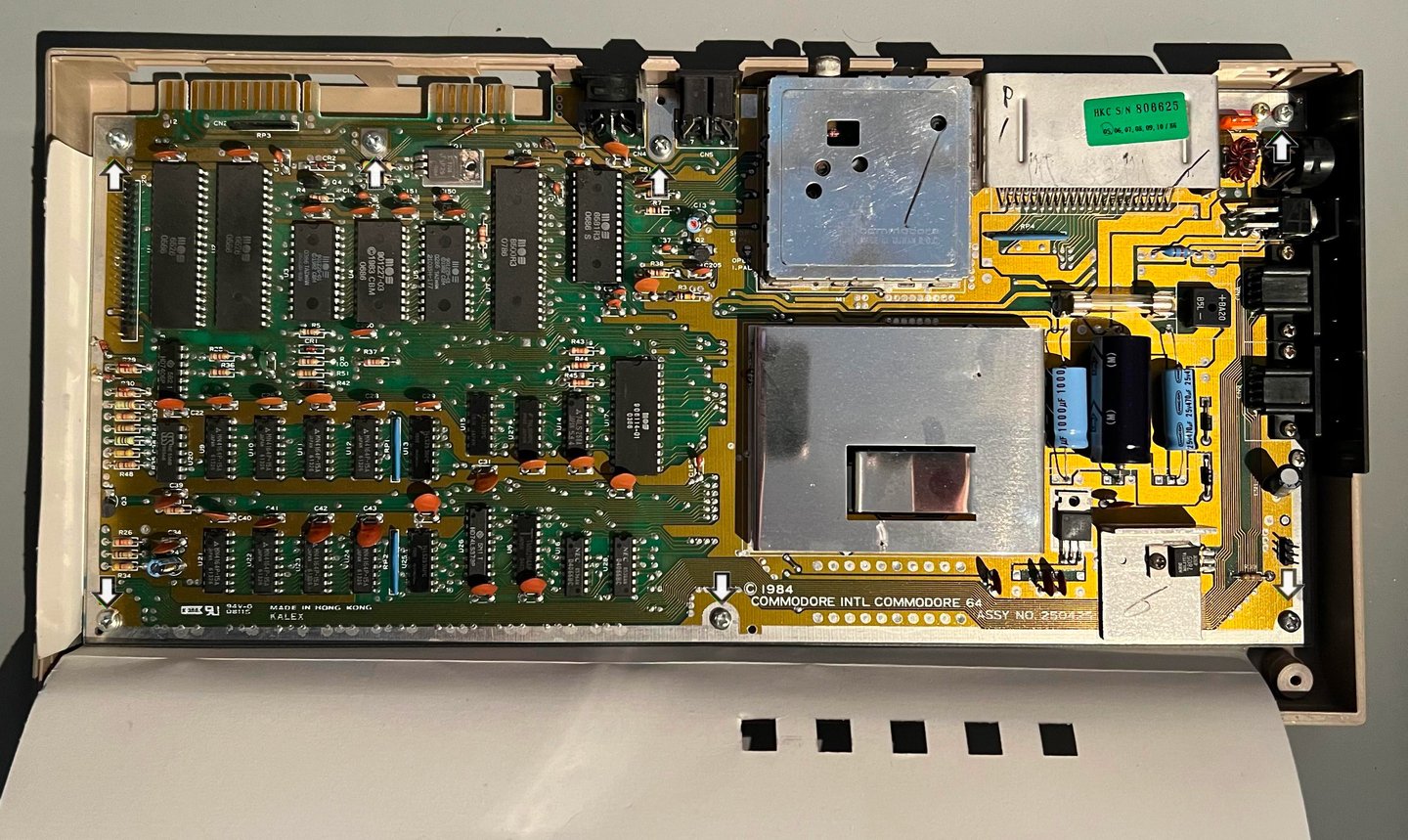
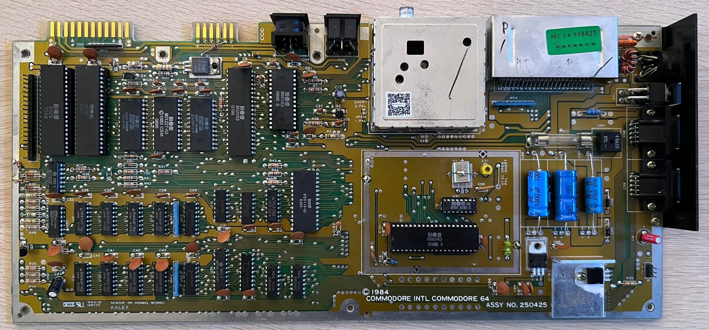
This Commodore 64 is equipped with an Assy 250425 P/N 251470-01 Revision B mainboard. These mainboard are often referred to as "longboard" as they are larger than the later Commodore 64 mainboards.
As previously mentioned this mainboard is faulty: some of the directions (LEFT/RIGHT/UP/DOWN) is not working on joystick port #2 so repair is required.
Visual inspection
Holy moly... this PCBA looks... pristine! There are only some minor dust bunnies, but otherwise it looks almost like new. I am struggling to understand that this mainboard is actually over 40 years old.
So, the idea that that the reason why the joystick port #2 was not fully working due to corrosion is... eh... yeah... not a chance. There is absolutely no sign of corrosion here. Take a look at the RF-shield on the VIC-II area and the RF-modulator can: you can almost mirror yourself in it.

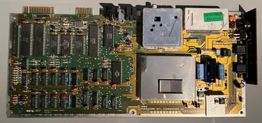
Only the VIC-II and the SID are socketed. There are no signs of rework. In the table below the main chips are listed (before refurbishment - some may be changed during repair if required).
As can be seen from the table below most of the custom MOS chips were produced in the winter of 1986. So it I would assume that this machine was sold sometime during the same year that Lionel Richie gave us "Say you, say me" and Tom Cruise starred in "Top Gun".
Checking the voltages
For the Commodore 64 to work flawlessly all the different voltages need to present and within acceptable tolerances. A detailed article on the subject can be found in the HOWTO - Checking the C64 voltages. In the table below all the measures voltages are listed (this list will also be updated after refurbishment). All the required voltages are present and within tolerances, so there are nothing obvious wrong in that area. NOTE: for those who follow my refurbish project you may notice that many of the voltages appear lower than seen before. The voltages are completely fine, but I am now using a modified C128 PSU which outputs a bit lower voltages - but it is well within tolerances.
Initial testing
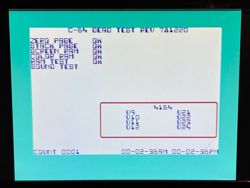
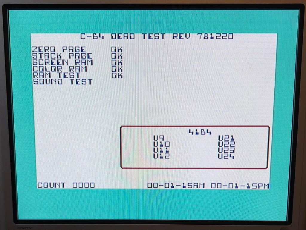
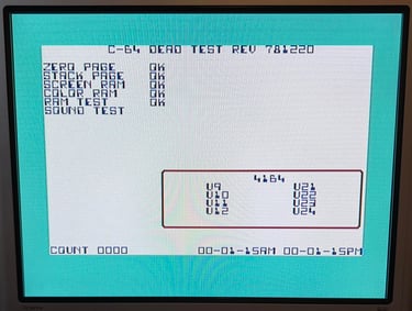
The machine is supposed to be in working condition except for the missing directions registered from joystick port #2. A quick check with the Dead Test cartridge shows that the main functions are working (a complete test will be done after repair and refurbish).
Checking the joystick port
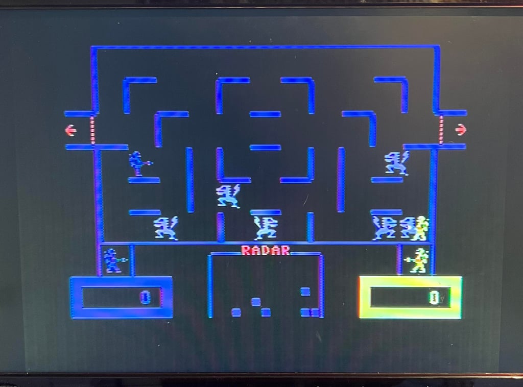
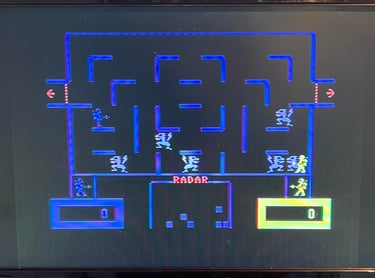
To check the joystick port #2 a game is loaded: Wizard of Wor from cartridge. It quickly becomes obvious that there is something wrong; the LEFT and DOWN direction is not working. The other directions UP/RIGHT/FIRE works fine. NOTE: all the keys on the keyboard works when pressed. This is important information as the joystick port share some of the pins on the CIA #1 chip with the keyboard.
Mainboard - Repair
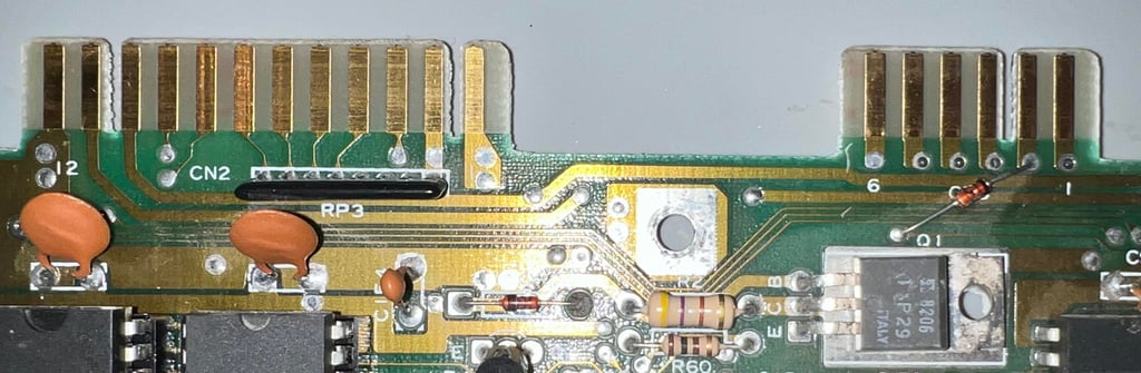
Re-soldering the joystick port
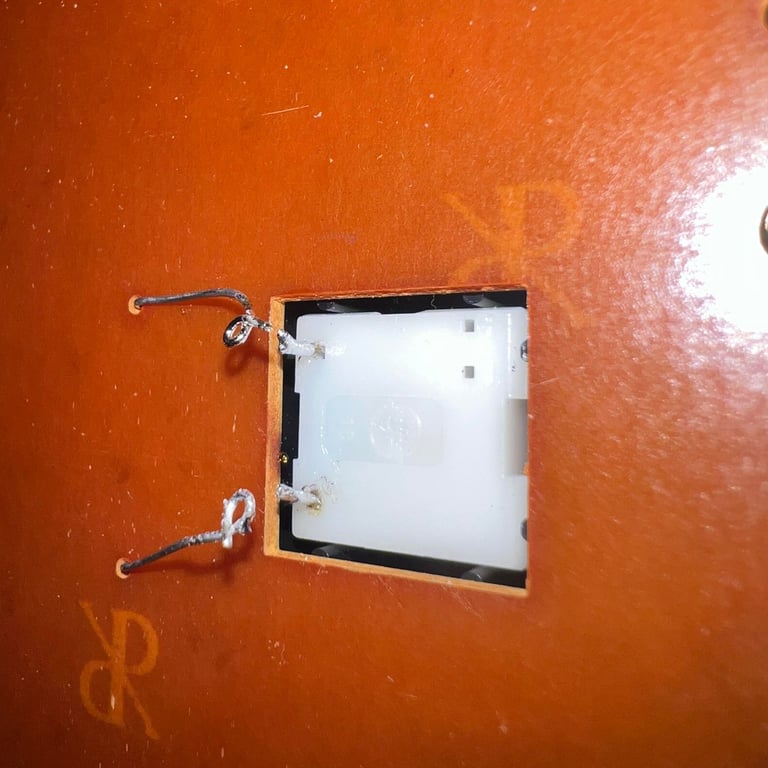
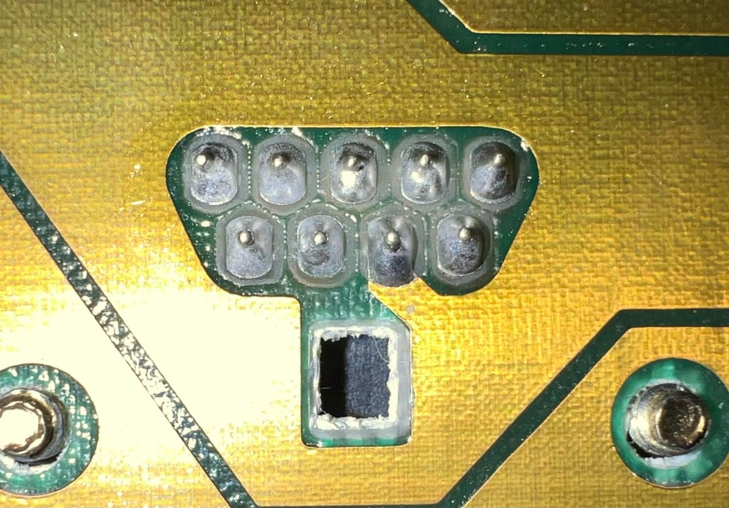
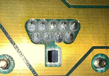
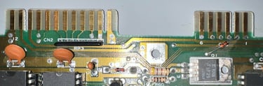
It is not uncommon that the solder points connecting the joystick port to the mainboard needs to be re-soldered. The joystick port(s) are heavily used and considering that the solder is 40+ years some fresh solder will do good. Nevertheless, I do not expect this to be the fault - and it is not. But at least the new solder will help on keeping the joystick port in contact with the mainboard. Below is a picture of the re-soldered pins.
Checking the connectivity
Next step is to check the connectivity between PIN # 2 (JOYB1) / PIN # 3 (JOYB2) and PIN # 3 (PA3) / PIN # 4 (PA4) on the MOS 6526 CIA #1 chip. See schematics below. Note that PIN # 19 and PIN #18 from the keyboard connector is also connected to the same CIA #1 pins.

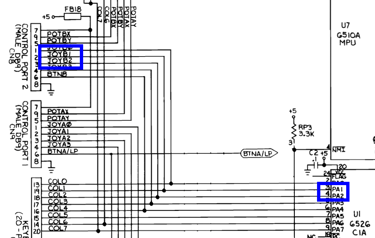
Both the DOWN (JOYB1) and LEFT (JOYB2) are connected to PA1 and PA2 on the CIA #1. So there is nothing wrong with the connectivity. As can be seen from the picture below the connectivity is tested end-to-end with a DB9 joystick connector (with all wires exposed) applied to the port.
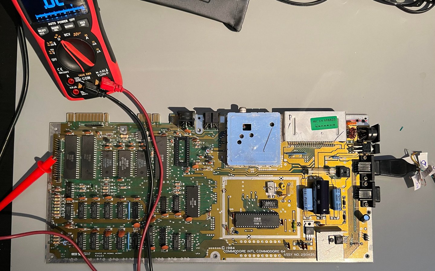
Checking the voltage levels on the CIA #1
Since we know that there is continuity between the JOYPORT #2 and the CIA #1 the next step is to check the voltage levels on pin # 3 and pin #4 on the CIA #1 chip. These should be +5 V (HIGH) in idle mode, but pulled to GROUND (LOW) when the joystick is pushed in LEFT and/or DOWN directions. Using the oscilloscope connected to PIN #3 and PIN #4 in turn on the CIA #1 shows that these pins are pulled LOW when the joystick is pushed in LEFT and/or DOWN directions. Also, the idle voltage is + 5 VDC. So there are no issues with the voltage levels. Check video below.

Checking the $DC00 register
Noticed the small little LOW spot on the oscilloscope when the joystick is idle? This is when the Kernal ROM is writing to the $DC00 each 1/50 second. When the Kernal ROM writes a LOW to the individual bits in register $DC00 the current COLUMN is active and the ROWS can be read on $DC01. And we do know that the keyboard works, so can it be that the MOS 6526 CIA #1 is marginal? As in that the PORT A can be written internally, but it can not be read?
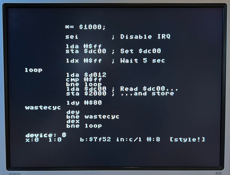
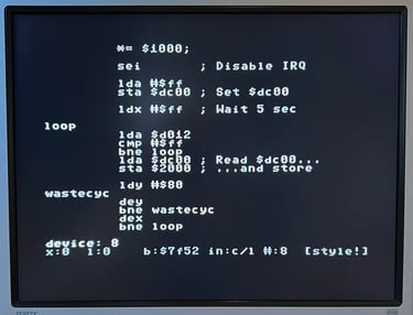
I could just desolder the CIA #1 and check with a known good working chip, but I want to verify my hypothesis first. To do that I will make a small assembly program which disables all interrupts from the Kernal, read and save the $DC00 register for a five seconds while holding the LEFT/DOWN direction on the joystick before returning to normal Kernal operation. If my hypothesis is correct we will see that the saved value of the $DC00 register is %xxxxx11x on exit. This would imply that the CIA #1 can´t read these two bits on PORTA. If the saved value in the $DC00 is %xxxxx00x then my hypothesis is wrong (the CIA #1 could potentially be faulty, but then for other reasons).
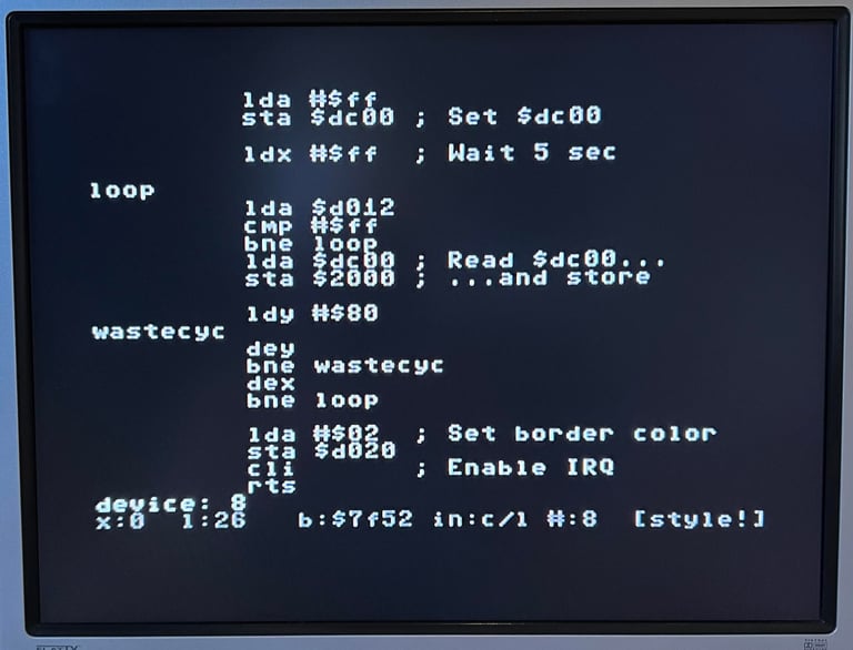
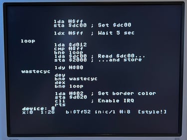
Below are some pictures from the assembly program written with Turbo Marco Pro on the Commodore 64. The nice thing with assembly programming is that it gives the possibility to see what is happening inside the ICs registers.
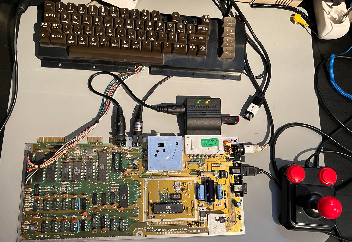
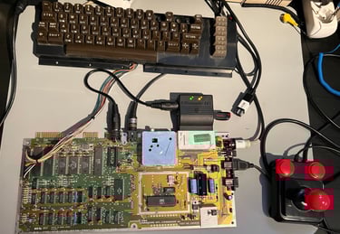
The keyboard is re-attached and the Ultimate II+ is used to emulate a floppy drive to load Turbo Macro Pro. Also, the Ultimate II+ is used to emulate the Super Snapshot cartridge with contains a machine language monitor to browse through memory. See picture for setup.
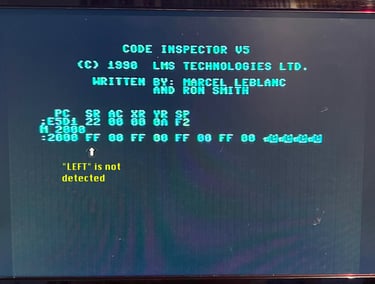
Before running the test on the machine the program (and setup) has been tested on a known working Commodore 64. The program dumps the value of $DC00 to $2000 before exit. On a working machine the expected value of $2000 is %11111101 ($FD) for "DOWN" and %11111011 ($FB) for "LEFT". And as the pictures below shows this is the case - so we know that the home made program works on a working Commodore 64.
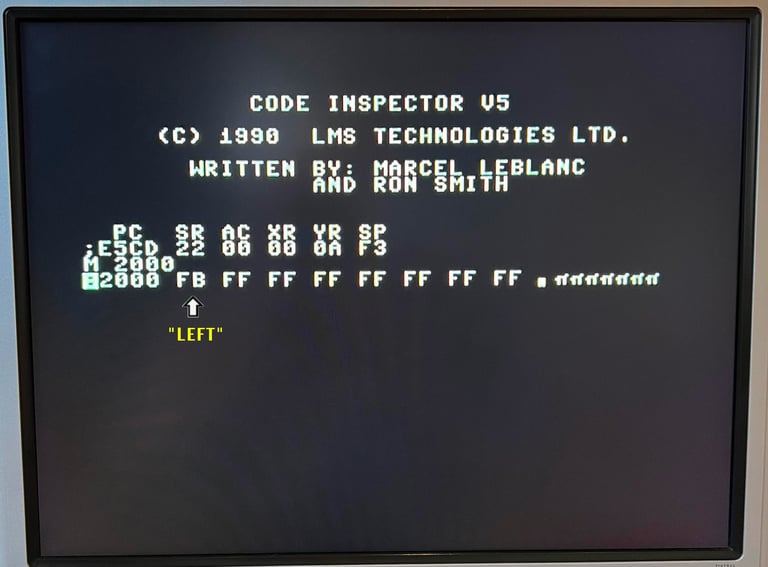
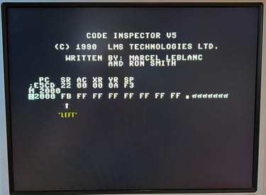
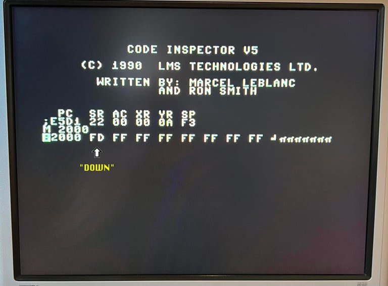
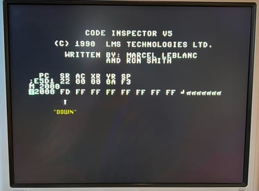
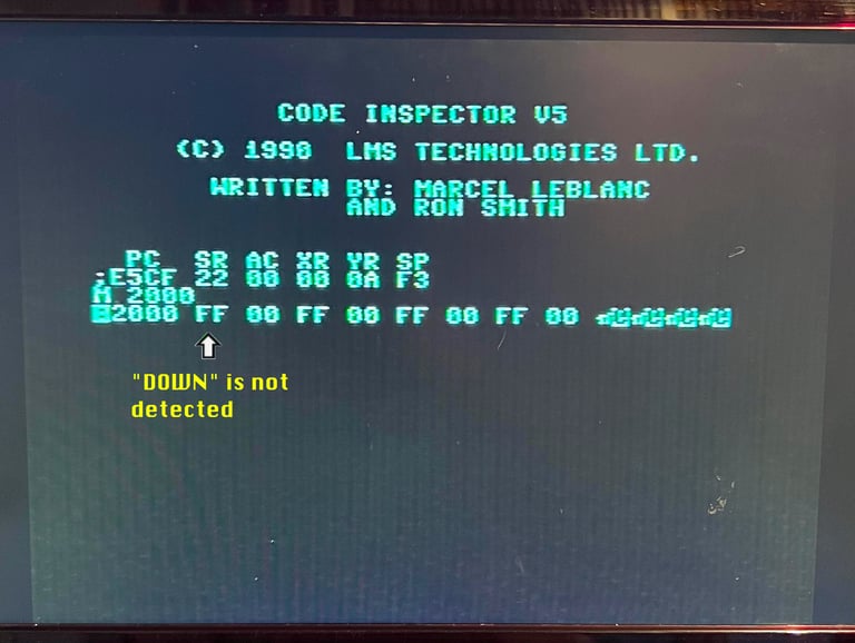
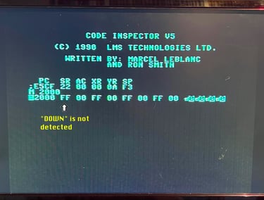
Ok, so now we know the program works on a working machine. But will we get the expected result on the faulty machine? If the CIA #1 is only able to write to bit #1 and bit #2 on PORTA - but not read these bits - the output on $2000 should be %11111111 ($FF) both when the joystick is pushed "LEFT" and "RIGHT". And this exactly what we see on the faulty machine (!). See pictures below.

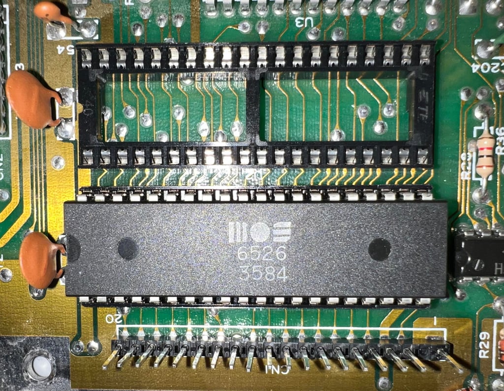
Replacing the MOS 6526 CIA #1 (U1)
We have proven that the CIA #1 is not able to read the input on PIN #3 and PIN #4 (PORTA bit #1 and bit #2). So the next step is to desolder the CIA #1 in position U1, install a new socket and test with a known working MOS 6526 IC.
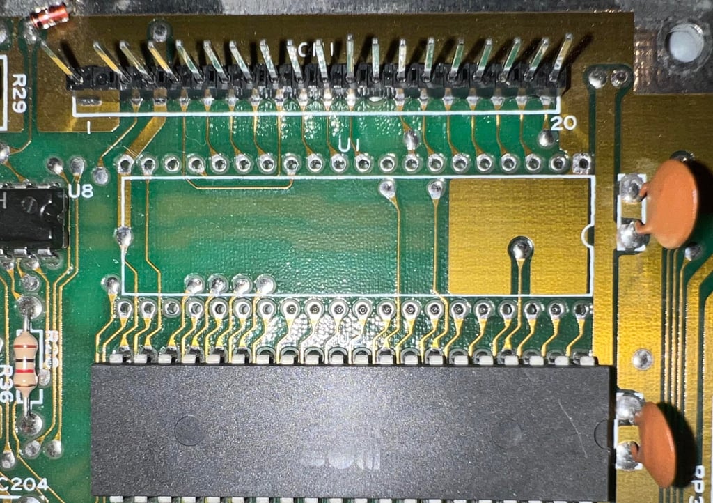
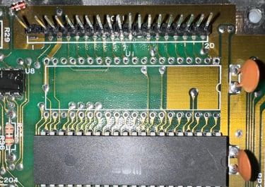
Desoldering the CIA #1 is done without any damage to traces or pads. See picture below.
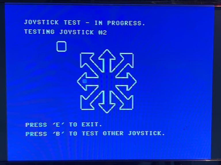
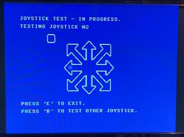
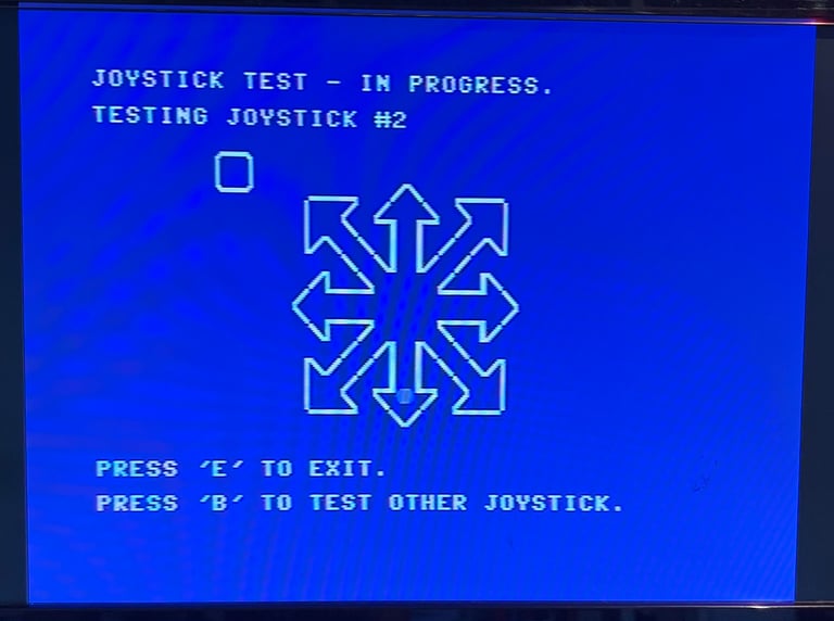
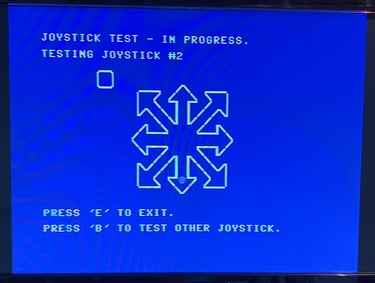
A new socket is soldered in and a known working CIA chip is installed. The result: SUCCESS! With the working CIA chip installed the joystick input is now working as it should. See pictures from the joystick test below where the "LEFT" and "DOWN" direction are tested.
Switching the CIA chips
It may be a shot in the dark - but since we know that the CIA #1 chip works partially in that it can write, but not read to PORTA, what would happen if we interchange the two CIA chips? This is more of an experiment, but the 2nd CIA is desoldered and socketed and the two chips are interchanged. The 2nd CIA is controlling the serial interface (aka the disk drive interface). The result is that the Commodore 64 now has a working joystick port #2, but the machine struggles with loading. It does load directories and some software, but when it comes to loading multiple files disks it fails. Anyhow, it was worth the attempt and it is always nice to have ICs in sockets.

Mainboard - Refurbish
After the repair the refurbishment continues. Note that there can be more repair required, but that not that I know of at the moment.
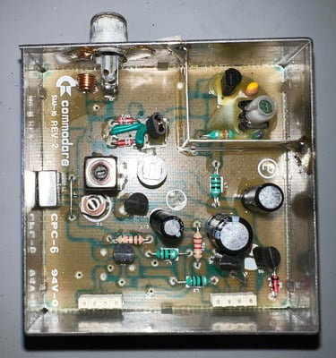
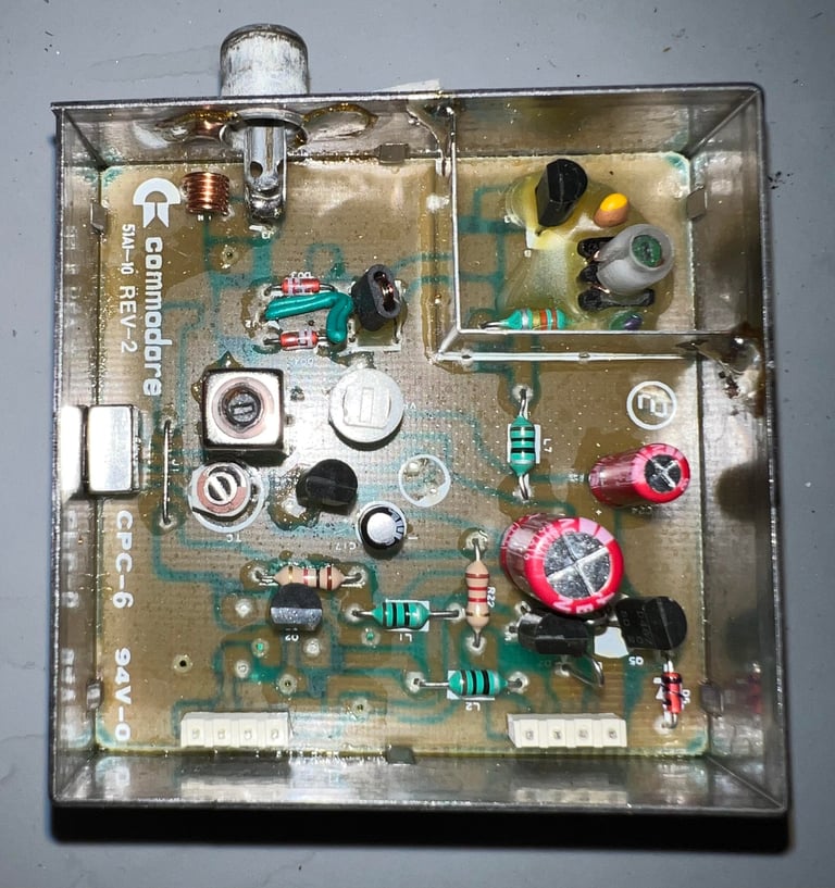
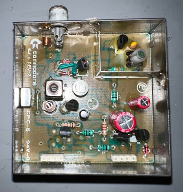
Replacing the electrolytic capacitors - RF modulator
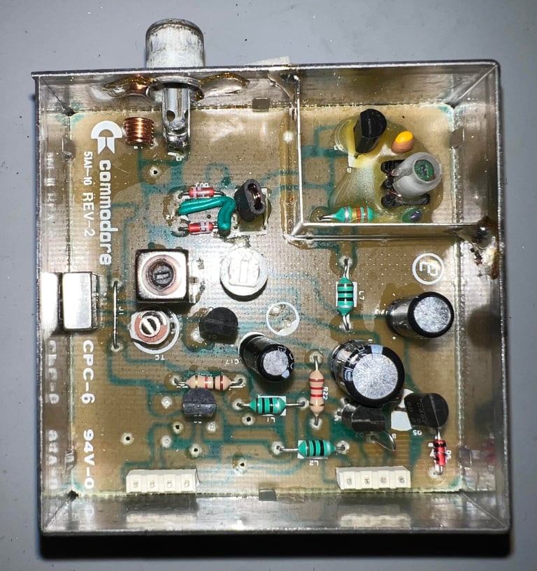
This C64 breadbin is equipped with a Commodore RF-modulator with P/N 251697-02. According to the capacitor list this RF-modulator contains three electrolytic capacitors: 1 x 10 uF [10 V], 1 x 100uF [16 V] and 1x330 uF [10 V]. It is an endless discussion in the Commodore community if it is required electrolytic capacitors. They seldom go bad. But I think it is good practice to do so as part of refurbishment. These capacitors are long past their expected life span.
To replace the electrolytic capacitors in the RF-modulator the modulator container needs to be desoldered which is not trivial. It is not that it is difficult, but you need to do it right to avoid any damage on either mainboard or the RF-modulator itself. Please see the HOWTO article on desoldering the RF-modulator for details how I do this.
The RF-modulator metal container is desoldered without any damage to either modulator or mainboard. Ses picture below.

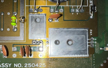
The RF-modulator is opened and the three electrolytic capacitors are replaced. No damage to either pads or traces. See pictures below. The picture to the left (top) is the original capacitors and the picture to the right (bottom) is with the new ones.
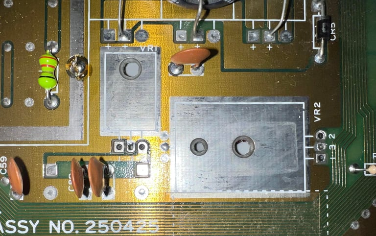
Replacing the 78xx voltage regulators
The power supply is providing + 5VDC and 9VAC. From the 9 VAC an additional +5VDC and +12VDC is generated. The purpose of these additional voltage sources can be studied in the the HOWTO article Checking C64 voltages. In short, these additional voltage sources are used to supply the custom SID and VIC-II chip. And it is crucial that these voltages are within range - to not damage these ICs. Therefore it is good practice to replace these 40 year old voltage regulators with new modern replacements.
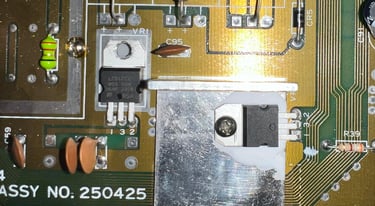
Notice that the 7812 (12 V regulator) is not mounted on a heatsink. This is from factory. Only the 7805 voltage regulator is mounted on a heatsink.
Below are some pictures from the desoldering and the installation of the new voltage regulators.

Replacing the electrolytic capacitors - mainboard
The assy 250425 mainboard is equipped with six capacitors according to the capacitor list. Commodore is famous for using "whatever was available" when assembling their great machines. And this is also the case with this very machine. The capacitor C19 is supposed to have a capacitance of 2200 uF, but on this one is equipped with a capacitor of whopping 4700 uF (!). This is "wrong" according to Commodore´s own reference manuals where C19 is stated to be 2200 uF [16V] in both the BOM for assy 250425 and in the schematics 252469 (used for that assy). See schematics and tables below.
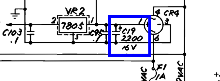


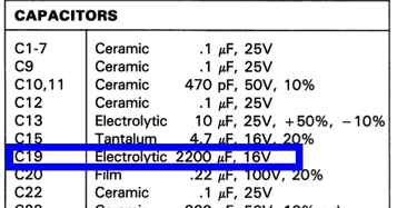
You could argue that keeping the 4700 uF would make it more "original", but I do not agree. I see it more like fixing a mistake done by Commodore in the autumn in 1985. Almost 40 years later the fault is fixed - a real 2200 uF is installed for C19.
Below is a picture of the mainboard after full recap. Note that the C24 capacitor is replaced with a capacitor with somewhat higher voltage rating 63 V instead of 25 V. This has no effect on the performance of the machine (also, C24 is used in combination with the reset circuitry 556 timer (U20)).

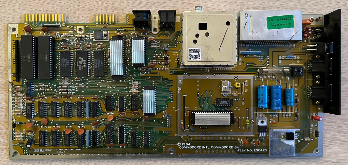
Adding heatsinks on custom ICs
In an attempt to reduce the probability of the custom chips from failing heatsinks are added on the most valuable ICs. Heat will be naturally generated during the operation of the ICs, but too much heat (or the lack of dissipation) can make the IC fail. So modern heatsinks are added to the SID-, CPU-, PLA- and VIC chip. See picture below.
Cleaning the user- and datasette connector
So simple, but so effective. In order for the Commodore 64 to use peripherals such as modems and datasette the connectors need to be working flawlessly. But after 40 years the metal platings are often covered with fat and grease (and sometimes oxidized). To clean these connector a normal rubber eraser is used to scrub away the grease, and then clean the connectors with isopropanol. This is the most gentle way to clean these port (do not use fiber glass pen if you can avoid it - this can damage the metal plating). Below is a picture of the cleaned connectors.
Replacing the faulty MOS 6526 CIA #1
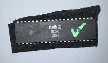
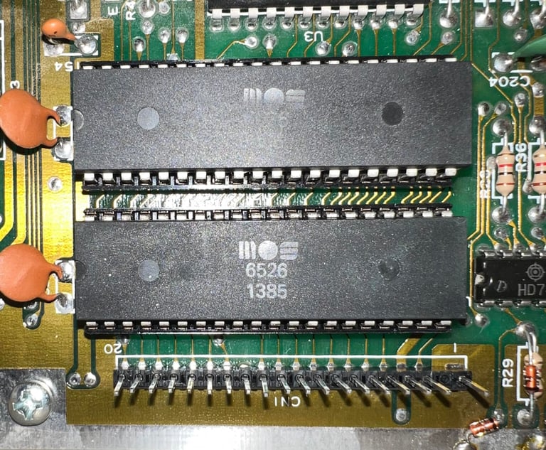
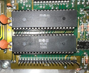
A "new" CIA chip is sourced (by the owner from a Norwegian supplier) and installed in the machine. The new CIA chip has the date code week 13 year 1985 - note that the table in the "Mainboard" chapter is updated in the notes column. Below is.a picture of the new CIA chip before installation and one where is sits together with the second CIA chip.

Testing
Proof is in the pudding - does it work?
Testing is done through two main stages:
Testing the basic functionality and chips
Testing by using the machine playing demos, games etc. accessed by both floppy and datasette to verify correct operation
Basic functionality and chips
First test is done using the Dead Test Cartridge. This test doesn´t test all the functionality of the Commodore 64, but it does test the basic functionality of the major chips such as the CIA #1/2, CPU, VIC-II, PLA, RAM and SID. As the picture shows below the test is passed.
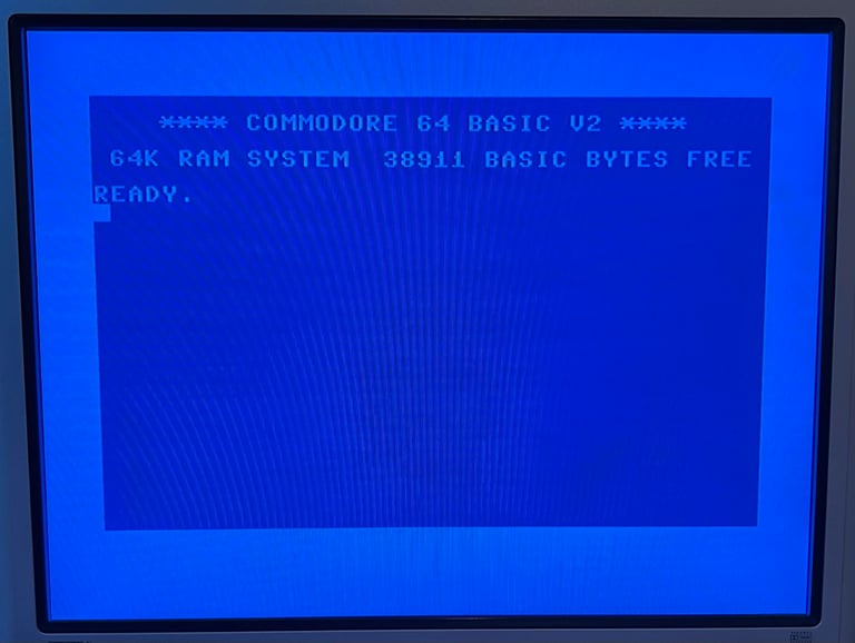
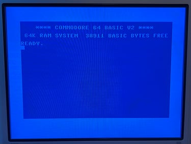
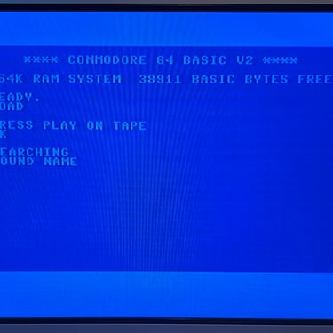
Next test is to power the Commodore 64 to the blue boot up screen and also check the keyboard to make sure all keys works as they should. The test is passed; all keys works and 38911 BASIC Bytes Free.
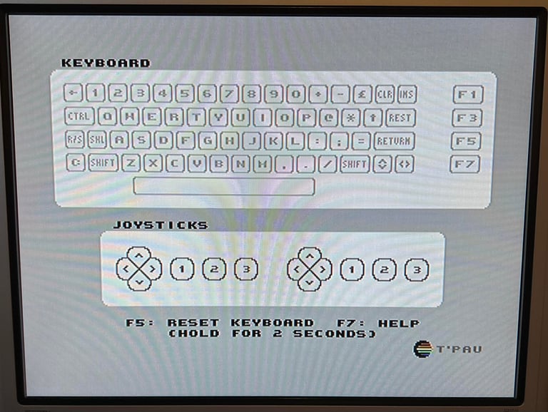
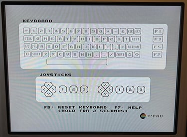
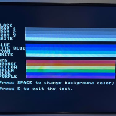
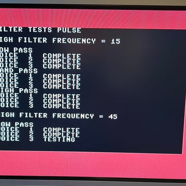
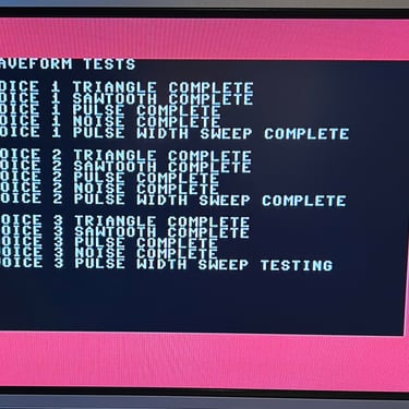
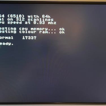
The basic functions of the VIC-II, SID and RAM is tested with 64 Doctor, Commodore 64 SID tester and MemTest64. Note that this is to be considered as basic functionality - more advanced (?) functionality such as sprite handling / collision detection / advanced audio will be tested later. But the basic tests pass without any detected faults (click to enlarge).
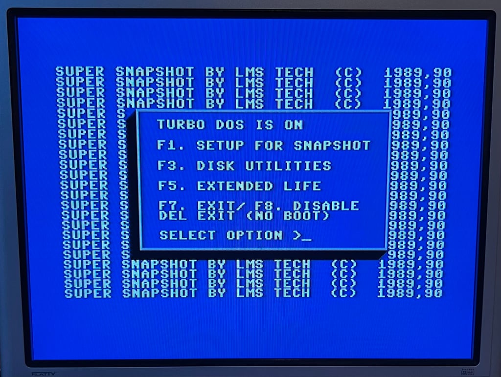
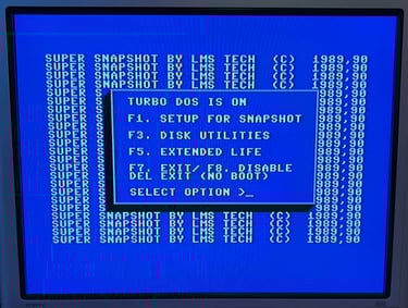
Last basic check before moving to more extensive testing is checking the cartridge. This is done by using the Super Snaphot V. Result is that the test is passed.
Extended testing
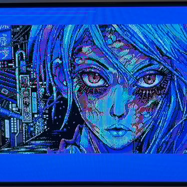
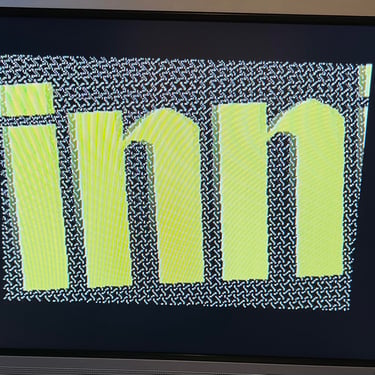
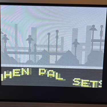
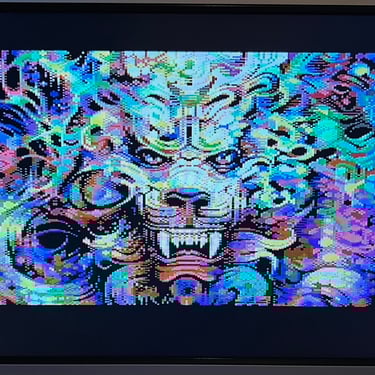
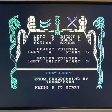
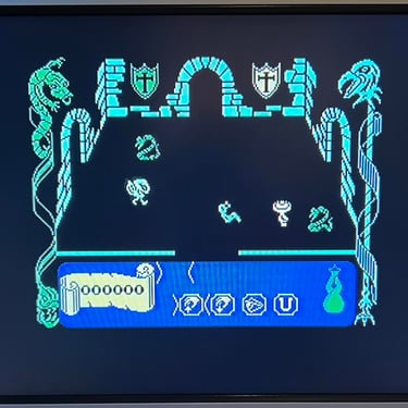
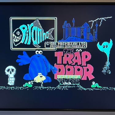
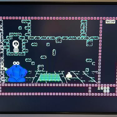
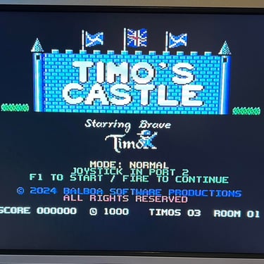
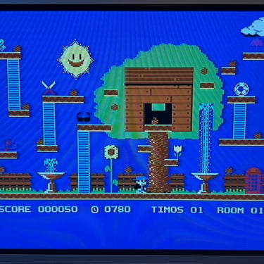
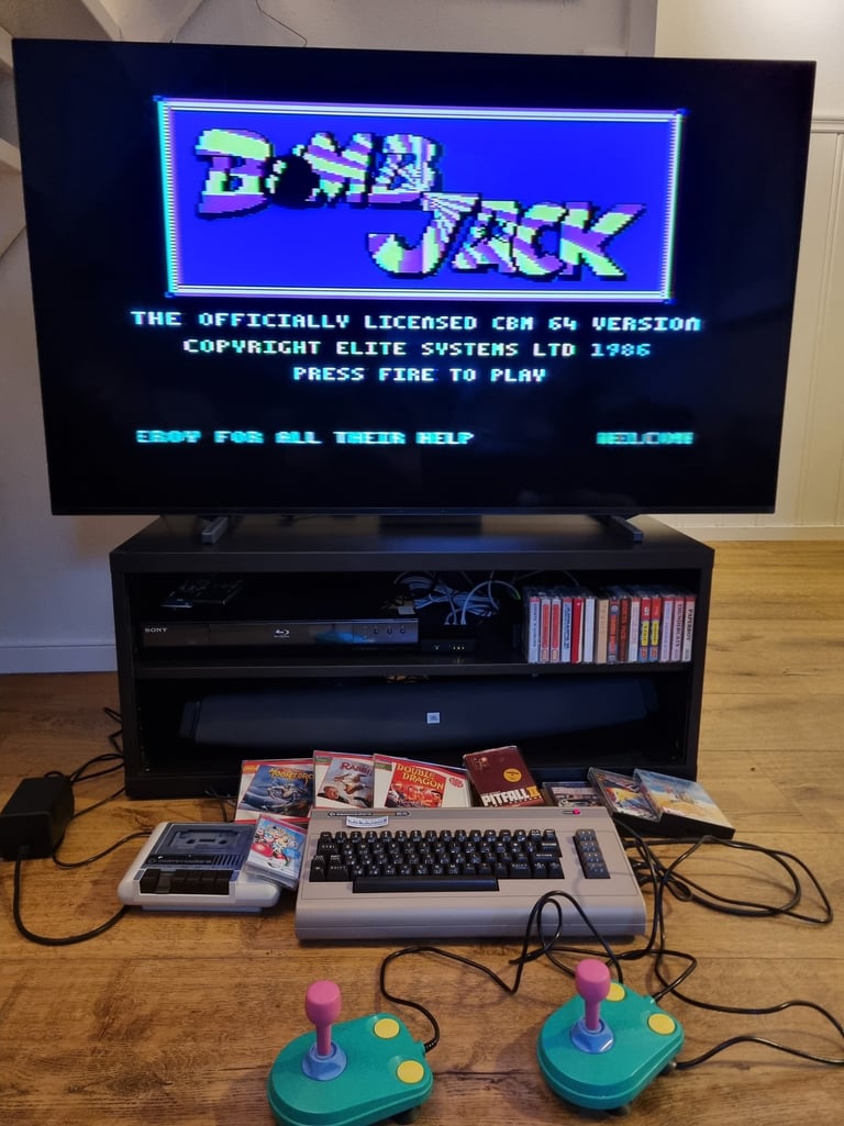
Knowing that the basic functionality of the machine works I continue the testing by using the Commodore 64 for normal operations; playing some games, watching demos, loading from datasette and floppy and using a cartridge. I can not find any issues with this machine. I also pay special attention to the video to make sure that there are no glitches in the graphics - I can´t see any abnormalities. Below is a gallery with pictures from the testing.

Final result
"A picture worth a thousand words"
Below is a collection of the final result from the refurbishment of this C64. Hope you like it! Click to enlarge!

"Are you keeping up with the Commodore? 'Cause the Commodore is keepin up with you!"
Below are some pictures of the Commodore 64 back at the customer´s home!
Banner picture credits: Evan-Amos