

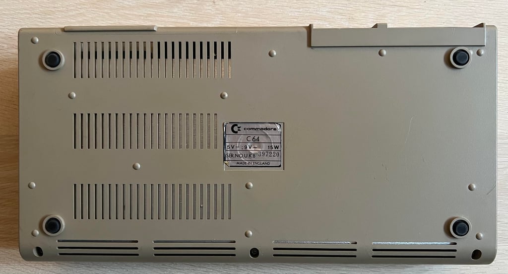
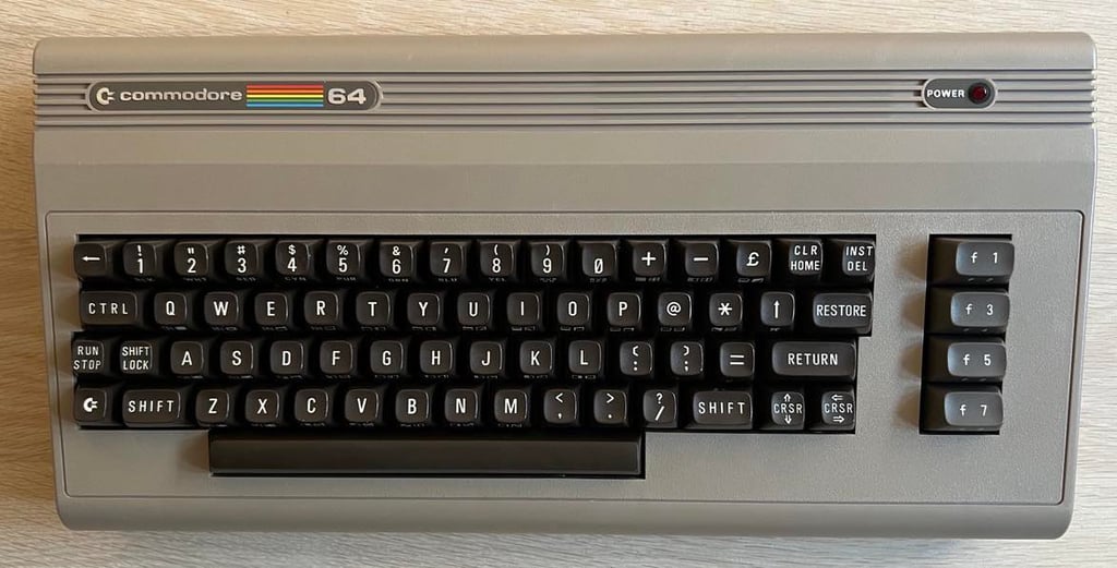
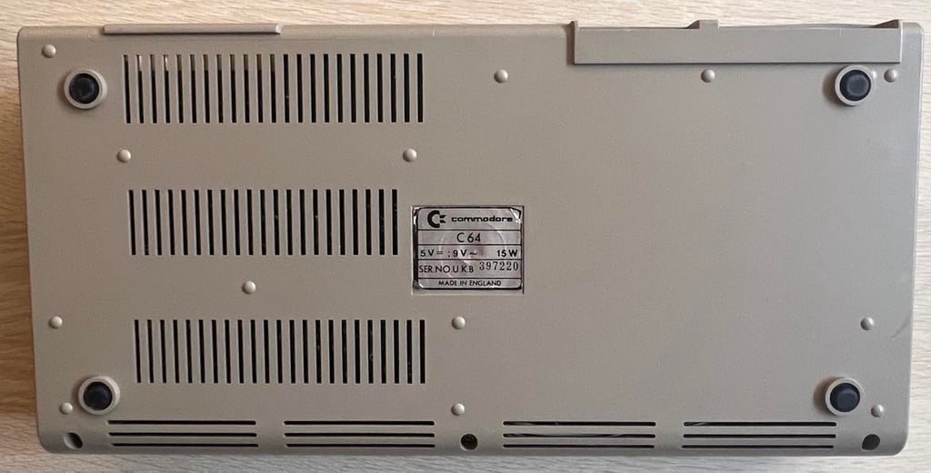
C64 Breadbin
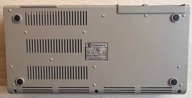
Ser. No. 397220
Assy 250407
Artwork 251137 (REV B)
Starting point
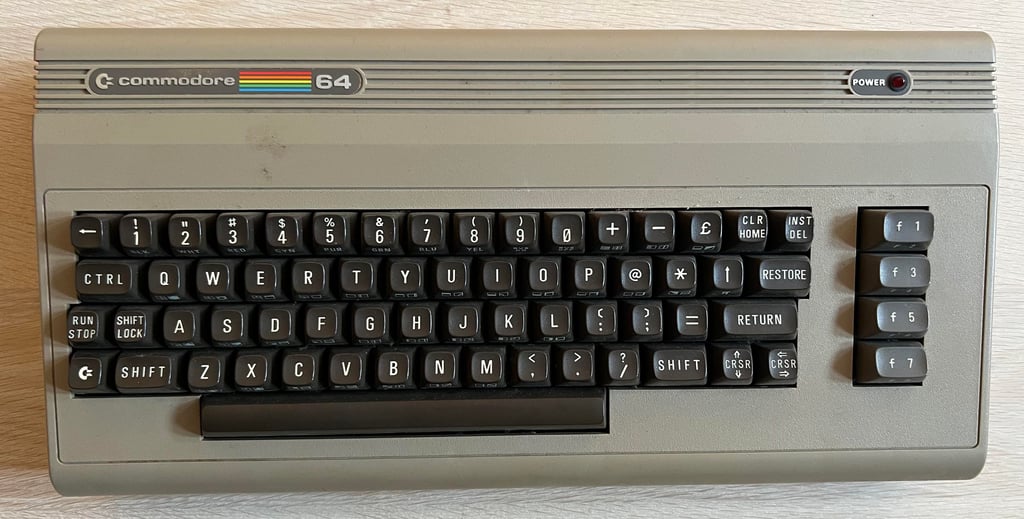
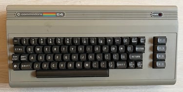
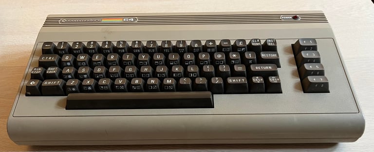
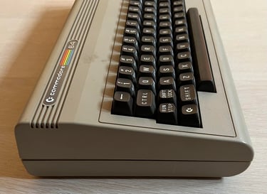
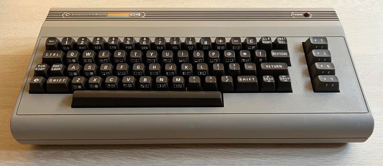
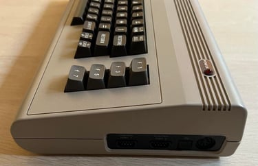
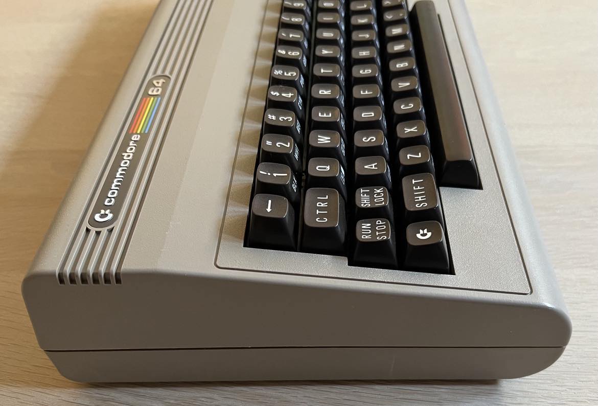
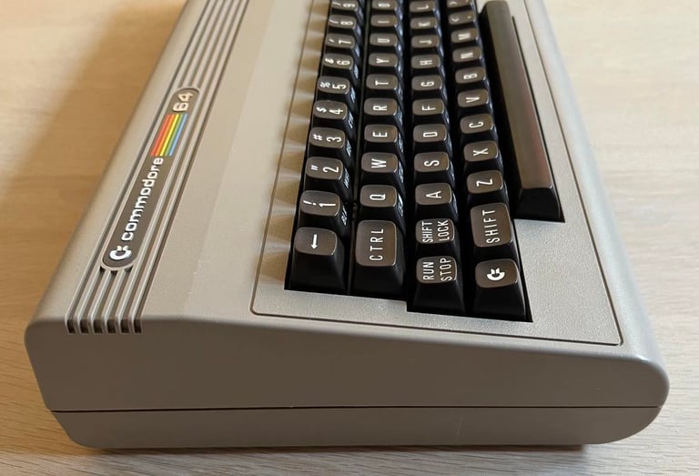
Another Commodore 64 to refurbish! And this one looks promising! It is dirty, and the casing seems to be be only partly assembled - but otherwise this machine looks quite ok from the outside. I can not see any major damage to it. I do not know if this machine works or not, but I have hopes that this will be a success.
It is not very yellowed either. It could be that only some days in the sunlight will do magic with this one.
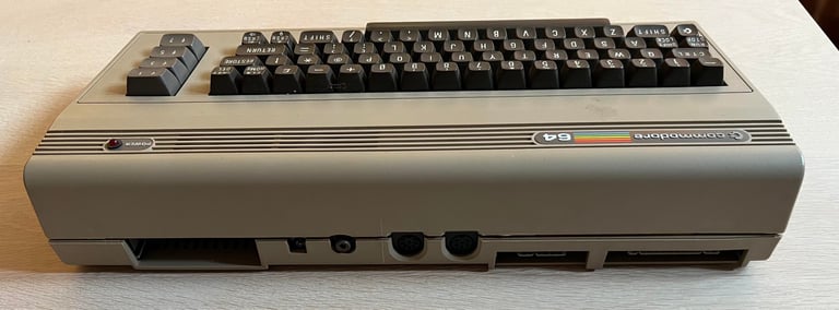
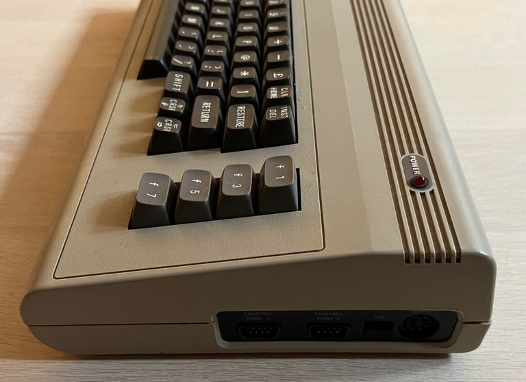
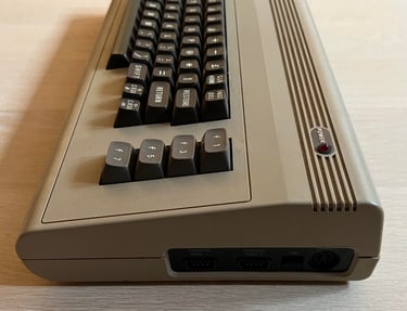
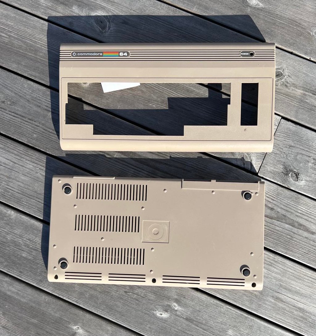
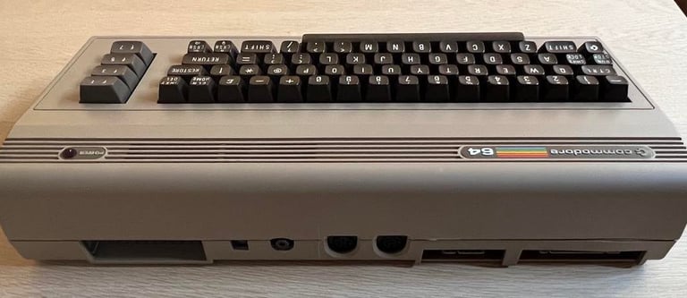
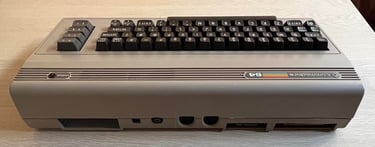
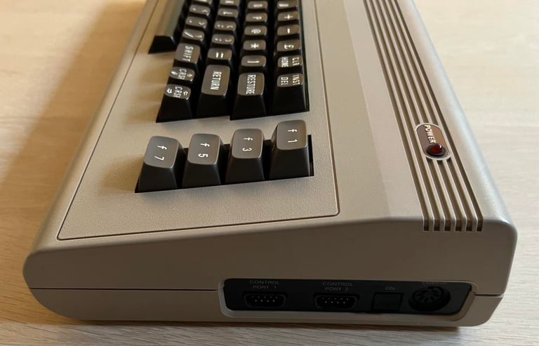
Below are some pictures of the machine before refurbishment commence.


Refurbishment plan
The refurbishment plan for this C64 breadbin (some of them in parallell):
- Clean and remove stains from the chassis
- Clean and restore the keyboard
- Refurbish main board (cleaning, checking, repairing, replacing capacitors and voltage regulators etc.)
- Recap RF-modulator
- Verify operation by testing
The plan can be updated during the refurbishment process. Sometimes I discover areas that needs special attention.
Exterior casing
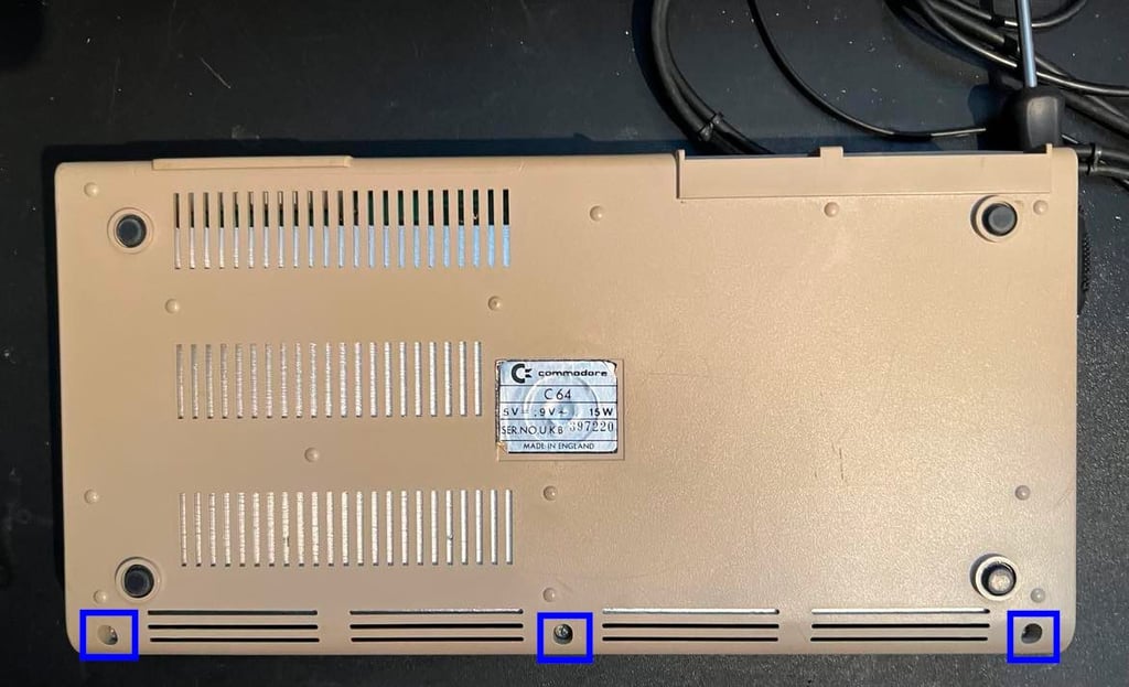
The Commodore 64 breadbin case consists of a top- and bottom cover. And they are held together by some "clips" at the rear of the top cover and three screws visible from the bottom cover. But as can be seen from the pictures in the "Starting point" chapter these two parts are not well assembled. There is a small opening at the rear where the two covers should be tightly connected. I need to fix that also.
Nevertheless, to disassemble the machine the three screws at the bottom are removed (blue squares).
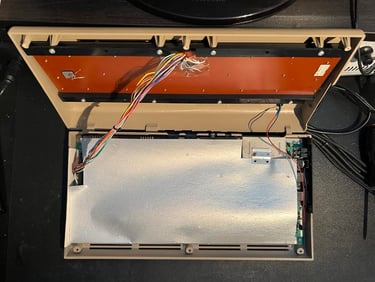
Turning the Commodore 64 and opening the top cover reveals the inside. As can be seen below a large cardboard RF-shield covers the mainboard PCB. This RF-shield will be removed as it no longer has a purpose. It will only keep heat inside the machine - which can reduced the lifespan of the chips (which is already very long).

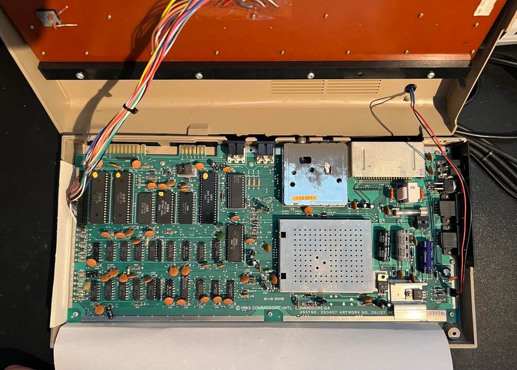
Lifting the RF-shield reveals the mainboard in all its beauty. The PCB looks to be complete and undamaged. I will investigate later if the mainboard has been repaired or modified at a later stage.

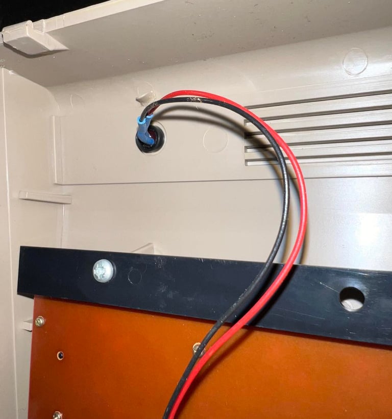
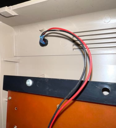
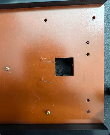
Before the top- and bottom cover is cleaned the LED is removed. This is done by first removing the small plastic ring, then pushing the LED from the front side towards the backside until the LED "pops out". Finally the the plastic LED clip is pushed from the backside towards the front side. The sticker at the bottom cover is also removed to prevent damaging it during cleaning.
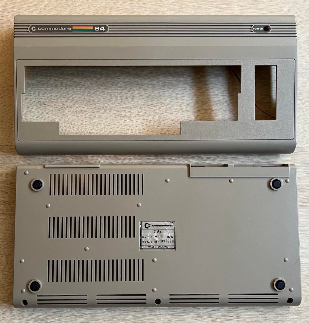
Since the weather is quite nice in Stavanger at the moment I choose to sunbright - instead of retrobright - the covers. This usually give the same good result at retrobrighting, but takes much longer time. The process takes about seven days in good sunlight.

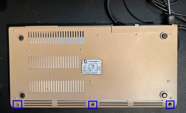
Final result after cleaning and sunbrighting is quite good I think. See picture below.

Keyboard
Keyboards looks to be without any damage but the keys are... really sticky! It is not like that something has been spilt over it, but I think that the combination of some dust and moist have made some kind of sticky goo. All keys are removed with a keycap puller and the keys are placed in some mild soap water for 24 h.
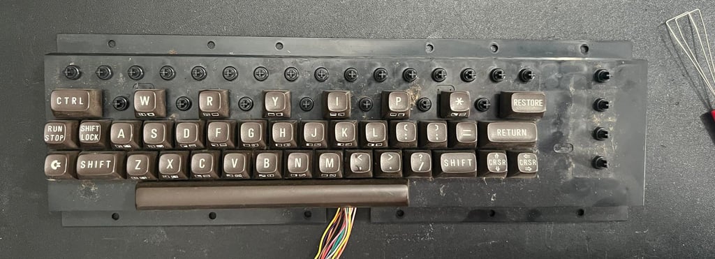
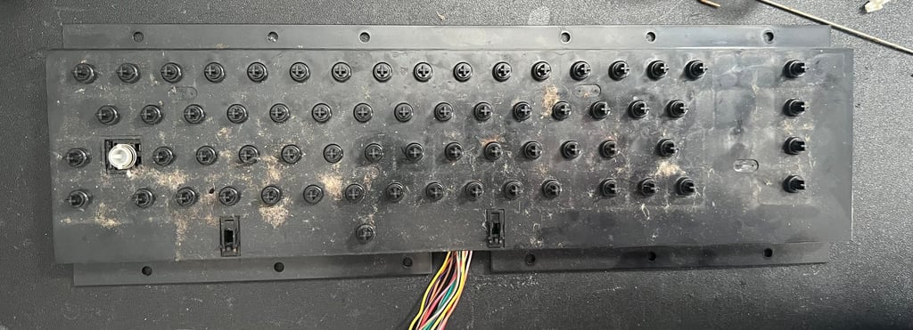
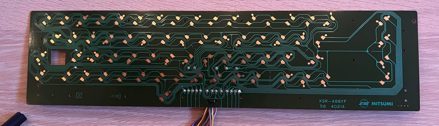
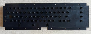
When all the small screws on the backside are removed the whole PCB is lifted out of the plastic casing. The PCB is in good condition - also indicating that the "goo" on the keys have not reached the PCB. Nevertheless, the PCB is cleaned carefully with isopropanol.
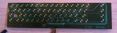
This is a Mitsumi KSR-A66YF PCB which is a very common version. I can not see any damage to either traces or pads - and no sign of corrosion.

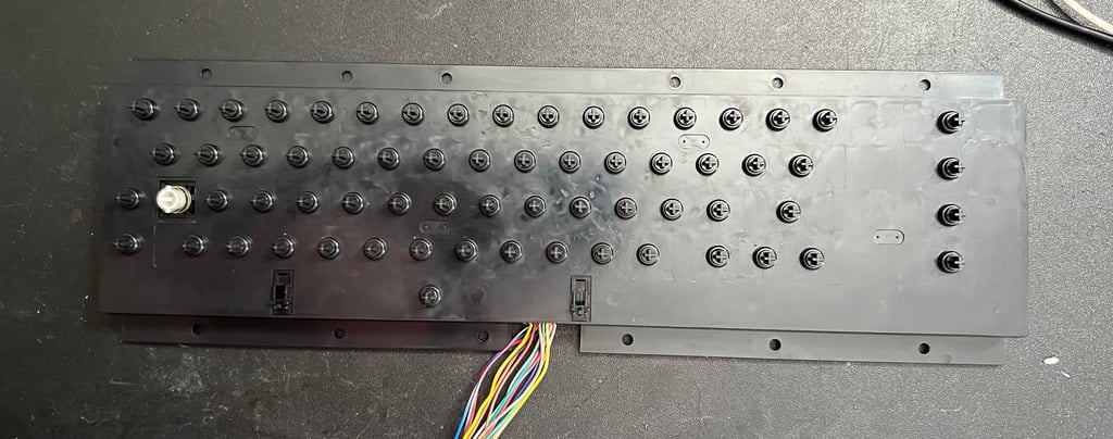
Note that the spring beneath the spacebar is a bit larger than the rest - so it is a good idea to place this spring in a separate bag.
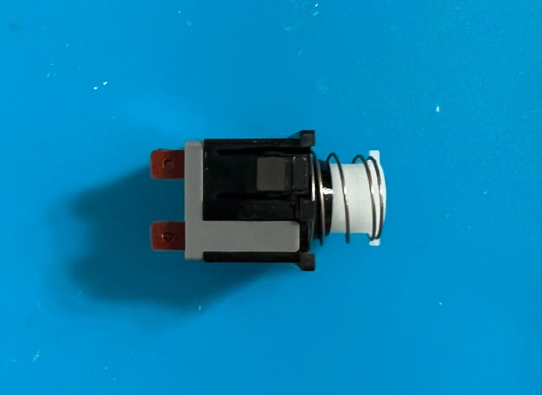
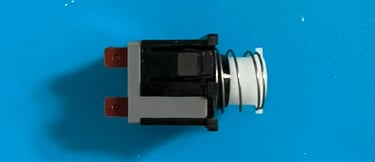
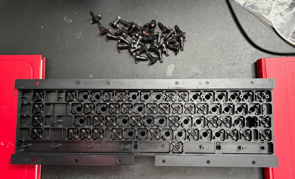
The two wires connecting the SHIFT LOCK are desoldered. Then the SHIFT LOCK is removed by pushing firmly from the backside of the keyboard towards the front.
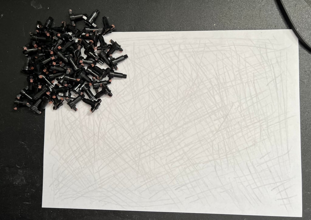
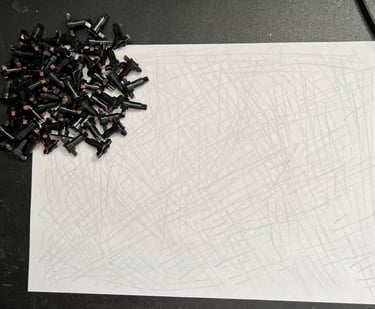
Each of the plungers are carefully wiped on a clean paper. I use this method as I find it the most gentle way to remove the grease and dirt from the carbonized rubber. But if this method doesn´t make the plungers work again I need to use some isopropanol.
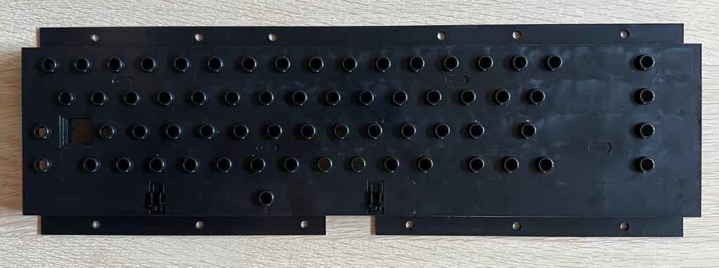
After cleaning the plastic casing with only some luke warm water and mild dishwasher soap it looks good as new.
When everything is cleaned the keyboard is assembled which is a tedious as the disassembly. But the result is very promising.


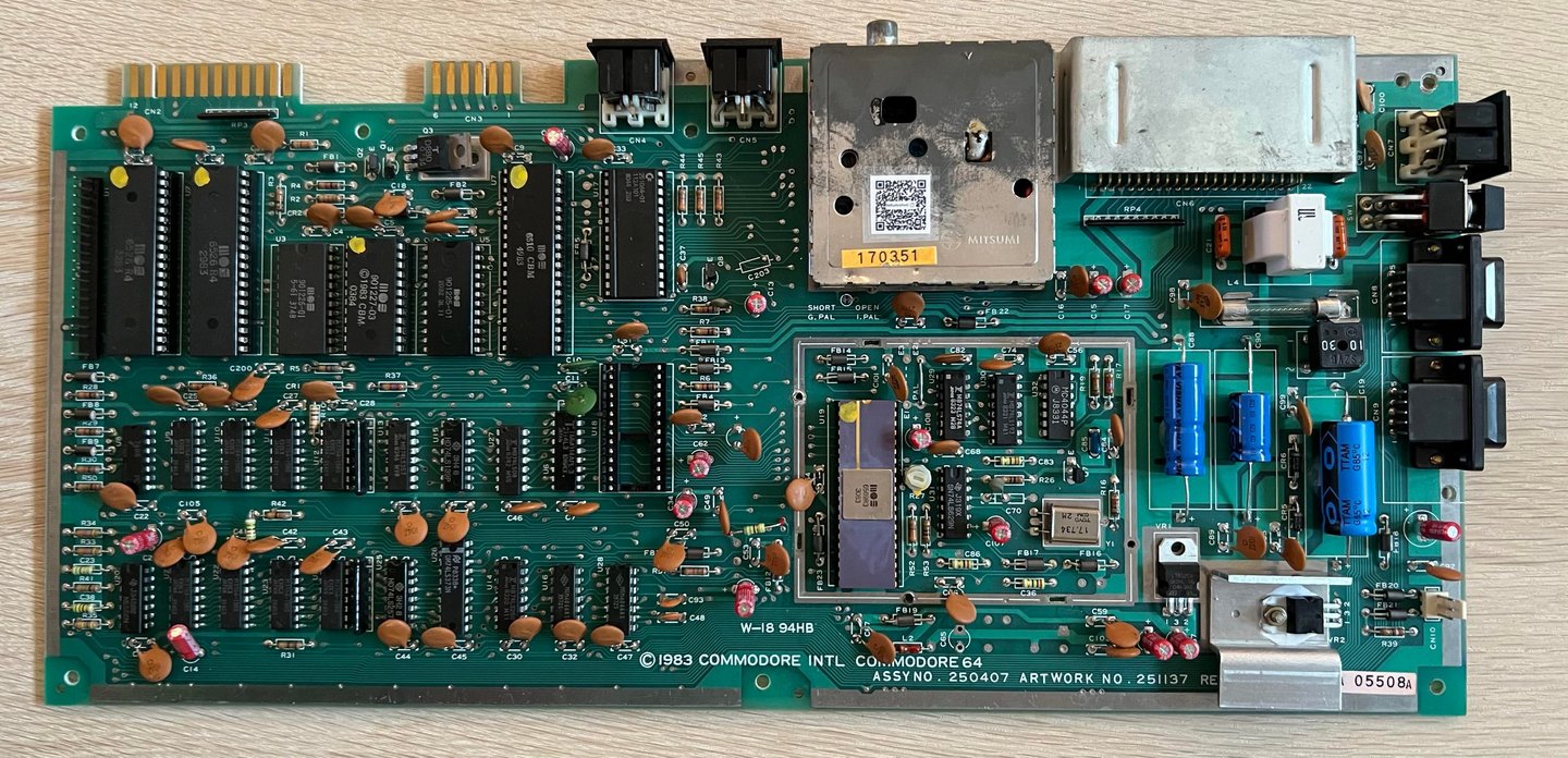
Mainboard
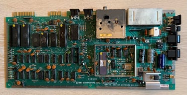
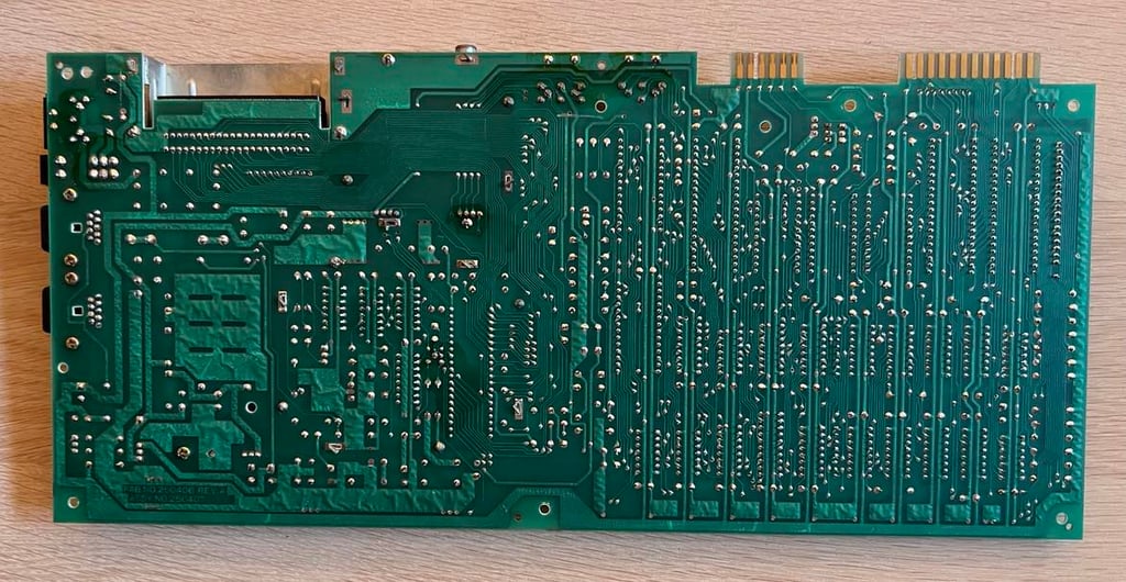
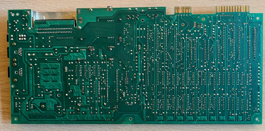
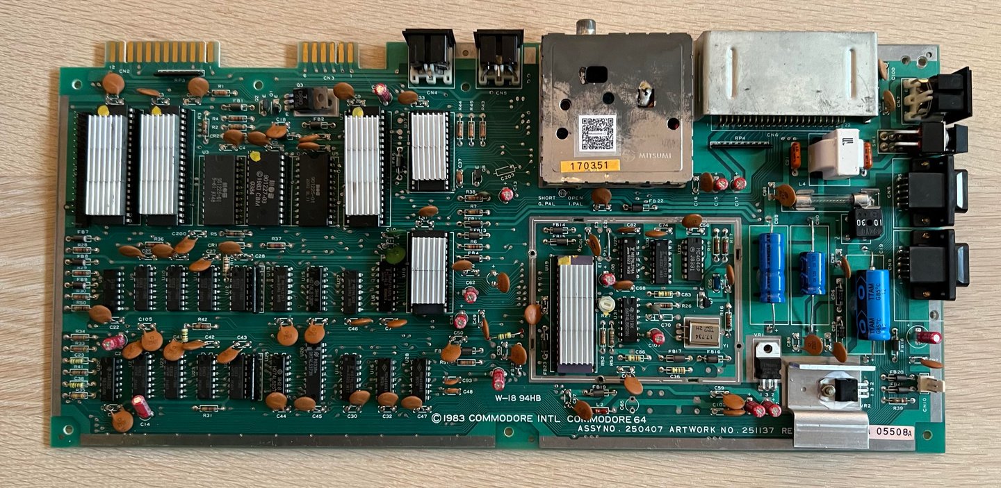
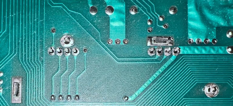
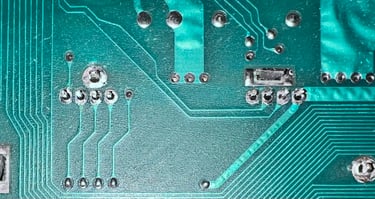
This mainboard is of type "Assy 250407 / Artwork 251137 (Rev B) / W-18 94HB". As previously mentioned it looks to be in good condition. There is quite a lot of dirt and grease on the board, but this is normal. But on the backside I find a lot of sticky stuff. I am not really sure what this is - but I assume this is some kind of flux residue. Below are some pictures of the mainboard before refurbishment.
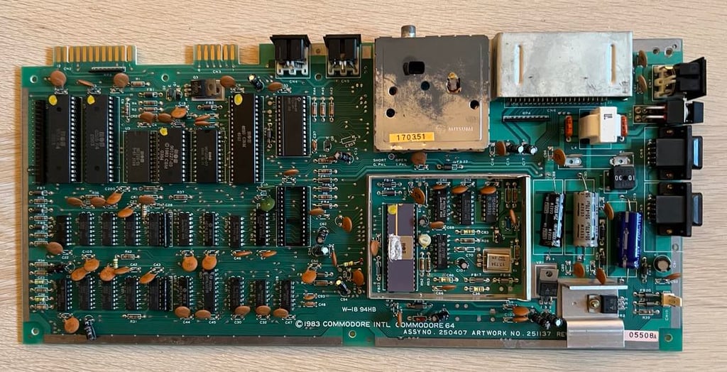

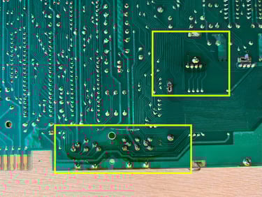
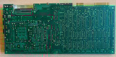
A closer look at the "sticky stuff" (example areas in yellow squares). Probably easy to remove with some isopropanol. These kind of things do not affect the mainboard in any way, but I do like to make sure that the PCB is clean to prevent corrosion.

Before cleaning the whole mainboard with mild soap water and isopropanol the SID and fuse is removed. The SID is not required for starting the Commodore 64 and the fuse can leak so that water could penetrate into the glass cylinder.
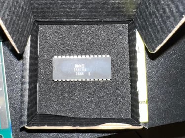
And WHAT A SURPRISE - This is the R4 revision of the MOS6581 SID chip! I did not expect this! To me this looks like a quite old Commodore 64 and this "new" revision of the SID was not installed at factory. Fingers crossed that it works! The R4 revision often go under the name "AR - Acoustic Resonance" and is acclaimed for having the best SID sound.

Visual inspection
The mainboard looks to be in a very good condition. I can not see any sign of rework either (e.g. soldering). The only trace of someone changing anything is that the MOS 6581 SID is from a completely different production year than the rest of the chips. See table below.
After cleaning the mainboard looks very good after cleaning. It required quite a lot of cleaning indeed. Not only soap and water is used, I need to use a substantial amount of isopropanol also to get rid of the grease and dirt. But I am happy with the result - pictures below.
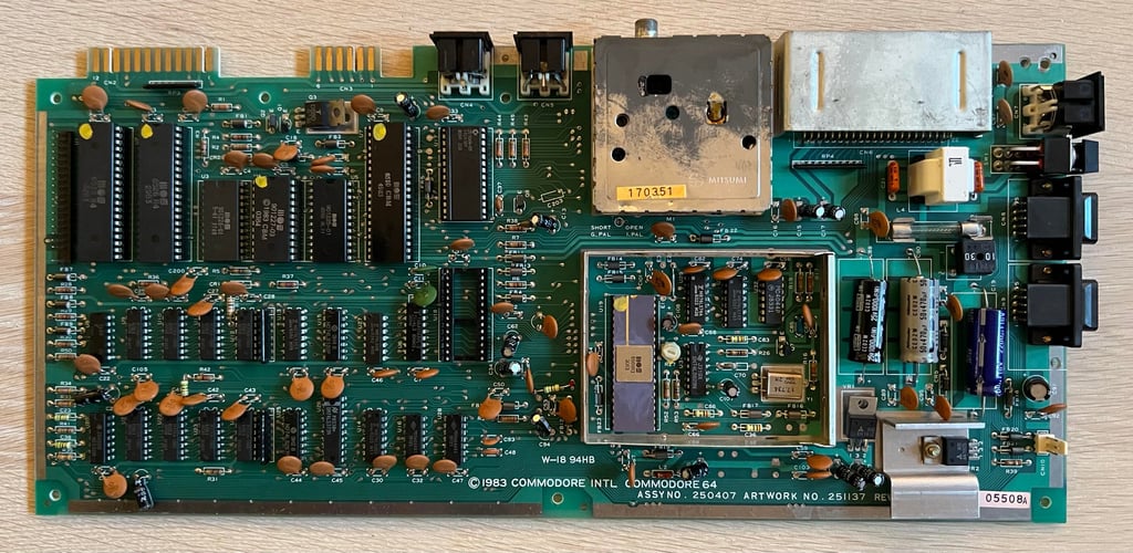

I am glad to see that there are no RAM chips from Micron Technology (MT). These are notorious for failing. Instead, good quality OKI chips are used. Also, the glue logic is also made from good quality vendors such as Hitachi, Fujitsu and Texas Instruments. Sometimes Commodore used their own chips MOS 77xx series which are also notorious for failing.
My guess is that this Commodore 64 was produced in the winter of 1984. As can be seen from the table above the Kernal ROM was manufactured in week 3 of 1984 so I think that a qualified guess that this was the newest chip used in the manufacturing. The SID chip I would guess was installed almost three years later - probably to replace a broken SID. The R4 is normally used in mainboard with assy 250466 and not with this assy - so this was a pleasant surprise (if it works that is...).
Checking the voltages
Before checking that all voltages are within tolerances I check that there are no short circuit before connecting the power supply (PSU). I check this on the user port for both the 9 V (AC) and 5 V (DC) input. No short circuit is detected so I think it should be safe to power on.
When the power is on I measure the main voltages. All voltages are within acceptable values (see table below). Checking the voltages first is a good practice - if you find voltages that are barely within acceptable range this could case the machine to malfunction. Note that the voltages will be measured again when the refurbish is complete to make sure they are still within acceptable tolerances.
Initial test
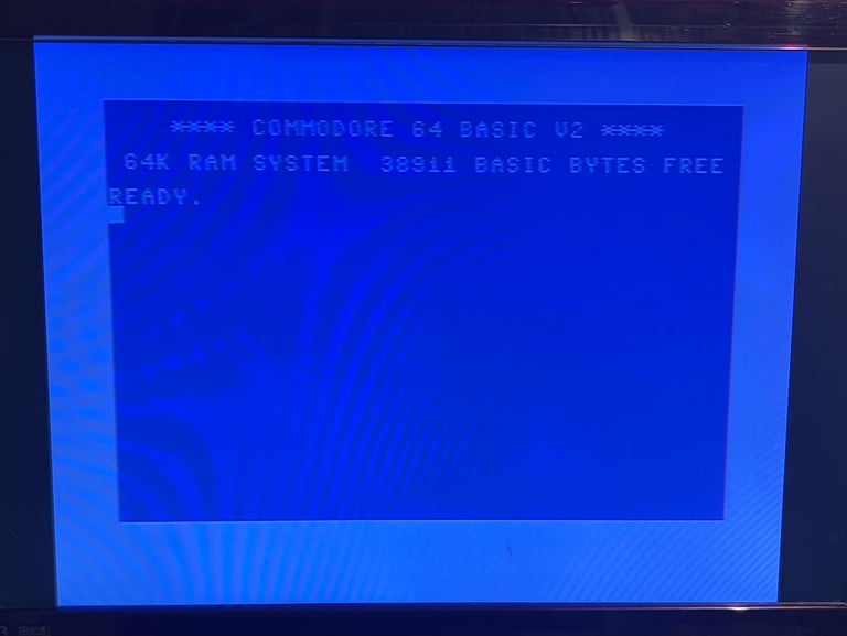
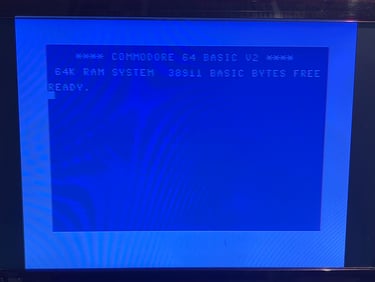
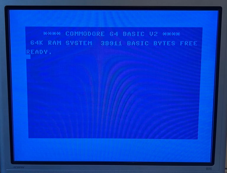
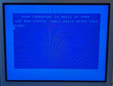
Turning the Commodore 64 show a... <DRUMROLL> BLUE SCREEN </DRUMROLL>. So this is a very good start.
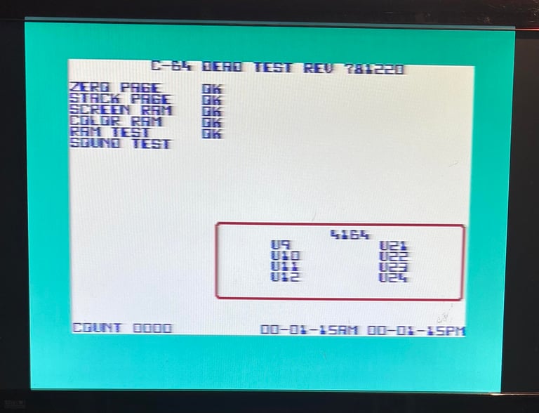
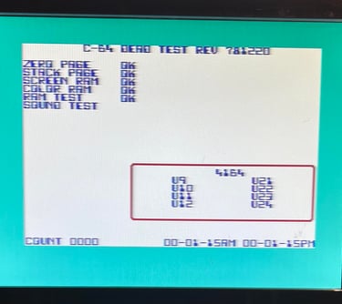
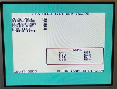
Also a quick check with the dead test cartridge shows that the main chips such as CPU, VIC-II, CIA, RAM and CIA doesn´t show any immediate issues. That said, there still be faults with the machine. But I will check that later with comprehensive testing - and repair anything not working.
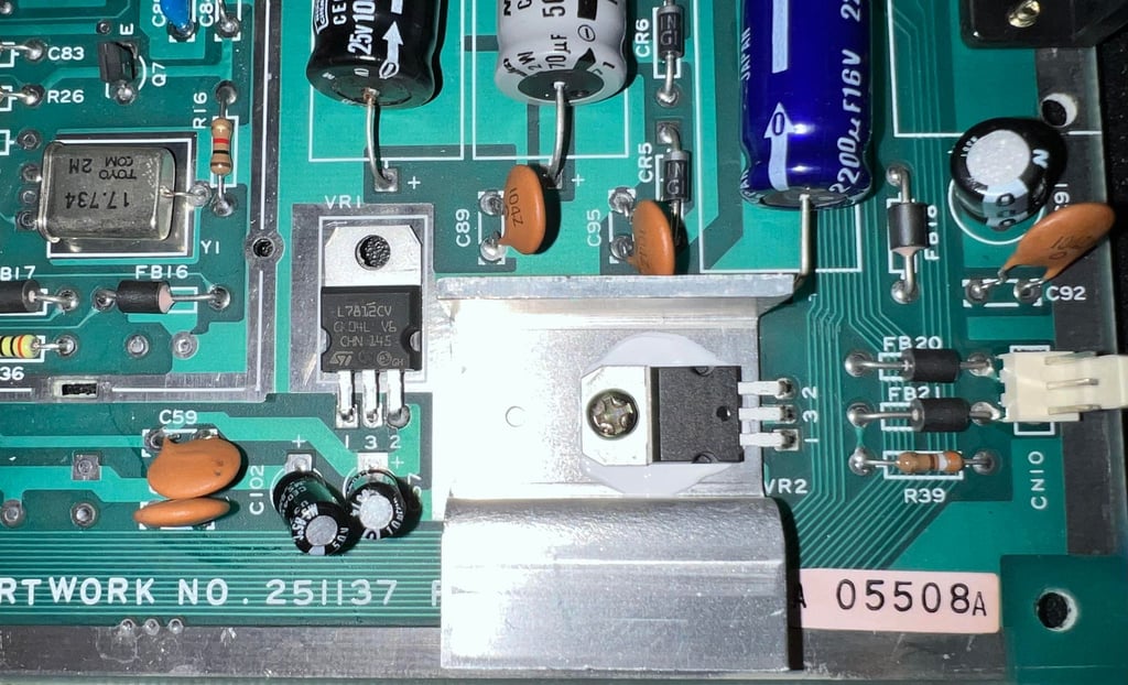
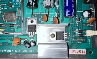
Replacing the voltage regulators
There are two voltage regulators on the mainboard which are good practice to replace; the 12 V DC [7812] and 5 V DC [7805]. These two regulators are used to supply the 6581 SID and 6569 VIC-II chip and since MOS chips are very fragile when it comes to slightly high voltages replacing these regulators can reduce the risk of destroying these valuable chips.
A more detailed article about Commodore 64 voltages can be be found in the HOWTO - Checking the C64 voltages.
Both the 7812 and 7805 voltage regulators are desoldered without any damage to traces or pads.
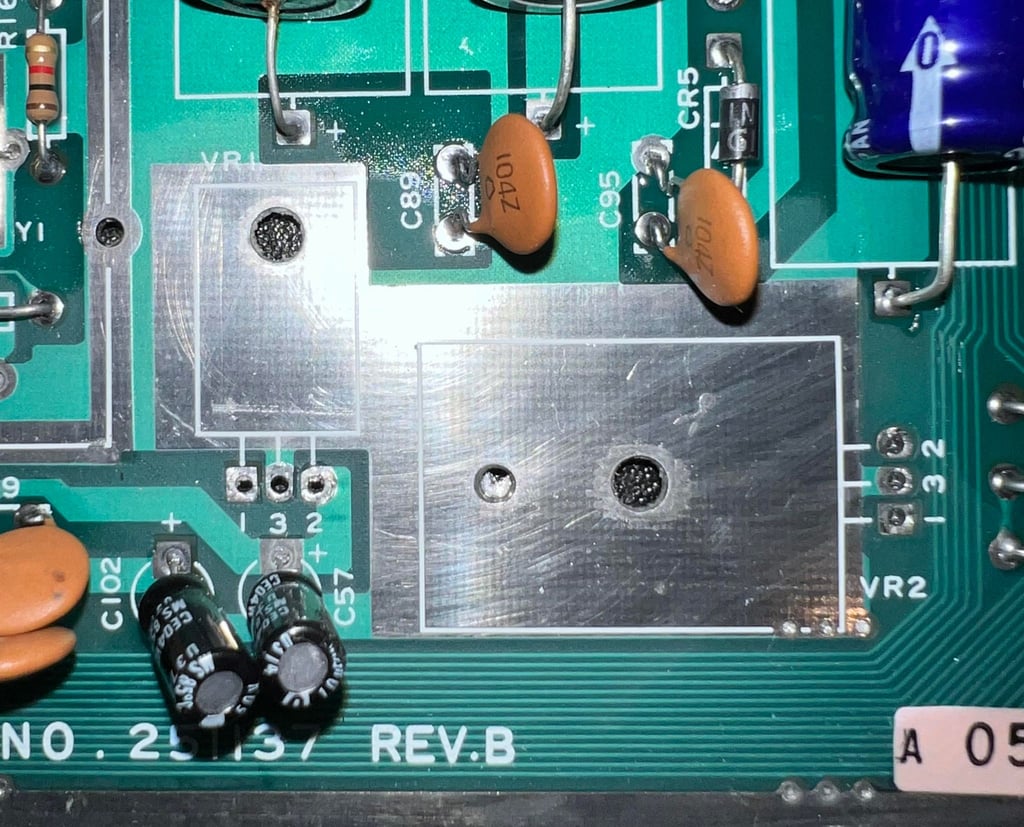
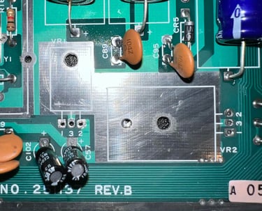
The two new regulators are soldered back onto the mainboard. Note that it is only the 7805 (5 VDC) regulator that is mounted on a heatsink with a screw and nut. This is normal. The 7805 gets really hot. Also, there is some new heat paste between the 7805 and heatsink to make sure the heat is transferred properly.
Replacing the electrolytic capacitors
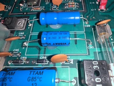
All the 18 electrolytic capacitors are replaced with new quality capacitors from Wurth Electronics and Vishay. A list of all the capacitors can be found here. Note; in this list all the 10 uF are rated for 50 V, but the replacements capacitors are rated for 25 V. There is no technical reason for using 50 V capacitors, this is probably done only because Commodore used "whatever was available" from supply chain.
The 470 uF, 1000 uF and the 2200 uF are glued to the mainboard. This is probably not strictly required for new 2023 capacitors, since the old ones were glued on the mainboard I chose to do the same.


Adding heat sinks to critical chips
Heat is a factor which can reduce the lifespan of important ICs on the Commodore 64. And quite a few of these chips are now rare - which means that replacing these with "new" could be quite expensive. So it is good practice to add heat sinks to the most important chips:
MOS 6510 CPU
MOS 6559 VIC-II
MOS 6581 SID
2 x MOS 6526 CIA
PLA
Picture below shows the mainboard when all the heat sinks are added.

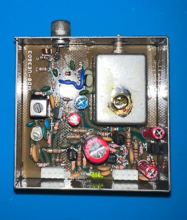
RF-modulator
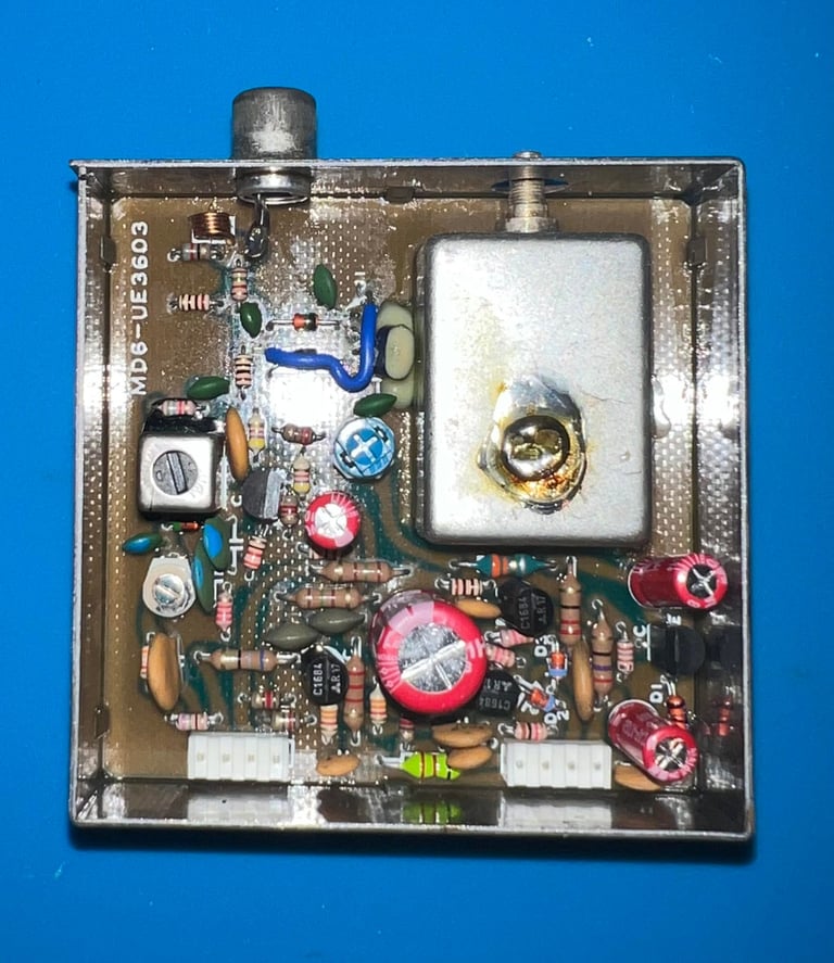
This is a Mitsumi MD6-UE3603 RF-modulator. Checking the capacitor list for this model I see that there are four electrolytic capacitors inside it; 1 x 10 uF [16V], 2 x 100 uF [10V] and 1 x 470 uF [10V]. These four will be replaced with new quality capacitors.
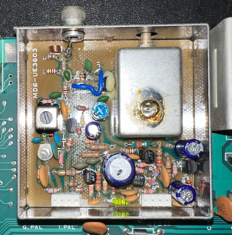
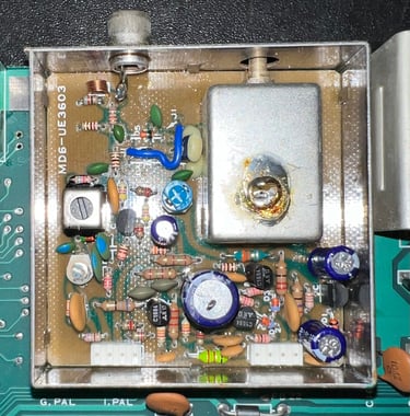
Desoldering the RF-modulator is not trivial. I use a combination of tools to remove it; soldering iron, desoldering gun, hot air, pliers and a thin flat screwdriver. But I manage to desolder it without damaging anything as far as I can see.

The four capacitors are desoldered and four new capacitors are soldered back in.
Testing
Proof is in the pudding - does it work?
Testing is done through two main stages:
Testing the basic functionality and chips
Testing by using the machine playing demos, games etc. accessed by both floppy and datasette to verify correct operation
Basic functionality and chips
First test is done using the Dead Test Cartridge. This test doesn´t test all the functionality of the Commodore 64, but it does test the basic functionality of the major chips such as the CIA #1/2, CPU, VIC-II, PLA, RAM and SID. As the picture shows below the test is passed.

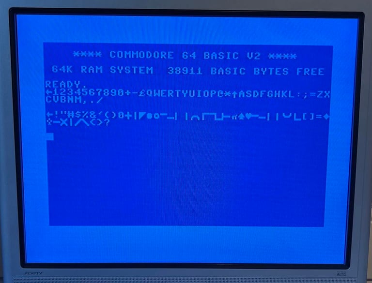
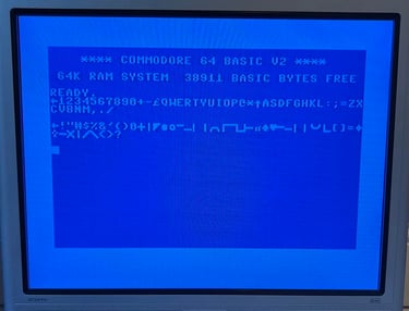
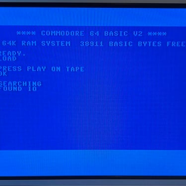
Next test is to power the Commodore 64 to the blue boot up screen and also check the keyboard to make sure all keys works as they should. The test is passed; all keys works and 38911 BASIC Bytes Free.
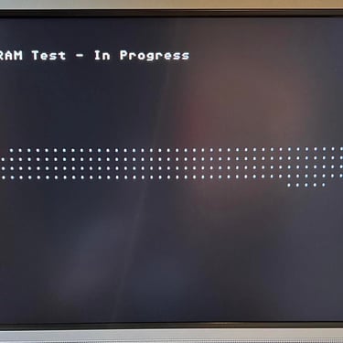
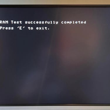
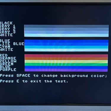
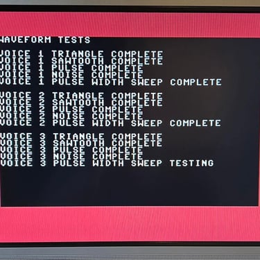
The basic functions of the VIC-II, SID and RAM is tested with 64 Doctor. Note that this is to be considered as basic functionality - more advanced (?) functionality such as sprite handling / collision detection / advanced audio will be tested later. But the basic tests pass without any detected faults (click to enlarge).
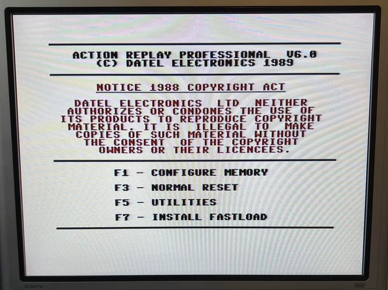
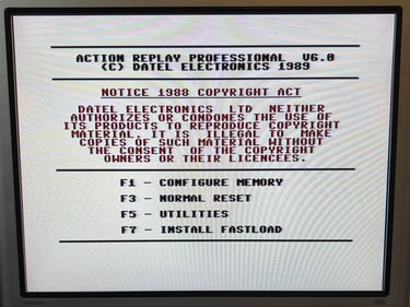
Last basic check before moving to more extensive testing is checking the cartridge. This is done by using the Action Replay VI. Result is that the test is passed.
Extended testing
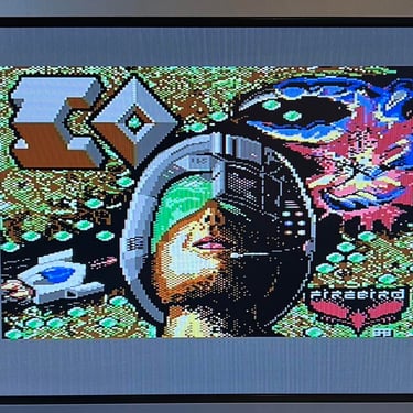
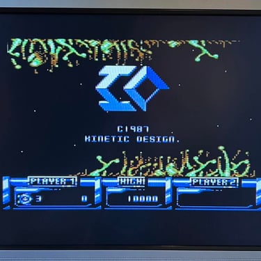
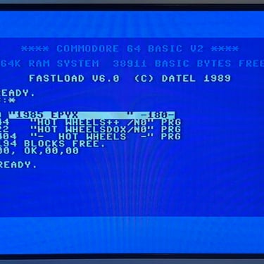
Knowing that the basic functionality of the machine works I continue the testing by using the Commodore 64 for normal operations; playing some games, watching demos, loading from datasette and floppy and using a cartridge. I can not find any issues with this machine. I also pay special attention to the video to make sure that there are no glitches in the graphics - I can´t see any abnormalities. Below is a gallery with pictures from the testing.

Final result
"A picture worth a thousand words"
Below is a collection of the final result from the refurbishment of this C64. Hope you like it! Click to enlarge!


Banner picture credits: Evan-Amos