

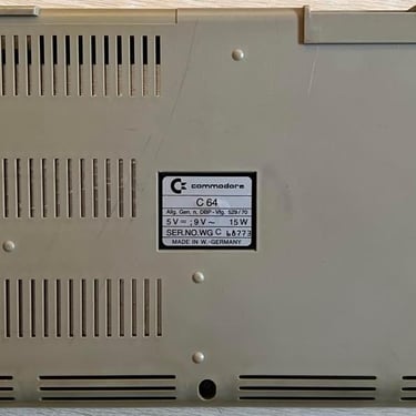
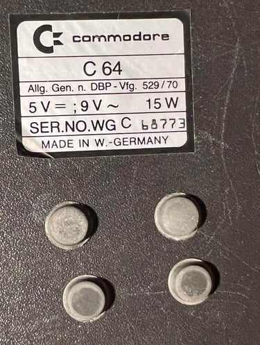
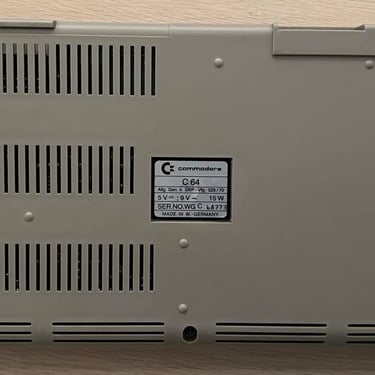
C64 Breadbin
Ser. No. 68773
Assy 250407
Artwork 211137 (REV B)
To refurbish this C64 breadbin the plan is to do this trough the following steps (some of them in parallell):
- Clean and restore the keyboard
- Clean and remove stains from the chassis
- Refurbish main board (cleaning, checking, repairing, replacing capacitors and voltage regulators etc.)
- Recap RF-modulator
- Verify operation by testing
Refurbishment plan
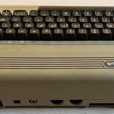
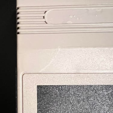
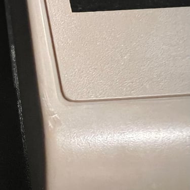
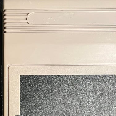
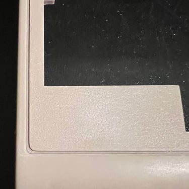
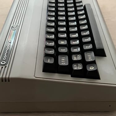
Below you will find some pictures before the execution of the refurbishment plan. It´s very dirty, but looks intact as far as I can see. There is installed a button on the left side on the back of the C64. This is probably a reset button which was quite common to make yourself back in the days.
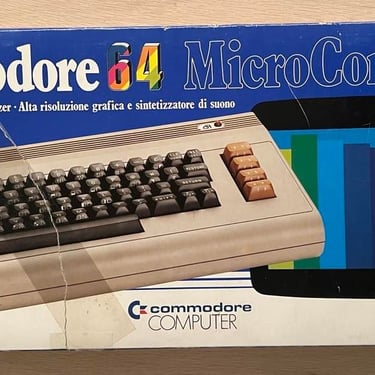
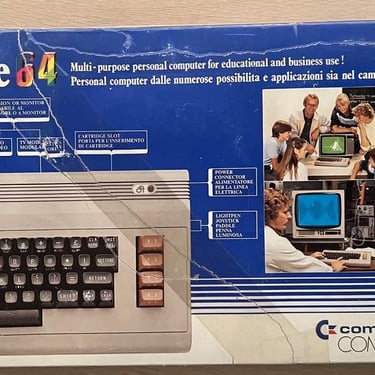
This C64 comes with the original box also. The box have some tear and wear, but looks quite ok. Previous owner have also used tape to repair the box. See picture gallery below (click to enlarge).
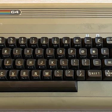
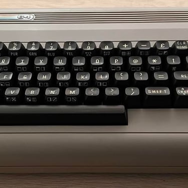
Keyboard
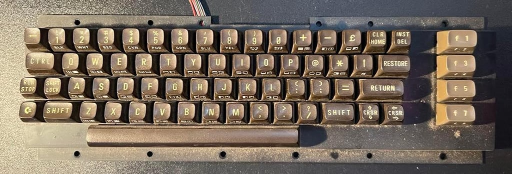
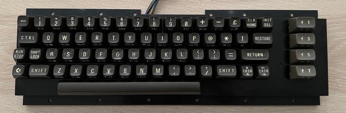
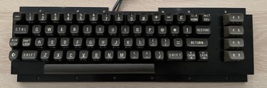
Very glad to see that the keyboard looks in good condition. Yes, it´s very dirty but otherwise looks ok:
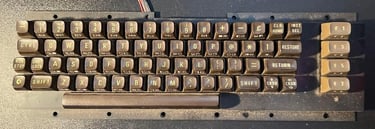
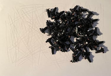
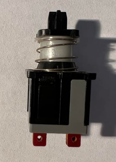
All keys are removed using my key puller (or hands). I would not recommend using screwdrivers to pull them out. I´ve done that myself quite a few times (thinking that it will speed things up), but there is a high risk that you will break some of the plungers. So put on some nice music and take the time it requires to get all the keys off the plungers in a gentle way... A little note: the spring for the spacebar is different than the rest!
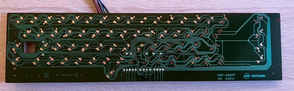
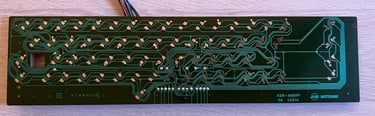
The keys are placed in a box filled with luke warm soap water, and left here for a couple of hours. Meanwhile the keyboard is completely disassembled unscrewing a million screws and desoldering the shift lock key wires.
I use isopropanol to clean the keyboard PCB. And as far as I can see there are no corrosion at the board - it looks mint after cleaning. See picture below.
To clean the plastic chassis holding all the key plungers and springs I use only water and mild soap. It´s VERY dirty, but it´s easy to clean. The result is very nice:

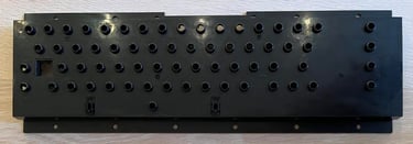
Refurbishing the plungers I use a little trick. I know that other people do this in other ways, but I find this method quite effective and giving good results. I carefully slide each of the plungers over a paper. This will remove most of the crust and dust that are stuck on the little rubber pads - and don´t risk damaging these with chemicals. The shift lock button is cleaned only with a microfiber cloth.

Cleaning the keycaps is really hard! Even after a couple of hours in mild soap water they are still dirty. So I clean each key individually with glass cleaning spray, and then leave them in soapy water for a while. The keys are also slightly yellowed so the keys are put in a small plastic bag filled with 12 % hydrogenperoxide (cream) and exposed to UV light. They are not returned completely to the original white color, but I think the result show improvements.
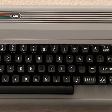
Below you see the keyboard with all the parts properly cleaned, retrobrighted and re-assembled (click to enlarge).
Chassis
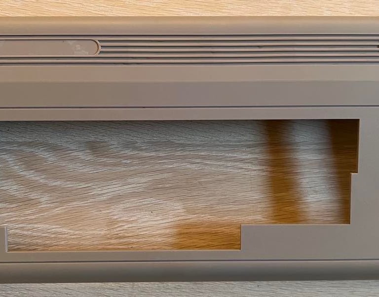
The chassis is disassembled by removed the three screws at the bottom, and removing the nut which holds the reset (?) button in place. I also remove the little plastic ring holding the LED from the inside of the chassis. And what a nice surprise: all of the three plastic brackets at the rear side of the top cover are intact! That´s not so often I see - these tends to get very brittle and break due to old age.
This chassis needs a very good cleaning. So I decide to remove both the Commodore- and Power badge from the top cover. And from the bottom cover I remove all four rubber feets and the serial sticker. To remove all of these I apply some heat from a hair dryer and very carefully lift them with a sharp knife and a small (thin) screwdriver.


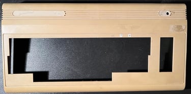
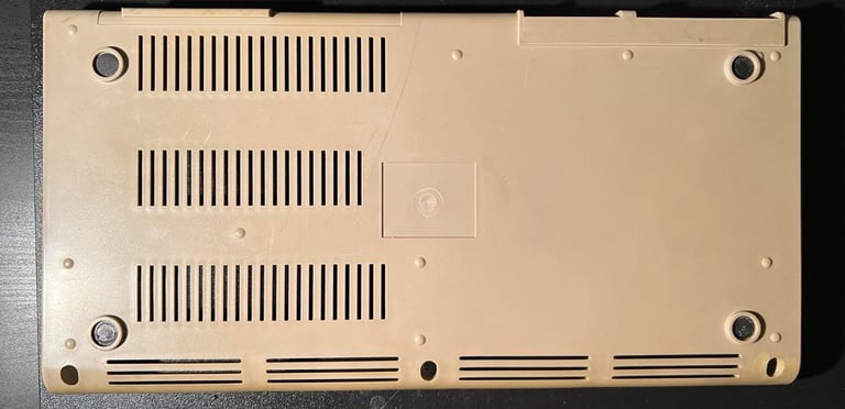
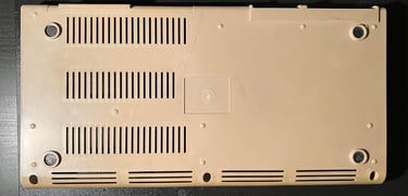
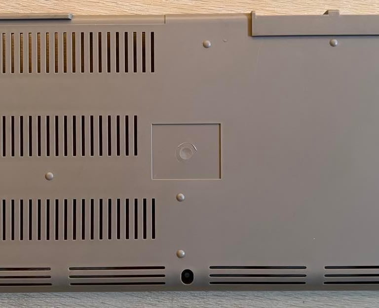
Now, with the chassis completely disassembled and all stickers out of the way it´s time for some serious cleaning! Below you will find the pictures of the top- and bottom cover before the cleaning process begin. Click to enlarge.

The chassis is placed in a sink filled with luke warm mild soap water for a couple of hours. This will probably not remove all of the 40 year old dirt, but it will get some of the grease to disappear. To clean it further I will use a combination of glass cleaning spray, baking soda and isopropanol. And maybe a touch of spray for oven cleaning if something is really hard to remove - but this spray is corrosive to plastic so I need to be careful.
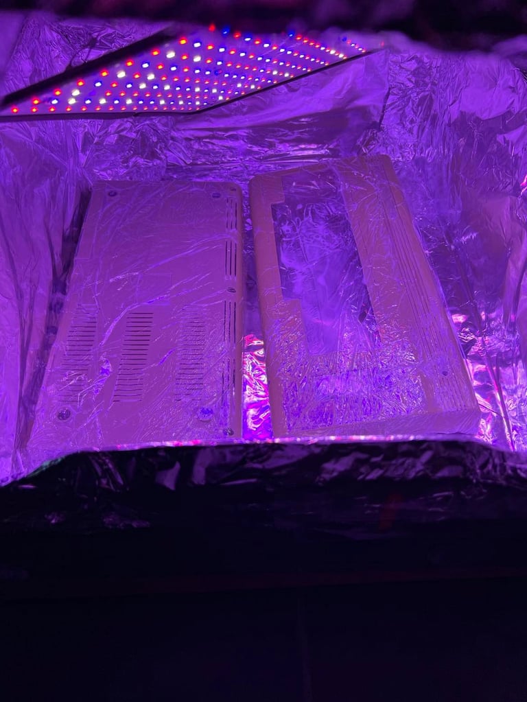
After cleaning the chassis looks way better, but still it need some retrobright to get it back to a nice condition. I use 12 % hydroperoxide cream and UV-light to retrobright. This takes about 8 hours to complete. But I think the result of this is quite nice! See pictures below - click to enlarge.
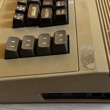
Now, I notice that there is a mark (from a wrapped cable?) on the left side below the badge area. I don´t think this matter much, and it´s not that visible as the picture is. But I try to remove the most visible parts with some wet P1000 sanding paper. And I think the result is quite ok! See below for "before" and "after" pictures.

Main board
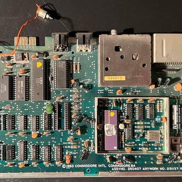
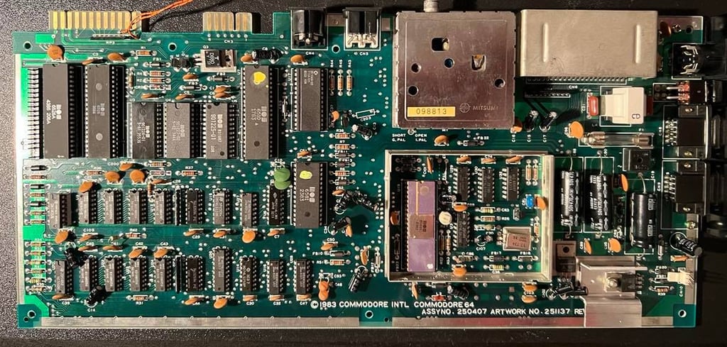
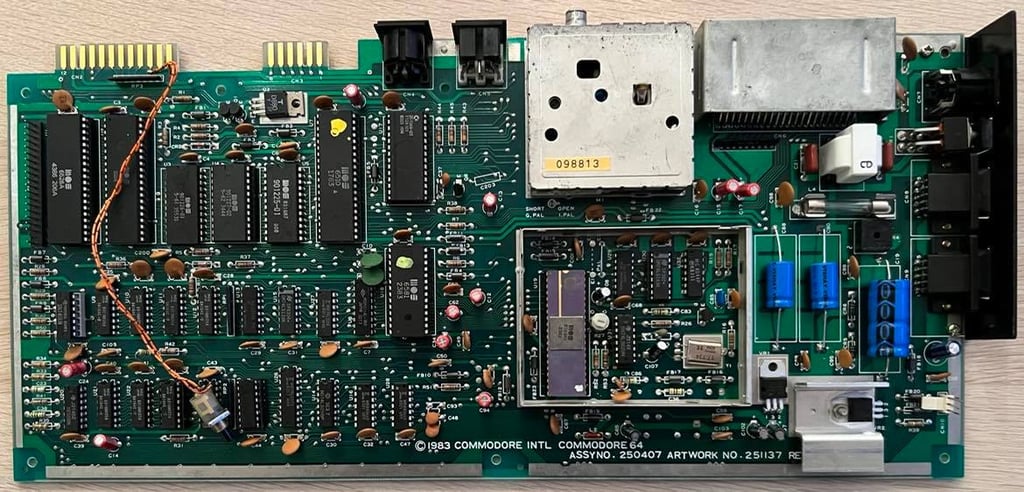
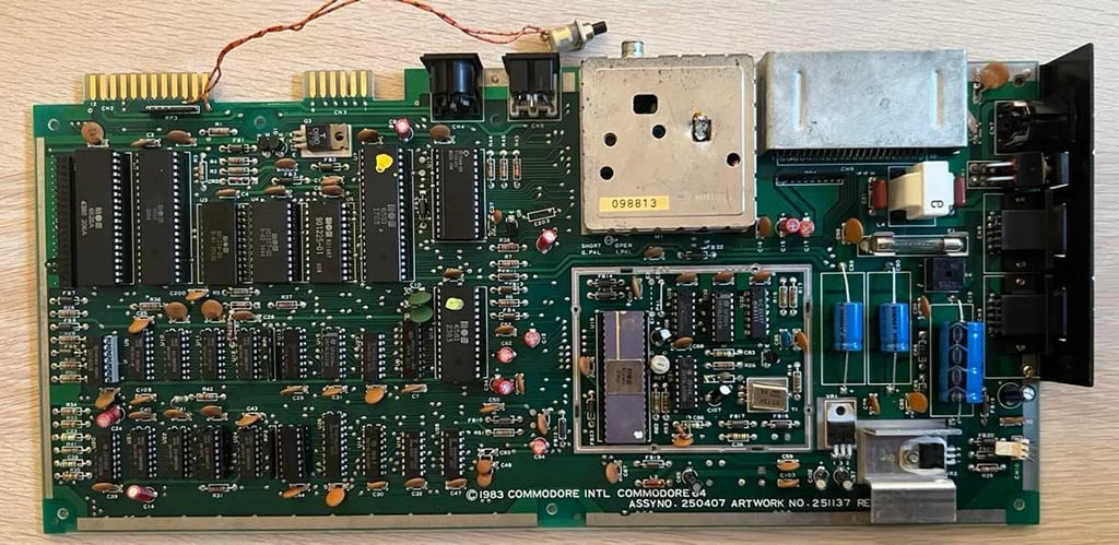
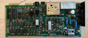
This is the assy 250407 Rev B model of Commodores main boards. If you are interested you can find more details about this board at Retro Rewind and at Breadbox64.
Before powering up the main board I do some visual inspection, and I notice a few things:
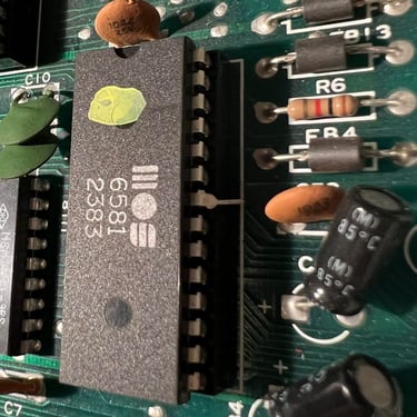
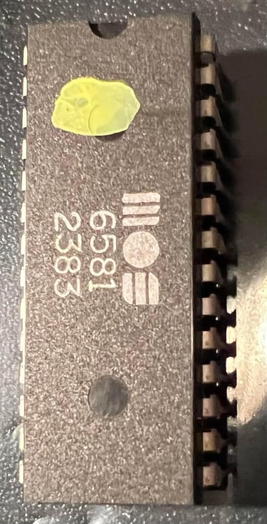
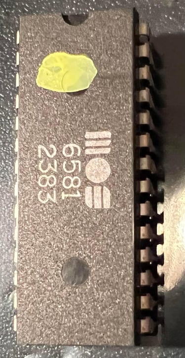
One of the pins of the SID chip is not in the socket (!) What?!
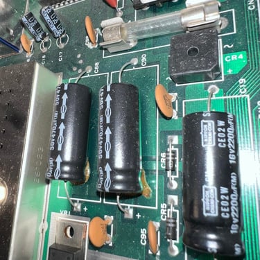
Three of the large capacitors are leaking. This is quite common so no surprise there.
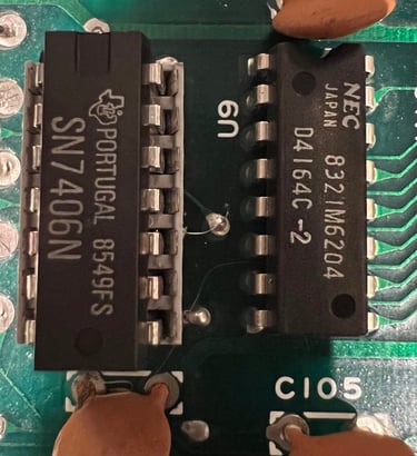
The 7406 logic chip is in a socket. My guess is that there used to be a MOS 7707 here which failed and was replaced with a TTL 7406 chip.
The SID and VIC-II are socketed. That´s normal, but also the PLA, CPU, Kernal ROM and both of the CIA chips are in socket. I can´t guarantee it, but my guess is that some of these have failed previously and were placed in sockets during repair.
Most of the chips are from 1983, but I notice that the CIA #1 is from week 43 in 1986 and the CIA#2 is from week 38 in 1984.
The reset switch is connected somewhere around the user port pins
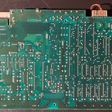
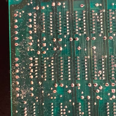
The PCB looks ok. Some flux residue and dust, but otherwise it looks ok.
Below you will find some pictures detailing some of the points above.
One last thing I also check before powering up the main board is to check for major short cuts that could ruin the power supply. I make sure that there are no short cuts between:
Voltage out and ground from the 7805 regulator
Voltage out and ground from the 7812 regulator
5V DC and ground on the user port
9V AC and ground on the user port
Everything looks to be ok here, so it´s time to start up to see what we get... I remove the SID chip before power up since this was misplaced in the socket and also since it is not required for the Commodore 64 to start.
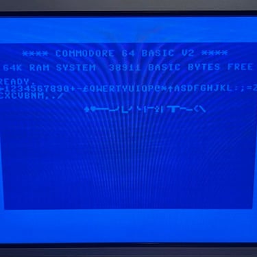
And, lo and behold, it WORKS! Well, at least it boots to the default Commodore blue screen with 38911 KB free RAM. Nevertheless, it still doesn´t mean that everything works (e.g. the SID) but it´s a fantastic start.
Next step is to give the main board a proper washing. I wash the whole PCB with plenty of water and some mild soap, and clean it with a soft paint brush. It may sound crazy to wash the whole main board in water, but all the components are water proof (except the fuse which I remove first). But a smart trick is to spray it with plenty of isopropanol and let it dry for at least 24h.
While it´s drying I fix the pins on the SID chip with some pliers. The result is promising:
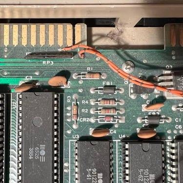
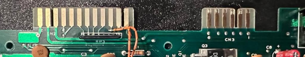
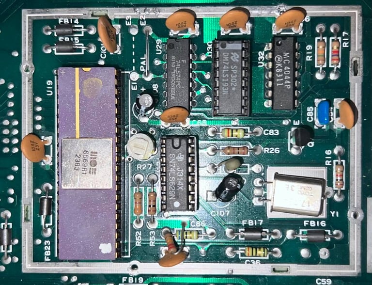
After the main board is cleaned I notice something important. Remember that I said the 7406 was in a socket? I now see that there is a bodge wire connected to a solder point on the board (see picture - and click to enlarge). I guess that a trace was lifted in the desoldering process when it was repaired. Unfortunately, lifting a trace happens from time to time. But it can be repaired which is what we probably see here. I will not try to desolder this socket to see what´s done. I think it´s better to leave it this way to not destroy any more traces. The repair that is already done should work fine.

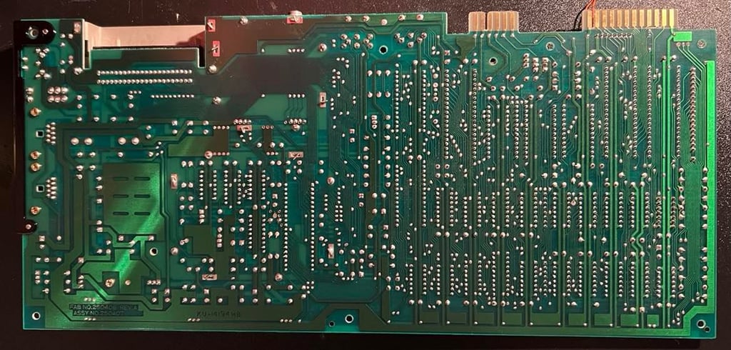
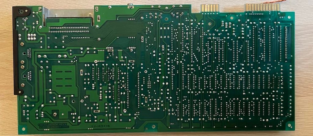
Below are some pictures of the cleaned main board (back and front). The SID chip is also in place again.
Even if I know that the Commodore 64 boots ok, I always measure the voltages. I do this both before and after I replace the electrolytic capacitors and voltage regulators. It´s important that the voltages are correct for the C64 to operate as expected. There are four voltages I measure:
5 V DC (CAN): This is a special 5 V made by the 7085 voltage regulator just for the VIC-II chip. It´s therefore not the same as the 5 V from the power supply (PSU)
12 V DC: Made for the SID and VIC-II chip
9 V AC: From the PSU - Used for peripherals at the user port
5 V DC: From the PSU - Used to power all the chips except the VIC-II


Before continuing with replacing the old electrolytic capacitors I use this main board to help another main board! In parallell while refurbishing this C64 I also refurbish another C64 breadbin with serial 606581 which does not have a working main board. These two boards are more or less identical: both assy 250407, both artwork 251137 and only differ between REV B and REV 6.
I use this working C64 for two reasons:
Reference for signals while probing with the oscilloscope on the non-working C64
Verification of working chips with the samme assy
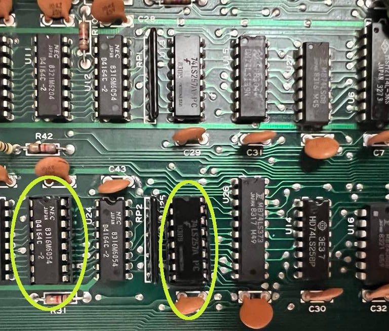
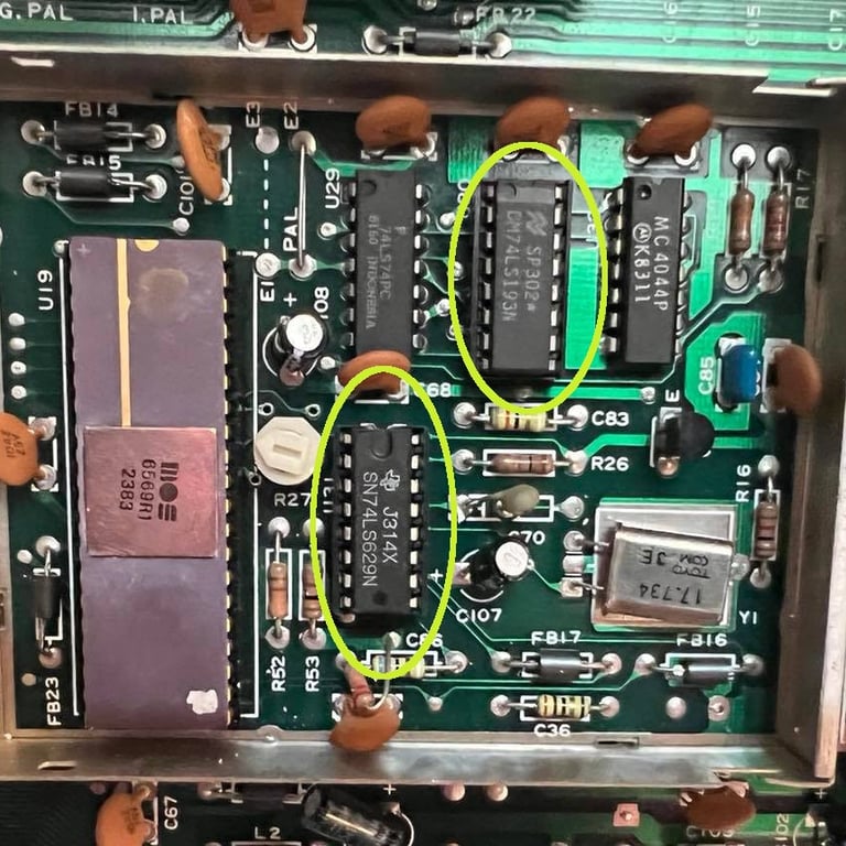
As a consequence of this the following chips are desoldered and placed in sockets (see pictures below):
1 x 74LS257
1 x 74LS139 (in VIC area)
1 x 74LS629 (in VIC area)
1 x NEC Ram chip
It´s always nice to have chips in sockets anyway so to help "a friend C64" was worth it! But now back to recapping the main board!
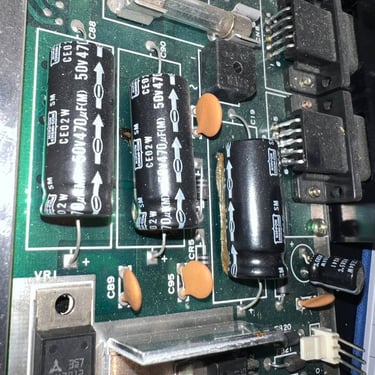
All of the electrolytic capacitors are replaced on the main board. The reason why I change these is that these capacitors will dry out due to old age or leak (as three of the large capacitors on this board have). I use quality capacitors from Kemet, Wurth Electronics and Panasonic/Vishay bought from no.mouser.com and www.retroleum.co.uk.
The following capacitors are changed:
1 x 2200 uF [16V]
1 x 1000 uF [25V]
2 x 470 uF [25V]
1 x 100 uF [16V]
16 x 10 uF [25V]
Note that I´ve used 25 V ratings on the 470 uF capacitors. These were originally rated for 50 V, but I don´t really think this is required. It´s good practice to always replace the caps with either the same or higher voltage rating - but 50 V is probably used only because this was what Commodore had in stock at production time. As far as I know there will be never above 25 V on the main board. Picture below of the main board with all the new capacitors in place.
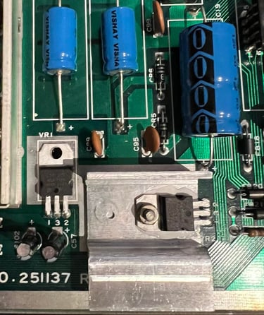
After the electrolytic capacitors on the main board have been replaced, I replace both the 5 V and the 12 V voltage regulators. Why? Well, for the C64 both to work properly and not being damaged the voltages needs to be within a certain range. Too low and the chips will not work, and too high they will be destroyed. The old voltage regulators are almost 40 years old. These two voltage regulators are only used to supply power to the SID- and VIC chip (the others get their 5 V from the PSU). Nevertheless, the SID and the VIC a precious chips so we should try our best to take good care of them - also by making sure power supply is good and within correct voltage range. Picture below show the new voltage regulators installed.

The user- and the datasette port is also cleaned with a rubber eraser. It´s essential to have good connectivity on these - otherwise you can experience difficulties with loading and such. To make sure that there are no residue from the rubber eraser the ports are cleaned with isopropanol afterwards. They are now shiny and nice!

As a finishing touch the whole main board (back and front) are cleaned with isopropanol. And also the four voltages measured earlier are checked and the table updated (in the "After" column). See pictures below for the final cleaning results. Click to enlarge.

RF modulator
When replacing the electrolytic capacitors in the RF-modulator make sure that you are NOT in a hurry. Well, the thing is that to replace the capacitors are easy-peasy, but to get the RF-modulator module off the main board is not trivial. I will recommend both a soldering iron, desoldering gun and hot air to be used in the operation. The reason for being so careful with this is to make sure you don´t rip pads and traces on either the main board or the PCB inside the RF-modulator can. There are eight pins connecting the main board to the RF-modulator PCB (four for input and four for output).
The way I remove the RF-modulator can on this C64 is is:
Bend all the metal "clamps" so that they are in parallell with the hole on the main board
With both the soldering iron AND the desoldering gun I heat up the solder on the four major pins that fixes the can to the main board. When the solder is completely meltet I enable the desoldering gun. This operation often needs to be repeated a few times - adding fresh solder each time
With the smallest tip I have on my desoldering gun I remove the solder on the eight pins on RF-modulator
I remove the shield around the VIC chip. Why? Well, I don´t need this any more since I will use heat sinks and it enables me to get a better grip when removing the RF-modulator can (see picture below).

With the VIC shield out of the way, I gently try to pry the can off the main board while using hot air around ALL the soldering joints. This operation takes a while and it´s very important to not rush this. The RF-modulator can will come off eventually - just be patient - and use the soldering- and desoldering gun in combination with the hot air gun.
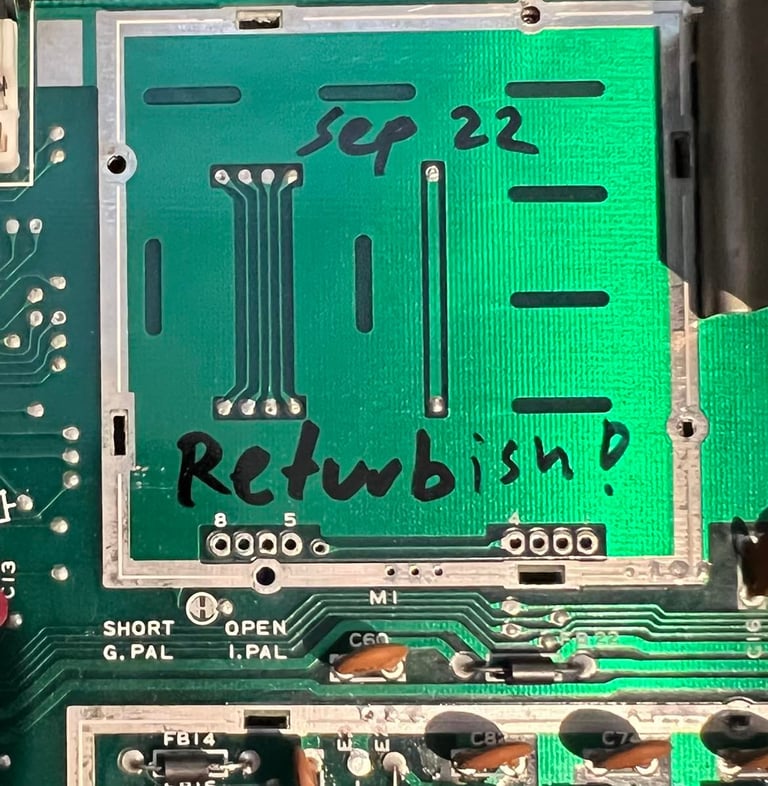
No pads or traces are lifted in the operation. The area is cleaned with isopropanol and just for fun I write "Sep 22 - Refurbish!". This will be under the RF-modulator anyway and not visible :-)! See picture below.

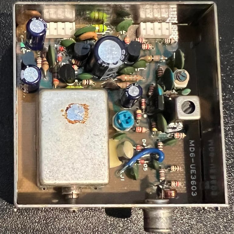
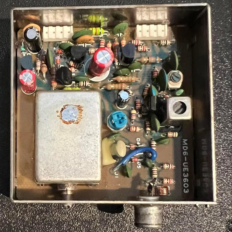
There are four electrolytic capacitors which are replaced:
1 x 470 uF
2 x 100 uF
1 x 10 uF
All capacitors are replaced with quality brands with same (or slightly higher) voltage ratings. See picture galley below for "before" (left) and "after" (right) pictures.
Heat sinks
Do you really need heat sinks on a C64? Well, I think that nobody really knows. But I think there is a positive effect in regards of decreasing the probability that chips will fail. My hypothesis on this subject is that heat is primarily transferred from the chip dye to the surrounds trough the pins. The pins are soldered / socketed and heat will then be divided and transferred both on the front and back of the PCB. Secondarily heat is transferred from the top of the chip package and to the surroundings. The Commodore64 used to have RF-shields (in metal or cardboard) which would trap the heat even more. As a measure to reduce this trapping Commodore added heat paste which touched the metal shield, and also perforated the cardboard to let heat escape.
So my take on this is that I both remove the RF-shield (if possible) and add heat sinks to let the heat flow faster to the surroundings. That means that the temperature will probably be quite the same (with heat sinks or not), but the speed for heating up would be slower and cooling will be faster with heat sinks attached (my hypothesis).

Testing
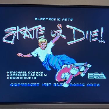
This can be the best - or worse - part of the refurbishing process. It´s the best if everything works perfectly and I can just enjoy great games with magnificent graphics and music. And it can be a real frustration if suddenly doesn´t work...
For this refurbishment it´s just a real joy. As far as I can see and test everything works as it should. I do the testing in two parts:
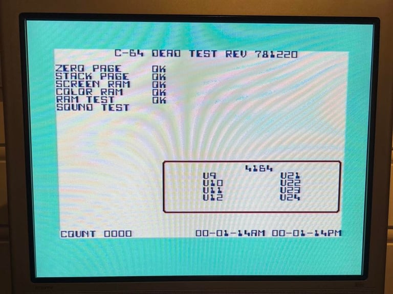
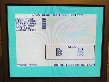
Basic testing with Dead Test cartridge
Comprehensive testing to verify operation from datasette/floppy, music/audio, graphics and joystick, keyboard.
Even if the Dead Test is a very simple test it´s an important one. I checks the RAM (including color RAM), the CIA, the VIC and the SID. So a successful run with the dead test indicates that we´re ready for the more comprehensive testing. As seen from the picture below the dead test show that basic functionality is ok.
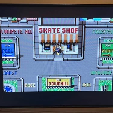
The next part (and the really fun one) is to test that the C64 works as expected:
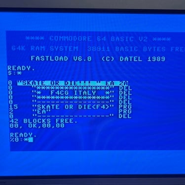
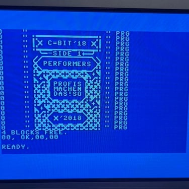
Checking that it can load from datasette
Checking that it can load from floppy
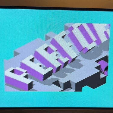
Checking that the SID playback is ok
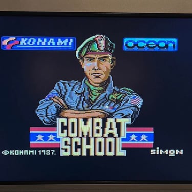
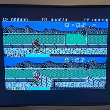
Checking that graphics from the VIC-II chip is ok
Checking that the cartridge works
Checking that all the keys works flawlessly
The result of these tests are that everything is ok as far as I can tell - to me this Commodore 64 works fine! Below is some pictures from the testing - click to enlarge.
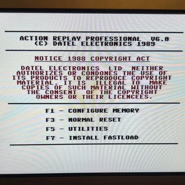
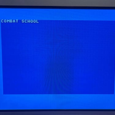

The reset button on the back also works, but there is one thing to notice: if I have a cartridge installed (e.g. Action Replay) and push this custom reset button, the C64 resets fine, but it reset to the C64 blue screen. And to me that´s just fine. If I use an Action Replay (or other freezer cartridge) I would use the reset button on the cartridge and not the one on the back of the C64.
Final result
"A picture worth a thousand words"
Below is a collection of the final result from the refurbishment of this C64. Hope you like it! Click to enlarge!
Banner picture credits: Evan-Amos