

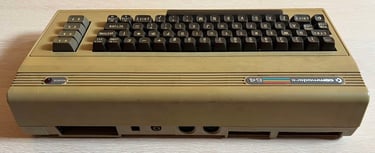
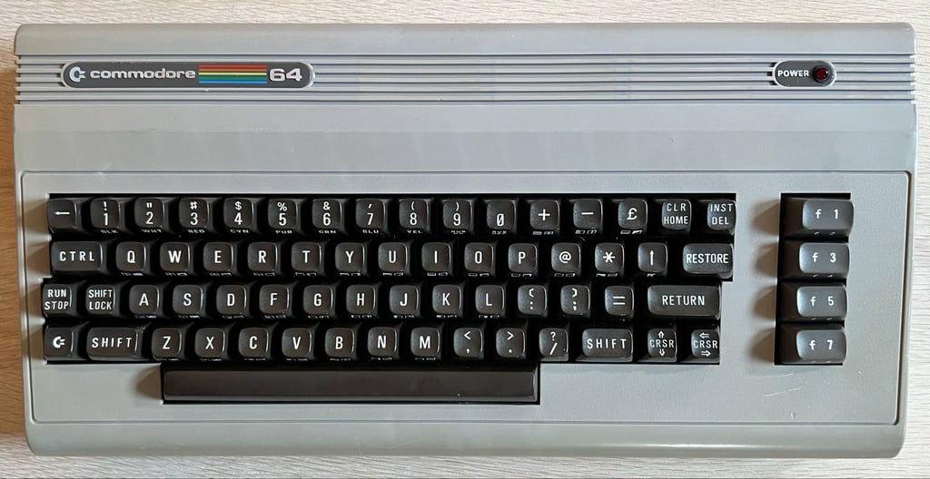
C64 Breadbin [PAL]
Ser. No. 70078
Assy 250407
Artwork 251137 (REV B)
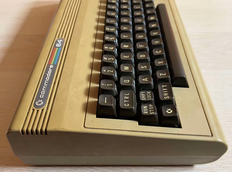
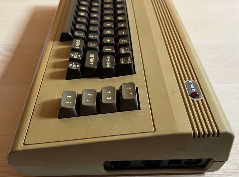
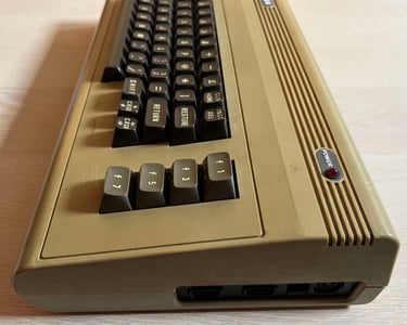
Starting point
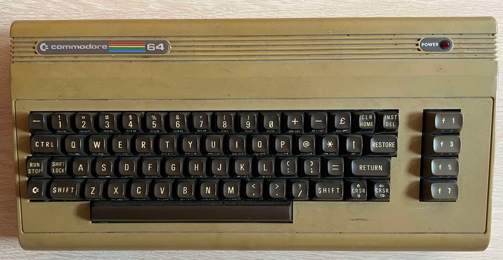
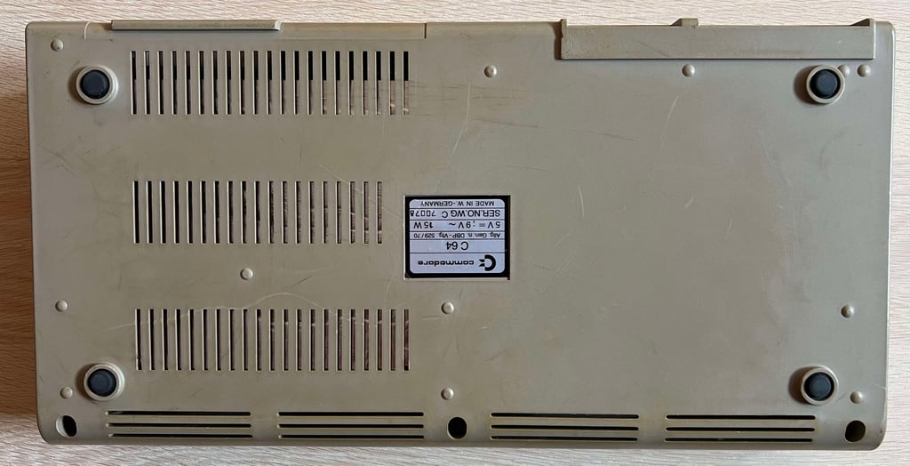
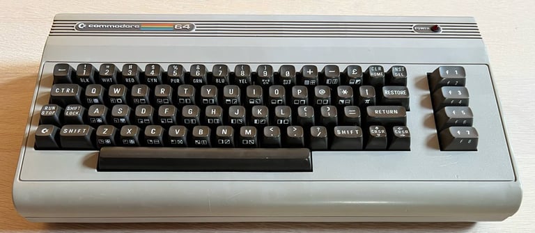
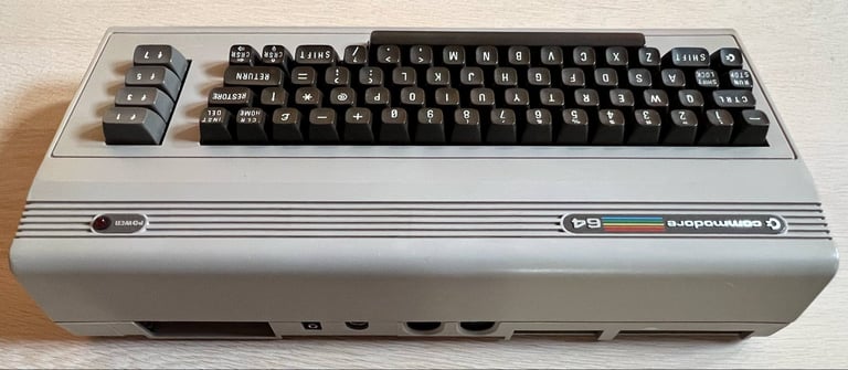
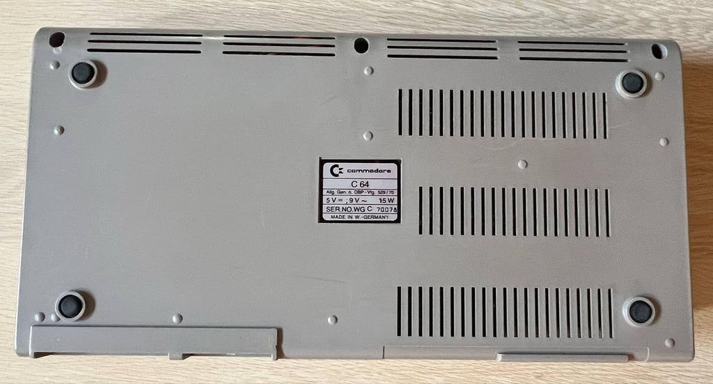
I have no idea if this machine works or not. But what I do know is that it does not look very nice... it is awfully dirty, yellowed and I can hear a rattling noise from inside the casing. Something is obviously loose inside.
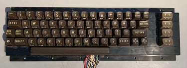
The rear of the top cover can be lifted from the bottom cover - even if the screws are still in place - since all of the plastic clips at the back are broken off. On the bright side, the keyboard appears to be mechanically working and all of the three screws at the bottom cover are in place! Nice! And the ignoring the filthy looks the machine seems to be in quite ok condition.
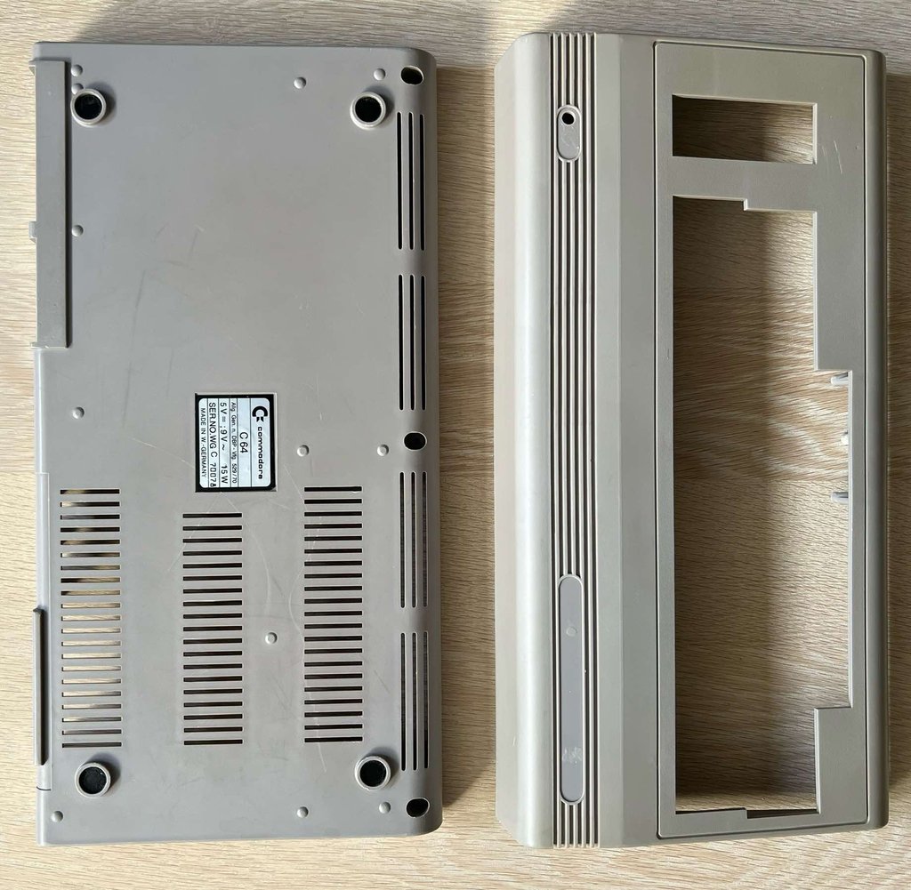
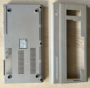
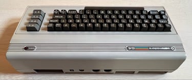
I also notice that the bottom cover is less yellowed than the top cover. It will be interested to see how it looks after retrobrighting...
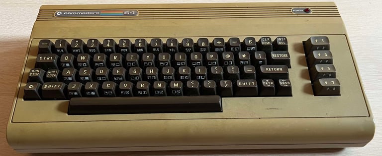
Below are some pictures before the refurbishment.


Refurbishment plan
The refurbishment plan for this C64 breadbin (several of them in parallell):
- Refurbish the casing (cleaning, repairing and retrobrighting)
- Refurbish the keyboard (cleaning, reviving the plungers and retrobrighting)
- Refurbish main board (cleaning, checking, repairing, adding heat sinks etc.)
- Replace the RF-modulator with modern replacement
- Verify operation by testing
The plan can be updated during the refurbishment process. Sometimes I discover areas that needs special attention.
Disassembly
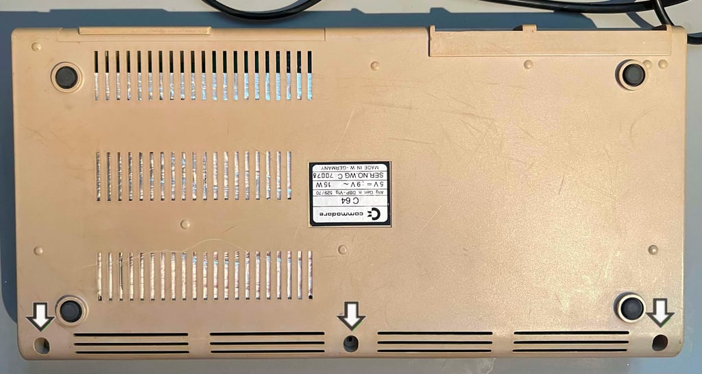
To start the disassembly of the Commodore 64 breadbin the three screws at the bottom are removed (the screws are 3.5 mm x 10 mm).
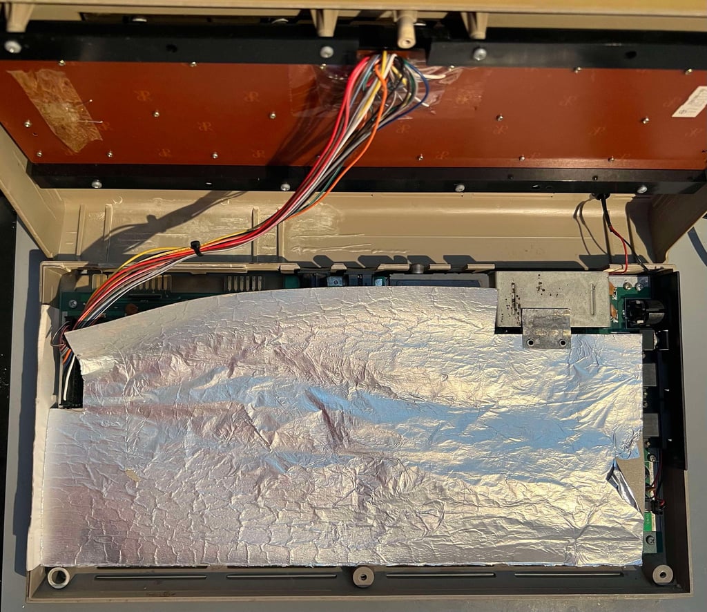
The top cover is lifted top an 90 degree angle, and the interior shield is revealed. As can be seen from the picture below the shield looks quite wrinkled. Nothing to bother with as this cover will be discarded anyway.

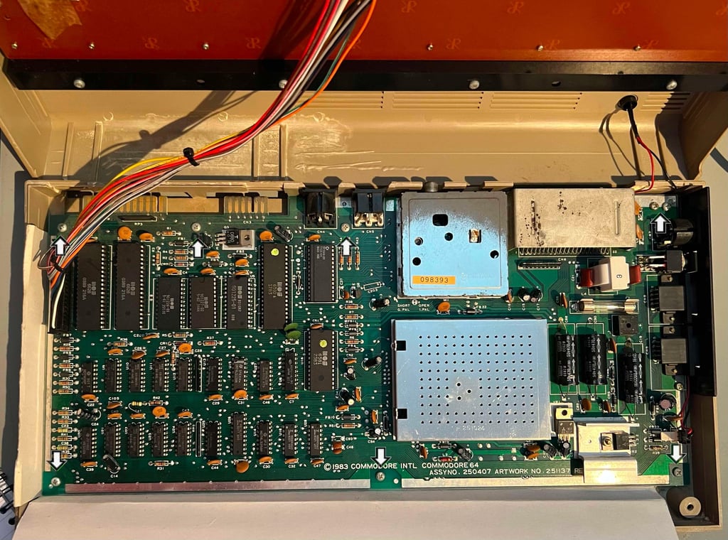
When the RF-shield is lifted away the PCB can be seen. And this is a very pleasant view - there is some dust and grease, but otherwise looks in very good condition. But I notice something strange. The LED cable is fastened beneath the PCB (and the port bracket). I have never seen this before, so I guess this is done not by the factory but by a previous owner at some time.

The seven screws (3 mm x 7 mm) holding the PCB to the bottom cover are removed. Also, the two machine screws holding the metal bracket in front of the ports are removed. This also frees the LED cable.
Notice also that the three plastic clips at the rear of the top cover is completely broken off.
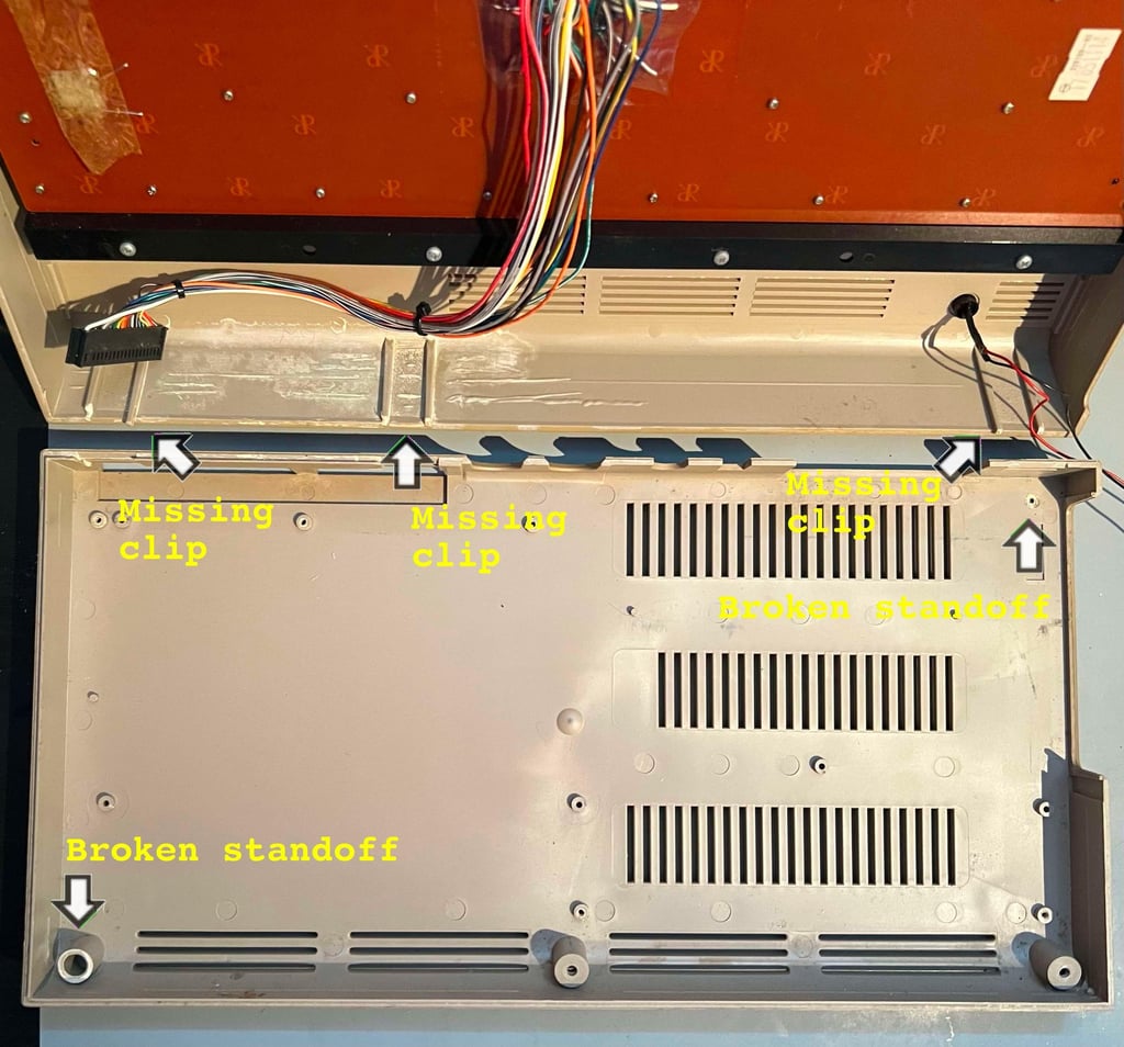
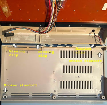
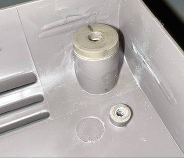
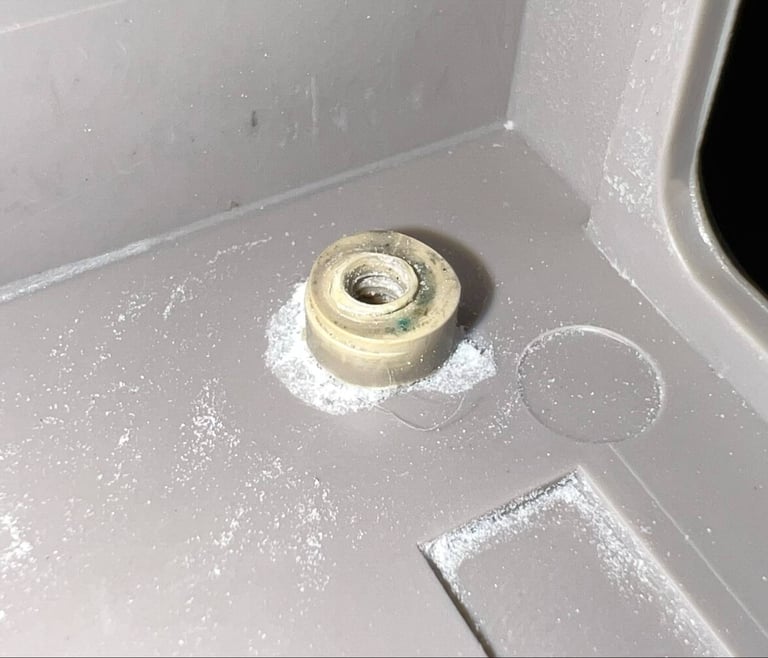
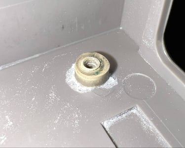
Remember the rattling sound mentioned in the first chapter? It turns out that this is caused by two broken plastic stand-offs. With some luck it should be possible to glue these back in.
Finally the keyboard is disassembled from the top cover. There are eight screws used to mount the keyboard to the cover.
Exterior casing
The covers are up for some serious cleaning. They are absolutely filthy. But a properly cleaning is not only required just to get rid of the dirt for the looks of it: it is also absolutely required as a preparation for retrobrighting later.
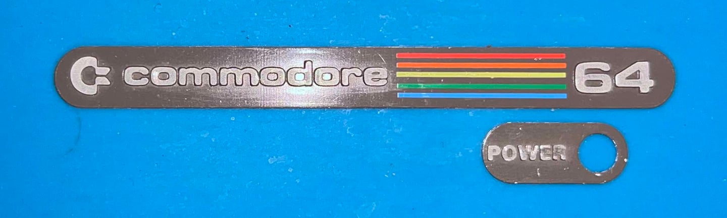
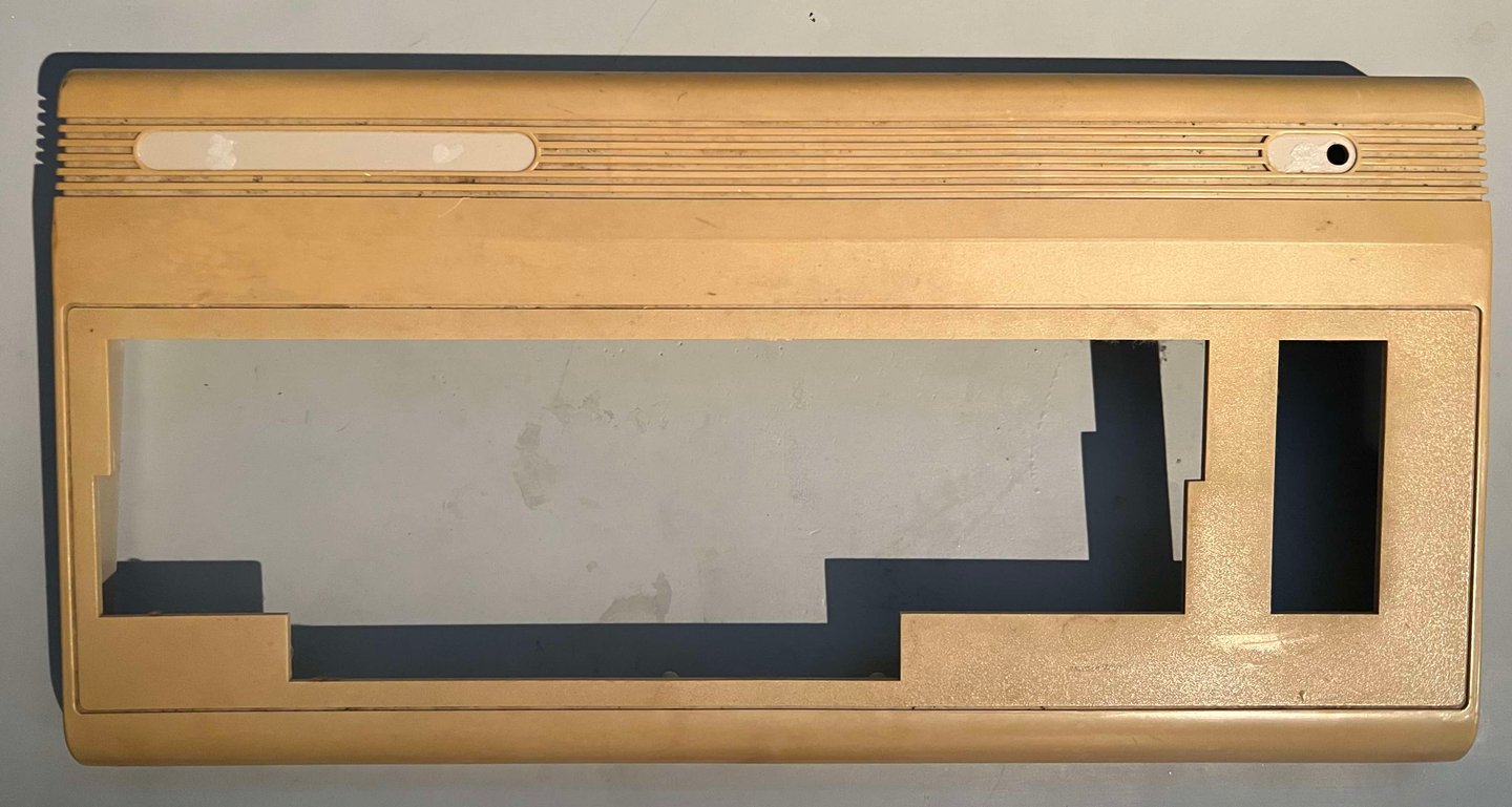
But before the cleaning, and retrobrighting, some initial steps are taken. First the "COMMODORE 64" and "POWER" badge are removed. To remove the metal badges some hot air from a hair drier is applied over the badges for a few minutes in a circular manner. This will make the glue beneath the badges to soften. With a sharp scalpel and a thin flat screwdriver the badges are gently peeled off.
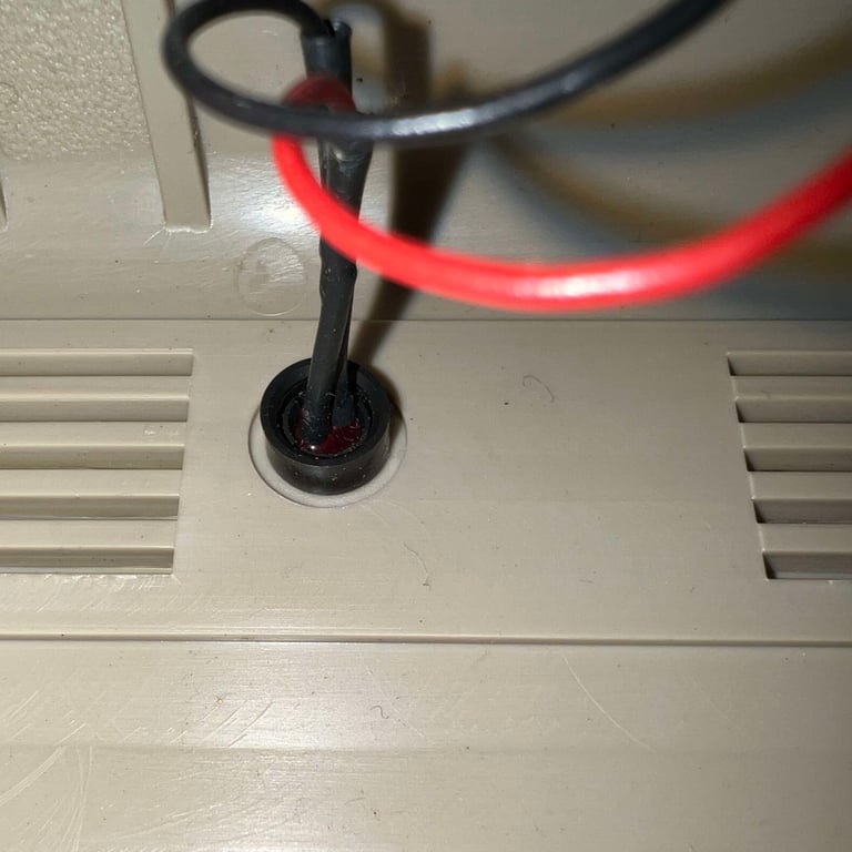
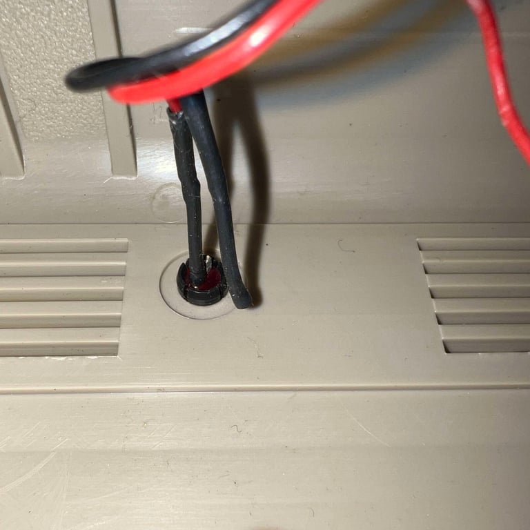
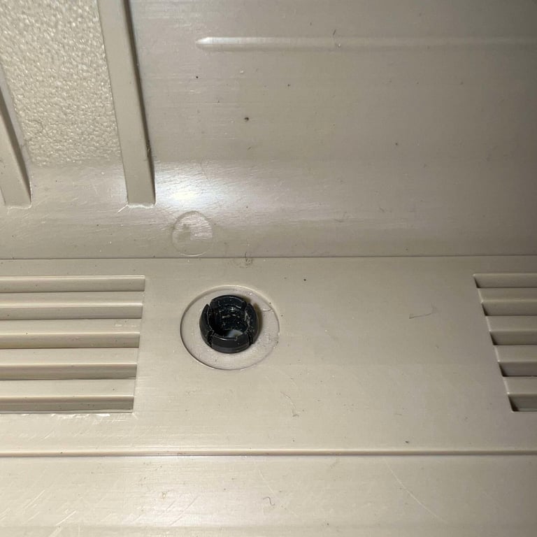
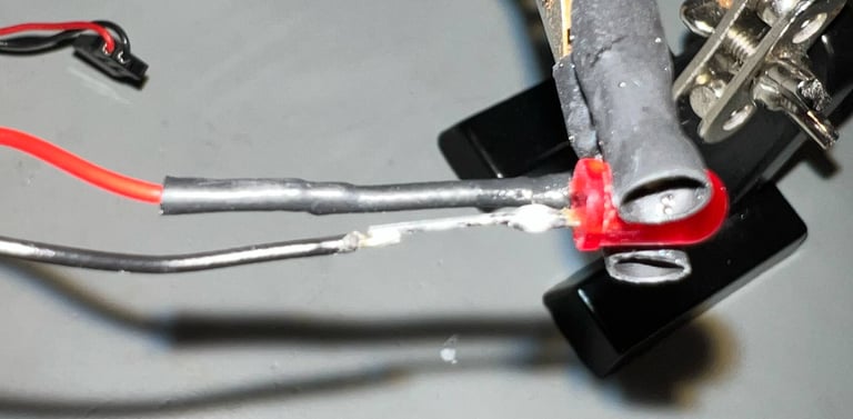
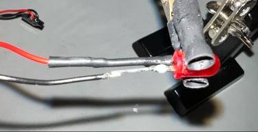
Next action is to remove the LED from the top cover. It turns out that one of the legs of the LED is broken. Or more precisely, it is likely that the leg was been marginal but the refurbish provoke it to break. This is part of the joy (?) of refurbish... Nevertheless, repairing or replacing a LED is not a big issue.
But to remove the LED it is good practice to do this in the following steps:
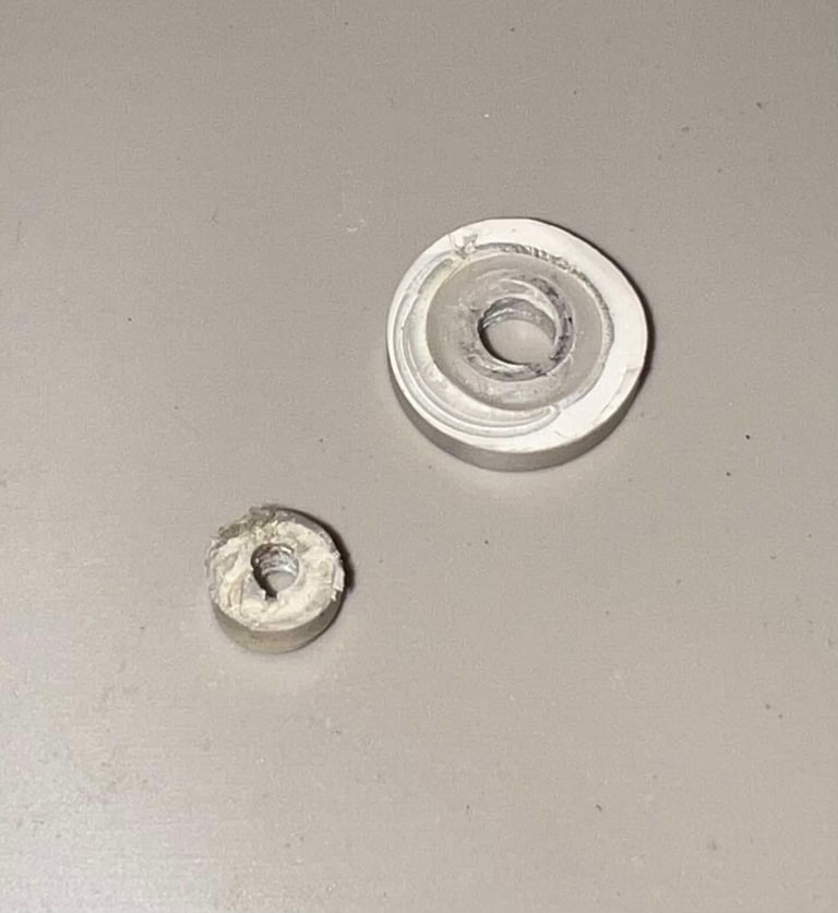
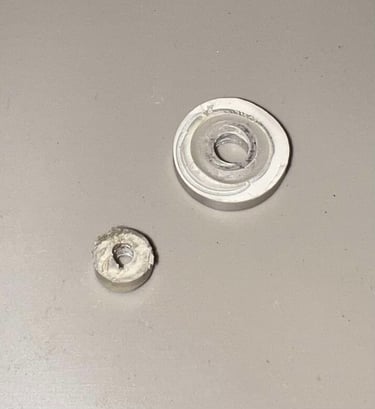
Lift the circular ring from the LED clip from the underside of the front cover
Lay the top cover with the front facing the a table so that LED is pushed towards the table. With a firm press on the LED it will pop out of the plastic clip
Remove the plastic clip from the underside of the front cover by squeezing it towards the front (can be a bit fiddly)
See pictures from the process below (click to enlarge). In the second image you can see the broken LED leg.
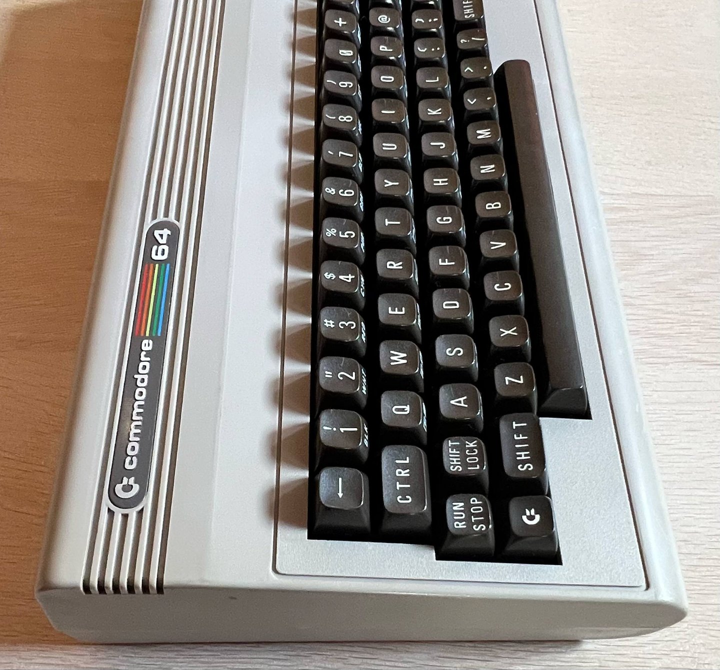
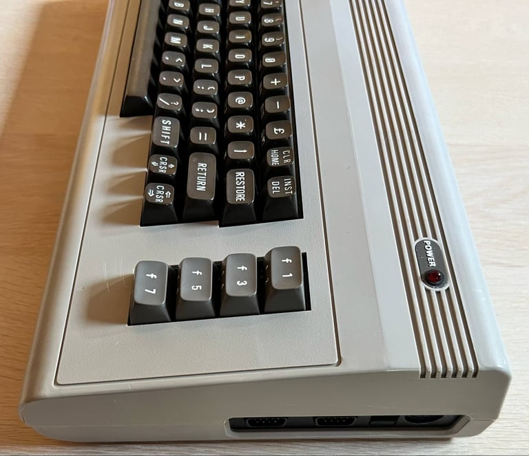
The front cover is the worst of the two covers. It will be interesting to see the result after cleaning and retrobrighting. Below is a picture of the front cover before refurbish.

Both the covers are soaked in mild soap water for about a whole week. This is probably more than required, but since the grease is so plentiful it is better to be safe than sorry.
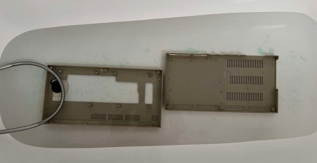
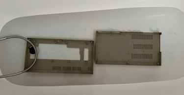
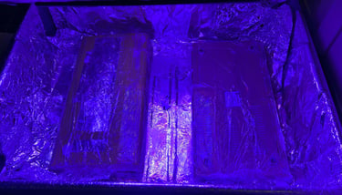
After the long bath the covers are finally cleaned with some isopropanol. This removes the remaining stains (or all that is possible to remove). Next the covers are retrobrighted for 2 x 12 hours. To retrobright I use 12 % hydrogen peroxide cream which is applied frequently during retrobrighting. The covers are wrapped in transparent plastic and exposed for UV light.

The result of the retrobrighting is quite good. Most of the yellowing is gone. Some scratches are now more noticeable than before the cleaning, but that is fine. The covers look a thousand times better than it used to.
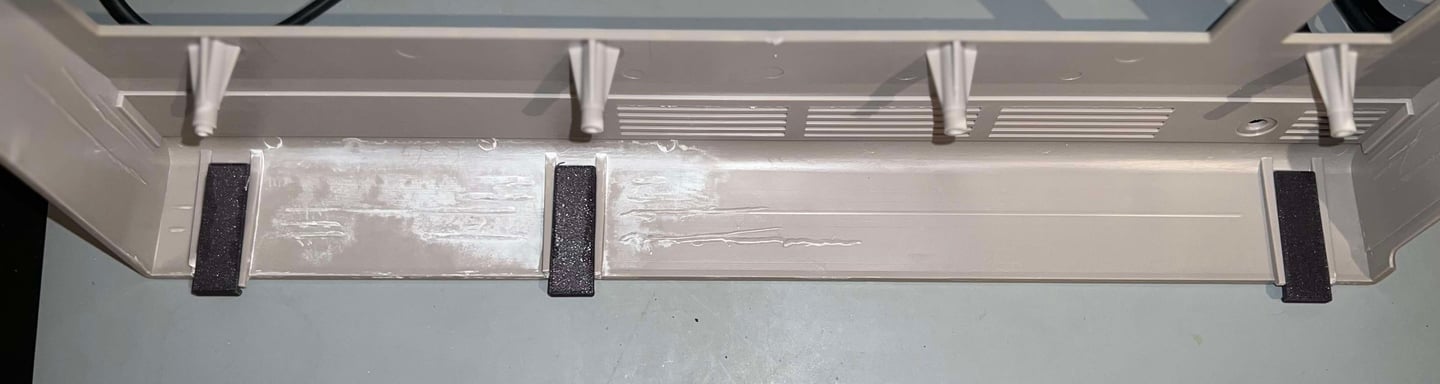
As previously mentioned, all of the three rear clips are broken. Some 3D printed tabs are glued to rear of the bottom cover (the 3D printed parts can be found from Thingiverse).
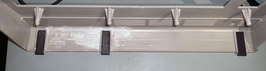
Repair - broken stems
There are two broken plastic parts in the bottom cover. With some super glue, mixed with baking soda, these are glued back in place. There is a risk that this will not last forever, but I think that this should be a quite ok repair.

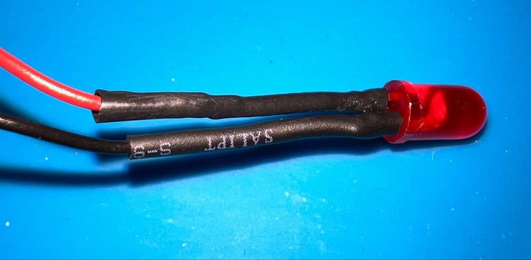
Repair - broken LED
One of the LED legs are broken. The leg is soldered back in place, and covered with heat shrink tube.

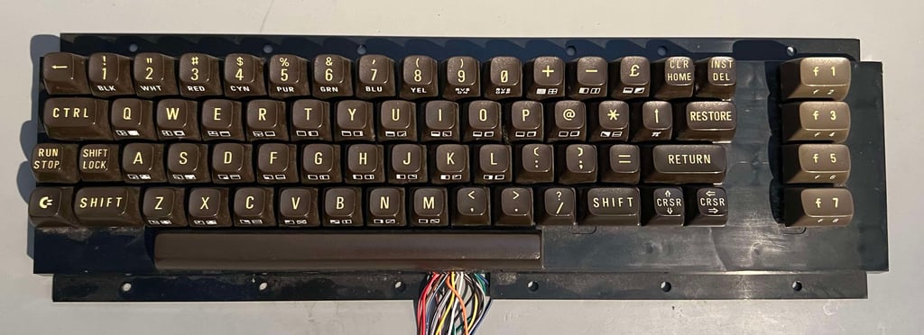
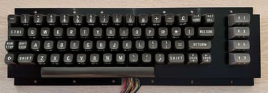
Keyboard
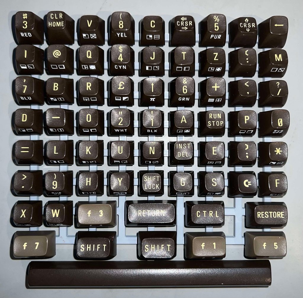
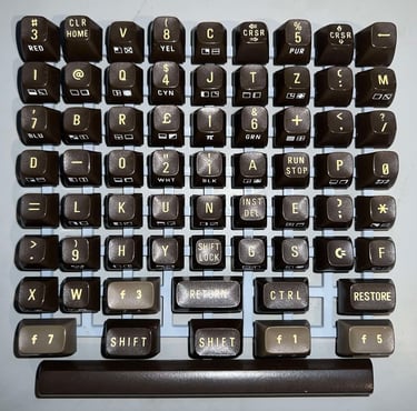
The first thing I notice is that the keyboard is less filthy than the covers. Why? I do not know. Perhaps it has been cleaned once in a while. The print on the top of the keycaps are as yellowed as the covers though.
First all the keycaps needs to be pulled off the keyboard. It is recommended to use a proper keycap puller for this purpose. Otherwise you risk damaging both the keycaps and your fingers. Beneath each keycap is a small spring, but take notice that the spring beneath the spacebar is slightly larger than the rest. So it is good practice to keep this separately to avoid mixup.
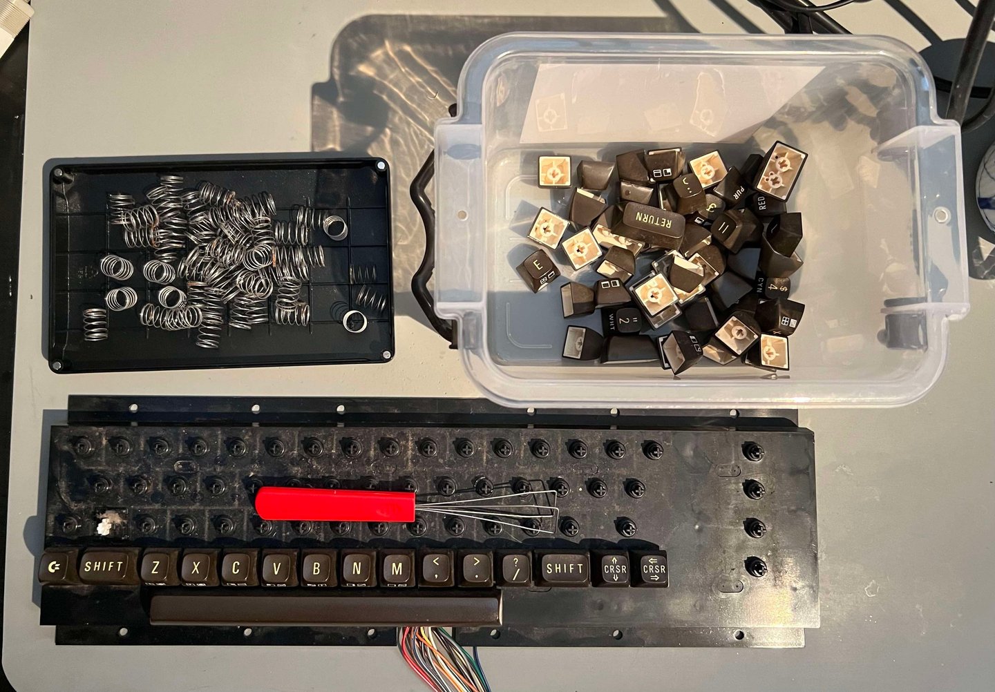

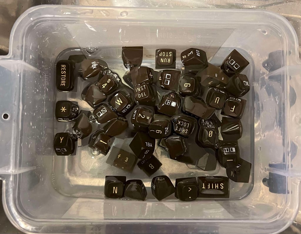
All the keycaps are placed in box filled with with mild soap water for about 48 hours. This will remove all of the grease and fat - both making them clean and prepared for retrobrighting.

Desoldering and disassembling the SHIFT-LOCK
There are two wires soldered on the backside of the SHIFT-LOCK key. It is often wise to use a desoldering pump to remove the solder, and then gently lift the two wires from the legs of the key (I often find that these are quite stuck to the legs).
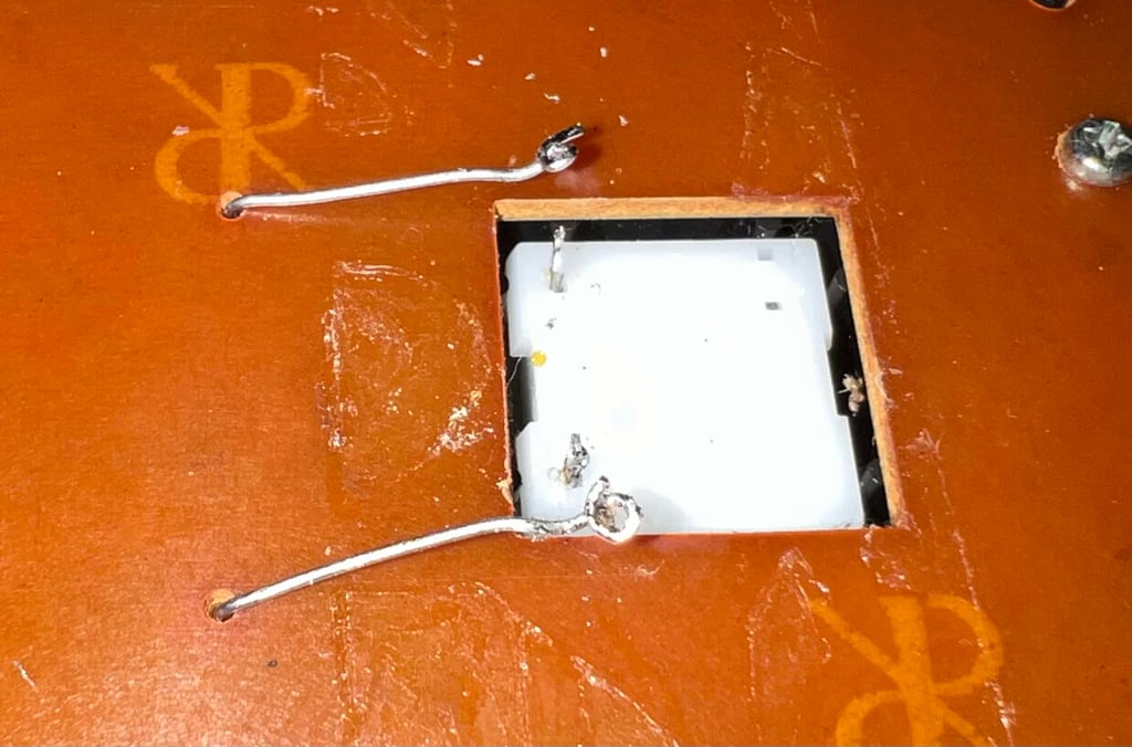
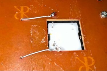
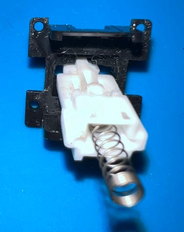
To remove the SHIFT-LOCK it is pushed firmly from the backside of the keyboard to the front. It will basically just pop-out. The SHIFT-LOCK key is properly cleaned with isopropanol and some contact cleaner.

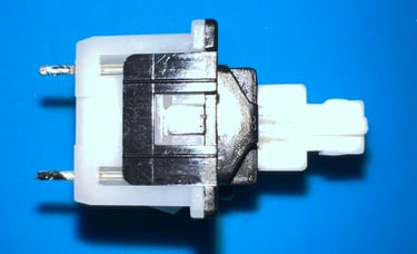
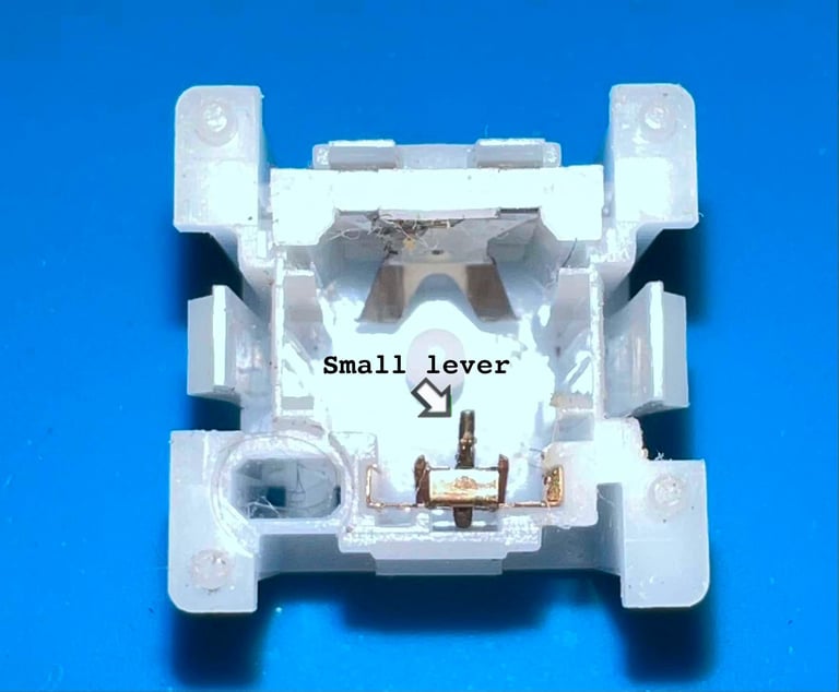
It is also good practice to disassemble the SHIFT-LOCK key and clean the interior. Opening the SHIFT-LOCK is straightforward. With a thin flat screwdriver each side of the key is pried open.
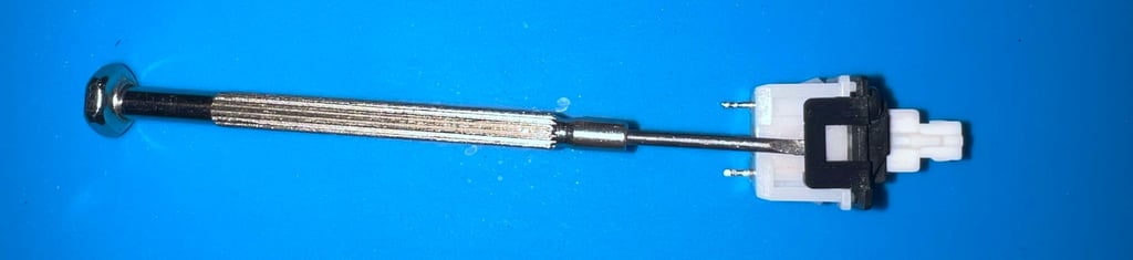

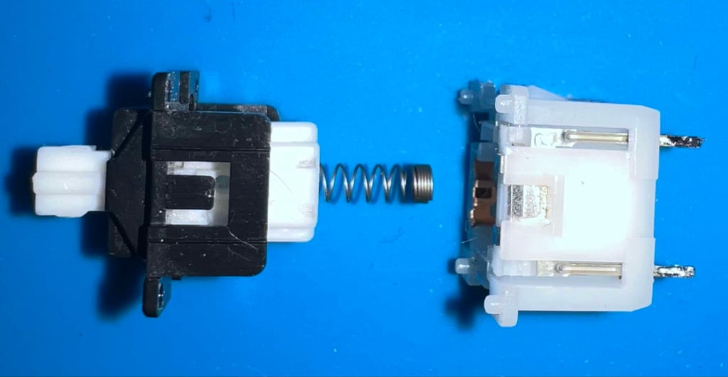
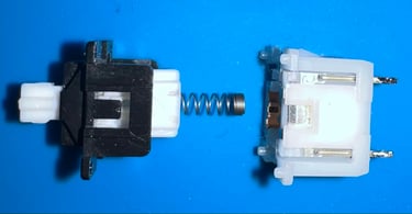
WARNING: Inside the SHIFT-LOCK key there is a small metal "arm" used to catch and lock the key in a toggle position. This is easy to both damage, and can be a bit tricky on re-assembly, so be patient and careful when refurbishing the SHIFT-LOCK key.


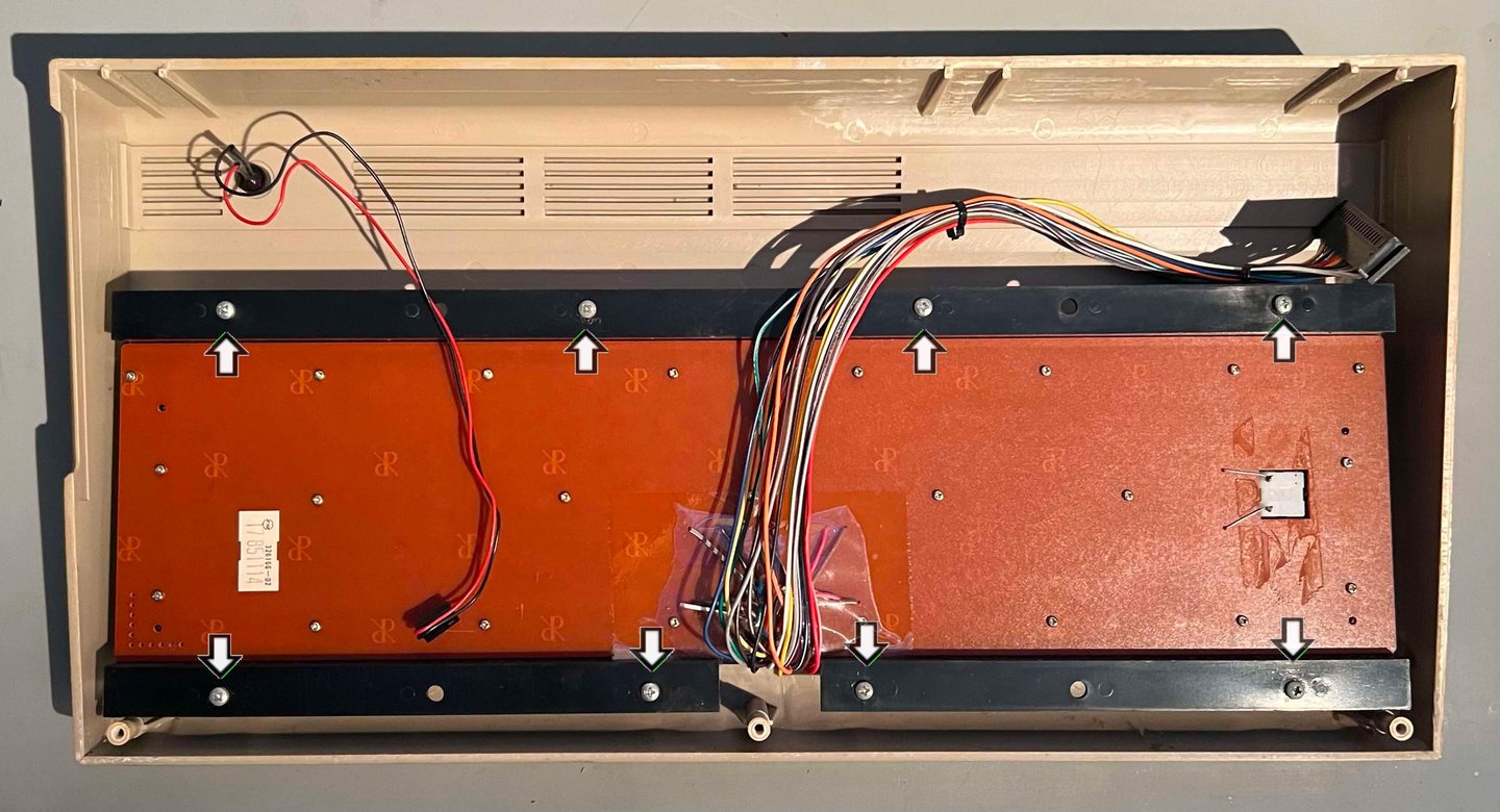
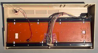
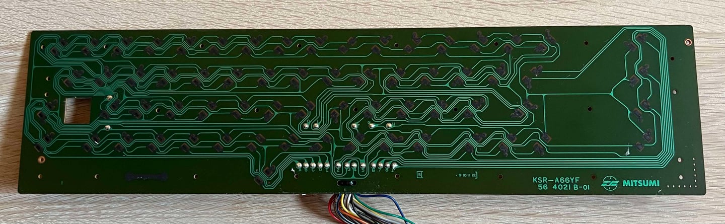
The keyboard use a hard PCB as membrane. To remove this all the small screws at the back of the keyboard are removed.

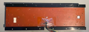
The keyboard PCB is a Mitsumi KSR-A66YF 56 4021 B-01. Notice that the last "B" in the version number indicates that this PCB use carbon pads, so to clean the PCB I use only pure distilled water - no isopropanol which can damage the carbon pads. Below is a picture of the cleaned keyboard PCB.
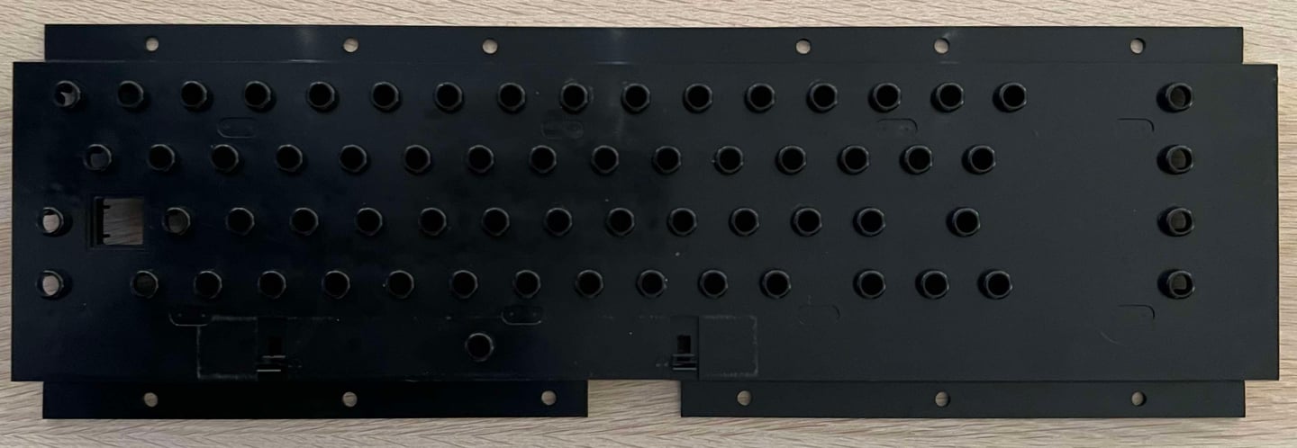
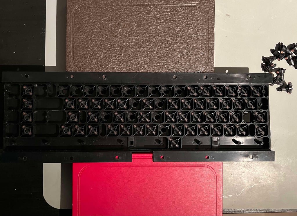
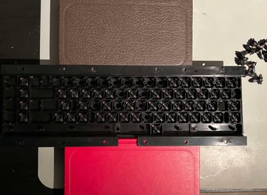
Remember the filthy plastic bracket? Well, now it looks as new! With some mild soap water all the dust and grease is gone.
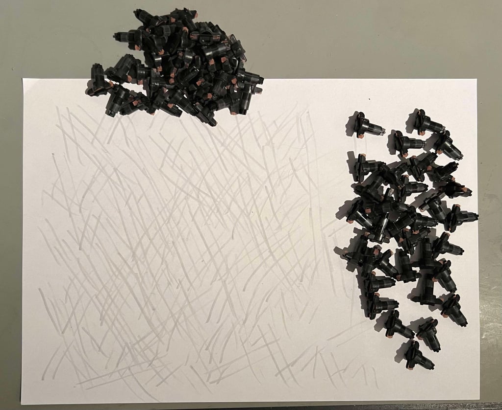
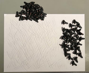
Before the plungers are put back in the plastic bracket they are "cleaned". They are not cleaned using any chemicals, but they are gently rubbed on a clean sheet of paper. It is good practice to avoid using isopropanol on the conductive rubber. This could cause deterioration of the rubber. By "rubbing the rubber" the plungers will most of the time get back to good shape - being as responsive to key presses as they were originally!
A little tip is to raise the plastic bracket when re-assembling the plungers. With a few books the plastic bracket is lifted above the table, making the re-assembly very easy.
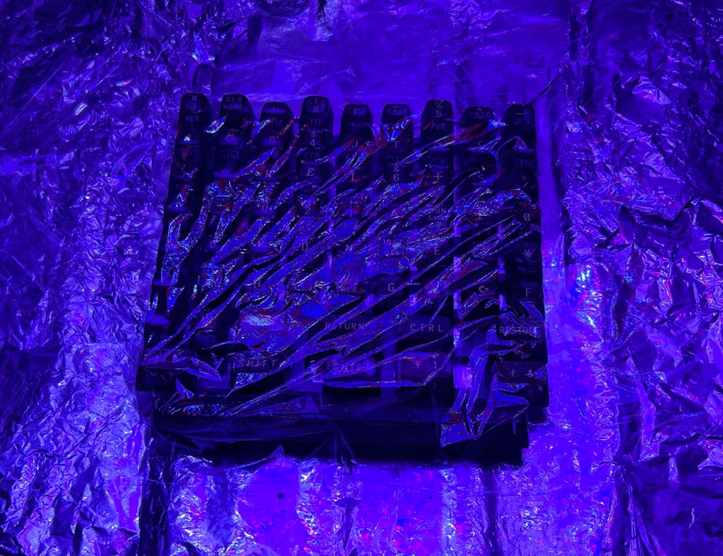
After cleaning all the keycaps are retrobrighted. This is done by first placing the keycaps on the keyboard mount.
The keycaps are smeared with 12 % hydrogen peroxide cream (aka salon cream). The cream is applied frequently to avoid dry-out while the keycaps are exposed for UV-light for about 2 x 12 hours. Note that the retrobrighting is actually done twice (each time for about 12 hours).

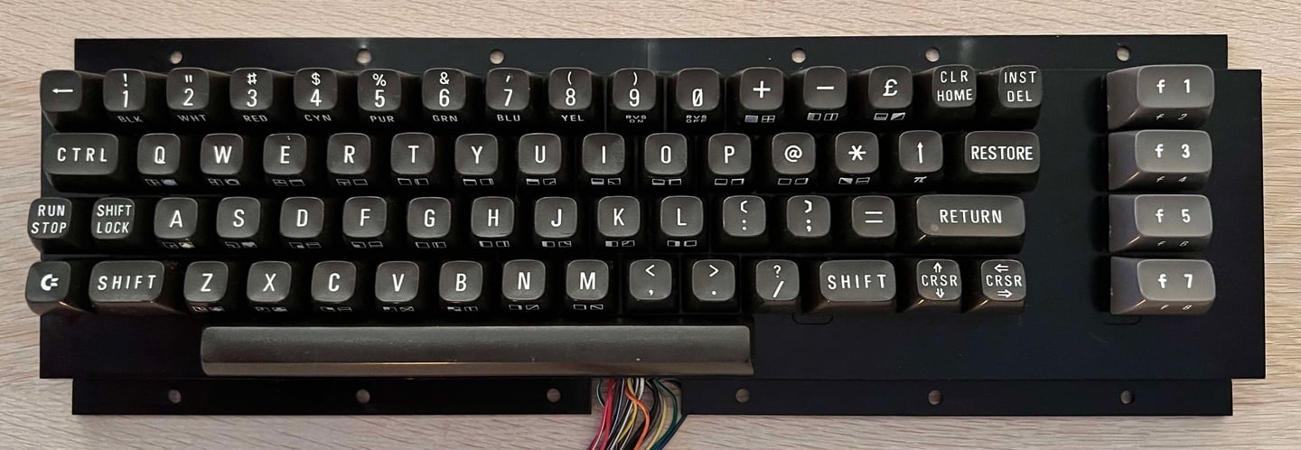
I am very happy with the result. Most of the yellowing is gone!
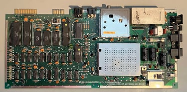
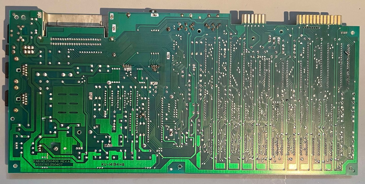
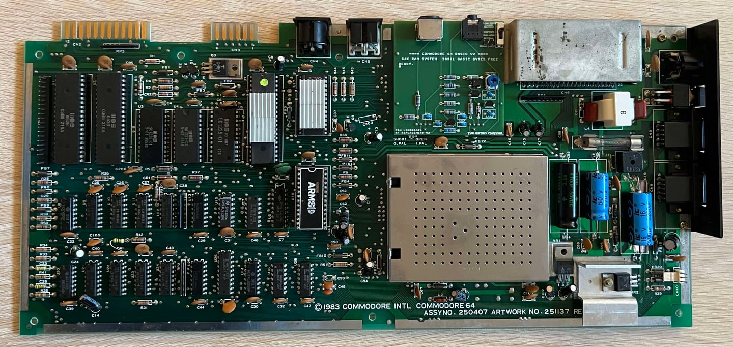
Mainboard
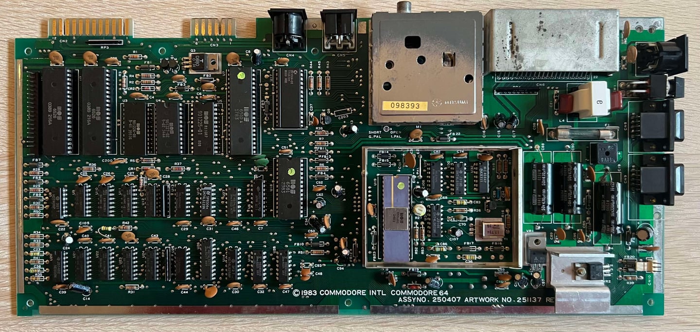
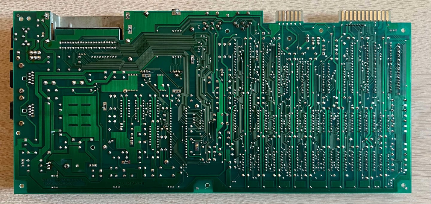
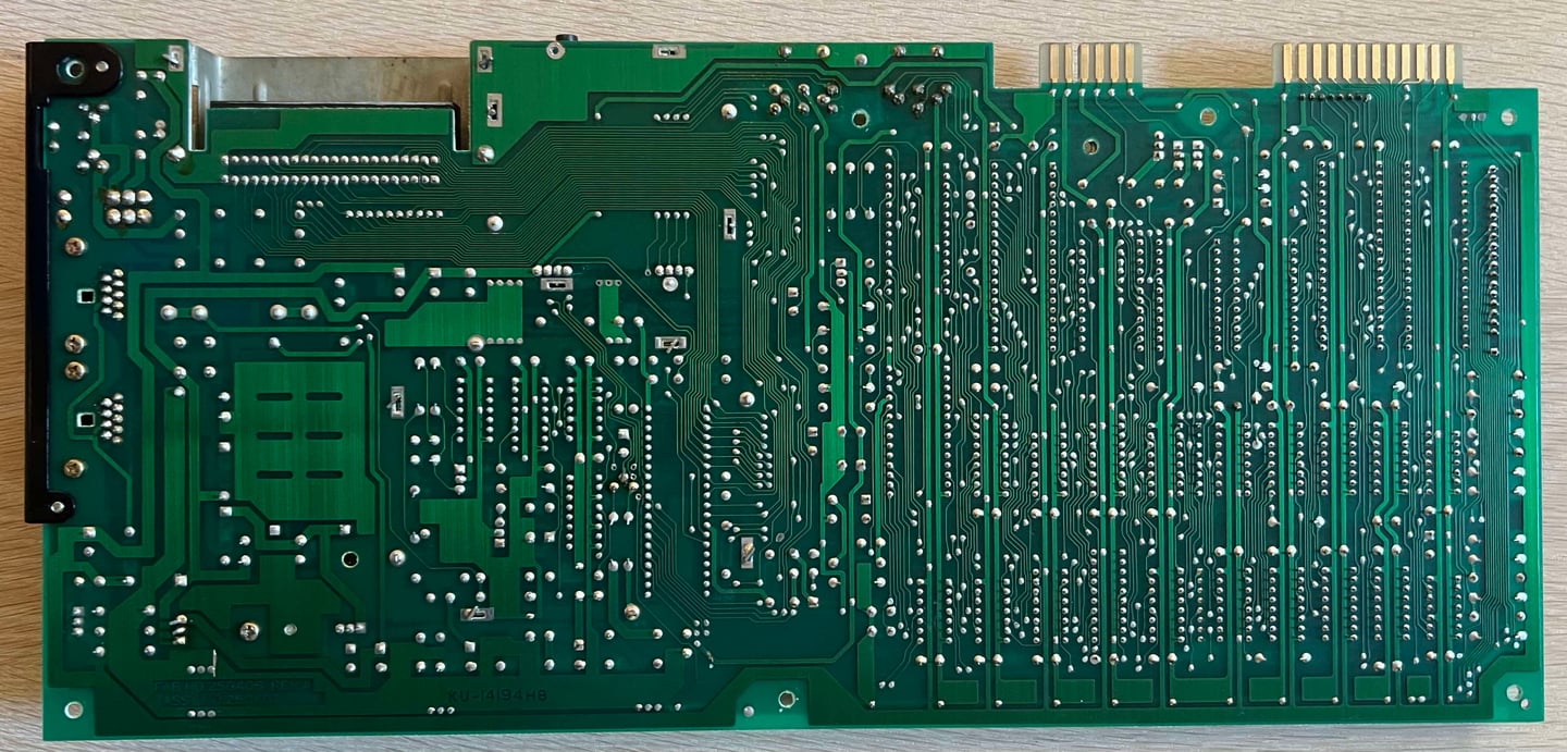
This PCBA is an Assy 250407 / Artwork 251137 (Rev B) longboard / KU-14194HB. Note that it says "KU-14194HB" on the rear of the mainboard, but this is NOT the famous early mainboard with the same assy number as far as I know. The "real" KU-14194HB has a different layout than this mainboard.
Visual inspection
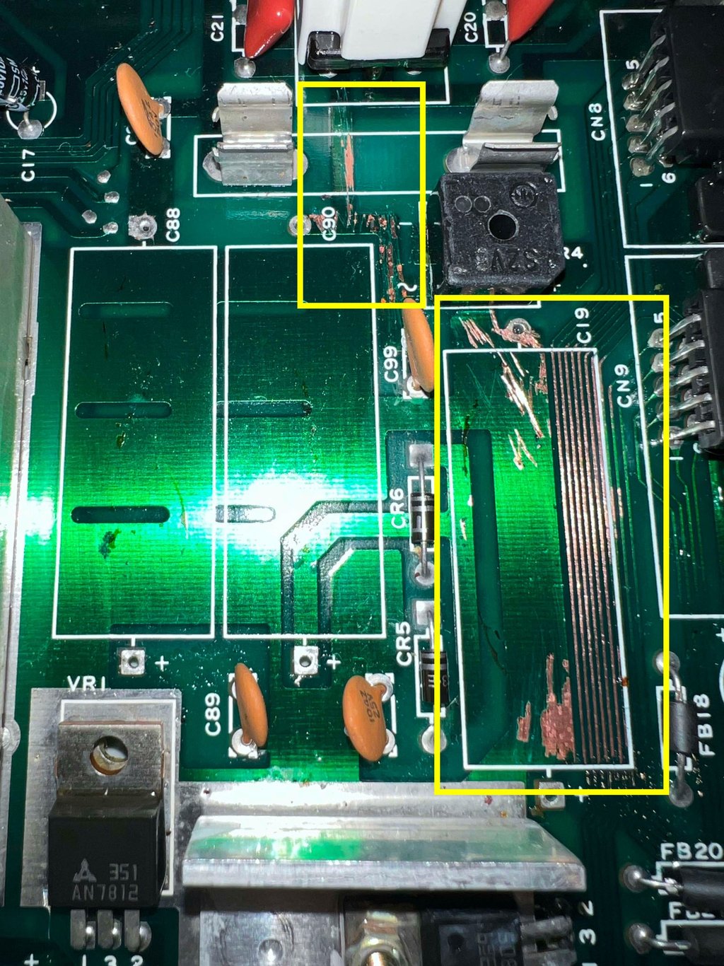
The mainboard looks to be in fine condition. I notice that there is quite some dust and grease on the top half of the mainboard, but this is to be expected since this is close to the port holes. All ICs are present. There are some signs of leakage from the large electrolytic capacitors C88, C19 and C90 can be seen. It is a bit hard to see when the capacitors are installed, but there may be some sign of corrosion on the traces beneath/beside the C19 capacitor.
Quite a few of the ICs are socketed, but this does not mean rework. For some reason (perhaps chip shortage) Commodore did socket quite a few of the custom ICs.
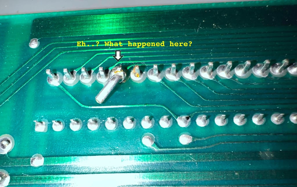
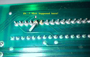
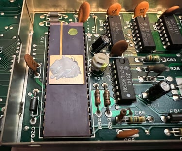
But one thing I do notice: there is almost a short circuit (!) beneath the MOS 6526 CIA #1 chip. Some small piece of metal seems to be soldered to one of the pins. This needs to be removed asap!
Below are some pictures of the mainboard before refurbishment.


A close-up of the strange soldered thing beneath the CIA #1 IC.
Cleaning the mainboard
Even if the mainboard is in quite decent condition already is cleaned with some mild soap water and a soft paint brush. Note that all socketed ICs, and the glass fuse, are removed before cleaning. It might sound strange to clean a mainboard with water (Norwegian), but that is perfectly fine. But it is important to let the mainboard dry properly before powering back on. I also think it is much more nice to work on a clean PCB than a dirty one...
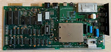
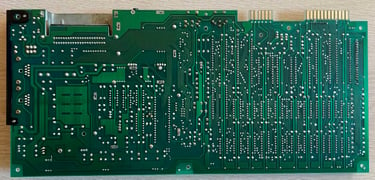
Below are some pictures of the cleaned mainboard.

In the table below the custom ICs are listed. As can be seen from the table it is likely that this Commodore 64 was manufactured sometime during the summer of 1983. But there is something pointing to another year: 1989. Both of the two MOS 6526 CIA chips are manufactured early in 1989 - and there are no signs of rework on the PCB (with the small "exception" of the weird looking metal beneath CIA #1). Could it be that the board was actually made in 1989? With most of the component from 1983? I doubt it, but I can´t prove it.
Initial testing
Before the machine is powered on it is good practice to check for short circuit on the user port (5 V and 9 V rail) with the switch in "ON" position (with no power connection). The result shows that there is no short circuit (measured: > 5 kOhm @ 5VD and > 10 MOhm @ 9 VAC).
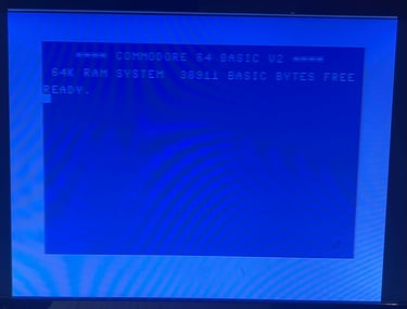
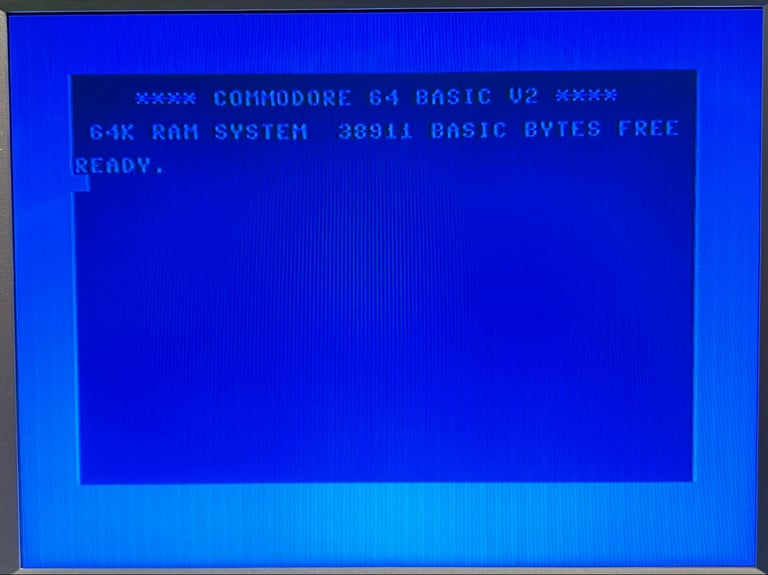
Before powering on the machine the MOS 6581 SID chip is removed with the DIP IC extractor. The SID chip is not required for the Commodore 64 to boot. When the machine is powered on the result is:
NORMAL BLUE STARTUP SCREEN WITH 38911 BASIC BYTES FREE

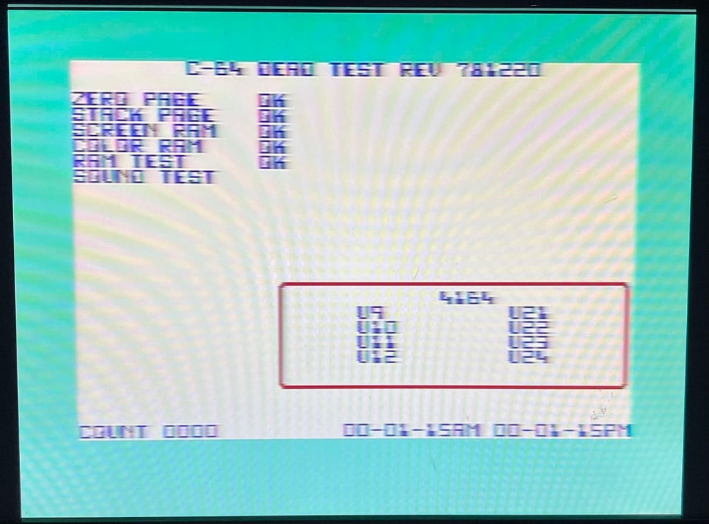
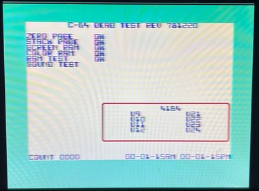
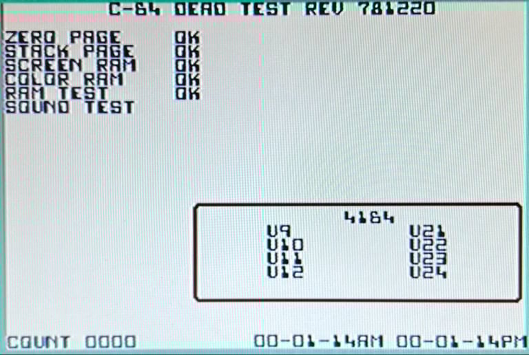
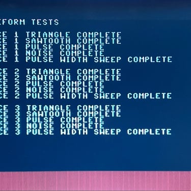
Next, the machine is tested with the Dead Test Cartridge. This will test the basic functionality of the custom chips. At this point the MOS 8580 SID chip is installed again. All tests pass - except for the sound test. There is no audio at all. Either the 6581 SID is faulty or there is something else wrong.
Checking the voltages
For the Commodore 64 to work flawlessly all the different voltages need to present and within acceptable tolerances. A detailed article on the subject can be found in the HOWTO - Checking the C64 voltages. In the table below all the measures voltages are listed (this list will also be updated after refurbishment). All the required voltages are present and within tolerances, so there are nothing obvious wrong in that area.
Replacing the SID with ARMSID
It seems like the 6581 SID gave up the ghost. There is no audio whatsoever coming from the chip. Luckily, there are some very good replacements for the SID chip. And one of these is the ARMSID.
From retrocomp.cz:
"ARMSID is "plug & play" replacement of the MOS 6581 and 8580 SID music chip used in the Commodore C64 and C128. It is a real "plug & play" solution. Just insert instead of the original SID chip into the socket and its done. Accurate sound, significantly lower noise level and less interference from the power supply than the original SID. Automatic recognition of 6581/8580 mode. You can change it anytime by using simple configuration utility to change the SID type, tune the audio filters and test your ARMSID. Lower power consumption than the original. Easy firmware update from the C64/C128 app."
As described in the text above inserting the ARMSID is "plug and play". The old MOS 6581 SID is removed and the new ARMSID installed.
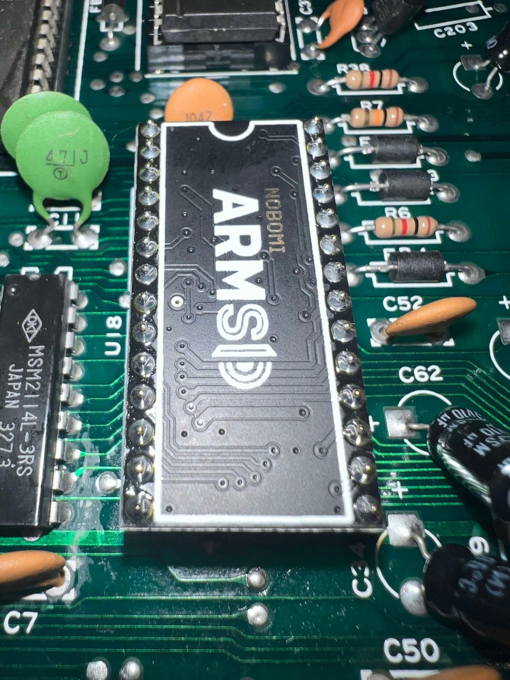

A quick check with the Dead Test Cartridge shows that the ARMSID works. A more thorough test will be done later, but there is no problem whatsoever with the sound using the Dead Test Cartrigde.
Replacing the RF-modulator
The RF-modulator is responsible not only for providing a RF-audio/video signal:
From The Retro Channel GitHub page:
"The RF modulator in the C64 handles amplification and filtering for all video signals (including the ones on the C64 DIN connector). Unfortunately it does a very poor job and this is even more apparent with modern displays and upscalers, even CRTs with their inherent softening can reveal issues with the original RF modulator. One way to signifcantly improve the video output is to replace the RF modulator with a more modern and finely tuned solution, and why not add a few quality of life features while were at it."
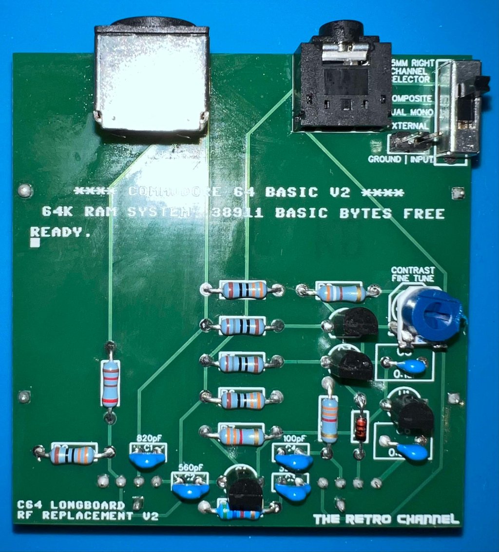
The author of The Retro Channel has designed a RF-modulator replacement which gives superior video output compared to the original RF-modulator. You can read more about it, and find information about all the required parts on the GitHub page here: https://github.com/TheRetroChannel/Commdore-64-RF-replacement-Longboard-V2.
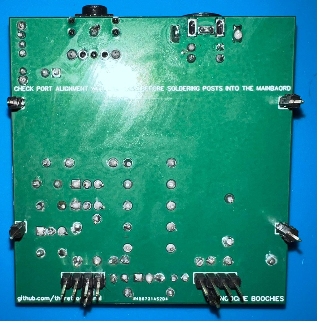
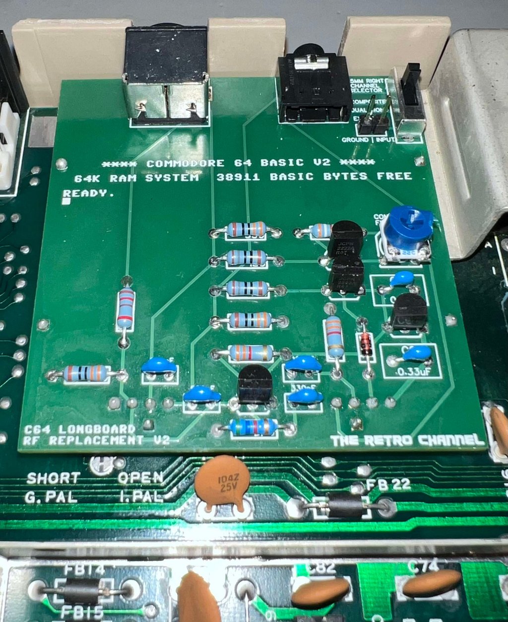
All parts are sourced from Mouser, AliExpress and PCBWay as described from the GitHub instructions page. Below is a picture of the PCB with the components after I have assembled and soldered everything.


Desoldering the original RF-modulator and soldering the repacement
This Commodore 64 is equipped with a RF-modulator from Mitsumi (MD6-UE3603), and this needs to be removed before the new modern RF-modulator can be used.
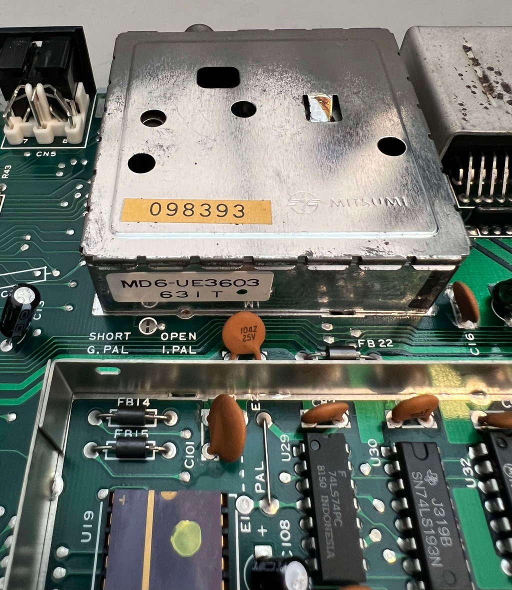

Desoldering the original RF-modulator is not particularly difficult, but it is by no means trivial. If you have plans of desoldering a RF-modulator for the first time I would recommend the HOWTO article "Desolder the RF-modulator" to avoid any damage to either the mainboard or the RF-modulator module. Below is a picture of the mainboard with the RF-modulator desoldered. No traces or pads were damaged during the process.

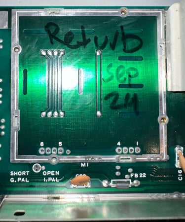
The new RF-modulator replacement is soldered in (and also checked that the height is ok for the outputs to be reached from the bottom cover).

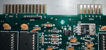
Cleaning the user- and datasette connector
So easy, but so effective. Cleaning the user- and datasette connector is probably the simplest thing you can do, but can reduce the risk of "?LOAD ERROR" and peripherals not working.
But to clean the golden connectors it is wise to NOT use a glass fiber pen unless you need. Try first with a normal rubber eraser (yes, bring your great good-smelling-erasers from the 80s). Using the rubber eraser most of the surface oxidation and grease will come off. Finally, some isopropanol is used to clean the final residue.
Below is a picture of the cleaned connectors. Notice that there are some horizontal scratches on the user connector, but I think it is only surface deep.

Replacing broken (?) electrolytic capacitors
Usually I replace all the electrolytic capacitors, but recently I have changed my mind. Even if electrolytic capacitors are prone to dry out, I hardly ever see this on Commodore 64 machines. It is not so that it never happens, but I think it is less usual than you would expect. Could this also be related to the fact that most machines I repair are used in Norway (not the warmest country in the world)?
Nevertheless, if there are signs of broken / leaking capacitors I will replace them. And the three large electrolytic capacitors C19, C88 and C90 have been leaking and must be replaced.
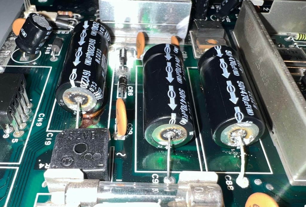
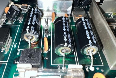
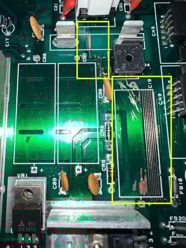
Desoldering corroded capacitors is challenging since the solder will not "grip". But using a sharp scratching needle most of the corrosion is removed, and fresh solder is applied. Now the electrolytic capacitors can be removed. With the capacitors out of the way the area is rinsed with some vinegar first. This will neutralise the corrosion. There are two areas where there are some corrosion (see the two squared areas below). Both of these areas are scraped and cleaned properly to prevent further corrosion. Finally, some transparent nail polish is applied to the traces to seal the exposed copper.
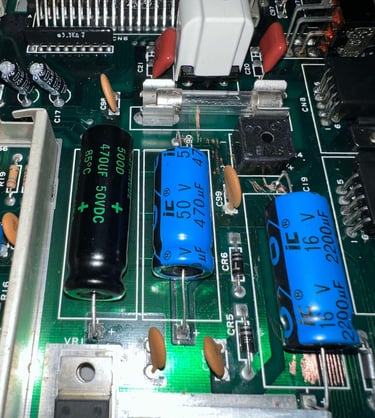
Three new electrolytic capacitors are installed: 2 x 470 uF [50V] and 1 x 2200 uF [16V].

Heat sinks
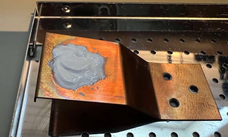
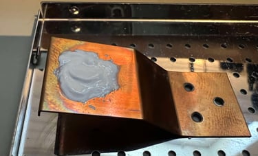
Some of the custom MOS ICs are running quite hot. And without good heat dissipation there is a risk that the longevity is reduced. Therefore heat sinks are added to the MOS 6510 CPU and the 251064 PLA ICs Normally, the MOS 6581 SID IC is also heat sinked, but since this is now replaced with a modern ARMSID this is no longer required. The last IC which is running very hot is the MOS 6569 VIC-II. This IC is placed within a metal can functioning both as RF-shield and heat sink. But for the heat sink to work with the metal can some new heat paste are applied (only a thin layer is required - to even out any small gaps between the metal on the IC and the top lid).

Below are some pictures of the mainboard after the refurbishment. As can be seen the heat sinks are now in place.
Testing
Proof is in the pudding - does it work?
Testing is done through three main stages:
Testing the basic functionality and chips
Testing the complete set of custom ICs and I/O ports
Testing by using the machine playing demos, games etc. accessed by both floppy and datasette to verify correct operation
Basic functionality and chips
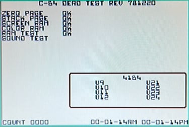
First test is done using the Dead Test Cartridge. This test doesn´t test all the functionality of the Commodore 64, but it does test the basic functionality of the major chips such as the CIA #1/2, CPU, VIC-II, PLA, RAM and SID. As the picture shows below all tests pass.
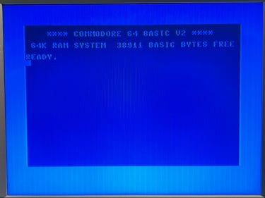
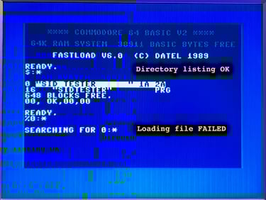
Next test is to power the Commodore 64 to the blue boot up screen and also check the keyboard to make sure all keys works as they should. Only one of the two tests pass; the blue startup-screen showing 38911 BASIC Bytes Free. Loading a directory is working as it should, but loading a file fail. So something is rotten in the state of...

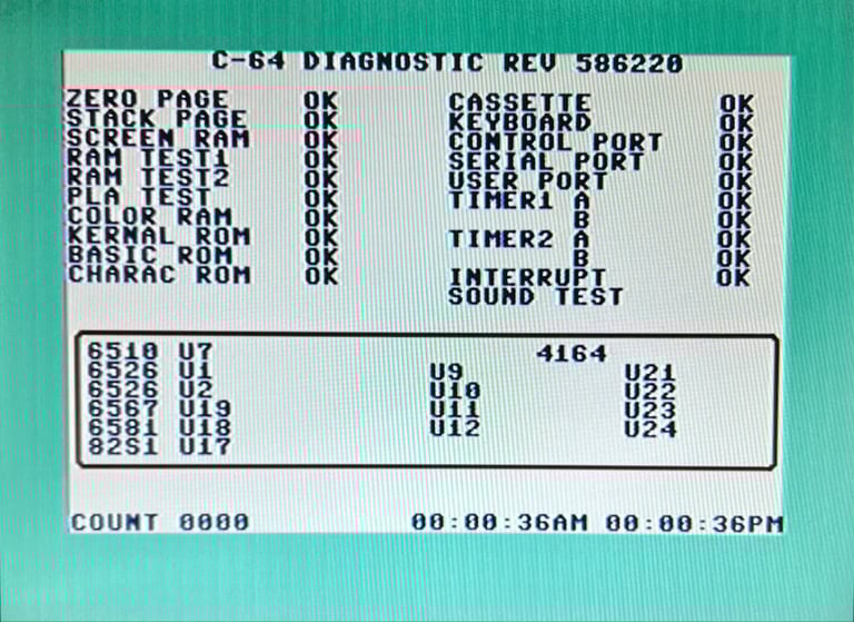
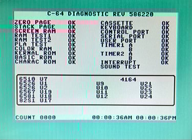
Diagnostics test with harness
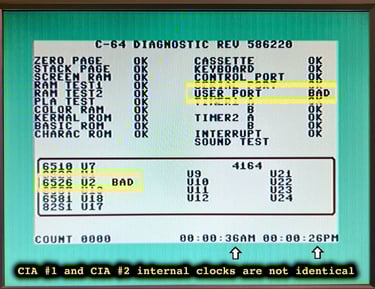
To test all the custom ICs, and I/O ports, the Diagnostics cartridge is used. The Diagnostics cartridge is very valuable when the complete test harness i installed as in "everything" is tested formally. As can be seen from the picture below, two faults (interrelated) issues are identified:
USER PORT reported as BAD
The two CIA counters are not identical AM >> PM
Also, as can be seen from the picture below the Diagnostic cartridge software report the the 6526 U2 IC to be BAD.

Repair
CIA #2 - Common denominator?
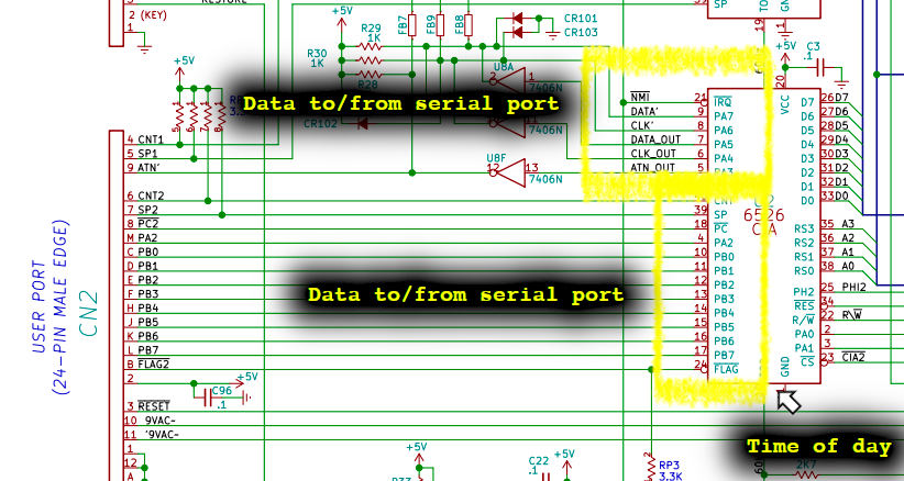
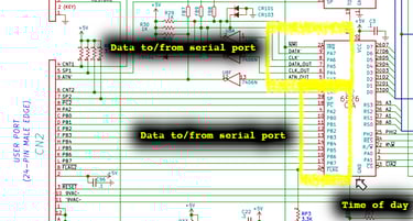
The Diagnostic cartridge indicates that the MOS 6526 CIA#2 (U2) is bad. And there is a relation with CIA#2 to both the User Port and the Serial port (for the floppy drive). From the schematics for assy 250407 we see that the CIA #2 is connected directly to the User Port and Serial port, and also the Time of Day (TOD) is directly connected to the CIA #2. See schematics below.
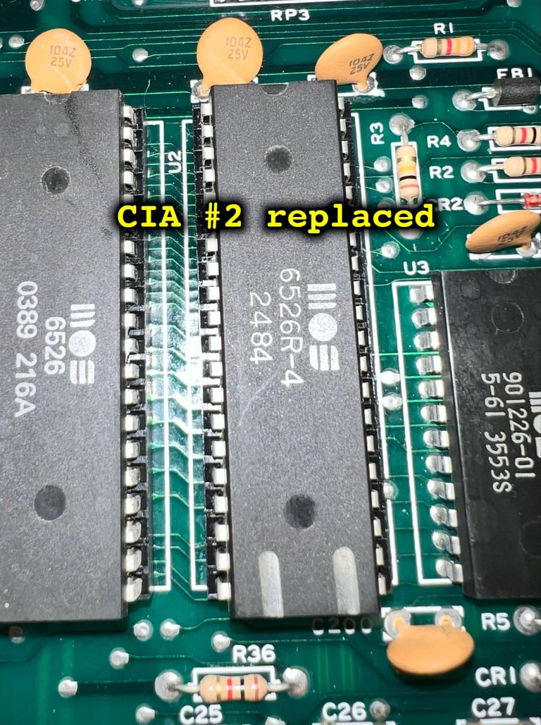
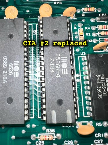
The MOS 6526 CIA #2 (U2) is in a socket, so testing with a known-working CIA IC (from 1984) is done without any soldering. And, yes (!), replacing the CIA #2 with a new MOS 6526 fixes the problem. As can be seen from the picture below, the Diagnostics cartridge test pass with flying colors.
Testing - continued
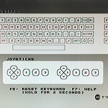
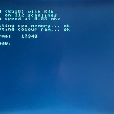
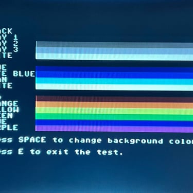
Now that the machine is repaired the testing continues. The keyboard, memory and basic audio/video are tested with different software tools. They all pass the tests (click to enlarge picture).
Extended testing
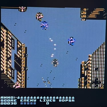
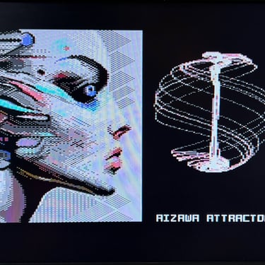
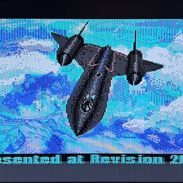
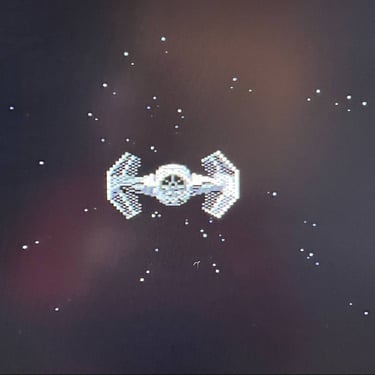
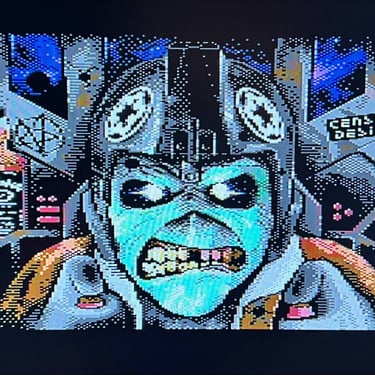
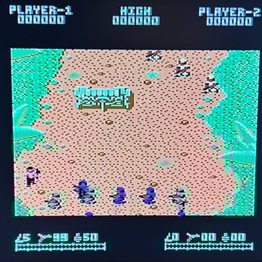
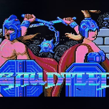
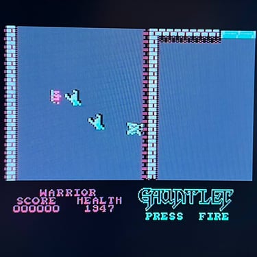
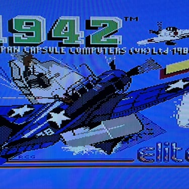
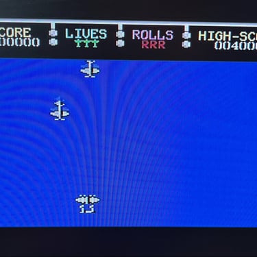
Knowing that the basic functionality of the machine works I continue the testing by using the Commodore 64 for normal operations; playing some games, watching demos, loading from datasette and floppy and using a cartridge. I can not find any issues with this machine. I also pay special attention to the video to make sure that there are no glitches in the graphics - I can´t see any abnormalities. Below is a gallery with pictures from the testing.


Final result
"A picture worth a thousand words"
Below is a collection of the final result from the refurbishment of this C64 breadbin. Hope you like it! Click to enlarge!


Banner picture credits: Evan-Amos