

C64 Breadbin [PAL]
Ser. No. 86104
Assy 250407
Artwork 251137 (REV B)
Starting point
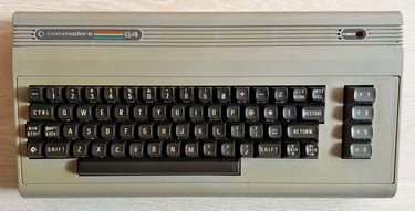
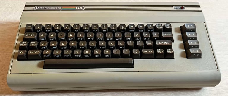
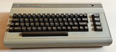
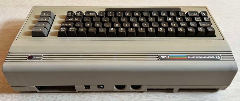
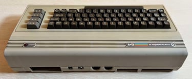
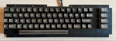
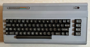
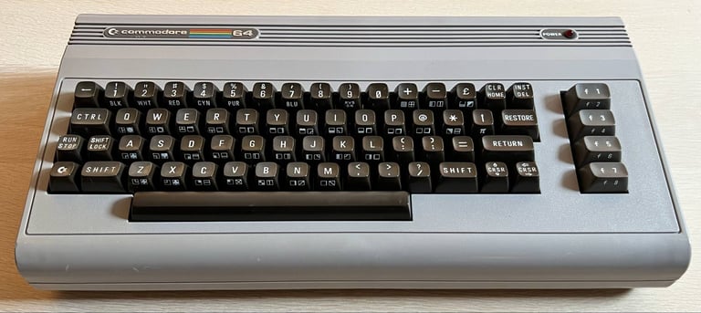
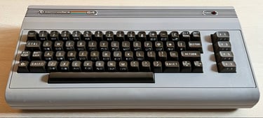
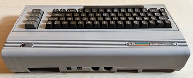
This Commodore 64 breadbin is in for both repair and refurbish. The audio is reportedly not function as it should, and there could be some other issues as well - it is also reported that the video picture appear "double" when using RF output, but we´ll find out as the refurbish unfolds.
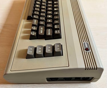
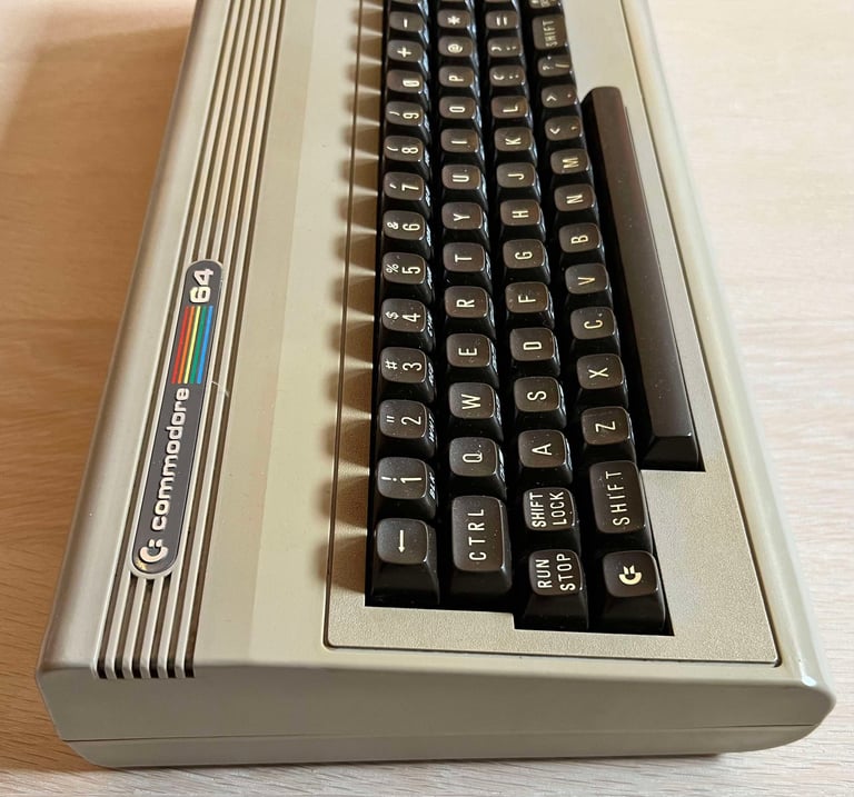
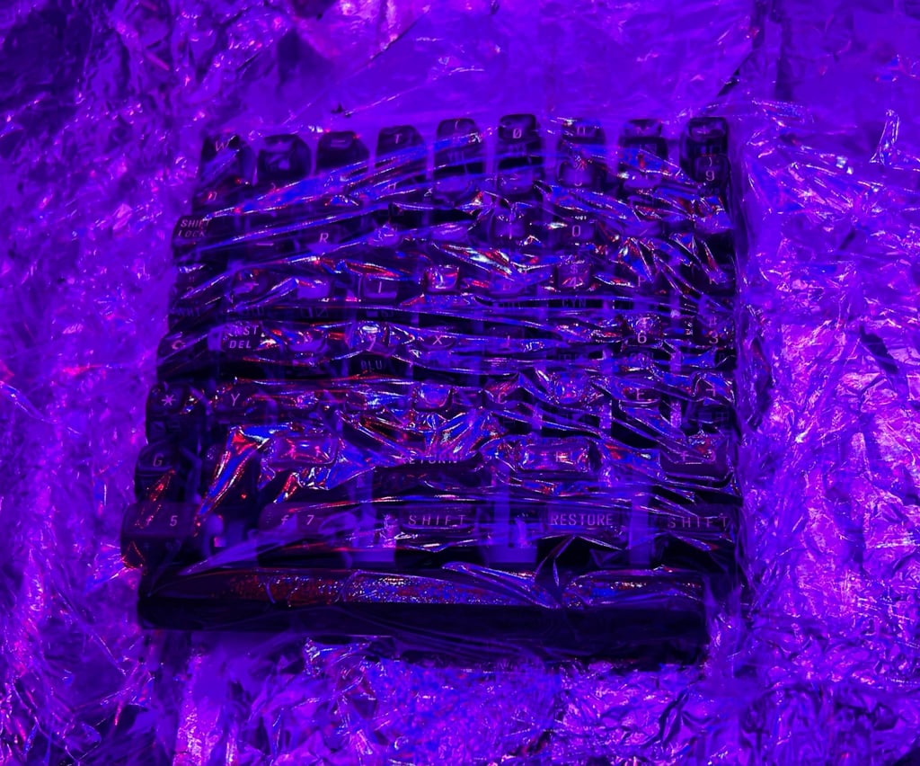
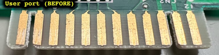
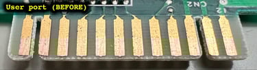
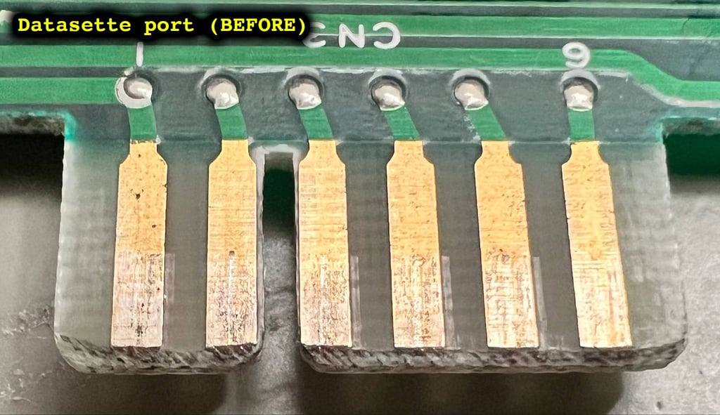
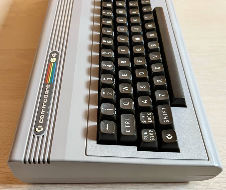
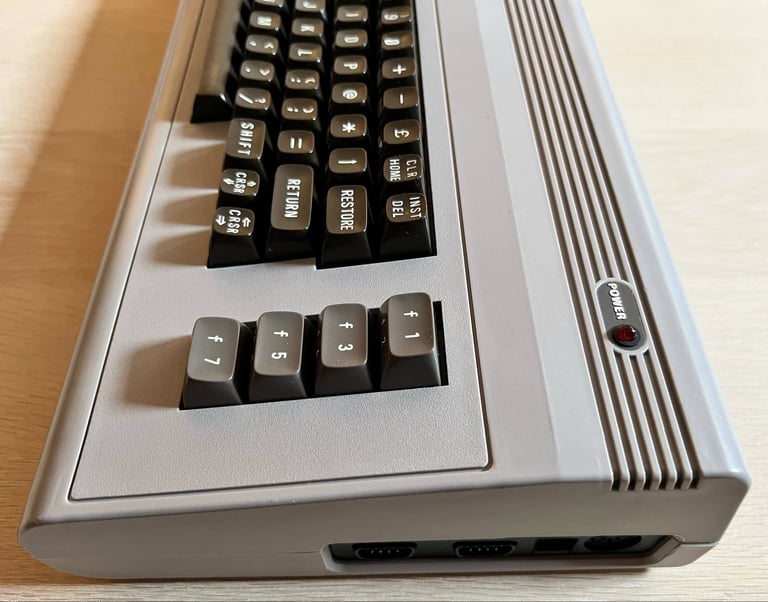
From the outside the machine looks to be in very good condition. Yes, there are some dirt and grease - and the casing and keycaps are quite yellowed - but otherwise it seems to be taken good care of. I do notice that there is quite some dust in the rear ports (user port, datasette and cartridge), but hopefully the accrued moist in the dust has not made any corrosion. There are some signs of wear, but they are really marginal. I think this will be a very good looking (and working) machine when the refurbish is complete.
Below are some pictures of the machine before refurbish.


Refurbishment plan
The refurbishment plan for this C64 breadbin (several of them in parallell):
- Refurbish the casing (cleaning, repairing and retrobrighting)
- Refurbish the keyboard (cleaning, reviving the plungers and retrobrighting)
- Refurbish main board (cleaning, checking, repairing, replacing capacitors and voltage regulators if required, adding heat sinks etc.)
- Recap RF-modulator
- Verify operation by testing
The plan can be updated during the refurbishment process. Sometimes I discover areas that needs special attention.
Disassembly
Covers and PCB
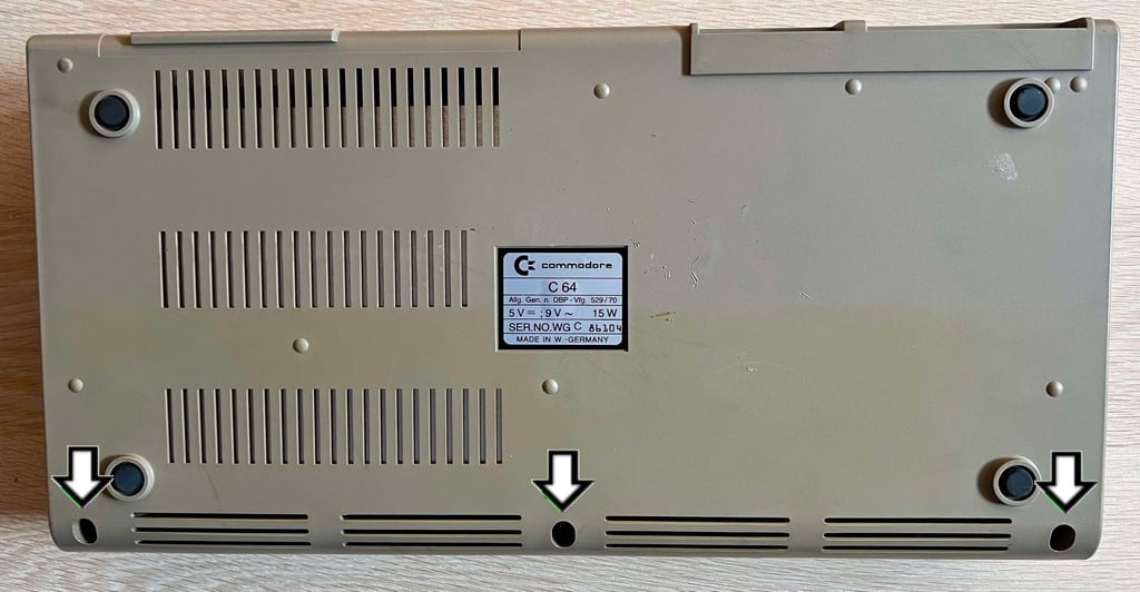
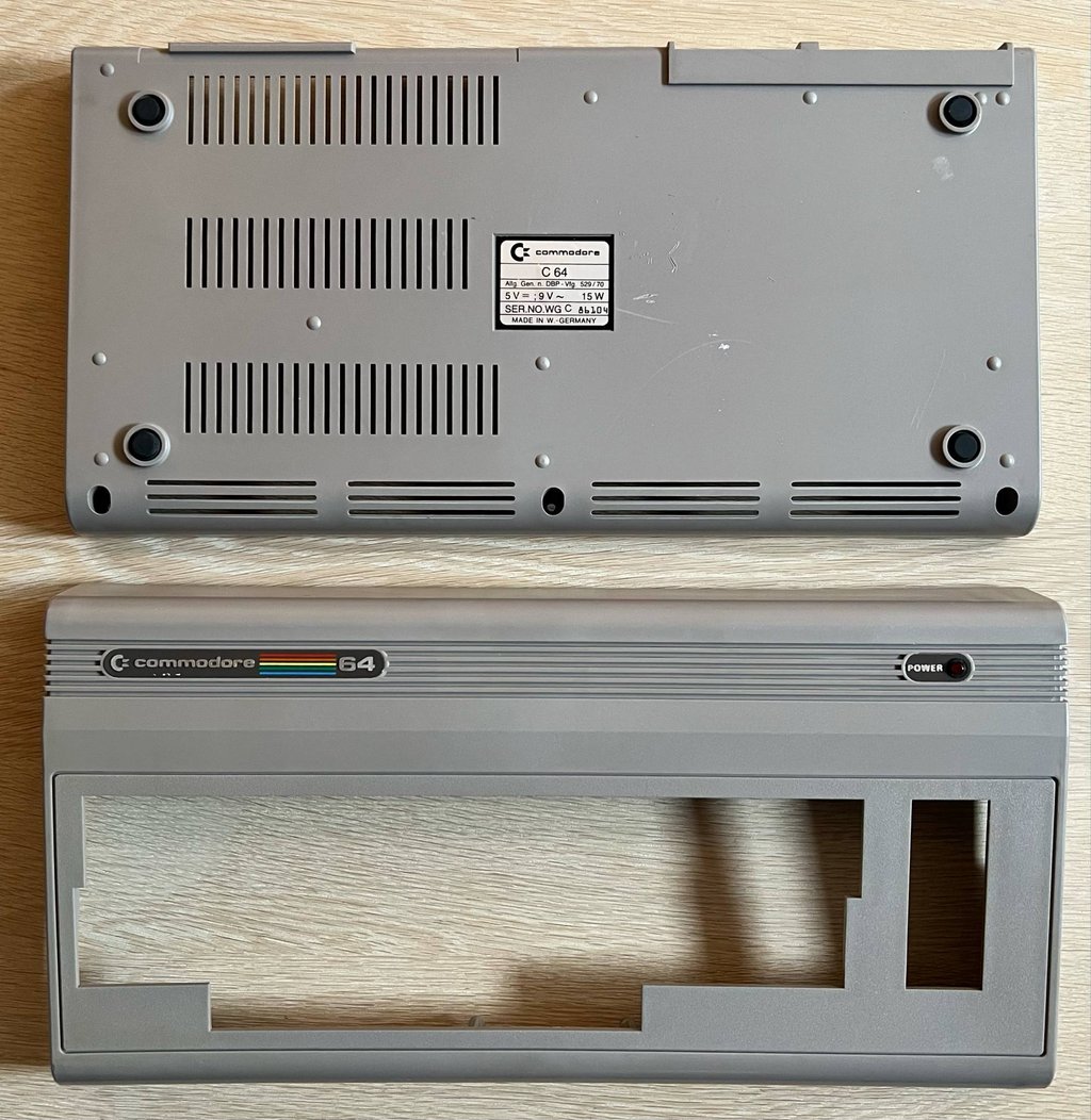
The Commodore 64 breadbin consists of a top- and bottom cover. The first step is to remove the three 3 x 10 mm Phillips screws at the bottom holding the covers together.
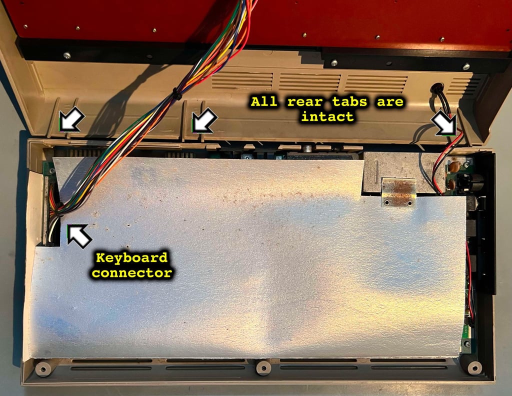
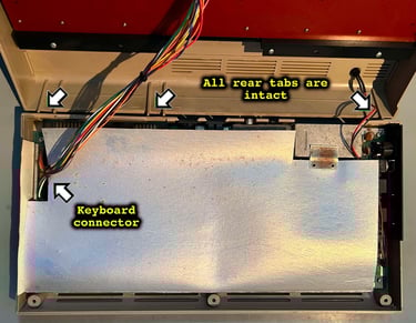
With the screws out of the way the top cover is tilted about 30 degrees, and then carefully lifted from the bottom cover. Now the interior is partly revealed. There are some small signs of dust and moist on the cardboard cover (aka RF-shield), but it does not look bad at all. This machine has rarely been opened before (maybe never?) - the rear tabs are intact! These are super fragile, and they are very likely to break. Another indicator that this machine has rarely been opened, is that the keyboard connector is really hard to remove. It takes quite some (gently) pulling to release it from the PCB.
The RF-shield is pulled away and the PCBA is revealed in all its glory. It is nice to see that the PCBA seems to be in fine condition. There are some areas where dust (and moisture) have gathered near the port openings, but I can not see any corrosion luckily. The datasette port show signs of wear, but this is to be expected. Note that the cardboard RF-shield will not be put back later. This shield has no "real" function in modern time, and will only prevent heat from leaving the interior.
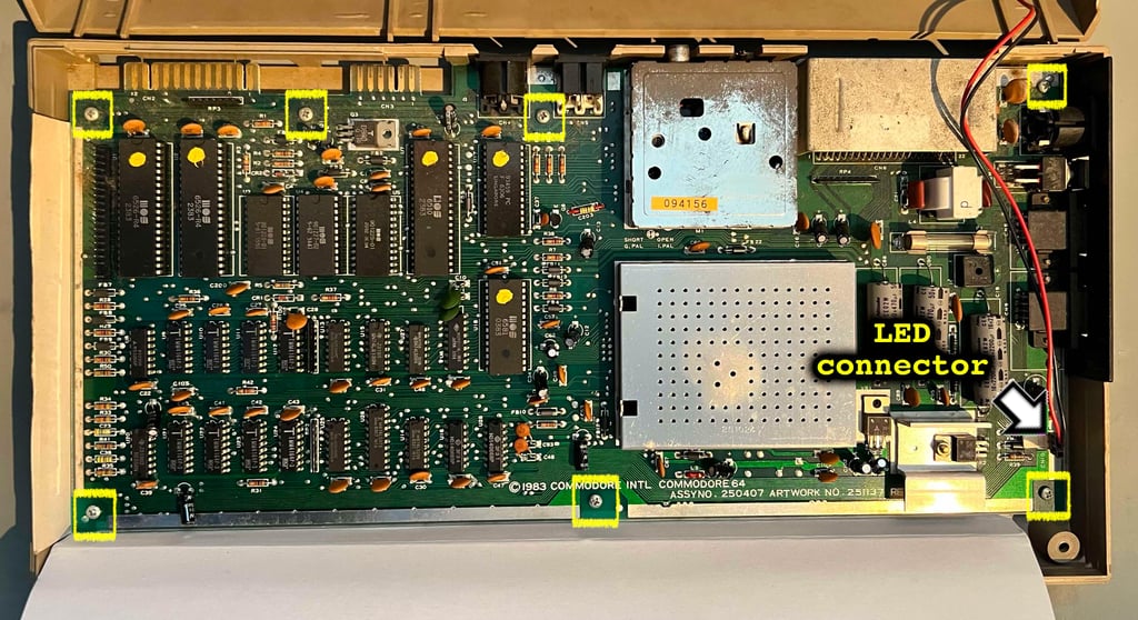

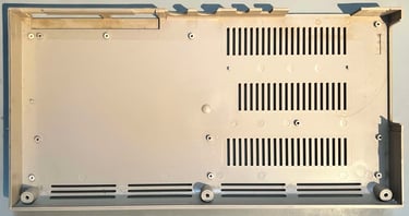
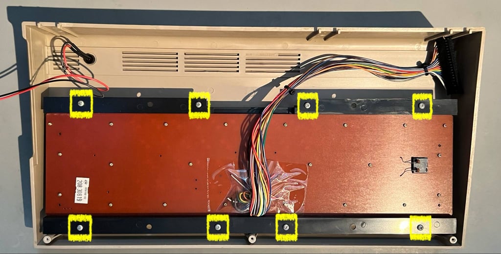
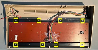
Next, the seven 3 x 7 mm Phillips screws holding the PCB to the back cover and the LED connector are removed. The whole PCB can now be lifted out of the bottom cover. As can be seen from the picture below the bottom cover appear to be intact. No broken stems or clips. There are some signs of dust and grease (and moist) in the rear where the open port holes are located.

Power LED and badges
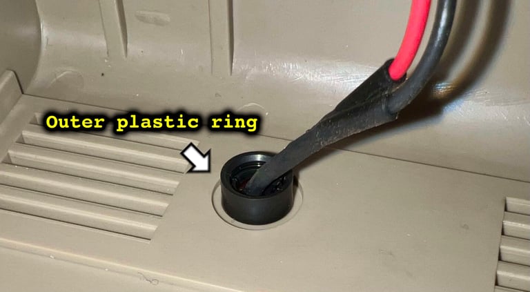
Since the covers are to be cleaned, and retrobrighted, it is good practice to remove both the power LED and the two metal badges on the top cover. This is not very difficult, but it is wise to be careful not to damage these during the process.
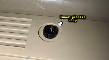
Removing the power LED is done by:
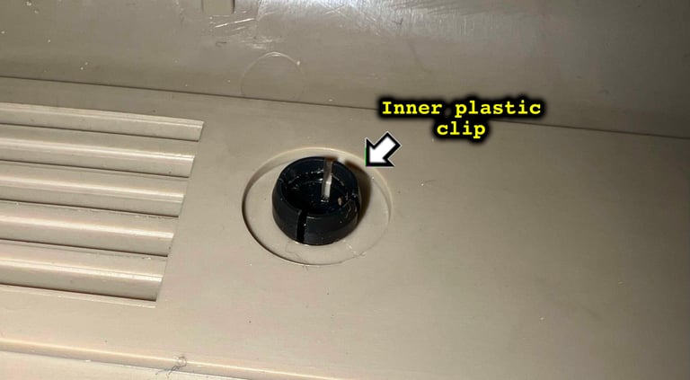
The outer plastic ring is pried off the inner plastic clip with a thin flat screwdriver
Holding, and pressing, the whole front cover with the LED touching the table the LED will "pop-out" with minimal force
With a 5.5 hex nut bolt the inner plastic clip is pushed from the backside of the cover towards the front

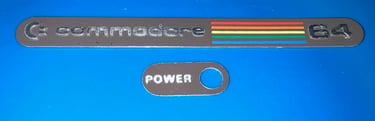
With the LED out of the way, the "POWER" and "commodore 64" badge can be removed. Removing the badges is done by:
The badge is heated with hot air from a hair dryer. This will loosen the grip from the glue holding the badge to the front cover.
Very thin prying tools are used to poke the badge. With great care, and continuously adding hot air, the badge is peeled off without any damage
When the badges are removed they are placed in mild soap water for several days. This will make the glue residue easier to remove (before a new doubled sided tape is applied to the badges).


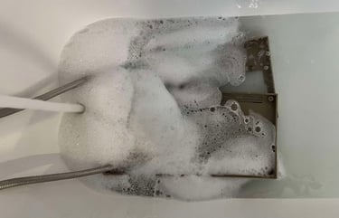
Exterior
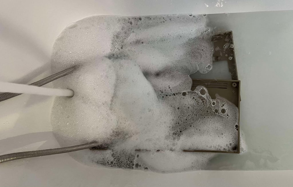
After over 40 years it is to be expected that the covers are quite dirty and yellowed. And this is also the case for this Commodore 64 breadbin. First step to refurbish the top- and bottom covers is to soak the covers in mild soap water for several days. This will dissolve most of the dirt and grime which is sitting the the plastic (especially in the pores). So, first things first: "it´s time to take a long nice bath!".
Spring has finally arrived in Stavanger, Norway. So this is a great opportunity to sunbright the top- and bottom cover. In contrast to what you might think is the case, exposing this old plastic to direct UV (and no chemicals) the plastic will slowly get whiter. Nevertheless, this is a very slow process compared to retrobrighting, but it does help.
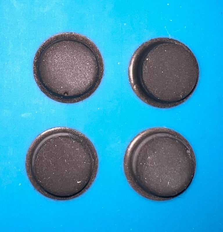
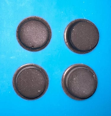
The last remaining spots are removed with isopropanol and a Q-tip. Next, the top- and bottom cover are retrobrighted for approximately 14 hours using 12 % hydrogen peroxide cream applied frequently. Note: before retrorbrighting the bottom cover it is wise to remove the four rubber feet. Otherwise these will become quite "mushy" and sticky.
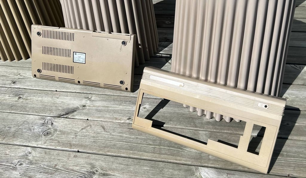
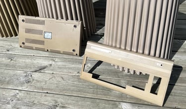
The result from the retrobrighting is very good. Most of the yellowing is gone!

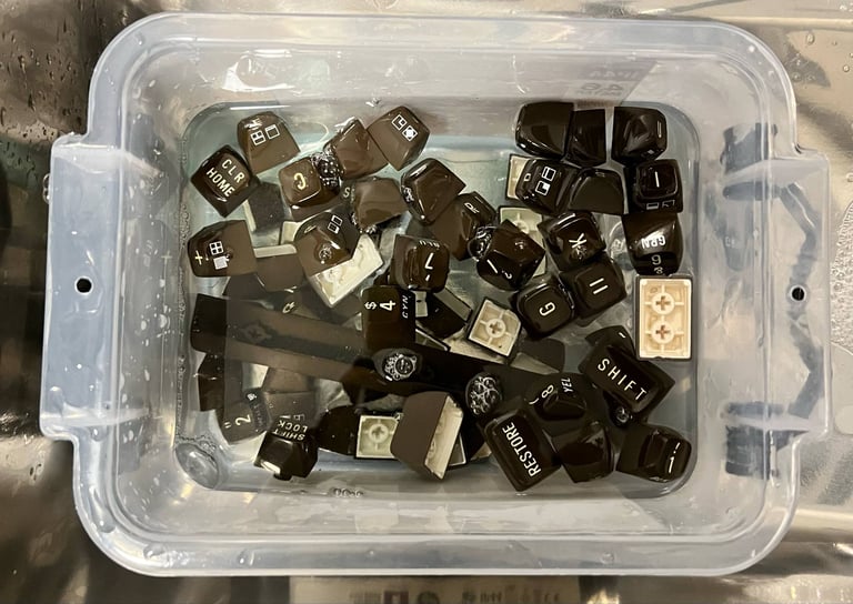
Keyboard
Disassembling the keyboard
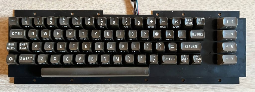
The keyboard is mounted to the top cover with eight 3 x 10 mm Phillips screws. These are removed and the keyboard is lifted from the cover.
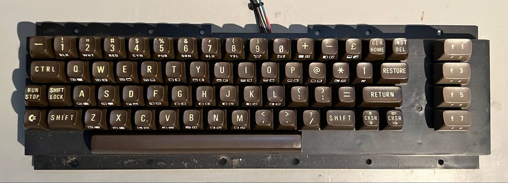
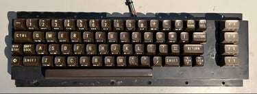
The keyboard is in really good condition. There are some dust and grease beneath the keycaps, and they are quite yellowed, but other than that I can not see or register any damage.
All the keycaps are removed. It is highly recommended to use a special keycap-puller for this operation. This is to reduce the risk of damaging both the keycaps and the plungers below. NOTE: there is a spring beneath each of the keycap. And beneath the spacebar the spring is slightly larger than the rest - so it is good practice to keep this spring separate from the others.
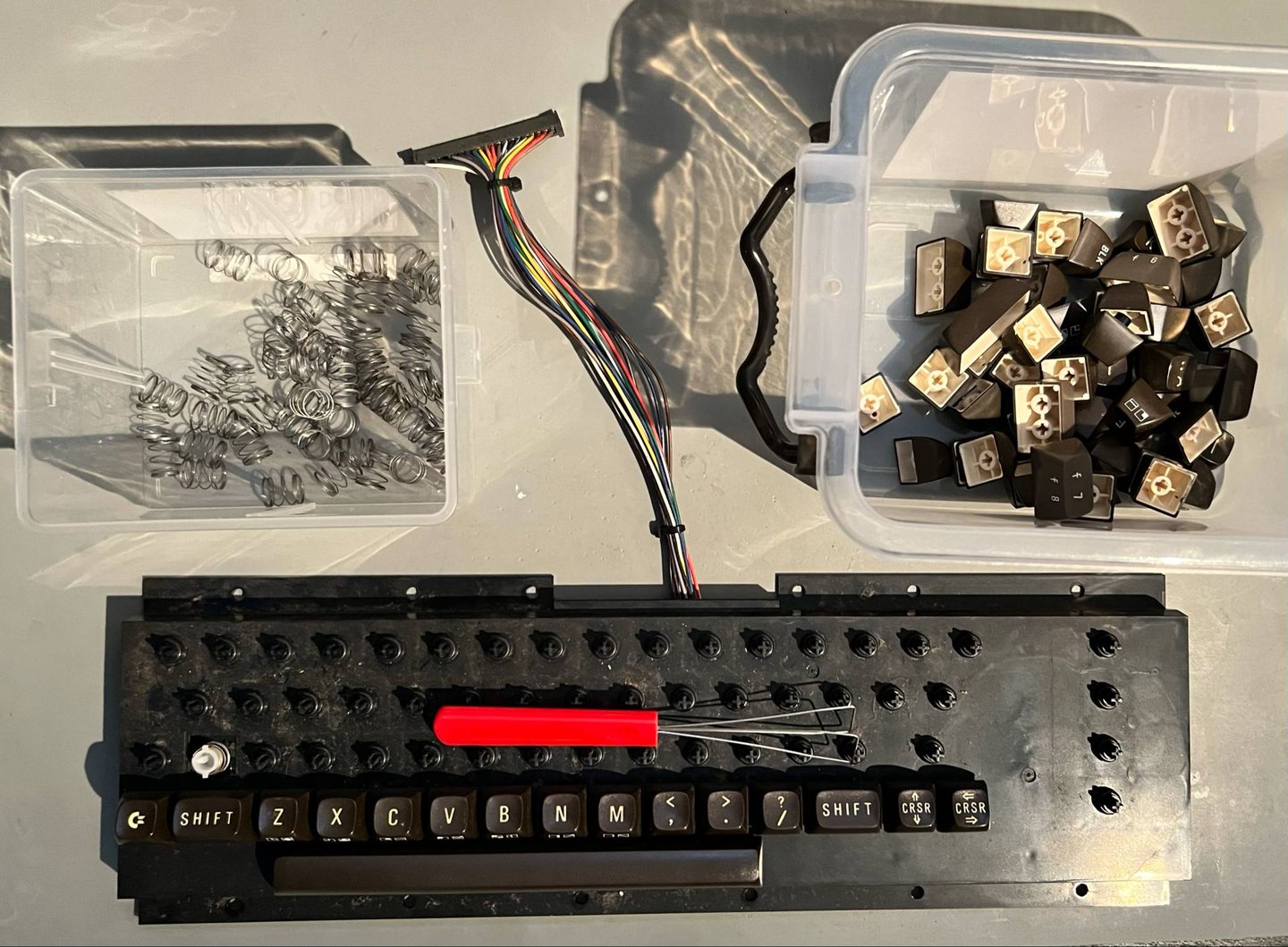
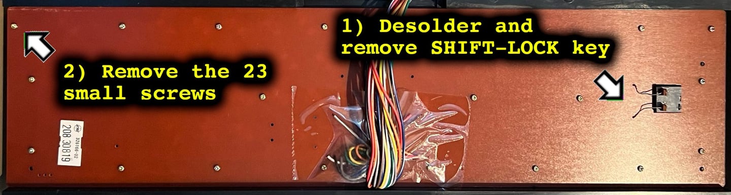
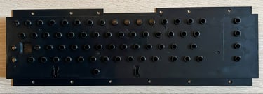
Next, the keyboard is flipped around and the SHIFT-LOCK key is desoldered. There are two uninsulated wires soldered to the back of the key which are desoldered. After desoldering the SHIFT-LOCK key is pushed firmly forward from the backside of the keyboard towards the front. This will make the SHIFT-LOCK key pop-out. Finally, the 23 small screws are removed. The keyboard PCB is now free from the plastic bracket.
Cleaning and refurbishing
When the keycaps are removed they are all placed in a box filled with mild soap water for approximately 72 hours. This will dissolve most of the grease, and prepare the keycaps for retrobright.
To both make the retrobrighting easier, but also make the end result more even, the keycaps are placed on a 3D printed bracket.
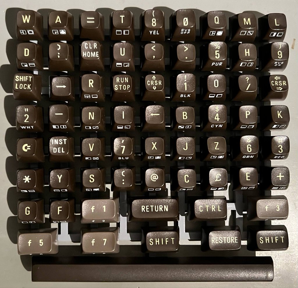
All the keycaps are retrobrighted for 14 hours using 12 % hydrogen peroxide cream applied regularly while exposed to UV. A note and warning: the brown breadbin keycaps will only yellow on the top of the keycap. The symbols on the frontside are printed on the keycaps and will not yellow (as far as I know). The letter on the top of the keycap is not a print, but is in fact the white plastic protruding the top of the keycap. Be warned that the printed symbols on the front are quite fragile. So when doing retrobrighting and cleaning, be very careful not do damage these.
The keyboard plastic frame is cleaned, but not just for the aesthetics. Dust and grease can easily get stuck under the keycaps, and this can lead to contamination of the plungers. And a result the plungers can loose their conductivity. The plastic frame is cleaned with mild soap water. As can be seen from the picture below the frame looks good as new after cleaning.

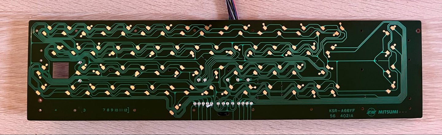
Another sign indicating that this is one of the older revisions of the Commodore 64 is that the keyboard PCB is the "Mitsumi KSR-A66YF 56 4021A". In contrast to the later "B" model, the "A" model is not equipped with carbon pads. Instead the pads are gold (?) plated. From a refurbishing point of view this is beneficial. The gold plated pads can easily be cleaned with isopropanol, and the PCB is basically 100 % as new. In the picture below the keyboard PCB is shown after cleaning.
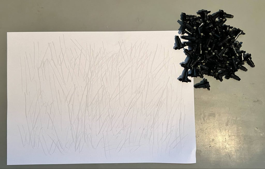
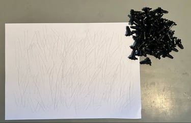
For the keyboard to function flawlessly the plungers needs to work as they should. One very common issue with the Commodore keyboard is that after many (!) years of storage the conductive rubber at the end of each plunger gets contaminated. This contamination will lead to higher resistance in the conductive rubber with the result that key presses will not be registered. It is not advised to clean the plungers with isopropanol unless strictly required as this can deteriorate the conductive rubber. Instead, good practice is to carefully rub the plungers on a clean sheet of paper. This will remove most of the contamination without damaging the plungers.
After retrobrighting the keycaps loos way better. Most of the yellowing is gone. But... unfortunately as mentioned the front symbols on these old brown keycaps are very fragile. And on three of the keycaps the symbols are lost unfortunately. The "6", "8" and "0" lost their symbols, and the "£" lost a bit of the left side symbol. But this is quite normal when working with these old keycaps. Nevertheless, I think the end result is quite good.
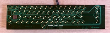
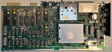
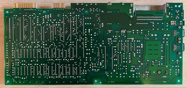
Mainboard
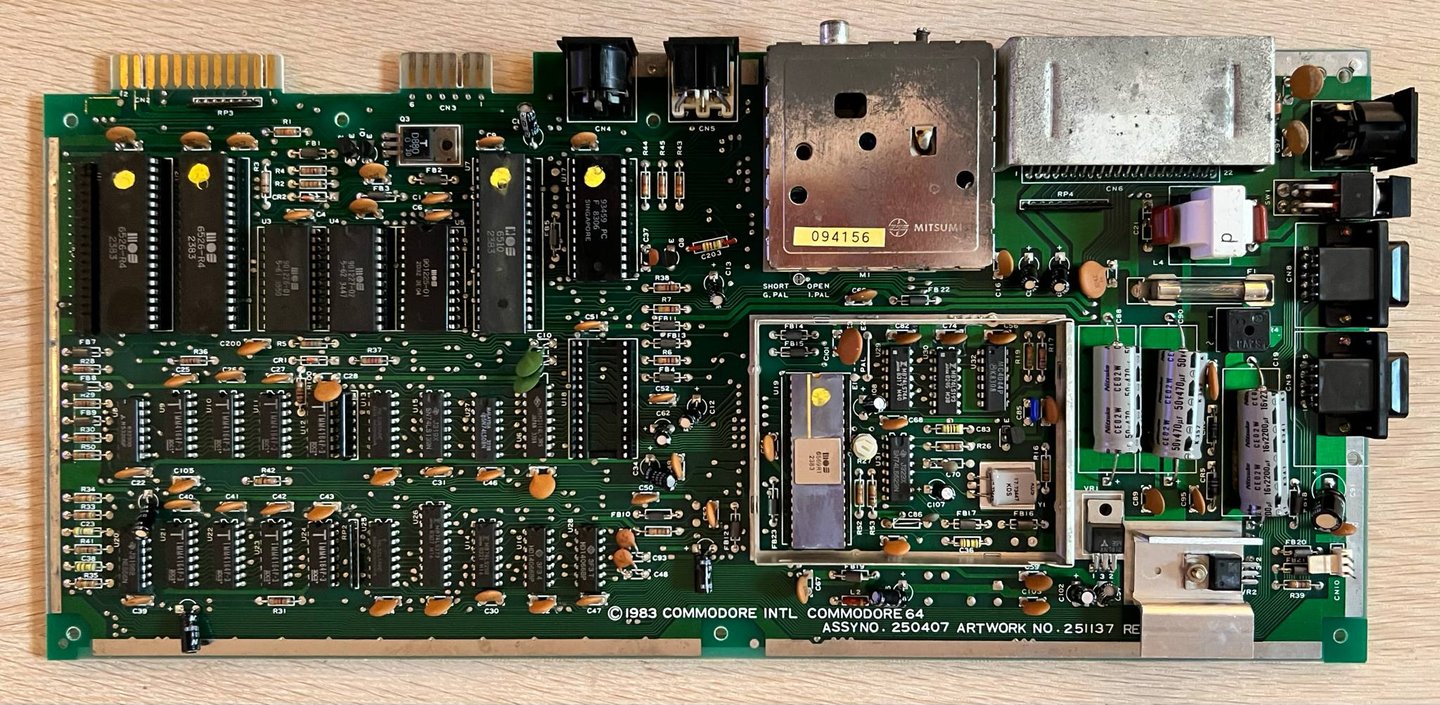
This Commodore 64 is equipped with a mainboard with Assy 250407 / Artwork 251137 (Rev B) which is one of the early version of longboard mainboards. There are some dust and grease in the upper areas, near the user- and datasette port. But otherwise the mainboard looks to be in good condition. Below are some pictures of the mainboard before the refurbish.


Initial testing
Before the refurbishment the mainboard is tested briefly. The goal of this initial testing is to:
Check the audio as it is reported to be non-functioning
Check for any visual disturbance using the RF-signal when outputting the video signal
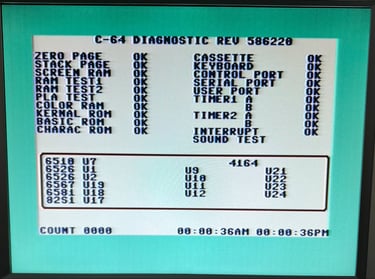
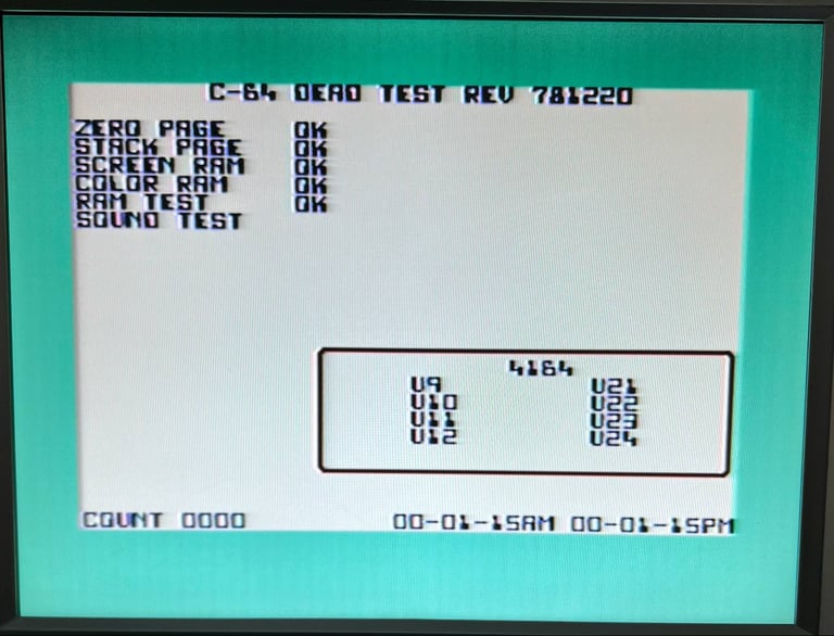
Check for any other faults reported by the Dead Test- and Diagnostics cartridges
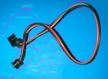
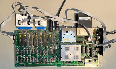
When performing the tests a complete test-harness is used. See picture below. With the test-harness in place on all connectors a complete test can be performed.

Checking the audio
There is obviously something wrong with the audio. The audio, generated by the 6581 SID chip, is not completely silent - but the audio is only partly correct. Some of the voices are very "dim" and/or broken. From the symptoms this points to either a broken SID chip (most likely) or a marginal filter network exterior to the SID chip (less likely). Below are two videos showing how the audio is sounding when both the Dead Test- and Diagnostics cartridge are used.


Checking the RF-output
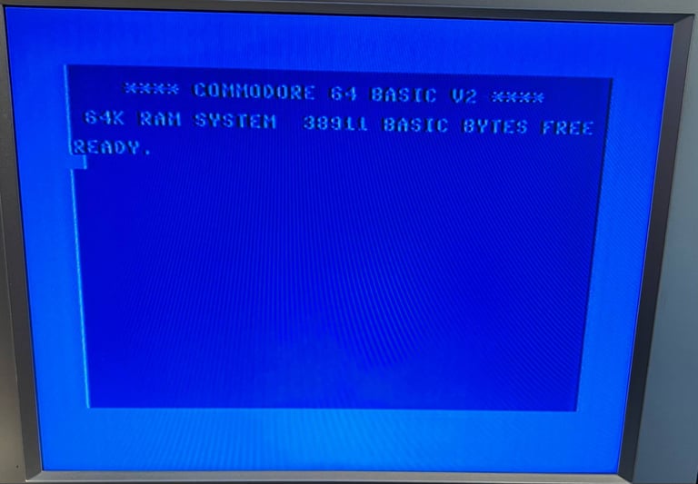
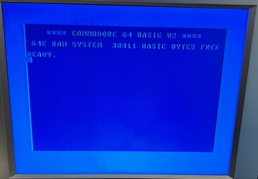
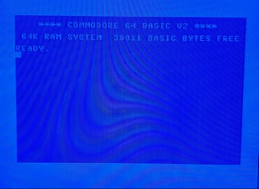
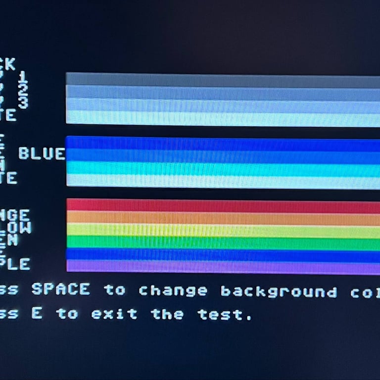
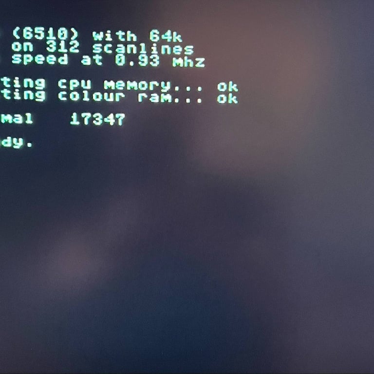
The machine is reported to give a visual disturbance on the video signal (said to give a "double image"). The signal would improve/worsen when wiggling the cable. I am using an old LCD tv with a poor picture quality unfortunately, but I can not find any issue with the RF video output. When wiggling the RF-cable I can not see any visual impact to the video signal. That said, it does not mean that the problem is not there, but I can re-produce the issue currently. Perhaps the issue is more noticeable when outputting other video than the blue boot-up screen. It would be interesting to try the machine with a different RF-cable at the owners premises to see if that makes any difference. Below is a picture of the normal blue boot-up screen when RF-output is used.
Checking for other faults
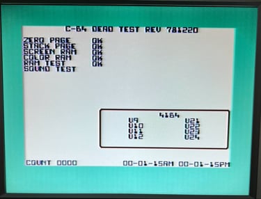
Using the Dead Test- and Diagnostic cartridges the machine is tested for any other faults. None are discovered. All of RAM ICs, CIA, PLA, CPU and all ports report "OK" on all tests.

Visual inspection
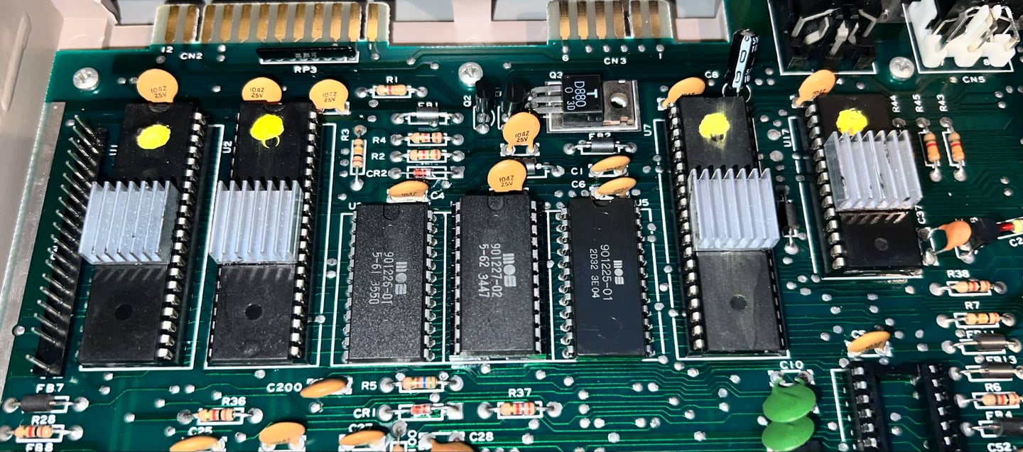
First thing I notice is that there is NO rework done on this board. None! At that is quite impressive since this is one of the early mainboards from Commodore. The assy 250407 / artwork 251137 (Rev B) design is based on the legendary KU-14149HB mainboard (with separate luma and chroma) from 1982. That means that the machine has survived (more or less) over 40 years.
Another interesting thing to notice is that several of the ICs are in sockets. There are different theories why Commodore sometime used sockets and sometimes not on the same mainboard revisions. One theory is that Commodore produced mainboards, but due to lack opp supplies did not have all the custom ICs at the time of production. And this theory seems to hold up with this Commodore 64. In the IC overview further down you can see that many of the custom ICs are produced the first weeks of 1983. But then there is a +20 weeks shift for the custom chips such as MOS 6510 CPU, and the 2 x MOS 6526 CIAs produced all in week 23 of 1983. So, it is a fair guess that this mainboard was actually produced early in the winter of 1983, but with sockets for the CPU, CIA#1 and CIA#2. When summer arrived of 1983 new custom ICs arrived and they were installed - in the already prepared sockets. I can imagine the workers at the factory listening to "Billie Jean" from Michael Jackson at the time released early in 1983!
There are no MOS glue logic on the mainboard which is both a good thing, but also an indicator of an old mainboard. Commodore owning the MOS factory ended up manufacturing their own glue logic (e.g. 74xx logic ICs) to reduce cost. Unfortunately, the quality of this MOS glue logic is known to fail. In this mainboard only quality glue logic ICs are used from well-known vendors. Also, later mainboards usually have MOS branded PLA ICs. In this mainboard the PLA was made by Fairchild (US - California).
Other observations:
No damaged, or bulging, electrolytic capacitors
Signs of wear on the datasette port (needs to be checked)
No signs of corrosion - no obvious damage to tracks or pads
Thermal paste on VIC-II video chip completely dried out (needs to be replenished)
In the table below the custom ICs are listed. As can be seen from the table this machine was probably manufactured (finalised) during summer of 1983.
Checking the voltages
For the Commodore 64 to work flawlessly all the different voltages need to present and within acceptable tolerances. A detailed article on the subject can be found in the HOWTO - Checking the C64 voltages. In the table below all the measures voltages are listed (this list will also be updated after refurbishment). All the required voltages are present and within tolerances, so there are nothing obvious wrong in that area.
Cleaning the mainboard
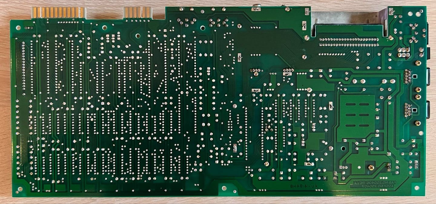
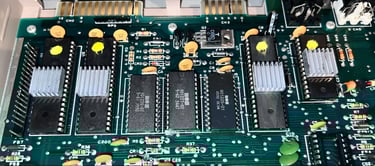
Before the mainboard is cleaned all the socketed chips (and the fuse) are removed from the PCB. The cleaning is done with mild soap water and isopropanol. After the cleaning all the grease and grime is gone. Not only make it the board look really nice, but it also prevents corrosion. Moist can get "stuck" in the dust and grease otherwise. Below are some pictures of the mainboard after cleaning.
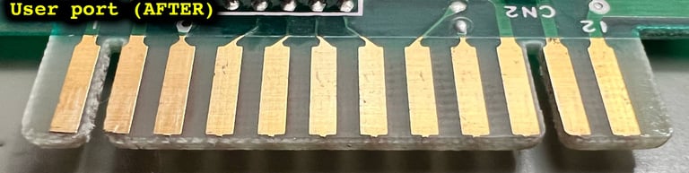
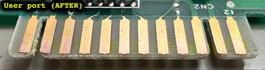
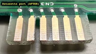
Refurbishing the edge connectors
Both the user port- and the datasette edge connector will be very oxidized after 40+ years. These are gold plated connectors to obtain optimal connection with peripherals (such as the cassette player or modem). But if these are contaminated, and oxidized, the resistance will be higher and could cause issues (such as the notorius "?LOAD ERROR" when loading games from cassette).
It is tempting to use tools such as glass fiber pens to refurbish these, but that is not recommended as it could damage the metal. Instead, a clever way is to use an old school rubber. With the rubber the edge connectors are cleaned from all the grease and oxidation. Finally, the connects are cleaned with isopropanol. Below are some pictures of the process.


Audio - fault investigation and repair
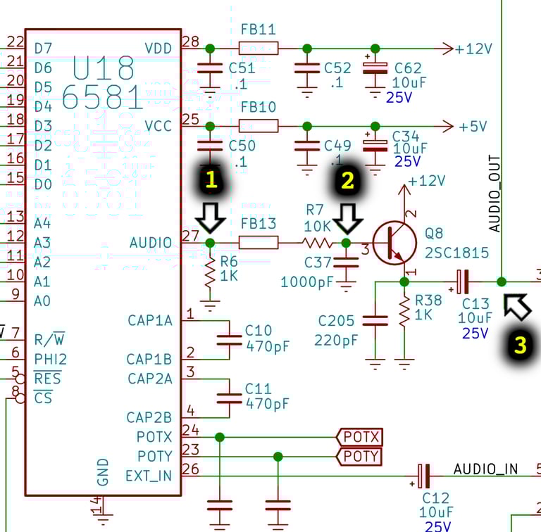
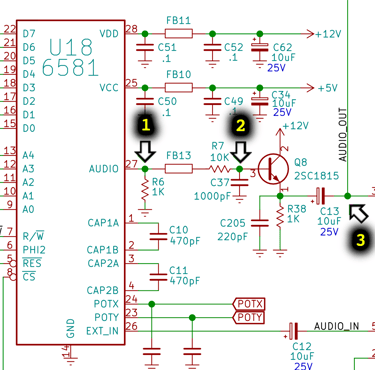
There is obviously something wrong with the audio. The audio is not completely gone, but many (all of the three) sounds both distorted and with too low volume output. Most likely is this caused by a faulty/marginal MOS 6581 analog SID chip. But to make sure this is the case some measurements with the oscilloscope is made.
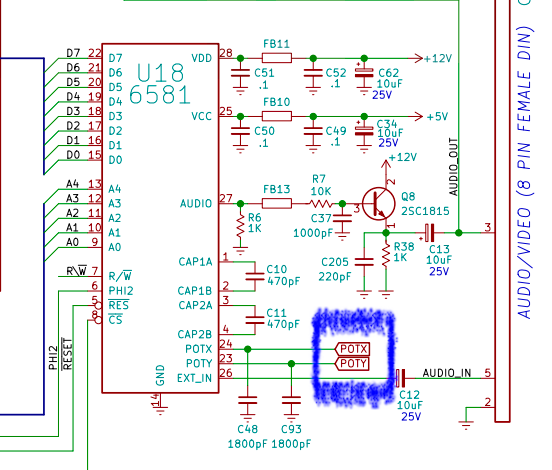
While applying a 1 kHz tone (square or saw) three points are measured (see schematics below):
Pin 27 on the MOS 6581 SID IC. This is the non-amplified output from the chip (1).
Base input on transistor Q8. This is the filtered input to the amplification stage (2).
Negative side on the C13 electrolytic capacitor. This is the amplified, and filtered, signal which is sent to the RF-modulator (3).
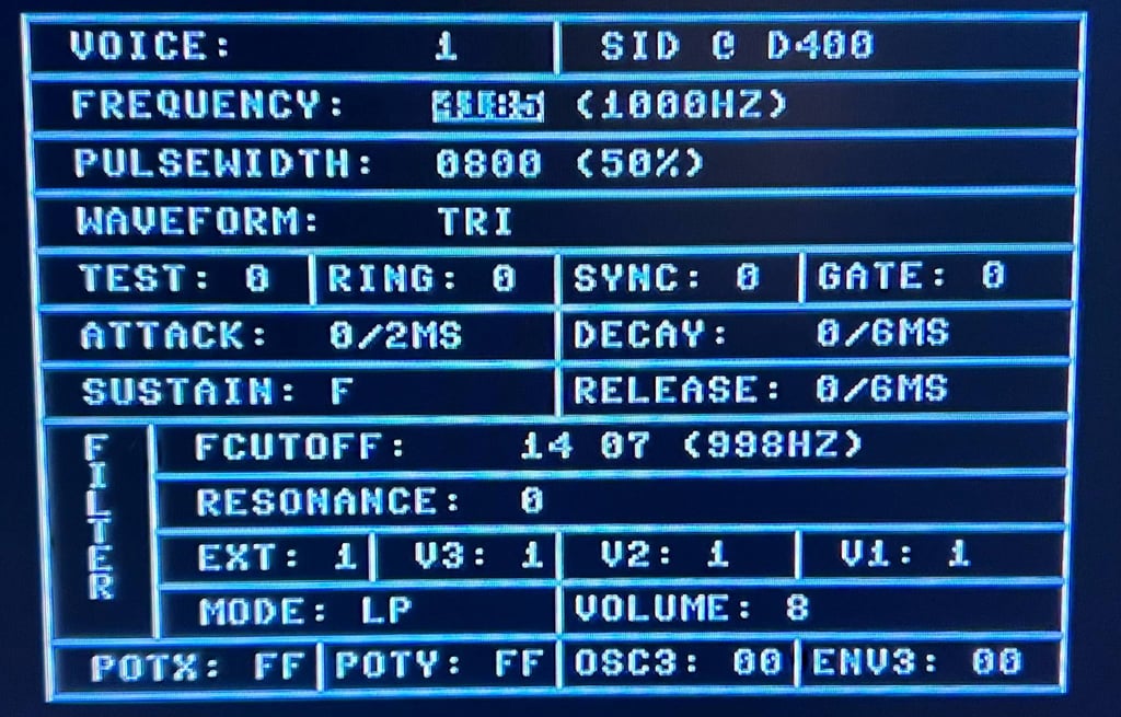
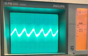
A handy little tool to generate a sound wave is the SIDanalyser v1.0 by Sven Peterson. With this tool a 1 kHz triangular wave is generated, and measured at the dfferent test points for all three voices.
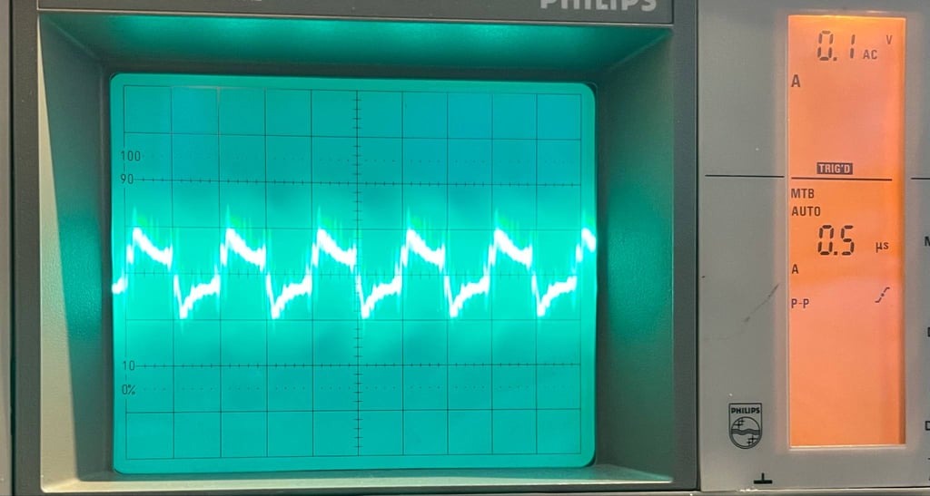
Measuring the 1 kHz triangular wave at test point (1) the fault is easily detectable. Instead of triangular wave, there is a noisy "square-looking" wave. See picture below.

A know-working SID cip (an ARMSID) is installed and the machine is tested. And no surprise, the audio is now working fine and the triangular 1kHz looks as it should. Below is a picture from the testpoint (1) with the known-working SID chip, and a small video clip showing how the audio now sounds.


Adding heat sinks to custom MOS ICs
Heat can reduce the lifespan of the precious custom MOS ICs. And since these are already over 40 years old they are way beyond their expected lifetime. But to reduce the probability of failure for these custom MOS ICs some small heatsinks are added to the 2 x MOS 6526 (CIA), MOS 6510 (CPU) and the FAIRCHILD 93459 (PLA).
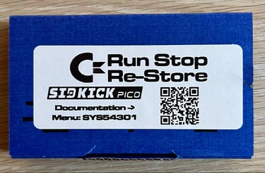
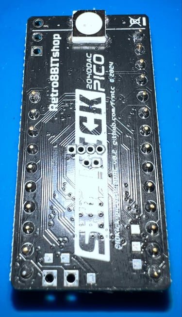
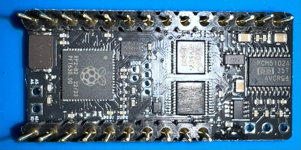
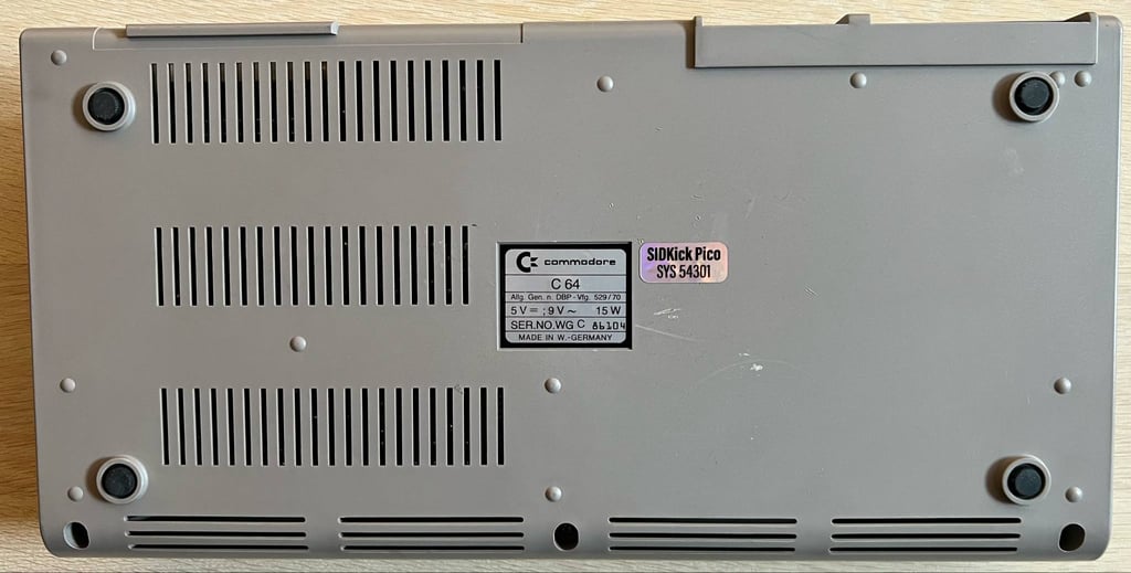
Replacing the SID
The faulty SID is replaced with a new modern variant: the SIDKick Pico ordered from Run Stop Re-Store. This is a drop-in replacement for both the MOS 6581 and MOS 8580 SID chip based on a Raspberry PI Pico. For a detailed overview of the SIDKick Pico, please check the GitHub page from frntc.

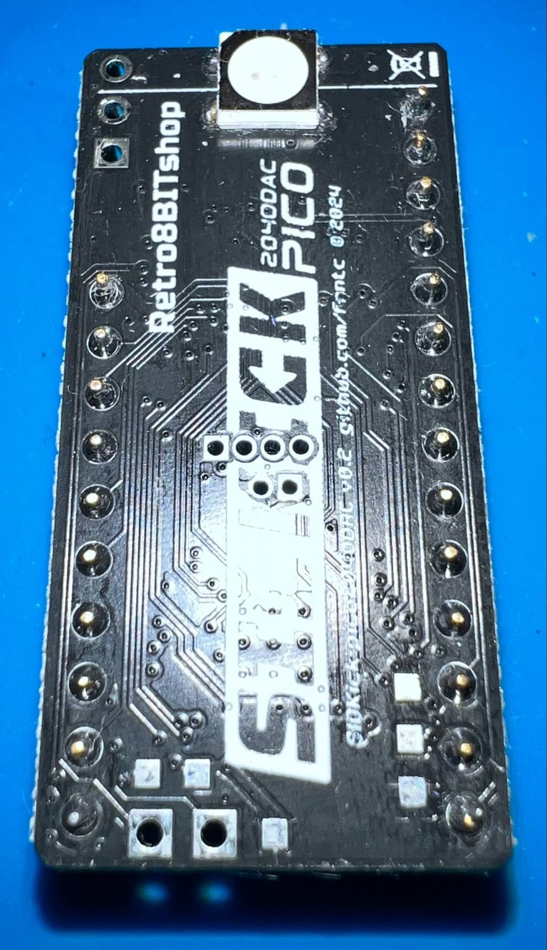

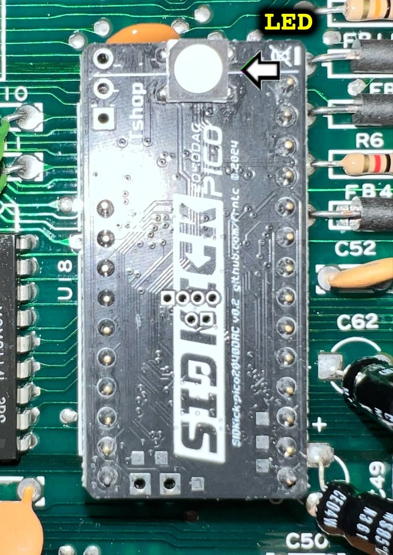
Installing the SIDKick Pico is straightforward by simply placing it in the U18 socket (with some contact cleaner first). Note the orientation to not damage it. It should be installed with the LED pointing towards the rear of the Commodore 64.

Initial testing
Some small testing is done, and they seem to pass fine! The SIDKick Pico is really close to an original SID chip if you ask me (I can not hear any difference). Below are some small videos from the testing. Please note that the audio is not good - that is not due to the SIDKick Pico, but due to a poor recording.


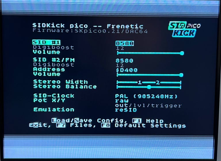
Configuration menu
The SIDKick Pico is a versatile module. Not only will it emulate a SID IC, but you can also choose which version of the chip you want (6581/8580) and adjust several settings. I will not show everything here, but please check out the GitHub page for further details.
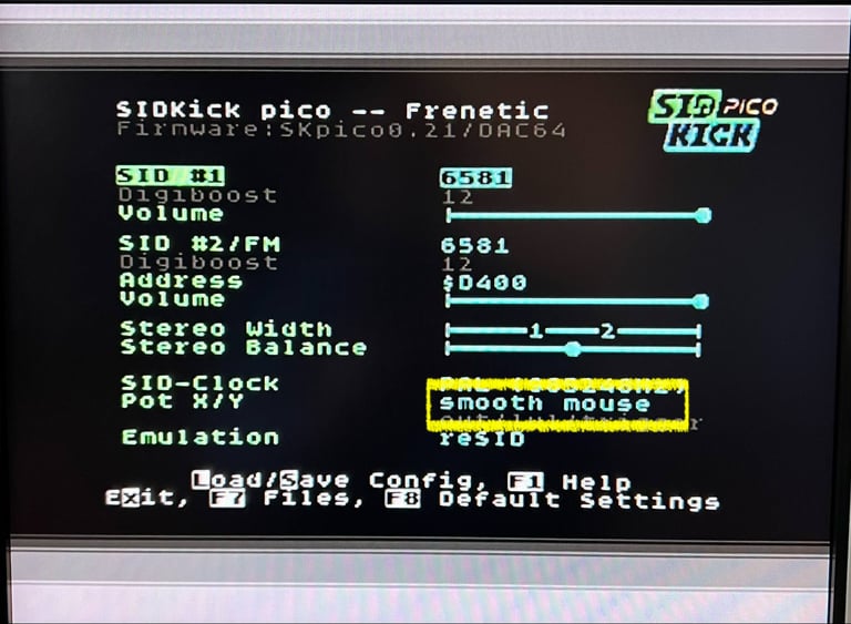
To enter the SIDKick Pico confgiuration menu the command "SYS 54301" is written from the Commodore 64 blue screen. Below is a picture of the default SIDKick Pico configuration menu.

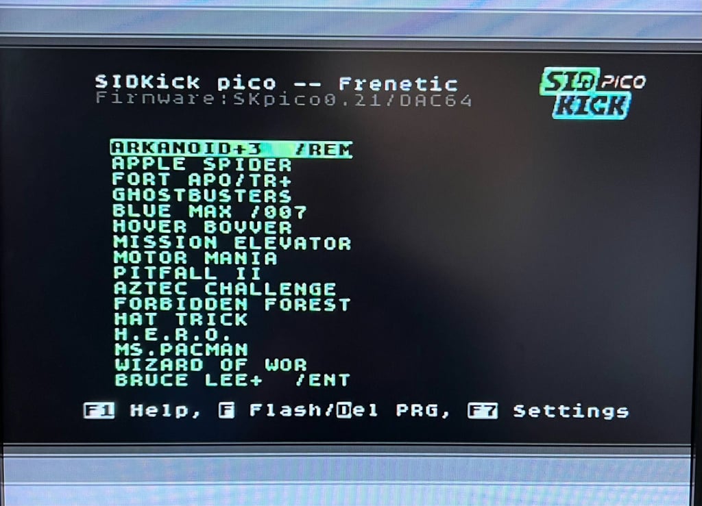
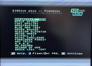
Adding some software
A nice additional feature with the SIDKick Pico is that you can actually run some simple software directly from the chip! Although, this will not work for all software, but some of the (typically the oldest) software will run from the chip.
To access the software you can either go via the configuration menu (SYS 54301), or you can access the software directly by using SYS 54333,X where X references the program for the software list.
Some old classic software is downloaded from CSDB.DK and installed on the SIDKick Pico.
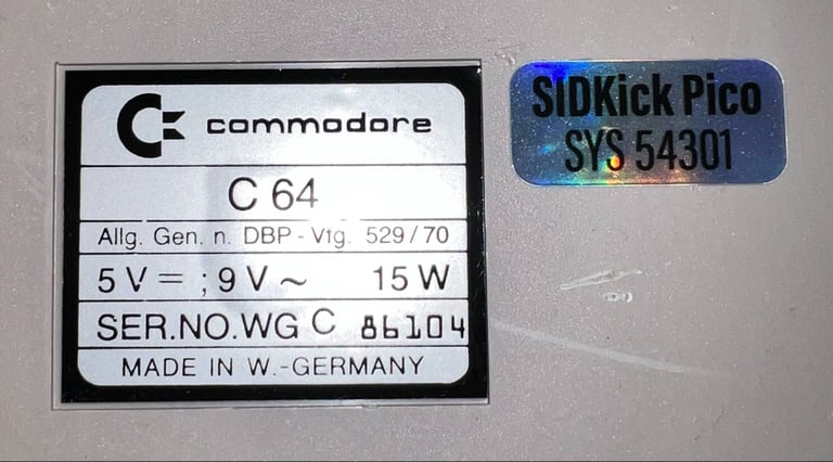
A sticker to remember
A nice little thing with the SIDKick Pico is that a small sticker follows the package. This small sticker says that there is a SIDKick Pico installed, and also the SYS 54301 command to remind the user how to enter the configuration command. This small sticker is placed on the underside of the machine.

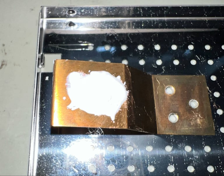
The shield covering the VIC-II is functioning both as a RF-shield and a heatsink. But the thermal paste is long overdue, and completely dried out. Some new thermal paste is added to the shield before it is re-installed on the VIC-II.

Testing
Proof is in the pudding - does it work?
Testing is done through three main stages:
Testing the basic functionality and chips
Testing the complete set of custom ICs and I/O ports
Testing by using the machine playing demos, games etc. accessed by both floppy and datasette to verify correct operation
Basic functionality and chips
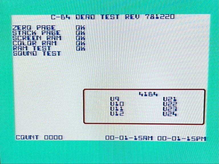
First test is done using the Dead Test Cartridge. This test doesn´t test all the functionality of the Commodore 64, but it does test the basic functionality of the major chips such as the CIA #1/2, CPU, VIC-II, PLA, RAM and SID. As the picture shows below the test is passed.

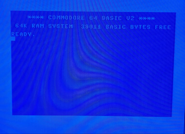
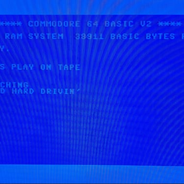
Next test is to power the Commodore 64 to the blue boot up screen and also check the keyboard to make sure all keys works as they should. The test is passed; all keys works and 38911 BASIC Bytes Free.
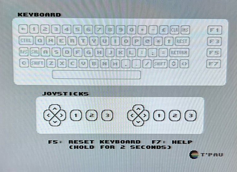
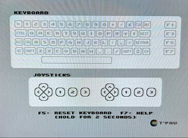
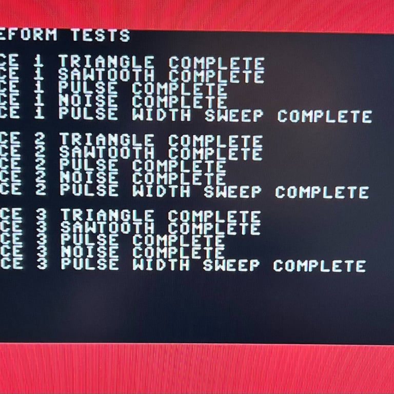
The basic functions of the VIC-II, SID and RAM is tested with 64 Doctor, Commodore 64 SID tester and MemTest64. Note that this is to be considered as basic functionality - more advanced (?) functionality such as sprite handling / collision detection / advanced audio will be tested later. But the basic tests pass without any detected faults (click to enlarge).
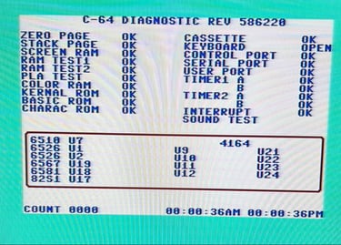
Diagnostics test with harness
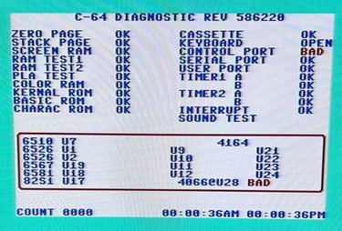
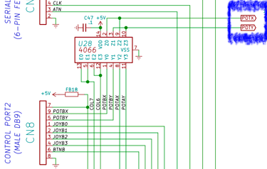
To test all the custom ICs, and I/O ports, the Diagnostics cartridge is used. The Diagnostics cartridge is very valuable when the complete test harness i installed as in "everything" is tested formally. As can be seen from the picture below, two faults (interrelated) issues are identified:
CONTROL PORT reported as BAD
4066 (U28) reported as BAD
But, I think these are "false" alerts caused by the SIDKick Pico. The diagnostics cartridge is using an old software (from back in the 1980s) where new modules were not a thing at all.
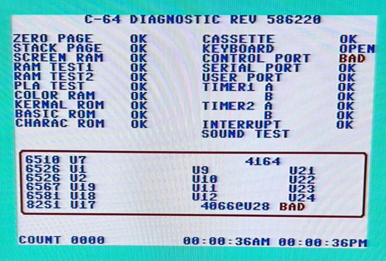
The reason why I think this is a false error is because:
This error is not present when an original SID is used for testing
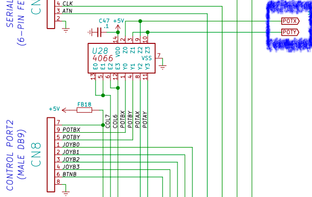
The 4044 (U28) is directly connected to the SID (and now the SIDKick Pico) supplying the POT X/POT Y analog inputs from controller port #2
Below are screenshots from the schematics from the 250407 mainboard showing this relation.
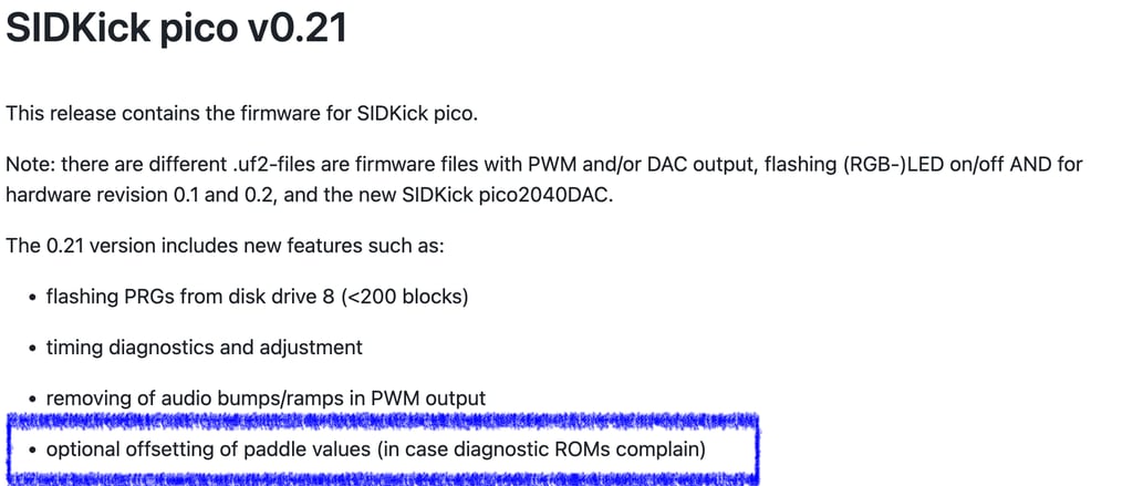
When trying to check for any faults, I noticed something on the GitHub page describing the release notes for the firmware version which is used. It says that it is possible to adjust the paddle values (POT X and POT Y) with the firmware - in case of diagnostics error messages.
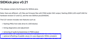
Changing the settings from "RAW" to "Smoot mouse" fixes the problem! With this setting the diagnostics tests pass with flying colours!


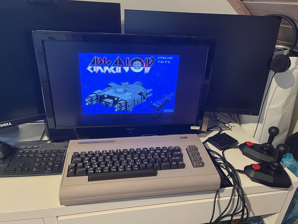
Extended testing
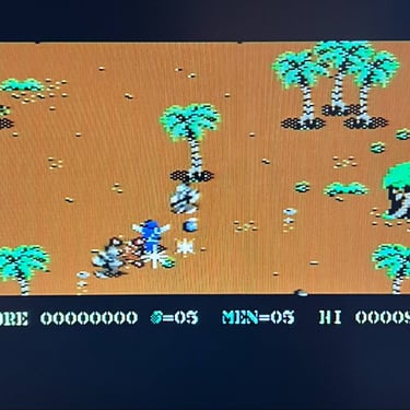
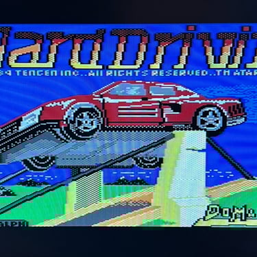
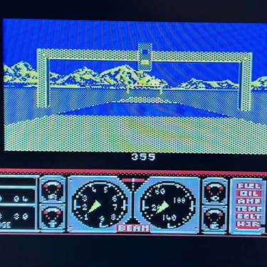
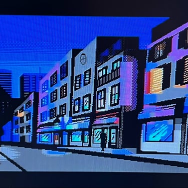
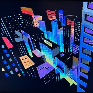
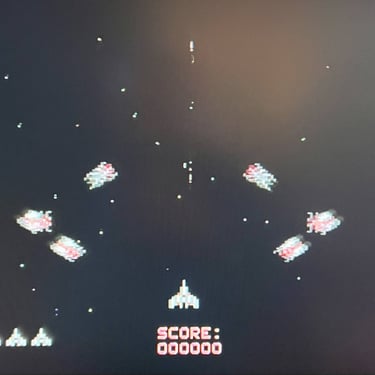
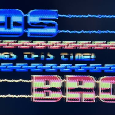
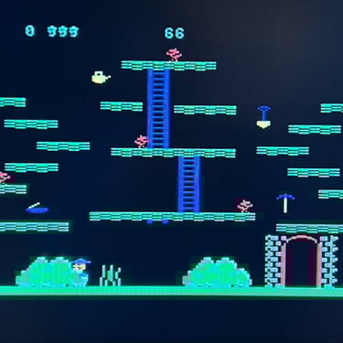
Knowing that the basic functionality of the machine works I continue the testing by using the Commodore 64 for normal operations; playing some games, watching demos, loading from datasette and floppy and using a cartridge. I can not find any issues with this machine. I also pay special attention to the video to make sure that there are no glitches in the graphics - I can´t see any abnormalities. Below is a gallery with pictures from the testing.


Final result
"A picture worth a thousand words"
Below is a collection of the final result from the refurbishment of this C64 breadbin. Hope you like it! Click to enlarge!


"Are you keeping up with the Commodore? 'Cause the Commodore is keepin up with you!"
Below are some pictures of the Commodore 64 back at the customer´s home!

Banner picture credits: Evan-Amos