

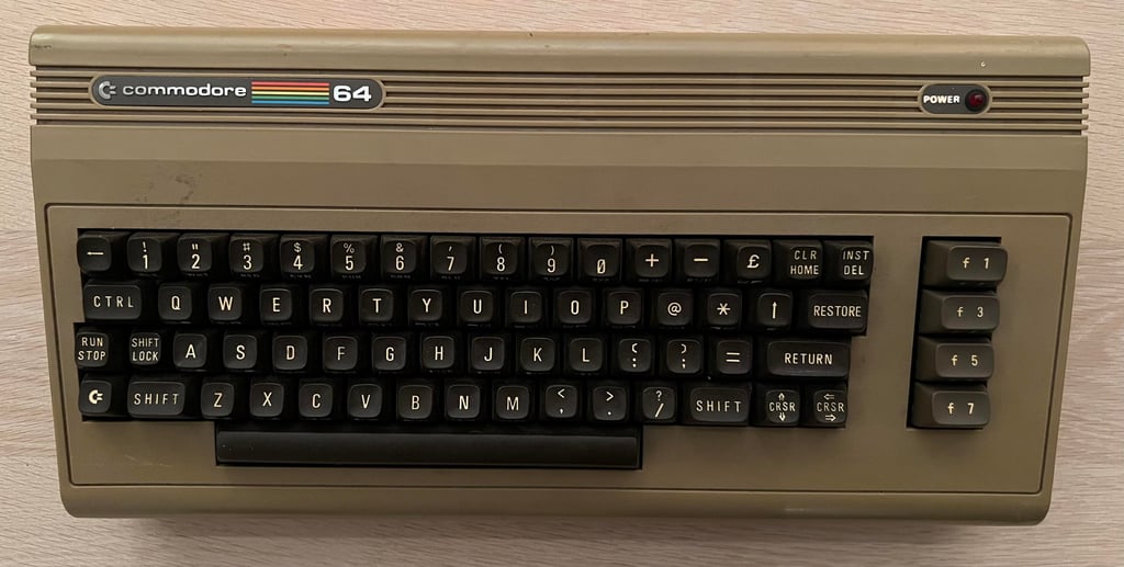
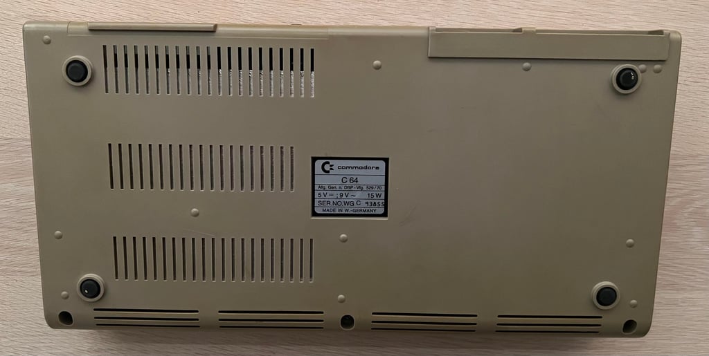
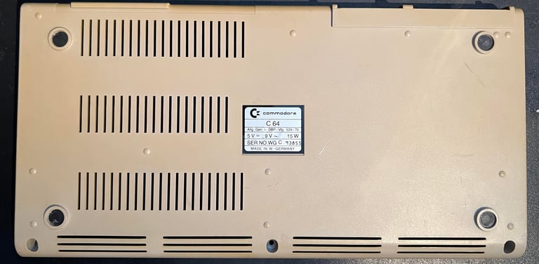
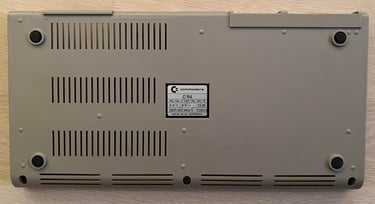
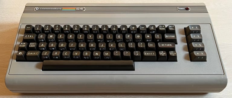
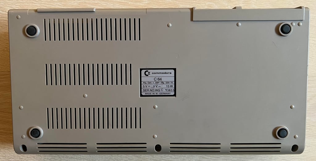
C64 Breadbin [PAL]
Ser. No. 93855
Assy 250407
Artwork 251137 (REV B)
Starting point
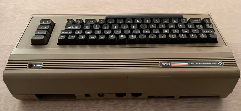
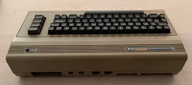
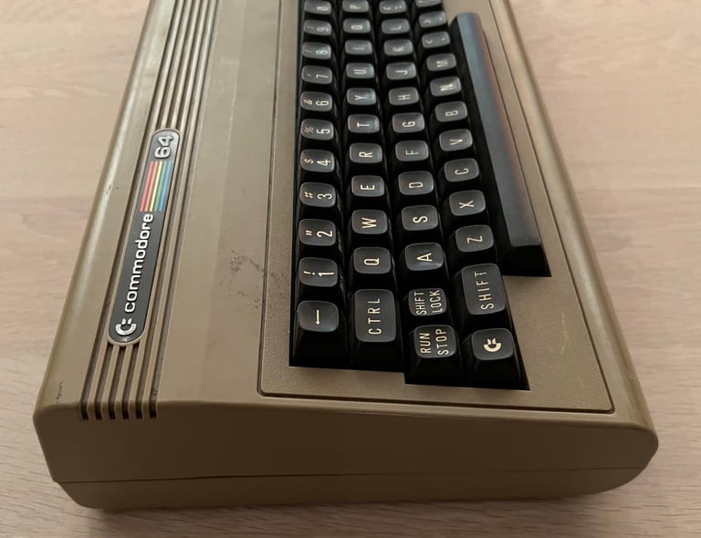
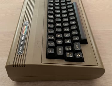
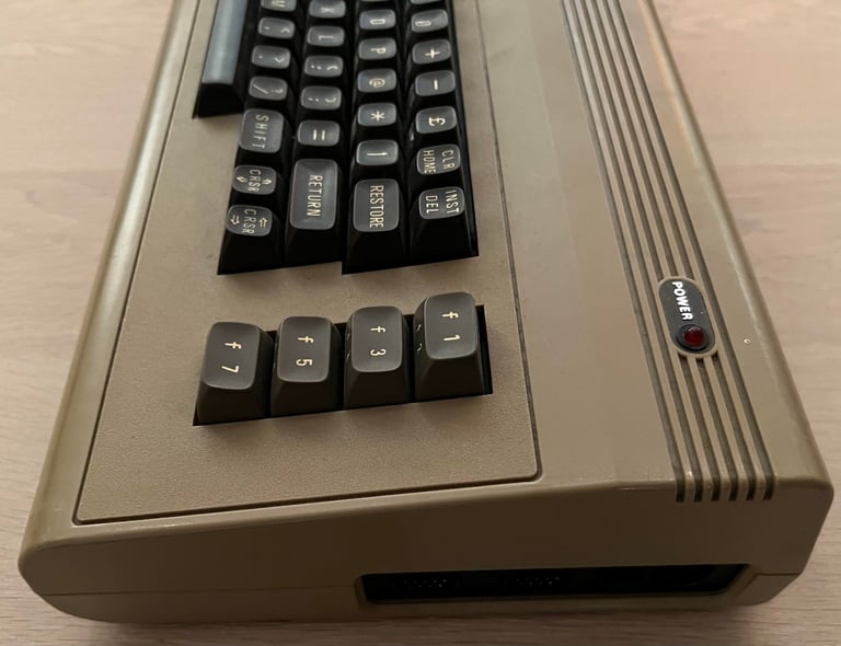
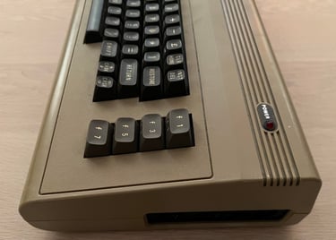
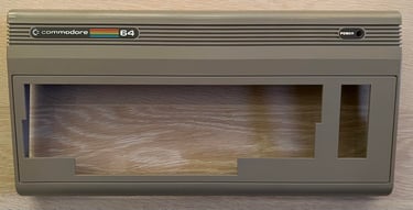
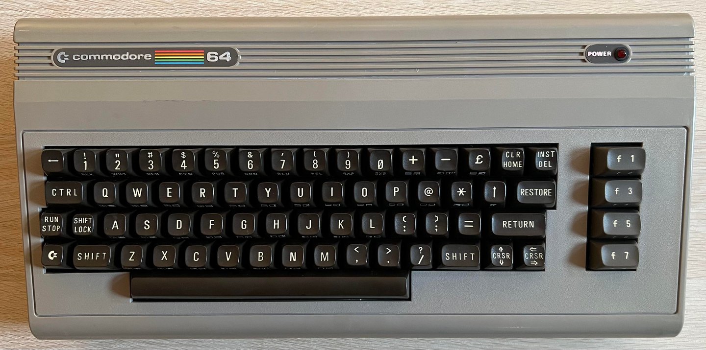
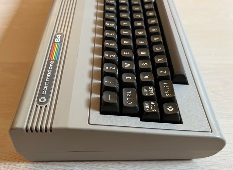
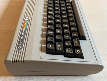
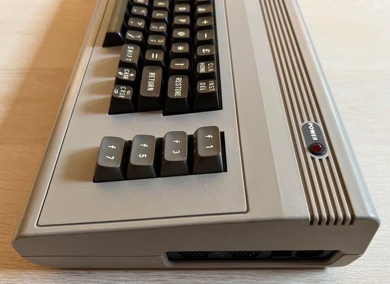
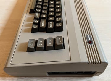
The machine looks to be in quite good condition. Nice! The whole chassis and different parts appear to be intact. It is incredibly dirty, covered with dirt and grease (pictures doesn´t do it justice - it is actually worse than the pictures shows). There are some cable "burn" marks on the bottom cover and the "Commodore 64" badge is partially loose. All the keys and connectors appears to be ok, but time will show. The casing is rather yellowed so some retrobrighting is required.
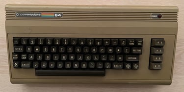
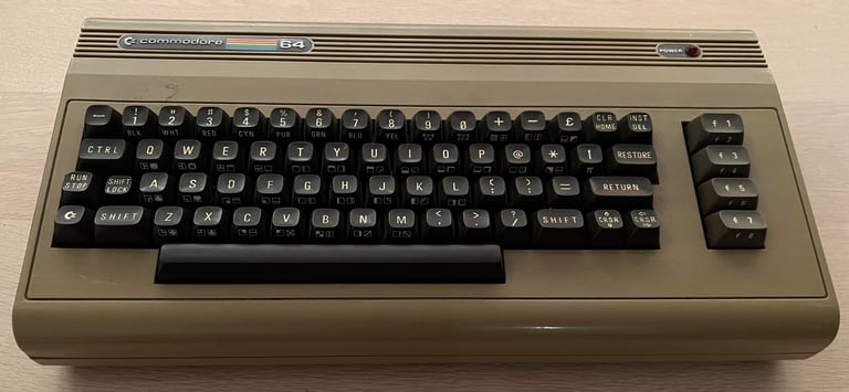
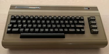
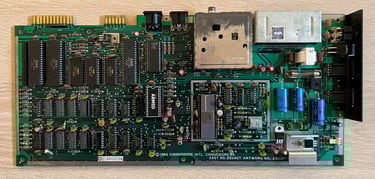
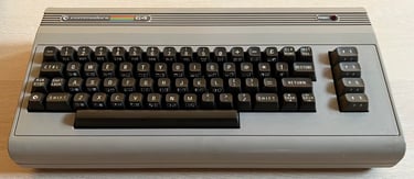
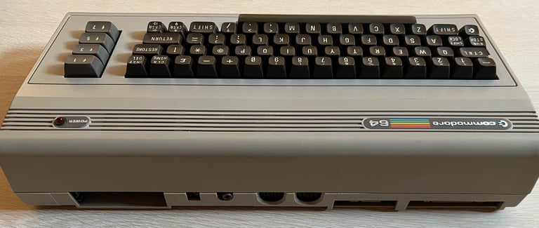
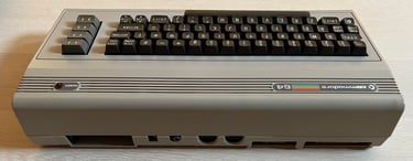
I have no idea if this machine works or not before refurbishment. Below are some pictures of the machine before refurbishment.
Refurbishment plan
The refurbishment plan for this C64 breadbin (several of them in parallell):
- Refurbish the casing (cleaning, repairing and retrobrighting)
- Refurbish the keyboard (cleaning and reviving the plungers)
- Refurbish main board (cleaning, checking, repairing, replacing capacitors and voltage regulators, adding heat sinks etc.)
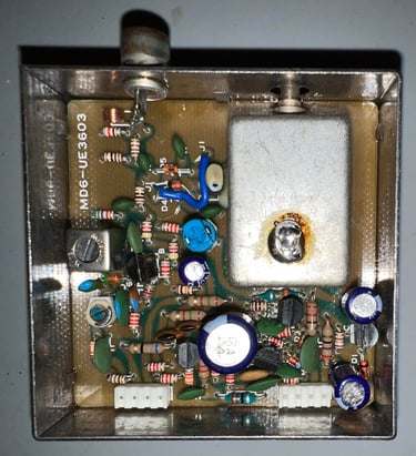
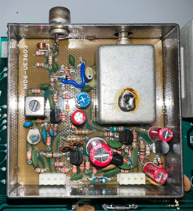
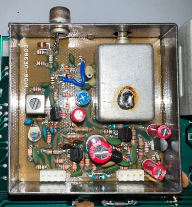
- Recap RF-modulator
- Verify operation by testing
The plan can be updated during the refurbishment process. Sometimes I discover areas that needs special attention.
Opens it up...
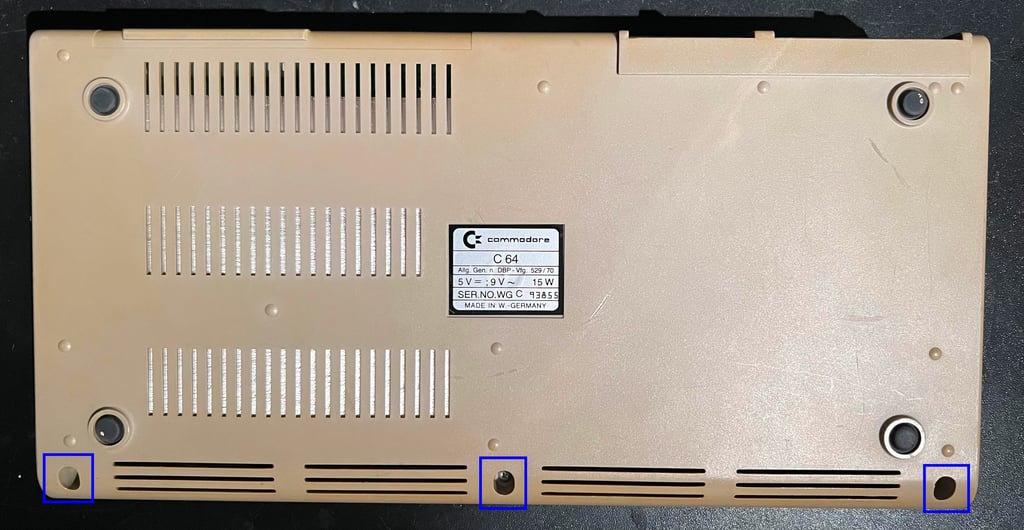
The top- and bottom cover are held together by rear clips and three screws. The three screws located at the bottom cover are removed first (blue squares).

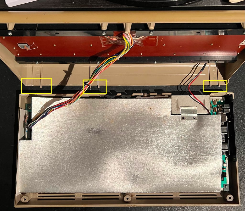
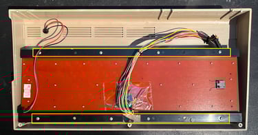
Top cover is lifted about 30 degrees and then carefully wiggled from the bottom cover. The rear clips are super brittle and are usually broken (or break during wiggling). As is the case here. Many of the rear clips are ok (see yellow squares), but new 3D printed clips will be added later. With the top cover out of the way, the first sight of the interior is exposed. There are sign of dirt and dust, but the RF shields is in very good condition. So there has probably not been any moist inside here while being stored.

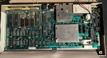
Next, the RF shield, the keyboard connector and the LED connector are removed. Now the PCB is revealed in all its glory - and it looks very good! Upper half of the PCB is full of dust, but lower half looks as new.

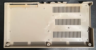
The seven screws are removed from the PCB, and now the PCB can be lifted away from the bottom cover. The cardboard RF shield is discarded. This shield no longer have any practical value - it only traps the heat and could reduce the longevity of the ICs. The bottom cover appears to be in good condition. Only some dirt and grease, but otherwise no damage.

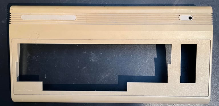
Exterior casing
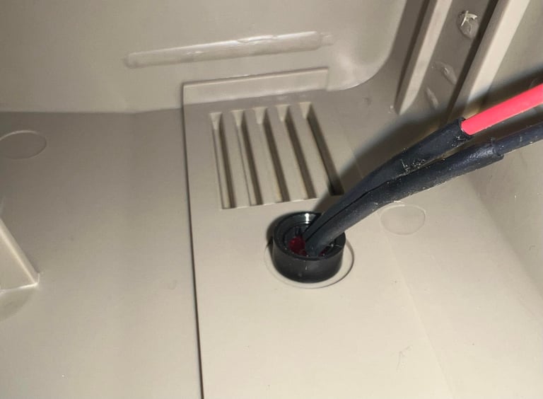
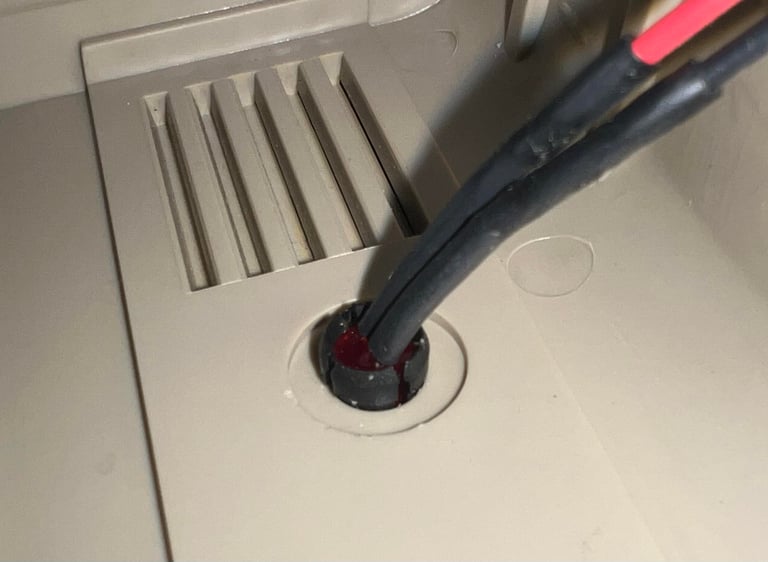
Both the top- and bottom cover are dirty and yellowed. Before the covers are soaked in mild soap water the metal badges, rubber feets and the LED are removed. First the LED is removed which is easily done by following these steps:
The plastic clip on the inside is removed with a thin flat screw driver
The LED is pressed firmly from the outside towards the inside. This will make the LED pop out of the plastic holder
The empty plastic holder is squeezed at the rear and then pressed firmly from the inside towards the outside
Below are some pictures from the process.
The metal badges are carefully removed by using some hot air from a hair dryer while at the same time prying the badges with a small flat screwdriver. Also, the rubber feets are removed with a flat screwdriver (these are just glued with some double sided tape).
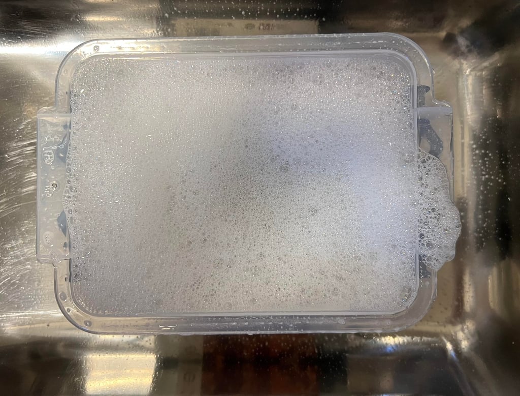
Below are some pictures of the top- and bottom cover before cleaning and retrobrighting.

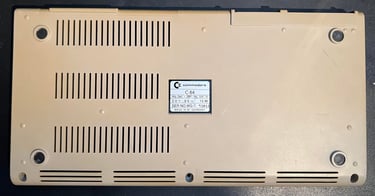
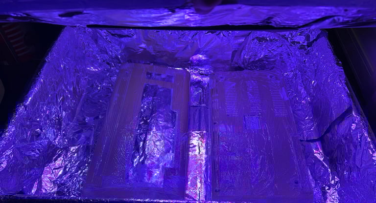
The covers are so dirty that it requires 2 x 24 hours of mild soap bath. And then cleaning the remaining spots with isopropanol. Finally, the covers are retrobrighted for about 12 hours using 12 % hydroperoxide cream which is replenish frequently. Below are pictures from after cleaning and when the covers are in the UV chambers for some retrobrighting.


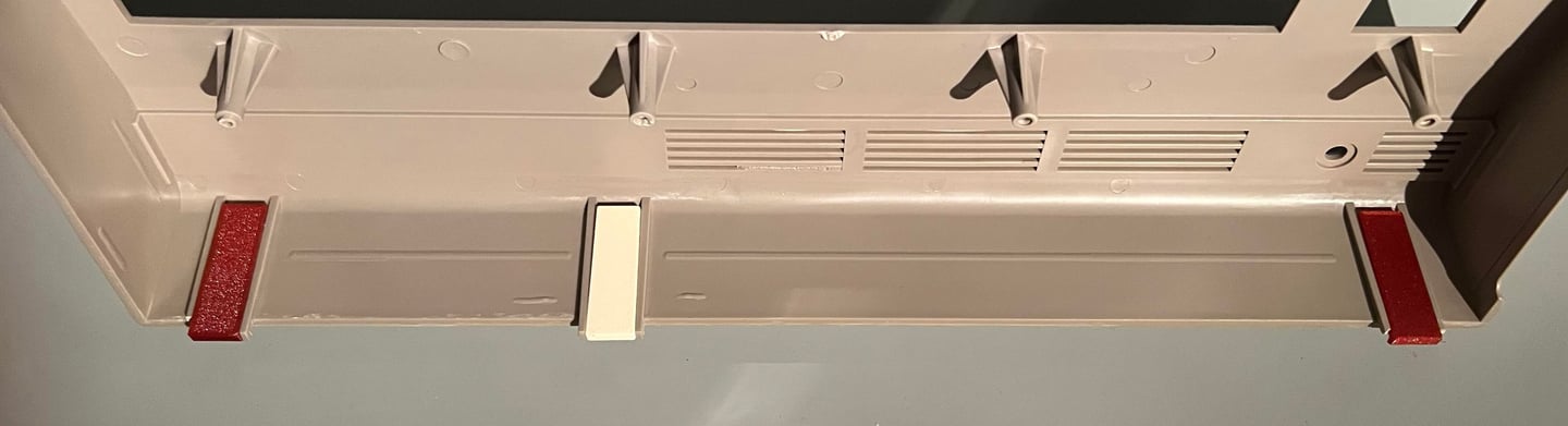
Some of the rear plastic tabs are damaged. The function of these tabs are to keep the rear of both covers together. Luckily, it is possible to 3D print some replacement parts which works very well (even better than the original). I use these for refurbishment: https://www.thingiverse.com/thing:5916458
Below is a picture of the new 3D printed parts glued in place.
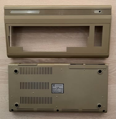
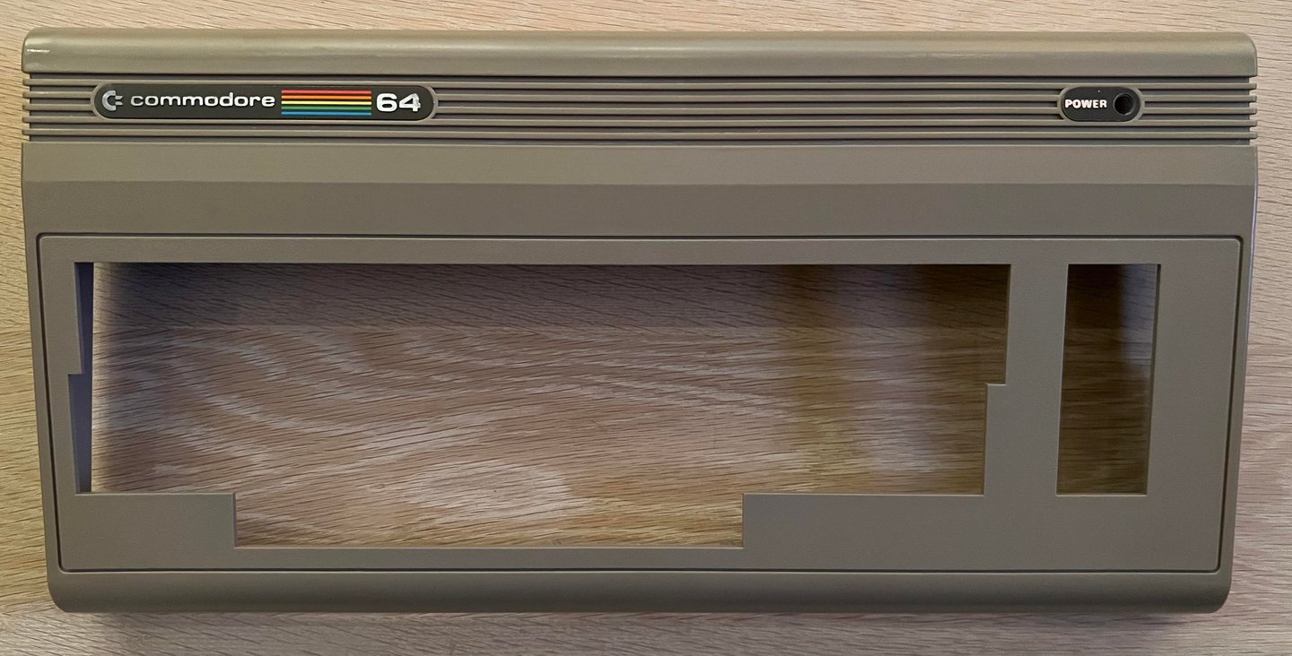
The result of the retrobrighting appears to be quite good. The yellowing is no longer so dominating! Below are some pictures after retrobright.

Keyboard
A detailed general article on how to refurbish a Commodore 64 keyboard can be found here. The keyboard is loosened from the top cover by removing the eight screws. It is important to be careful when removing these to reduce the risk of breaking the plastic stems holding the keyboard. See yellow squares.

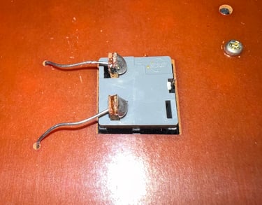
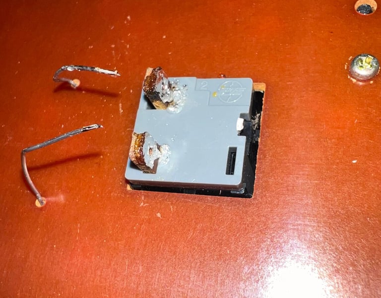
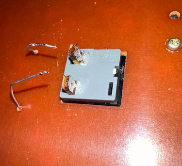
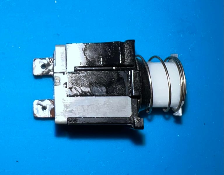
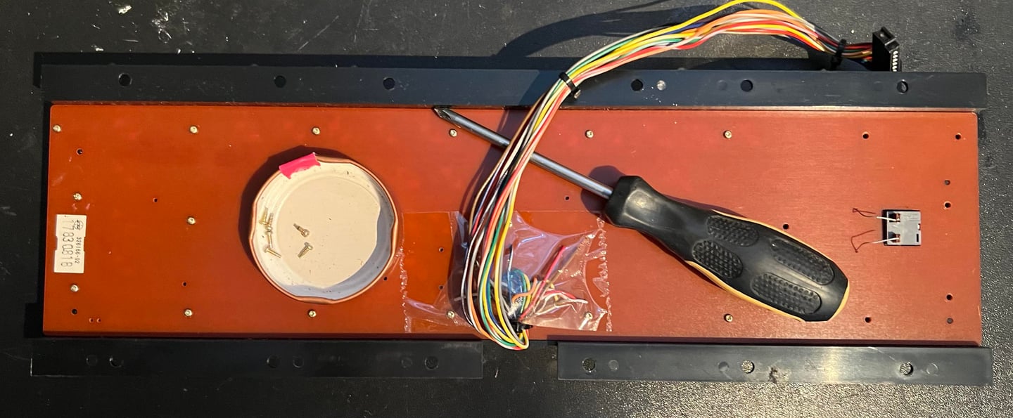
The two wires attached to the SHIFT-LOCK key are desoldered. The the SHIFT-LOCK key is pushed from the backside of the keyboard towards the front. This will make the key pop out with minimal force. The SHIFT-LOCK key is tested with a multimeter for continuity and cleaned with isopropanol.


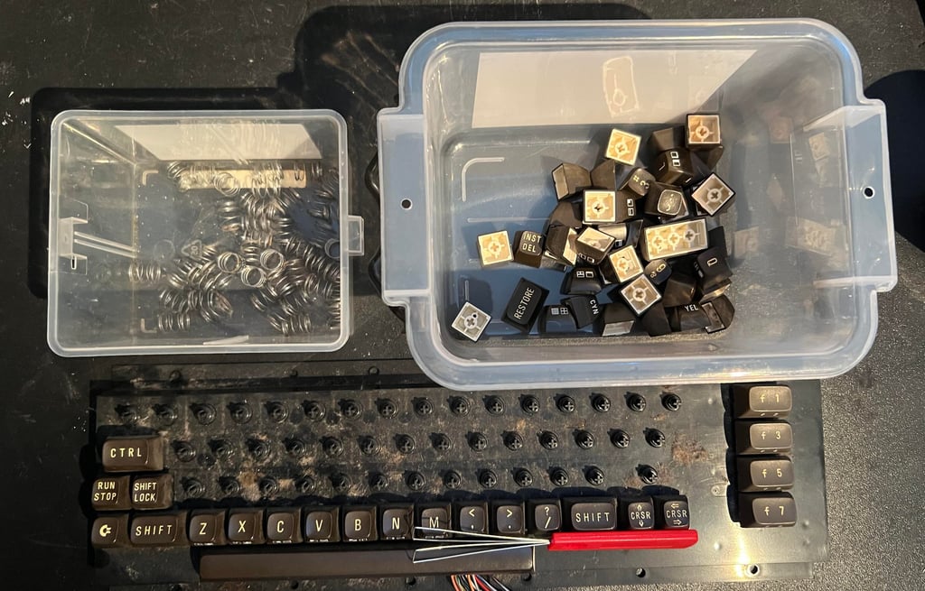
All the keys are carefully removed using the keycap puller - no plungers were damaged. Note that there is a small spring beneath each keycap, and there is a special (larger) spring beneath the SPACE bar. As can be seen from the picture below there is a lot of grease and dirt under the keys. But this is to be expected after almost 40 years.

The keycaps are soaked in mild soap water, with some glass cleaning spray, for about 48 hours. This will dissolve most of the old grease and fat from the keys.
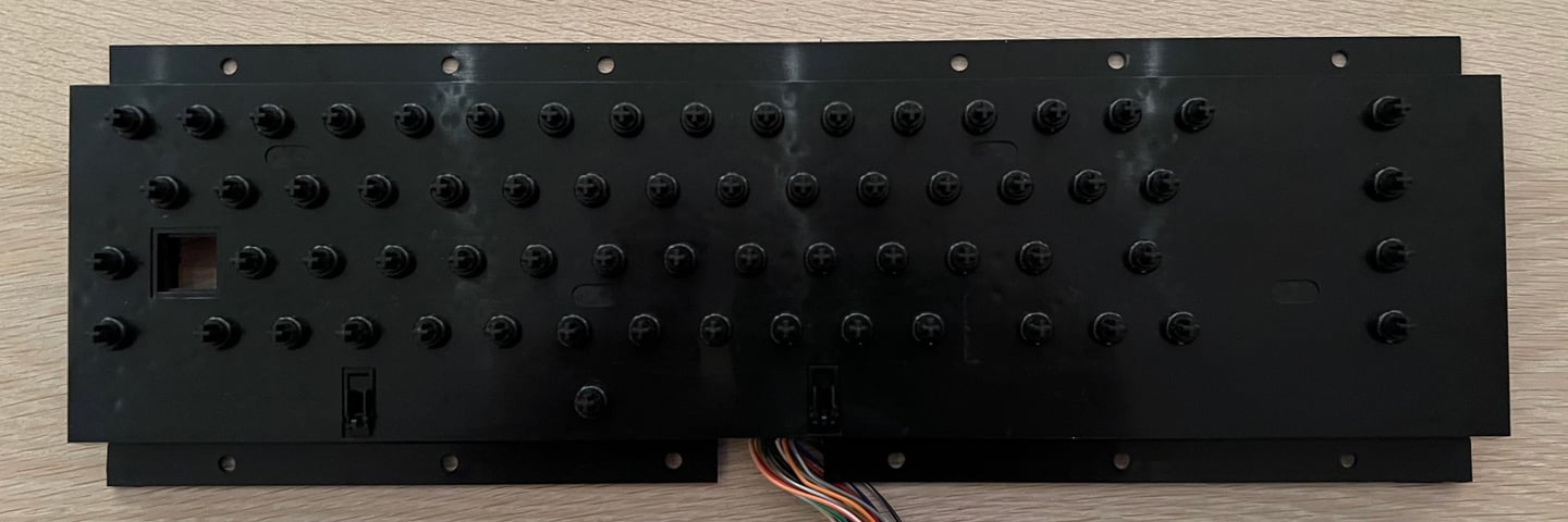
To be able to clean the keyboard PCB it first needs to be removed from the plastic holder. This is achieved by unscrewing the one billion screws at the back of the keyboard. Keep in mind that these screws are really small so it is good practice to keep them in a small jar or plastic bag.

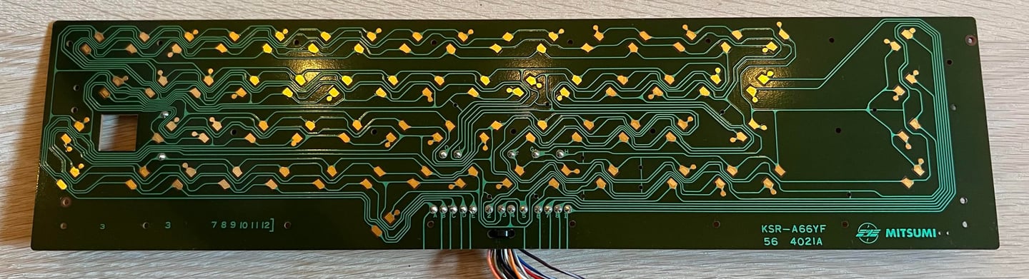
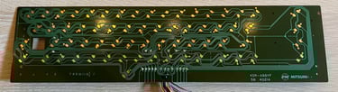
This is a KSR-A66YF PCB from Mitsumi which is a very common model. Since there are no carbon pads on the PCB (only copper pads) the whole PCB is cleaned properly with isopropanol.
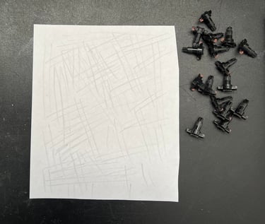
All the plungers are revived by carefully dragging them over a clean sheet of paper. This will remove most of the dirt and grease from the conductive rubber on the plungers. The plastic holder is cleaned thoroughly with mild soap water.

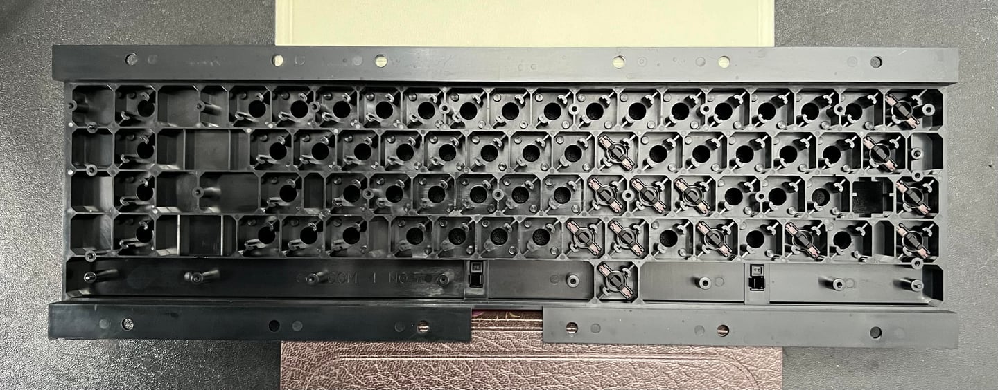
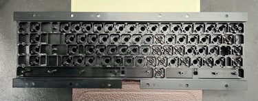
After cleaning and assembly the keyboard plastic holder and plungers look as new (!).
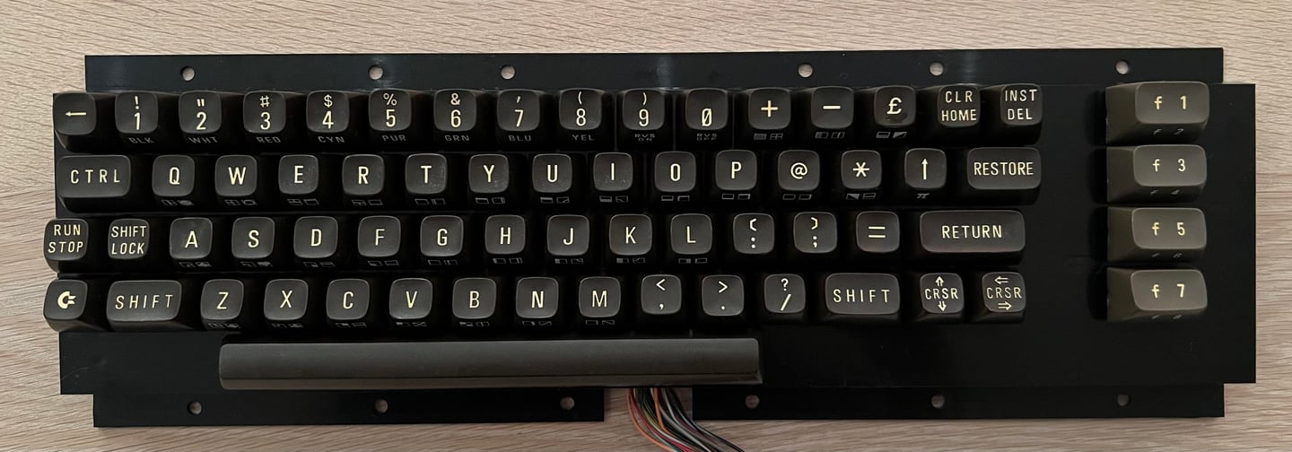
All the keys and springs are put back on the keyboard after everything is cleaned. It looks really good! The front of the keycaps are yellowed, but I am sceptic to retrobright these. The reason for that is that the printing on the front of these old keys are often damaged in the retrobrighting process.
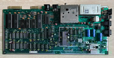
Mainboard
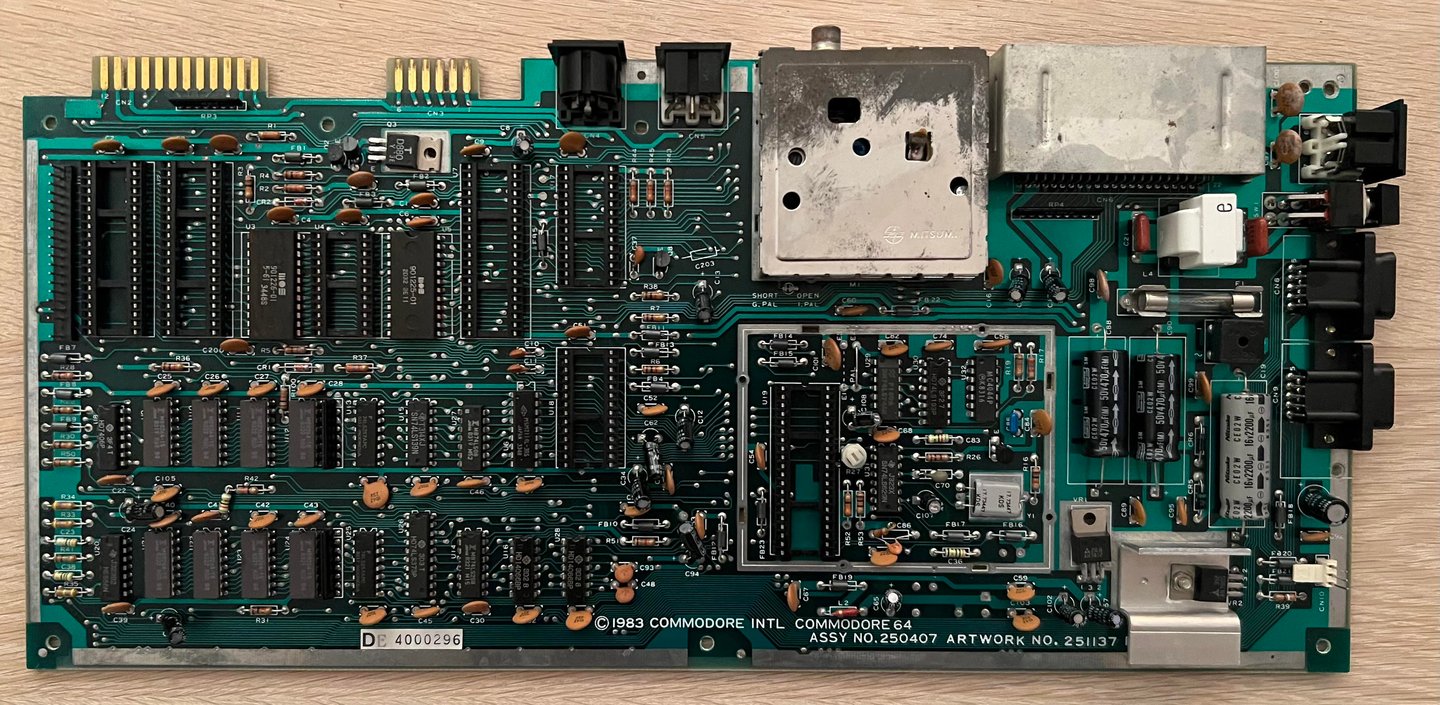
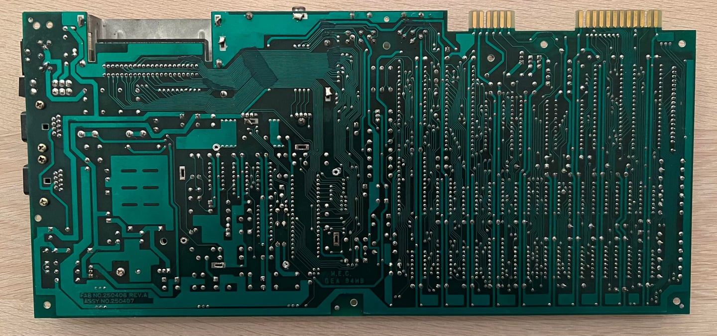
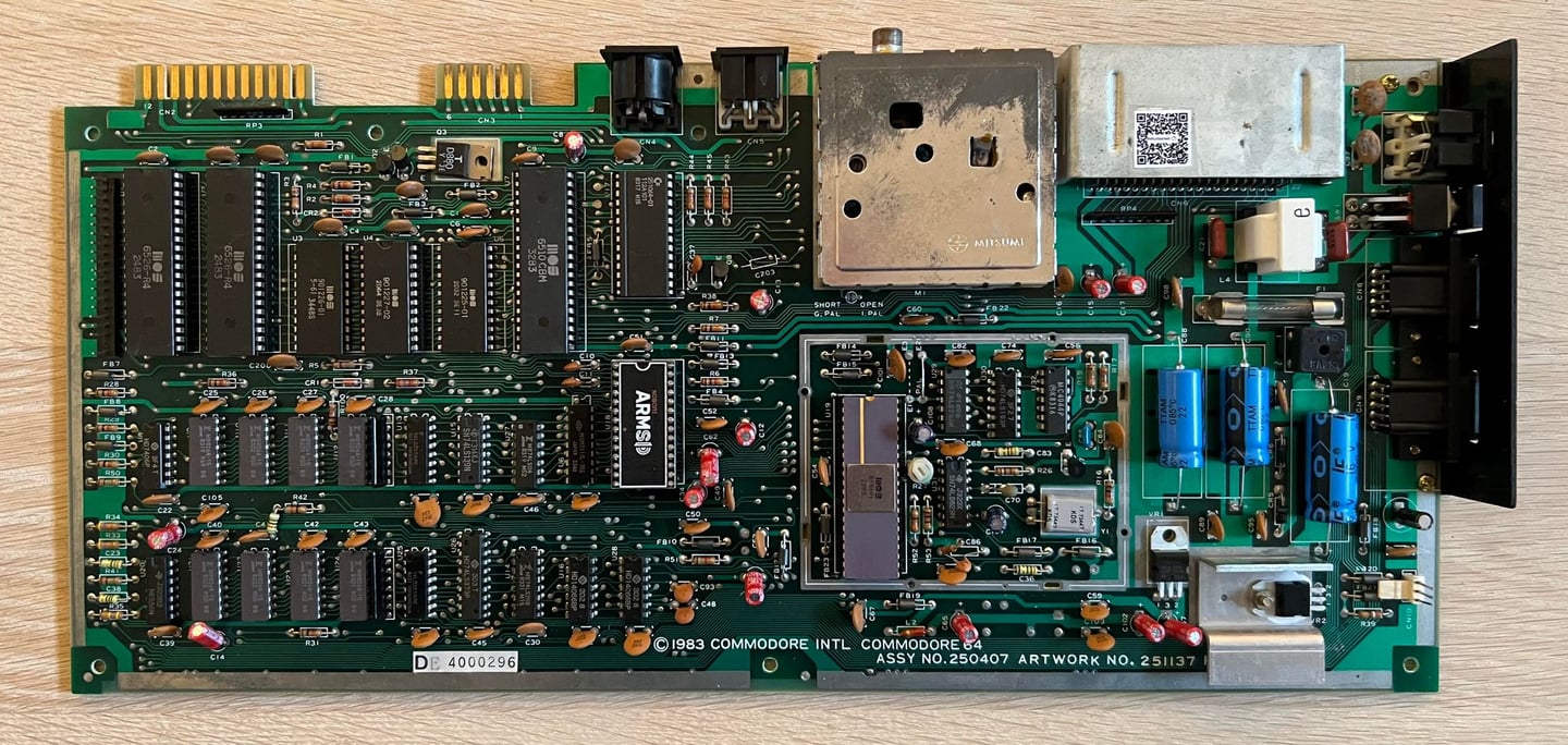
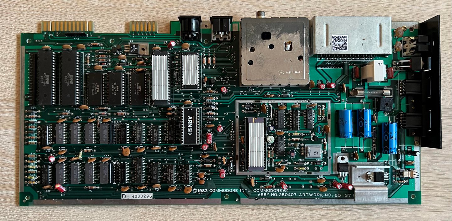
This is a Assy 250407/Artwork 251137 (Rev B) mainboard which is quite common among the "longboard" series with the good old 6581 SID, 6510 CPU and 6569 VIC-II chipset.

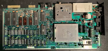
Visual inspection
The top half of the mainboard is full of dust and grease. But I can not see any signs of ripped traces, bulging capacitors, damage or rework. Several of the ICs are socketed, but it appears to be from factory as there are no signs of rework. In the table below the main chips are listed (before refurbishment - some may be changed during repair if required).
As can be seen from the table above most of the ICs are manufactured somewhere around Q2 1983. So it is a fair guess that this Commodore 64 was produced sometime late summer / early autumn in 1983.
Initial testing
Before the machine is powered on for the first time a check for short circuit on the +5V DC and 9 V AC power rail is performed. This is easy to check at the user port – see the article of Checking the C64 voltages for the position of these. Luckily, there are no short circuit so it should be safe to power on.
Powering on the Commodore 64 results in a: BLACK SCREEN.
Not very surprising since these machines are getting quite old, but it now means that repair is required.
Checking the voltages
For the Commodore 64 to work flawlessly all the different voltages need to present and within acceptable tolerances. A detailed article on the subject can be found in the HOWTO - Checking the C64 voltages. In the table below all the measures voltages are listed (this list will also be updated after refurbishment). All the required voltages are present and within tolerances, so there are nothing obvious wrong in that area.
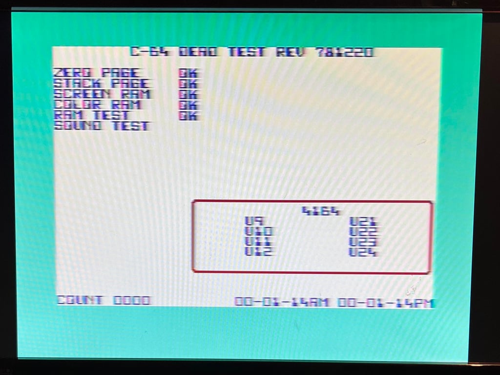
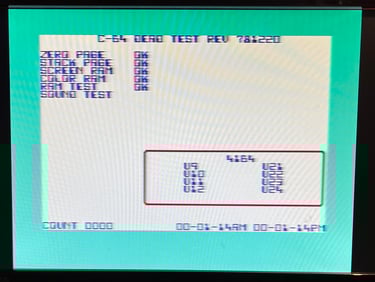
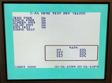
Hot ICs and Dead test cartridge
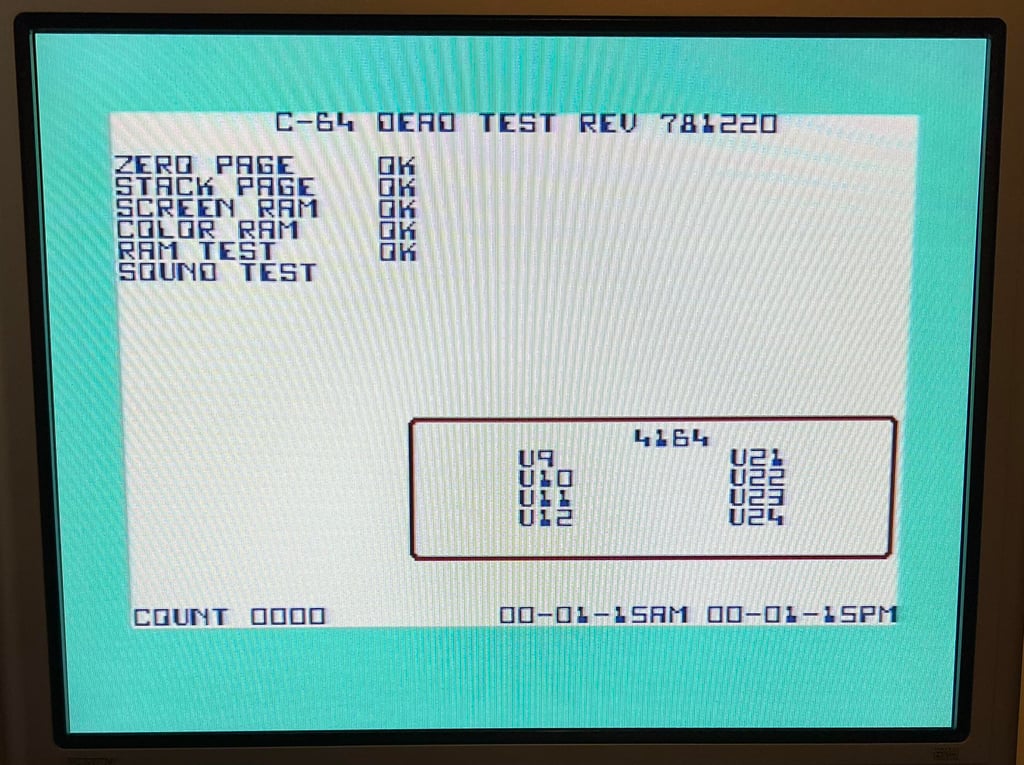
The Dead Test Cartridge is installed in the machine, and while the machine is powered on I also check if any of the ICs are abnormal warm. The ICs are quite warm, but nothing which is not normal as far as I can tell. And the Dead Test Cartridge does not give any signs of life - just a completely black screen. But even if there is a black screen there appears to be a video signal indicating that the VIC-II chip is producing a signal. The Dead Test Cartridge requires the PLA-, CPU- and VIC chip to work so it could indicate that one of these are faulty.
Removal of ICs
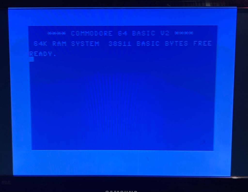
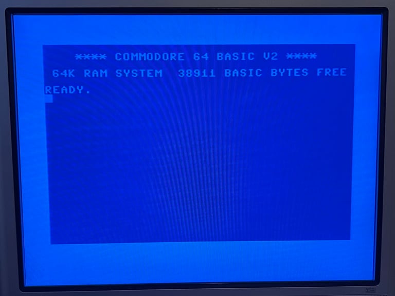
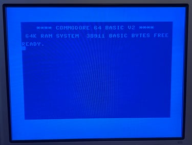
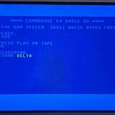
Since several of the ICs are socketed, and several of them are not required for the machine to start the Dead Test Cartridge, the plan is to remove them one by one. First one is the SID chip which is not required at all. And now something nice happens... when the SID chip is removed and the machine is powered on... BLUE BASIC BOOTUP screen (!) It is good to see the blue BASIC screen, but replacing a SID is very expensive.
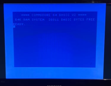
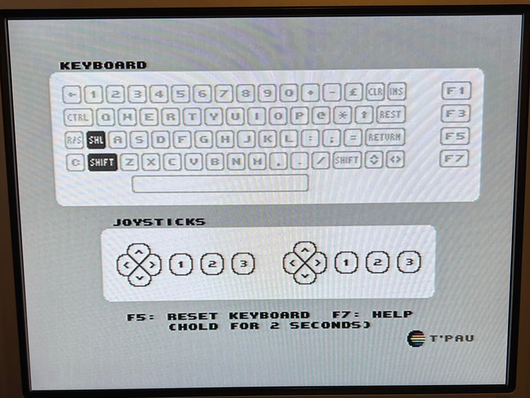
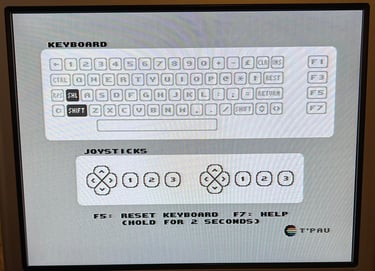
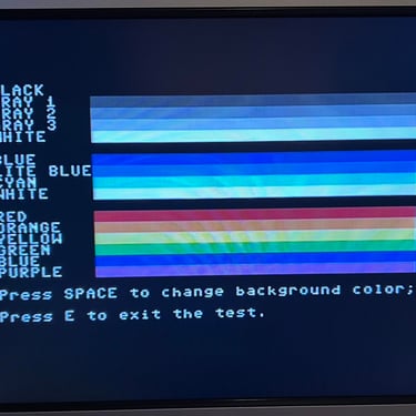
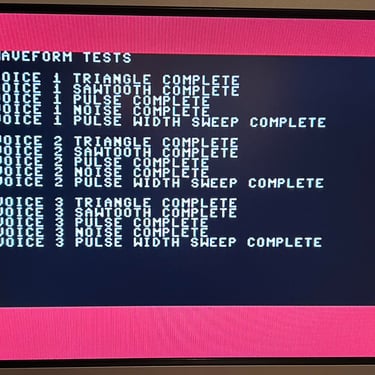
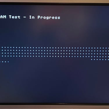
A quick check with the Dead Test Cartridge shows that all simple IC functionality are working as it should. This is of course not a complete test, but so far so good.
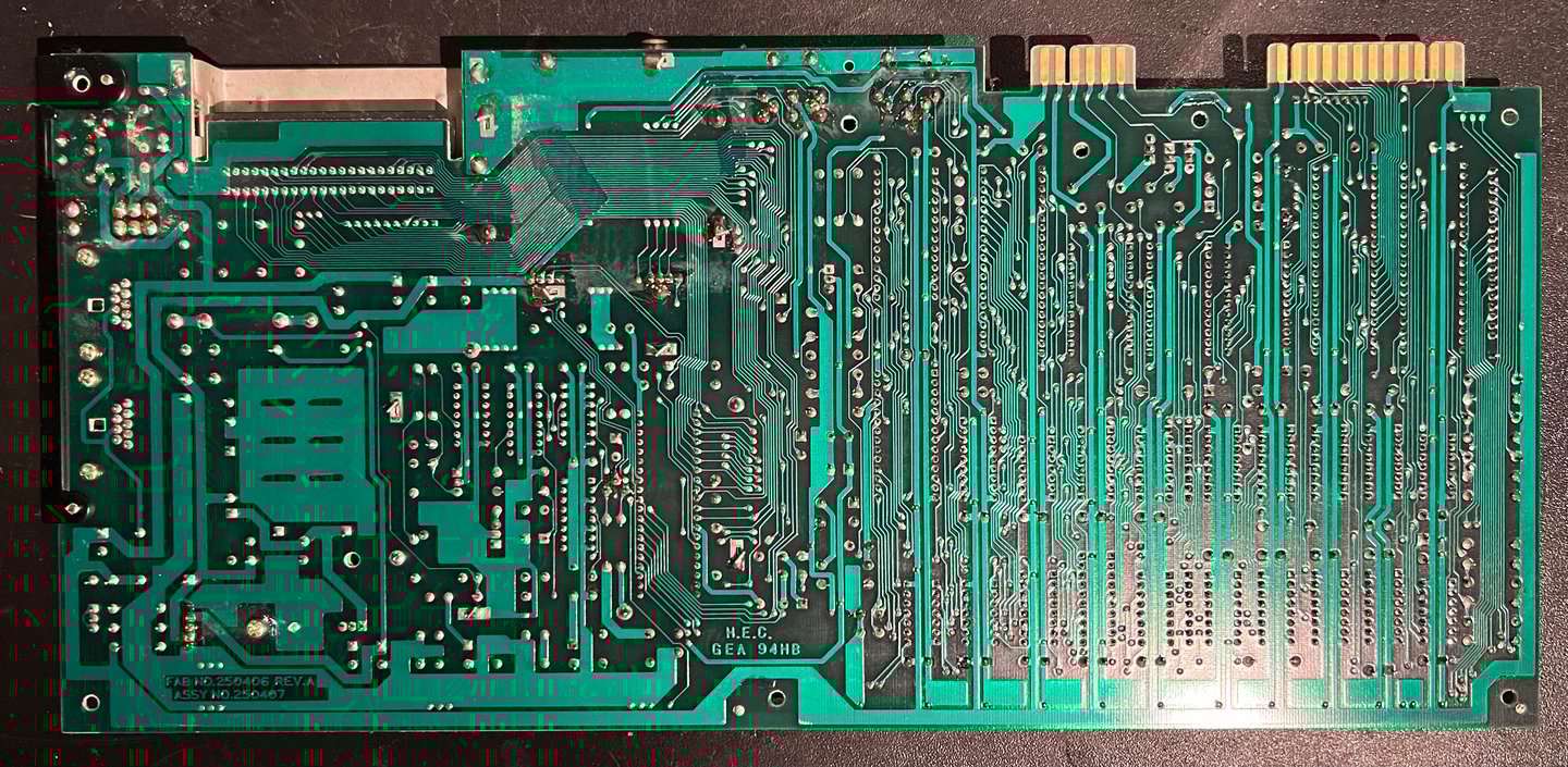
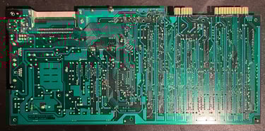
Cleaning the PCB
As mentioned part the mainboard is very dirty. Before refurbishment the mainboard PCB the socketed chips are removed and is cleaned with plenty of mild soap water while using a soft paint brush. Finally the PCB is rinsed with clean water (the tap water in Norway is quite clean). Note that when removing the ICs is important to be careful not to break any pins (or the socket). I use a DIP IC extraction and/or a precision chip lifter. Below are pictures of the mainboard after cleaning, but before any further refurbishment.
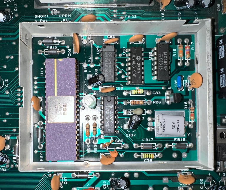
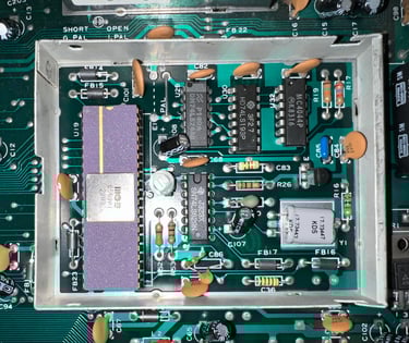
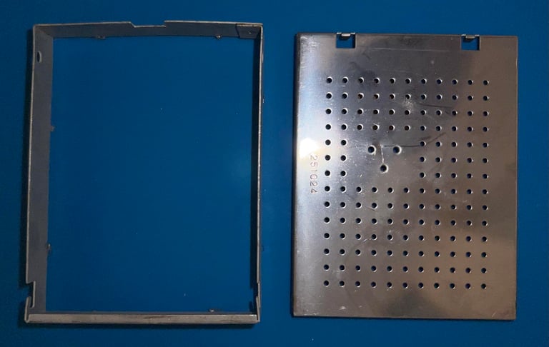
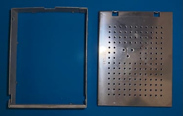
Removing the VIC-II shield
The VIC-II, and its surround circuitry, is encapsulated in a RF metal shielding which also function as a heat sink. But in modern times this shielding has no longer any functionality - it only entraps the heat from the very warm VIC-II. Therefore the RF-shield is desoldered and removed completely.
Replacing the voltage regulators
In the breadbin version of the Commodore 64 there are two voltage regulators on the mainboard. The full story of the purpose of these two can be found in the HOWTO article “Checking the C64 voltages” – but in short these are used to supply the VIC-II circuitry and SID with +5V and +12 V DC.
Since it is crucial that these voltages are both within acceptable tolerances and that the regulators don´t give too high output it is good practice to replace these. The Commodore 64 is pushing 40 years so these old voltage regulators are old – and can fail.
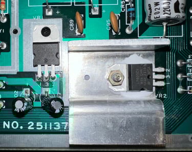
Below is a picture of the new 7805 and 7812 voltage regulators. Note that the 7805 voltage regulator is placed on a heatsink (with some heat paste) and the 7812 is free floating.

Replacing the electrolytic capacitors - mainboard
As part of refurbishment best practice all the electrolytic capacitors are removed and replaced with modern capacitors. The old electrolytic capacitors are over 40 years and all such capacitors will dry out eventually. The list of capacitors can be found here. Please note that C88 and C90 are both 470 uF [50V] compared to what is stated in the capacitor list. This is normal, there are some variations of this version of the mainboard. Below is a picture of the mainboard with the new capacitors installed.


Banner picture credits: Evan-Amos