

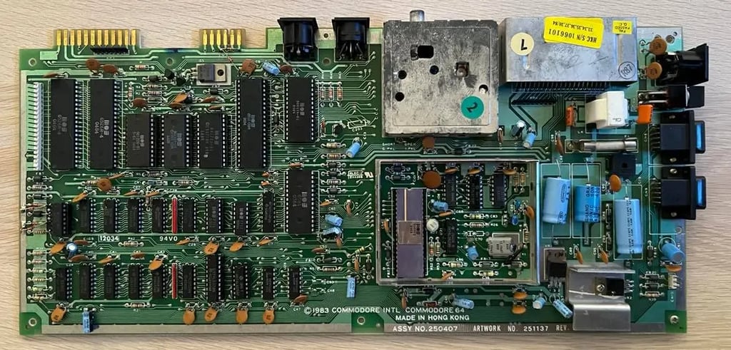
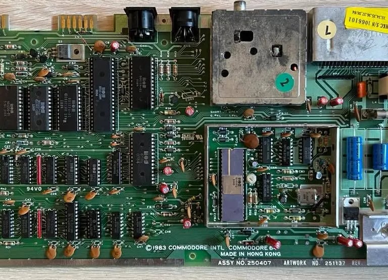
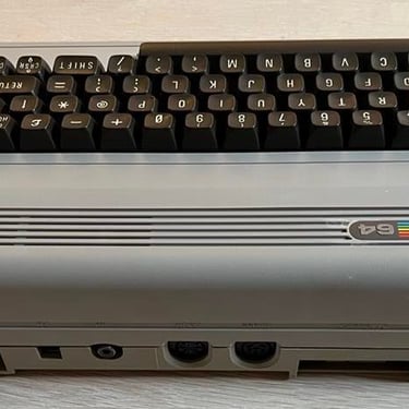
C64 Breadbin
Ser. No. Unknown
Assy 250407
Artwork 211137 (REV B)
Refurbishment plan
To refurbish this C64 breadbin the plan is to do this trough the following steps:
- Clean and restore the keyboard
- Clean and remove stains from the chassis
- Refurbish main board (cleaning, checking, repairing, replacing capacitors and voltage regulators etc.)
- Recap RF-modulator
- Verify operation by testing
Keyboard
The refurbishment of this C64 began some time before this website was operational - so that means that some refurbishing steps does not have pictures.
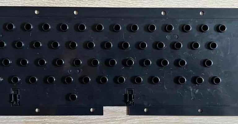
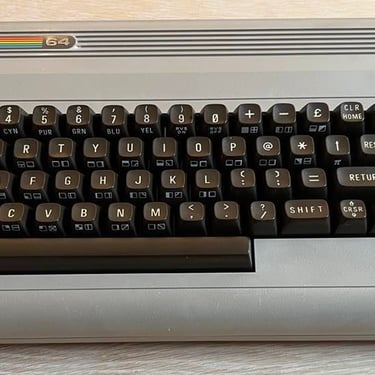
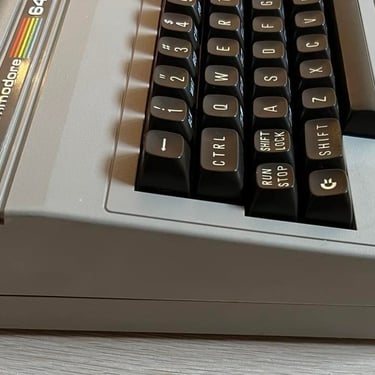
The keyboard is disassembled as ususal into the following parts:
- Keycaps
- Springs
- Plastic chassis
- Plungers
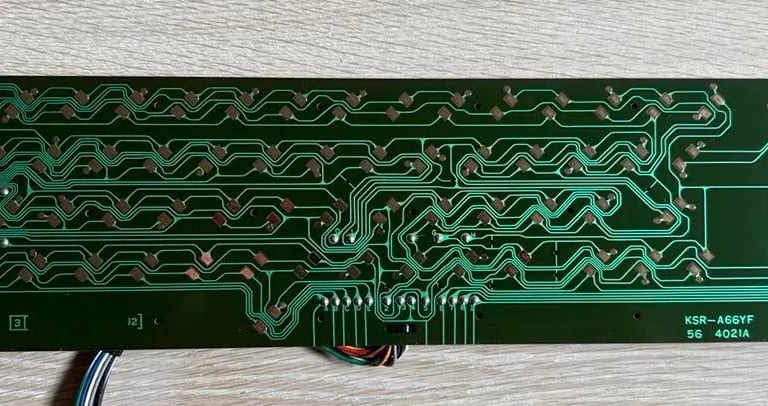
- PCB
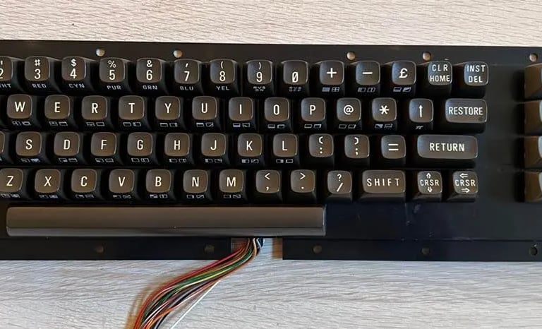
All keycaps are cleaned and rinsed with mild dishwasher soap and left overnight to dry. The printing on the keys are a bit yellow. But I'll leave it like this - this is the good old breadbin with brown keyboard - and I don't think retrobrighting is necessary on this one.
The keyboard is very dirty (sorry, no picture here - but take my word for it). Nevertheless, all dirt and grease is removed from the plastic plate with mild dishwasher soap. The springs also looks quite ok, but they are put in white vinager for two hours and then rinsed with water.
Plungers are not cleaned with isopropaol - instead I use a blank paper and gently remove dirt from the carbon part of the plunger. I've had good results with this method before to revive plungers that are not working properly.
PCB is cleaned gently with isopropanol and a microfiber cloth. I don't find any corrosion on the PCB.Result of the keyboard cleaning in pictures below (click to enlarge).
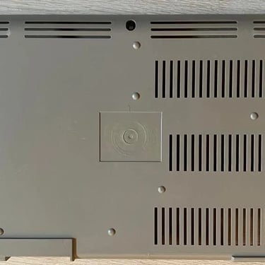
Chassis
It's a pity I don't have pictures before I started cleaning of the chassis. It was a real mess - full of sticky grease, stains and dirt. Also the C64 badge is missing... and where the badge once was there are lots of glue (?) residue. And it's sorry to say but the sticker at the bottom with the serial number is not there:-(
The disassembly is very easy: there are almost NO screws remaining... One (of three) in the main chassis, none in the PCB and even the metal bracket on the right side for the joystick ports have no screws.
The chassis is first cleaned with mild dishwasher soap in luke warm water. This cleaning takes a long time to complete to get rid of most of the grease. After this cleaning the result is much better but there are two areas that needs attention:
1) Badge area: the glue does not come off. I've tried heat, isopropanol, baking soda and grill/oven spray without any noticeable result. I use some P180/P240 sandpaper just to remove the rough edges from the glue. So, the glue marks are still there, but the surface is now smoother. It's not perfect, but I think it's best I can get without risking do damage the chassis.
2) Area below the Power badge: there is an area here that looks like a small lighter patch. I'm not quite sure what this is - and if it's possible to remove. The plan is to try with some glass cleaner and/or baking soda.
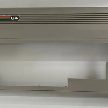
After QUITE a lot of cleaning I'm quite pleased with the result. Yes, there are still marks from the glue residue, but with a new badge (ordered from retroleum.co.uk) I think it looks quite nice now. See pictures below (click to enlarge).
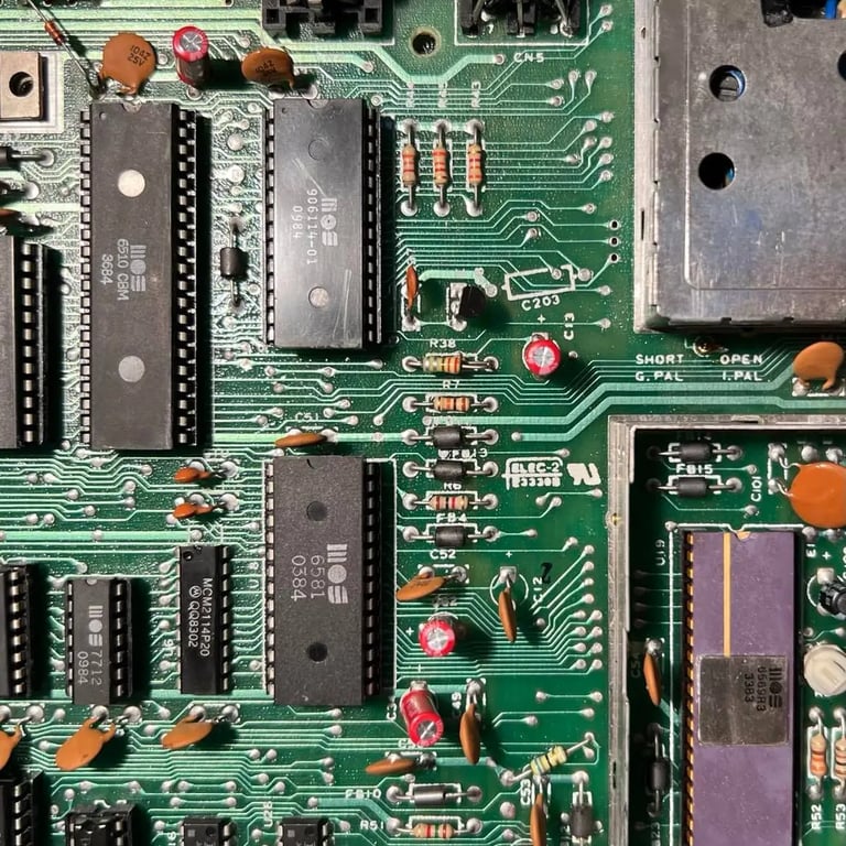
Main board
The main board PCB is full of dirt and dust. Before testing I clean the PCB with some lukewarm water and mild dishwasher soap. Afterwards the PCB is rinsed with plenty of isopropanol to evaporate all liquid. The PCB is left to dry for 24 hours.
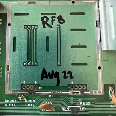
This is the assy 250407 - Artwork 251137 REV B version of Commodores main boards series. You can find a very nice article about this revison at breadbox64.com and at retrorewind.ca you can find all the technical details.
Before turning the main board on I first check for any shortcut between ground and 5V (power), 12 V and 5V (CAN). The last two are checked on the pins of the 78xx voltage regulators. There are no shortcut so it should be safe to turn on - just to be safe I remove the SID chip. The SID chip doesn't need to be present for the C64 to start.
Result: BLACK SCREEN... Classic... Ok, so I need to start fault finding to repair this machine.
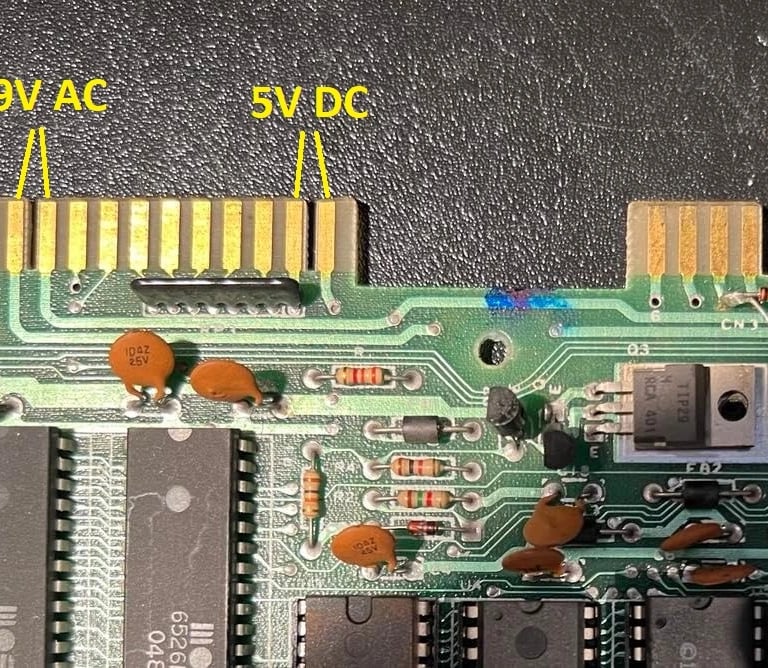
First step is to check voltages. There are four voltages I always check before further fault finding:
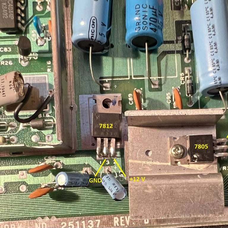
1) 5V from PSU to the powerrail (used by most of the chips except VIC-II)
2) 5V (CAN) with it's origin from the 9V AC from the PSU. Voltage regulated by the 7805. Used as for the VIC-II.
3) 12V with it's origin from the 9V AC from the PSU. Voltage regulated by the 7805. Used for SID chip.
4) 9V AC from PSU
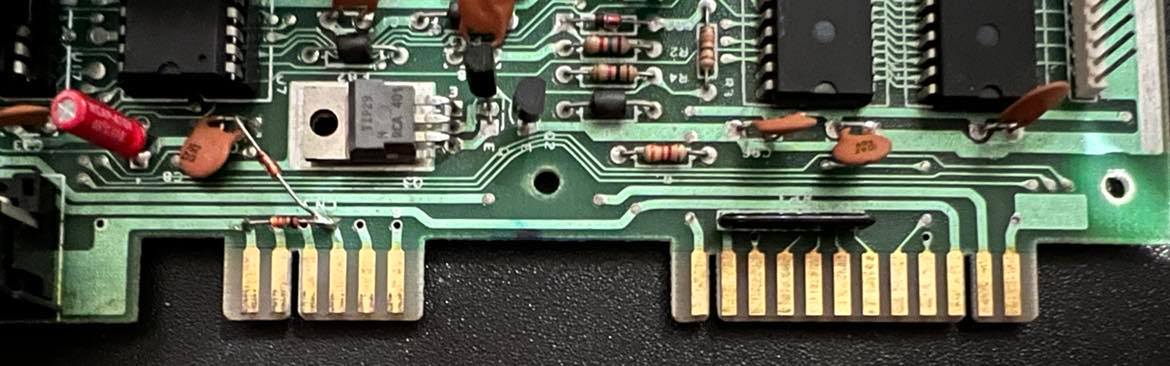
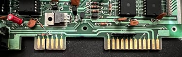
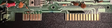
Voltages 1) and 4) are measure at the user port, and voltages at 2) and 3) are measured directly on the voltage regulators. In the pictures below you can see where these measuring points are (click to enlarge).
All voltages are ok. Still, there could be chips which don't get the 5V from the powerrail, but I can't see any broken traces. And none of the chips are warmer than normal.
The next step is to test with the dead test cartridge, but the result of this is still a black screen. The dead test cartridge will display a black screen if chips such as PLA, CPU and VIC are broken. In the main board both the VIC and CPU are socketed so I check these in a known working C64. This test show that both the CPU and VIC are ok.
PLA chips is often a prime suspect when a C64 produce a black screen. The PLA is desoldered, a new socket soldered in, and the chip is tested in a working C64 - with the result that the PLA is working also...
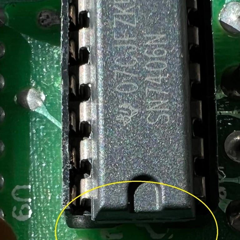
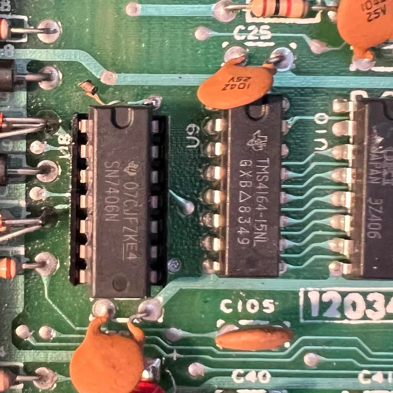
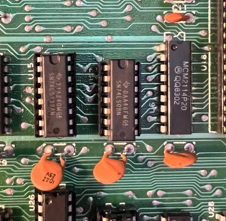
Now, this is a point where I probably should bring out the oscilloscope, but I notice that quite a few of the logic chips (such as NAND etc.) are MOS chips. And these are quite famous for failing. So, the MOS 7707, 7711 and 7712 are desoldered and new sockets soldered in. And... these also works! Argh... Anyway, it's good to have these in sockets since these chips should be replaced anyway to make the C64 a bit more "future proof". During the testing I manage to break the MOS 7707 so I replace this with a 7406 from Texas Instruments.
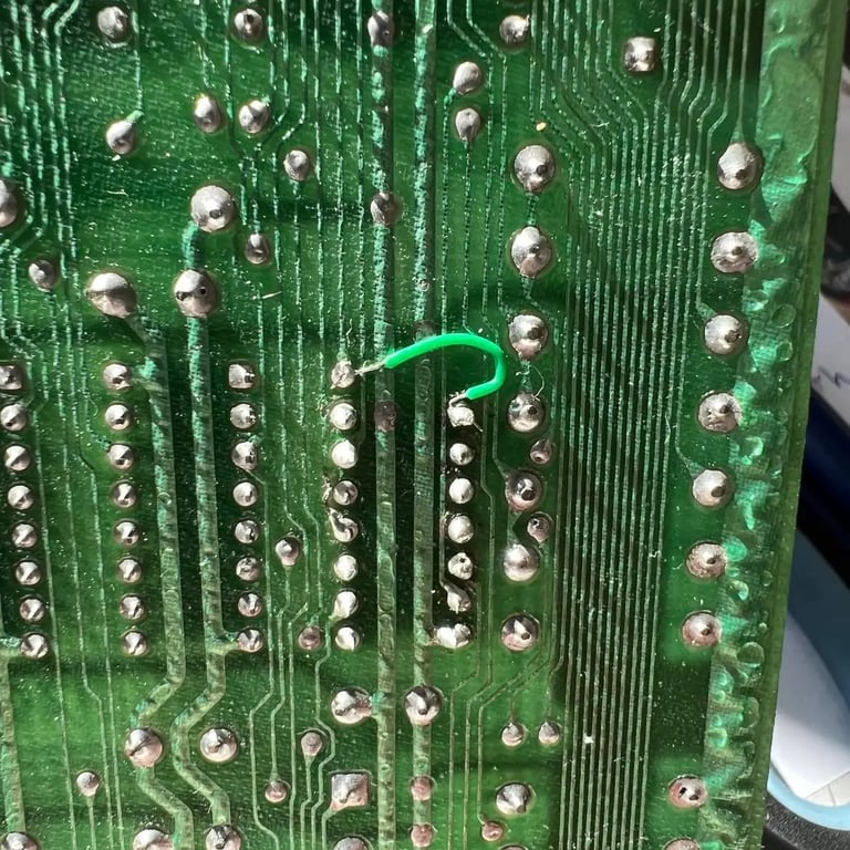
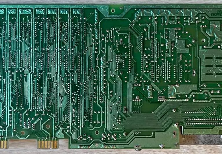
While desolering the MOS 7707 I accidently lifted and broke a trace. This can happen even if you are careful... But luckily it's easy to fix. Below you find two pictures where you can see the lifted trace and also the fix with the bodge wire on the backside of the PCB.
While working on the main board I've noticed that the BASIC and Kernal ROM have a pin each which looks like it's cut and soldered. This is (or was) a quite common way of fault finding; cut the power to the chip to see if that helps. If not - solder the pin back in. None of these chips get warm so I don't think is the problem. And also the dead test should work without these in operation - unless they corrupt the data- or address lines. Nevertheless, I desolder these (and install sockets) to test them. When desoldering these I see that the legs/pins are in fact cut.
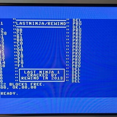
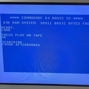
Now something happens! When I test with the dead test (with only the character ROM in place - the other two out) the cartridge displays a picture! And the test is good! So this shows that the BASIC or Kernal (or both!) are defect. I now borrow a BASIC and Kernal ROM from a known working C64 - and LO AND BEHOLD - it works! The ROM chips are defective. This is very good! There still could be more problems, but now the good old blue screen is displaying 38911 BASIC bytes free :-)!
I order replacement chips 901226-01 (BASIC ROM) and 901227-03 (Kernal ROM latest version) from www.retroleum.co.uk.

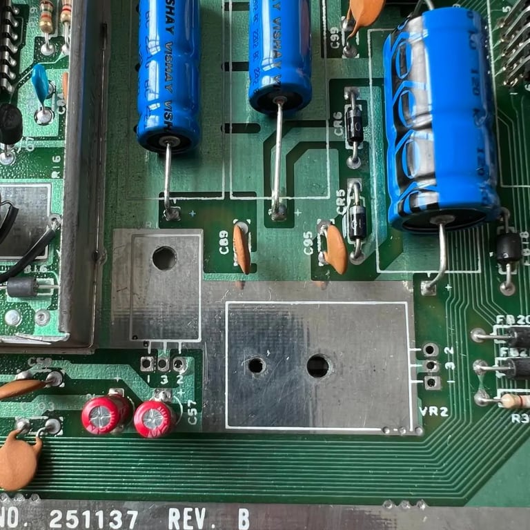
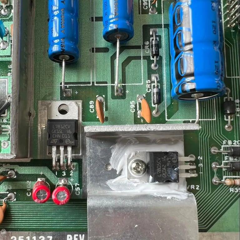
Next step is replacing the electrolytic capacitors on the main board. I can't see any leakage from the old capacitors, but these are almost 40 years old. And electrolytic capacitors dry out - so they should be replaced. I need quite a few capacitors for other projects as well so this time I order the capacitors from Mouser electronics (otherwise it's very easy to order from www.retroleum.co.uk).
All electrolytic capacitors are replaced with Panasonic Vishay and Wurth Electronics components. Pictures below show the result (click to enlarge).
Then I remove the old 78xx voltage regulators and replace these with new ones. Please note that the 7812 (12V) regulator is not attached to the PCB with a screw. This is normal from factory. But the 7805 (5V) is attached with a screw and nut - and also I clean and apply fresh heat paste on this. This might look a bit messy, but it's to increase the heat transfer away from the regulator.
The user- and datasette port also needs some cleaning to make sure we have good connectivity when attaching peripherals. A clever way to do this is to use a rubber eraser (yes - your old school rubber) and gently rub it over the copper connectors. Be careful to not rub too hard. After the main residue is gone I gently clean it with isopropanol. The difference is quite significant. See "before" picture below (top) and "after" picture (below). Click to enlarge.

I decide to replace the MOS logic chips with new ones. As mentioned before the MOS 7707 broke during desoldering and was replaced with a Texas Instrument 7406 chip. I now replace the MOS 7711 and MOS 7712 with Texas Instruments 74LS139 and 74LS08 respectively. Even if these two MOS chips are working ok, they are quite famous for failing frequently. So it´s a good thing to get these replaced. An overview of MOS xxxx to TTL equivalents can be found here: https://www.c64-wiki.com/wiki/MOS_Technology_Products.
Voltage table
RF modulator
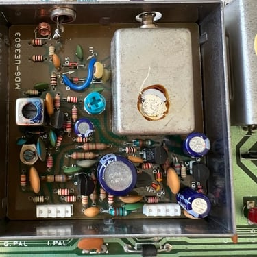
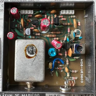
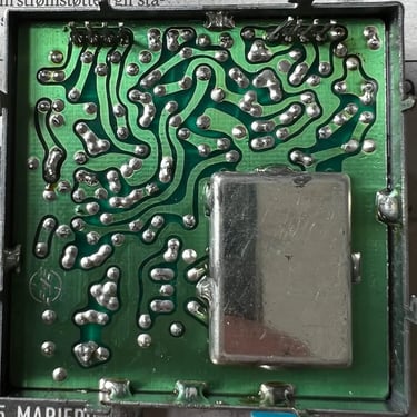
There are also a few electrolytic capacitors in the RF-modulator; 10uF, 470uF and 2x 100uF. It can be tricky to remove the RF-modulator so I recommend to don't rush it when doing this - otherwise it's likely to break traces either on the main board PCB and/or in the RF-modulator PCB.
The way I remove the RF-modulator:
- Bend all the tabs to that they are clear of the little rectangle hole to pass
- Use plenty of flux on the large pins connecting the RF-modulator to the main board. I use my desolder station to remove the solder, but when doing this I also use my other solder iron to heat the solder at the points. This makes it easier for the desolder station to suck up most of the solder. Afterwards I use some solder braid to try to get the rest.
- There are eight pins connecting the main board PCB to the RF modulator PCB. You can think of this as "four pins" transferring signals in to the RF modulator and the remaining "four pins" to transfer signals from the RF-modulator to the main board. I reflow these points with fresh solder and then use the desolder station to remove the solder.
- I then gently(!) put a small screw flat headed screwdriver at the end of the chassis and use my hot air gun to carefully loose the chassis. This can be tedious work, but if you are careful the result is good.
Below you find four pictures of the RF modulator: 1) with old capacitors 2) with new capacitors 3) backside of modulator PCB 4) main board with RF modulator desoldered.
Heat sinks
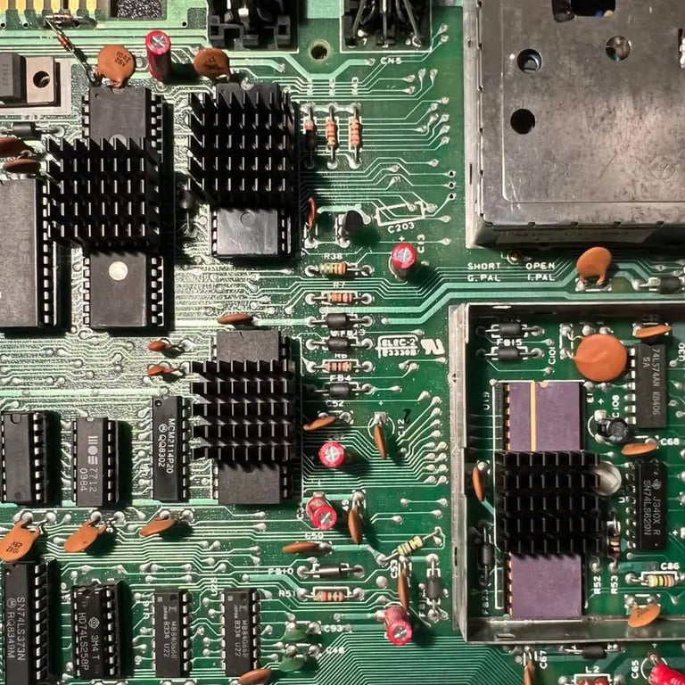
Heat can reduce the lifetime of old chips so as a preventive measure I add heat sinks at four chips; the SID-, VICII-, PLA- and CPU chip.
Also note that I remove the top shield from the VICII circuit area. This shield was originally part of the FCC certification, but is to no use now. When this shield is removed heat is less trapped in the case. Also, I remove the cardboard shielding for the main board. As with the VIC circuit this shield have no real purpose any longer - and only keeps heat inside the chassis.
Testing
Before starting the joy of testing I need to collect all the missing screws. Luckily I got quite a large collection of screws so I manage to collect screws for the PCB and the metal bracket for the joystick/power ports. Note: There should be 7 screws for the main PCB, but only 6 are used. The reason for that is that the bottom right screw can't be mounted due to a small broken plastic part. I don't this makes any difference. The PCB is well mounted with the 6 screws. The screws for mounting the keyboard and also the screws for mounting the bottom to the top cover I can´t find any replacement for. So these I order new ones from retroleum.co.uk together.
Now, with all screws in place (except for one missing in the PCB - but which does not impact any function) testing begins!
The way I do the testing is:
1) With the Dead test cartridge
2) With the Ultimate II+ cartridge
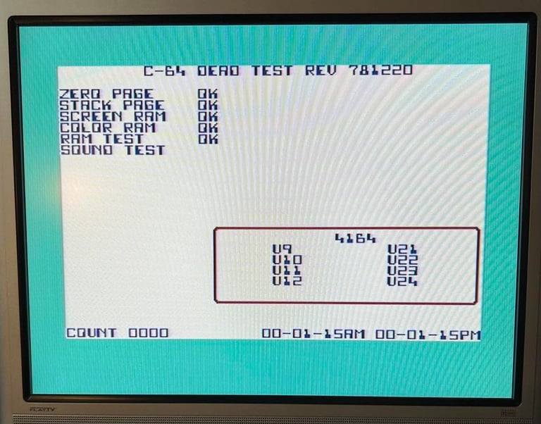
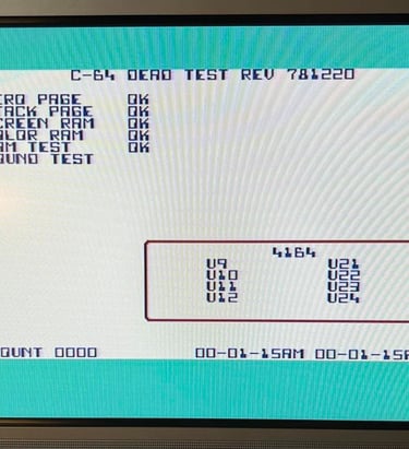
The Dead test cartridge is a very nice tool. It will check the most important C64 chips (RAM, Color RAM, PLA, SID, CPU and VIC). Also, the dead test gives an indication if the CIA chip is ok by showing two timers at the bottom of the screen. These must be identical (except showing PM/AM) for the CIA to be ok. So any major issues here we´ll notice. When testing with the Dead Test with this C64 everything works ok:
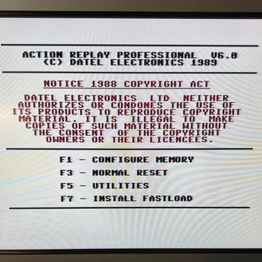
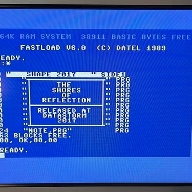
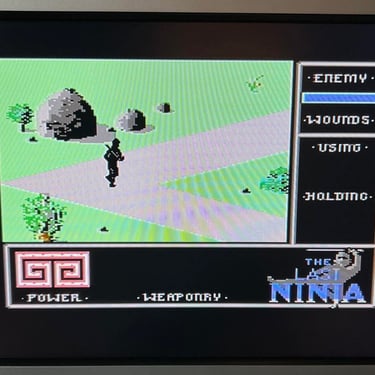
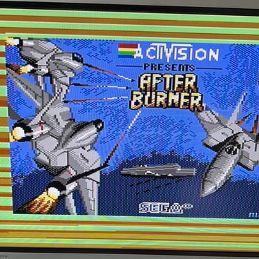
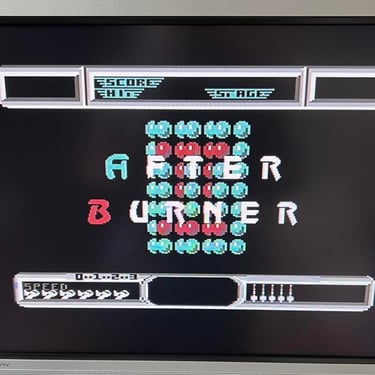
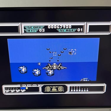
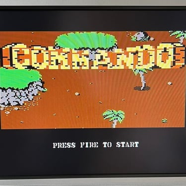
Next, I use the Ultimate II+ cartridge to test:
- Floppy access
- Loading from datasette
- Cartridge
- Check audio/video/keyboard/joystick
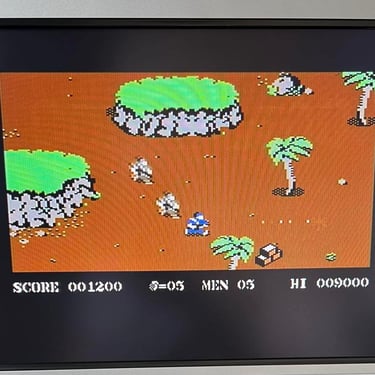
As far as I can see everything works fine! I´m quite happy with the result - and there´s just something special with these old breadbins!
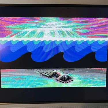
Below you will find a few screenshots from the testing (click to enlarge).
"A picture worth a thousand words"
Below is a collection of the final result from the refurbishment of this C64. Hope you like it! Click to enlarge!
Final result
Banner picture credits: Evan-Amos