

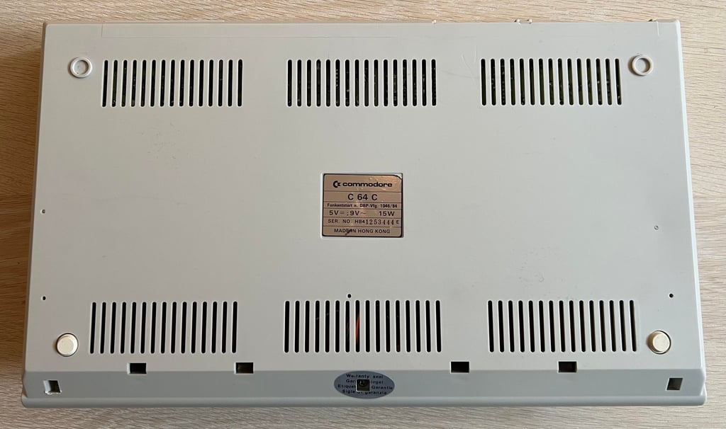
C64C [PAL]
Ser. No. 1253444
Assy 250469
Artwork 252311 (REV A)
Starting point
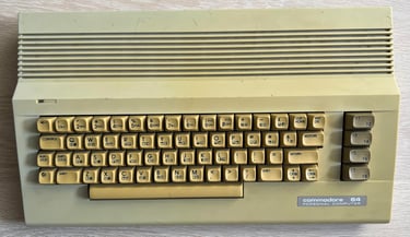
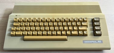
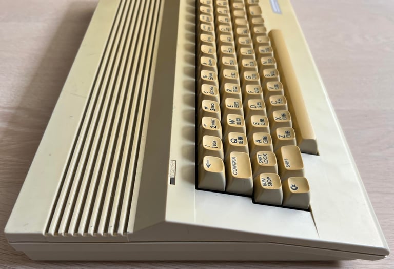
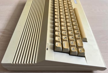
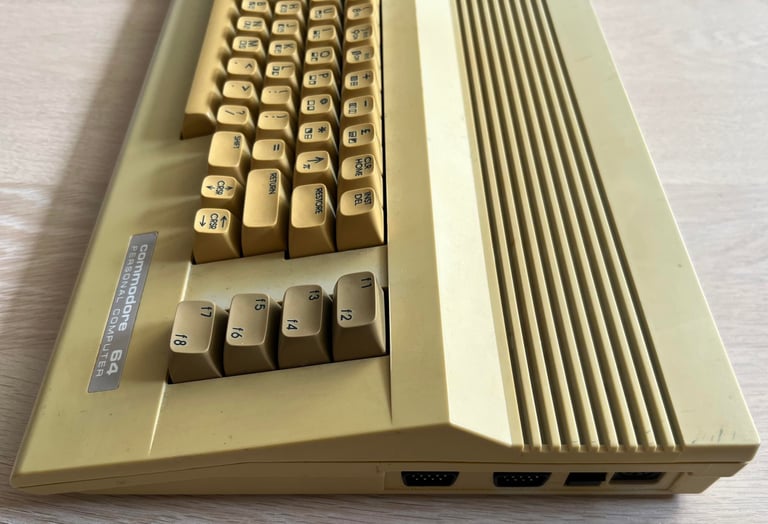
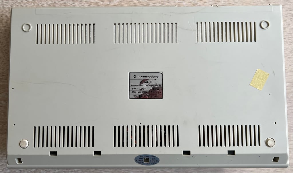
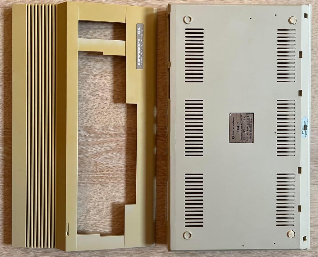
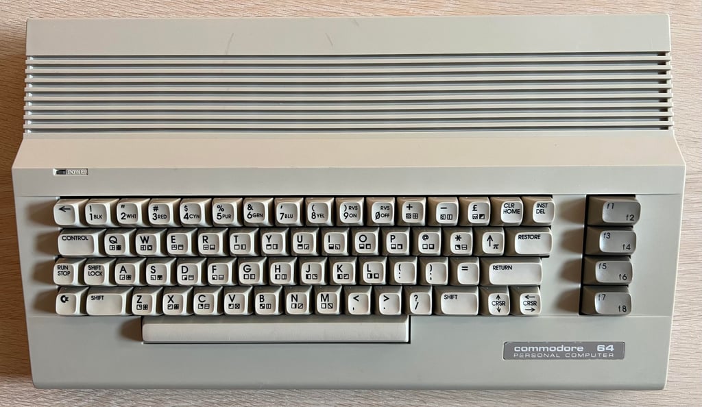
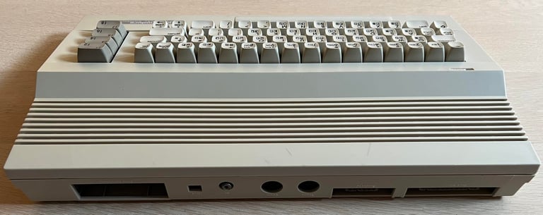
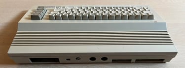
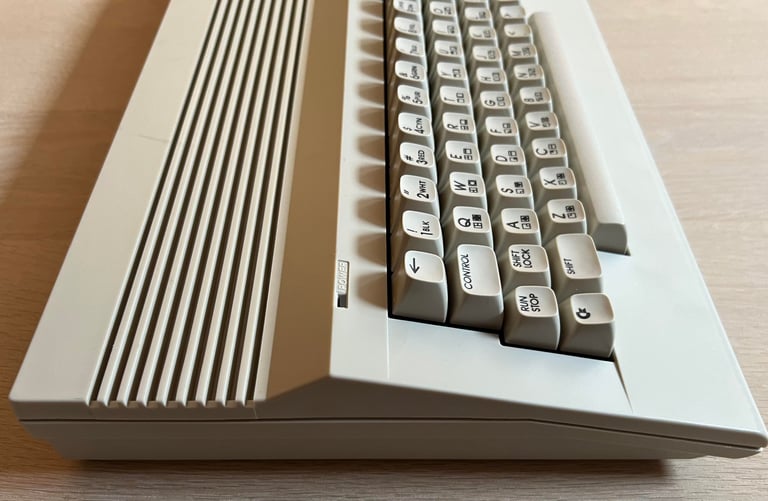
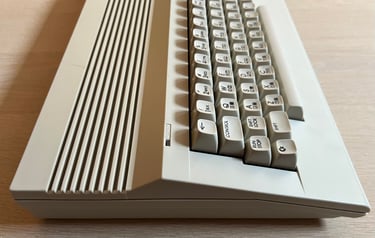
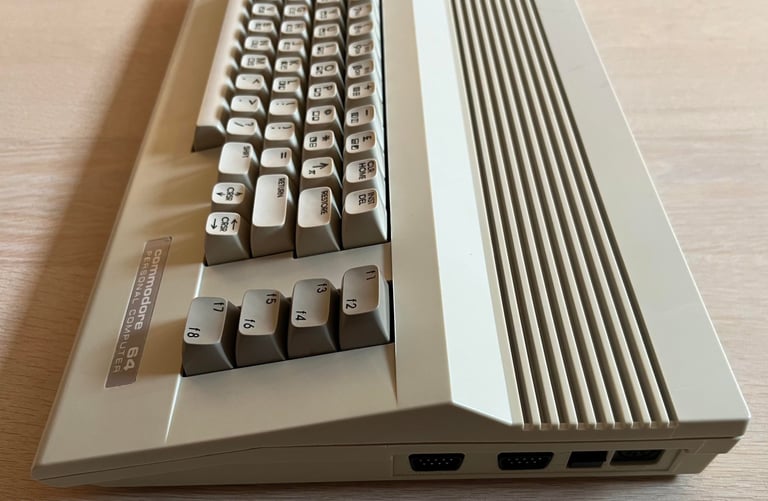
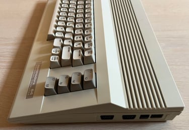
Holy moly... one word sums up the impression of this C64C: Gouda cheese. It is so yellow that it hurts my eyes. So this will be a nice challenge! Notice that the yellowing is worst on the right side of the top cover, and the flat side of bottom cover is hardly yellowed.
Nevertheless, neglecting the yellow casing and keycaps it looks quite ok. All keycaps, springs and plungers feels intact. It is quite dirty, but this is to be expected. There are also some signs of use and cable marks. I do not know if the machine works or not yet.


Refurbishment plan
The refurbishment plan for this C64C (order can vary and some of the tasks will be done in parallell):
- Refurbish the casing (cleaning, repairing and retrobrighting)
- Refurbish the keyboard (cleaning, reviving the plungers and retrobrighting)
- Refurbish main board (cleaning, checking, repairing, replacing capacitors, adding heat sinks etc.)
- Recap RF-modulator
- Verify operation by testing
The plan can be updated during the refurbishment process. Sometimes I discover areas that needs special attention.
Disassembly
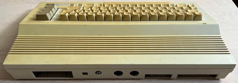
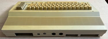
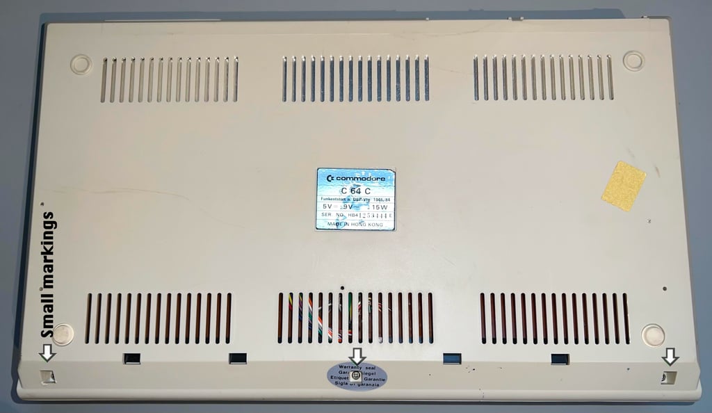
The Commodore 64C casing consists of a top- and bottom cover held together with rear clips and three screws (see picture below for the position of the screws). When removing the three screws at the bottom cover I notice that a previous owner (or repair person) has used a somewhat large screwdriver on the left hand side. I notice some markings both in the plastic and the metal in the screw. Not a big thing, but I think it is important to use the correct tools when doing refurbish and/or rework.
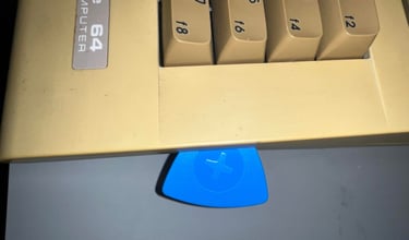
A small plectrum looking tool (from iFixit) is used to carefully release the top cover from the bottom which is hinged together with some small plastic clips.

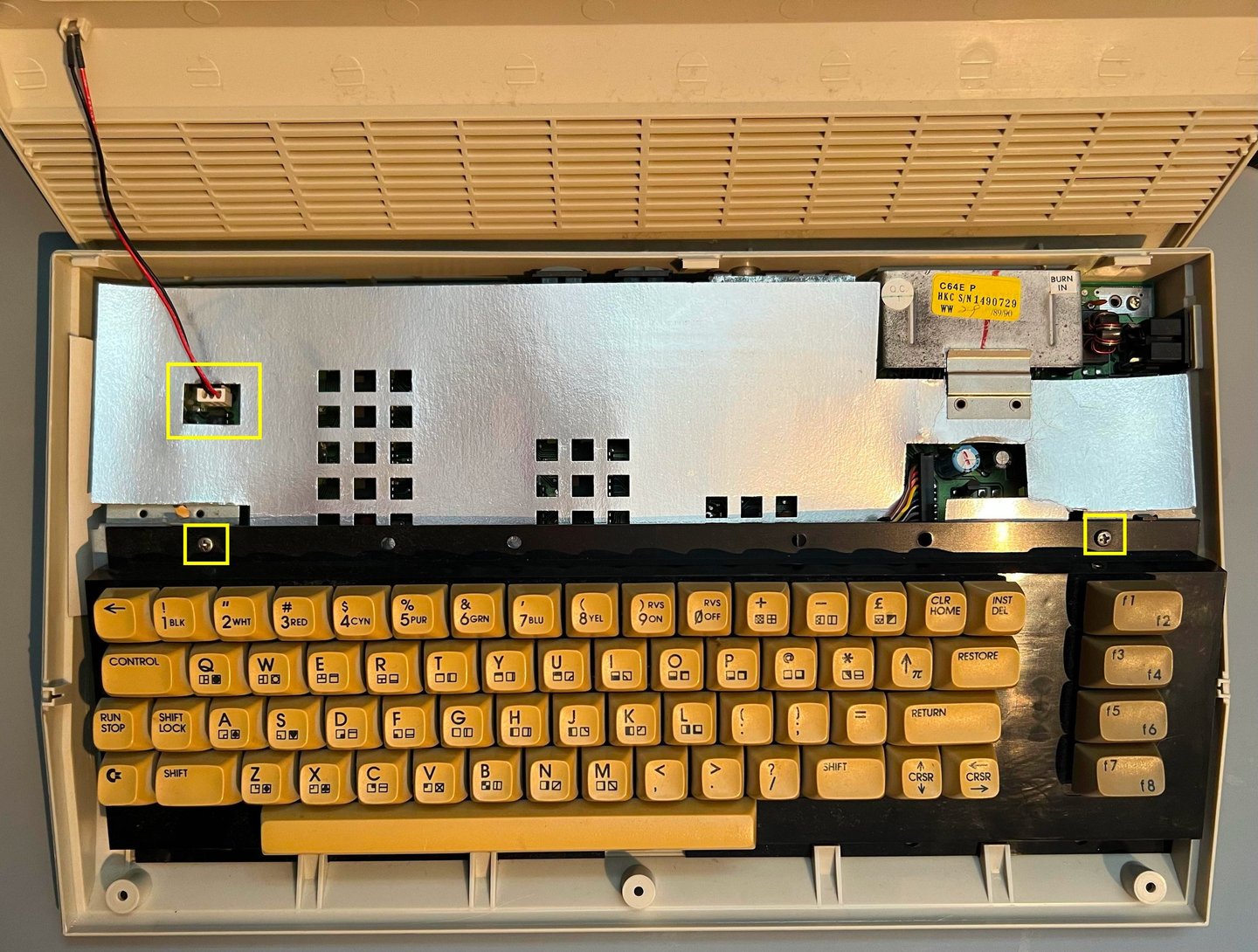
The top cover is carefully lifted about 30 degrees and wiggled loose from the rear hinges. Now the inside is revealed; it looks very nice and tidy. There are some dust and grease obviously (a bit more than is visible in the picture), but other than that it looks fine. The LED connector is removed and the two machine screws holding the keyboard in place are also removed (see yellow squares). I know it is hard to see these yellow squares due to the Gouda looking keyboard... oh my...
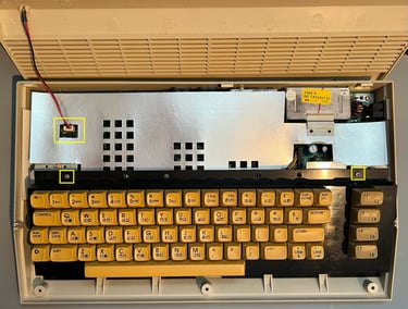
While tilting the keyboard slightly the keyboard connector is removed (see yellow rectangle in picture below), and the keyboard is removed completely. The RF-cardboard shield is lifted away and not the complete PCBA mainboard is revealed. It looks to be in very good condition. Only some dust and grease which is expected.
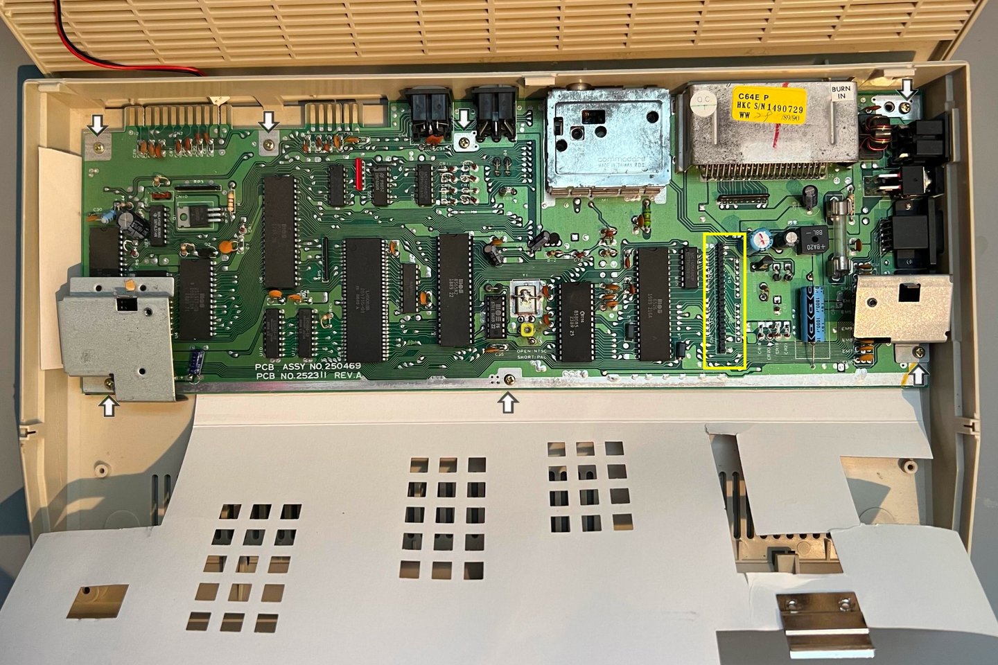
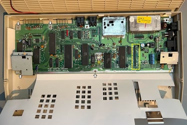
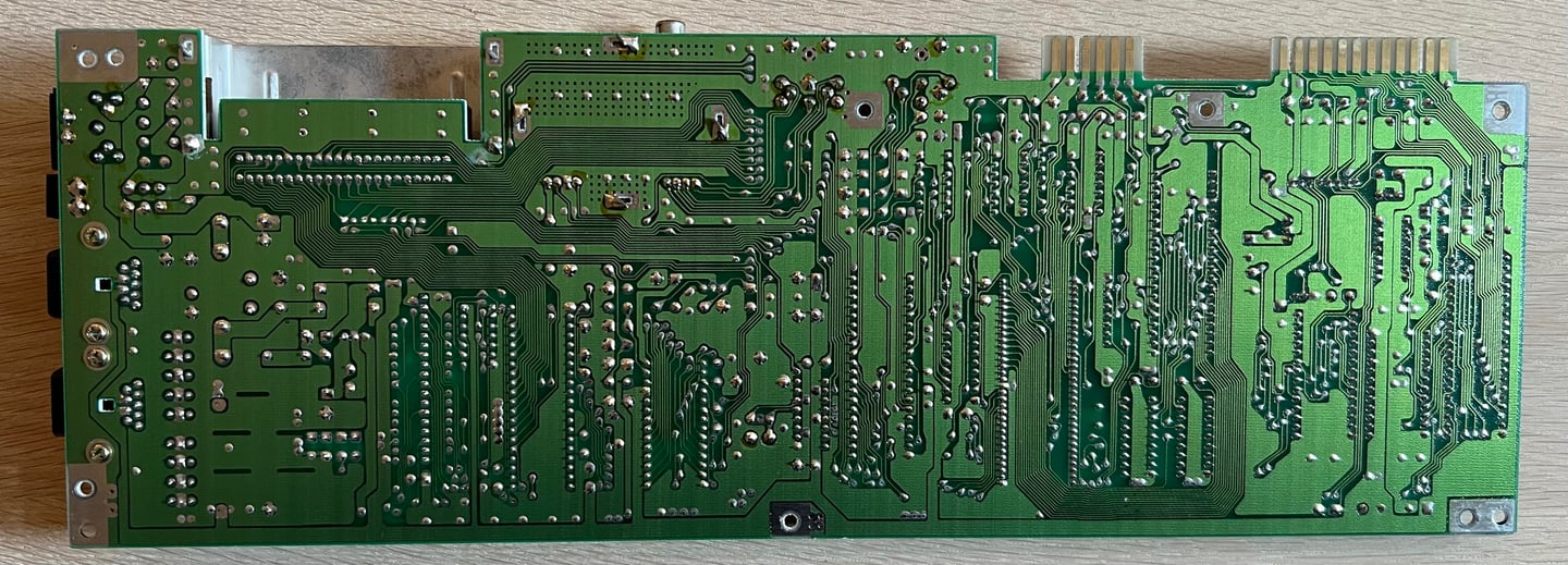
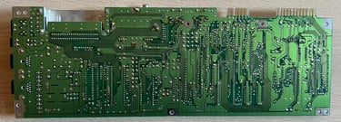
To complete the disassembly the two support metal brackets for the keyboard are removed (two screws) and the remaining five screws holding the PCBA mainboard to the bottom cover are removed (see arrows in picture above).
Exterior casing
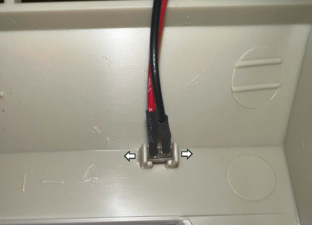
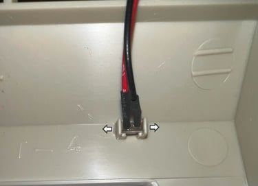
Before cleaning the top- and bottom cover the LED is removed. This is not very complicated, but it is wise to be careful when pushing the small plastic tabs away from the LED - the plastic tabs can easily break.
The covers are placed in mild soap water for about 48 hours. This is to remove dust and grease which is very important for a successful retrobrighting.
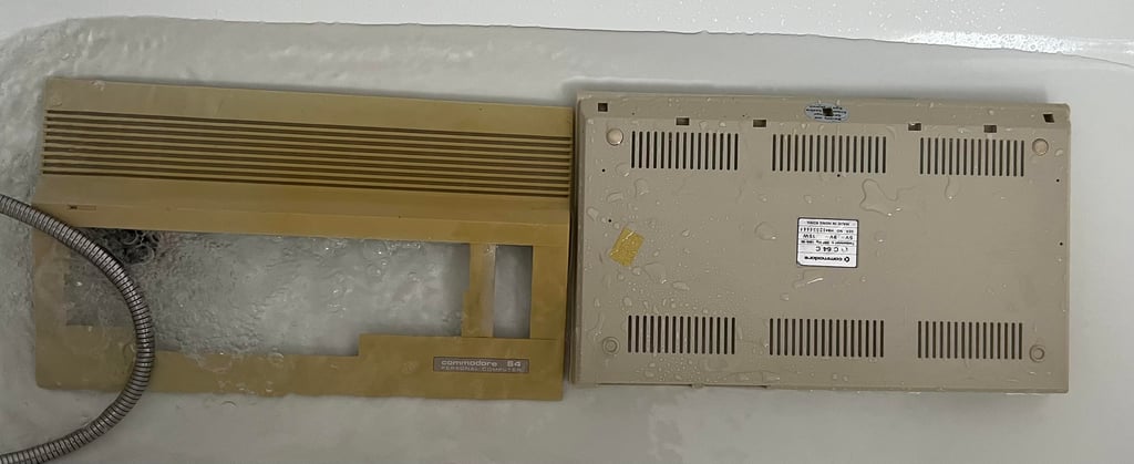
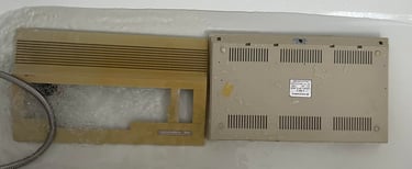
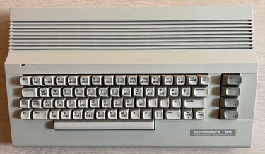
Both covers looks much better after cleaning. They are still (at least the top cover) very yellowed, but now they are very clean which is good.

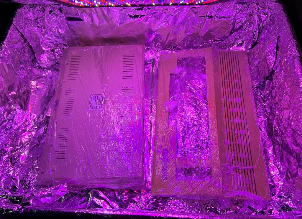
Next action is to retrobright the covers. They are covered with 12 % hydroperoxide cream, cling wrapped and placed in a UV container for 2 x 12 hours. The cream is replenished about every hour to avoid it from drying out.

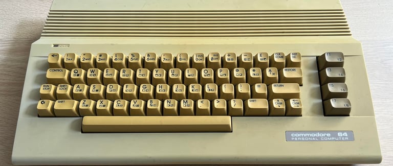
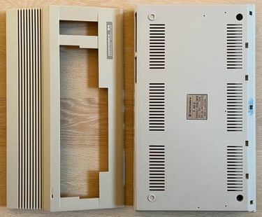
The result after retrobrighting is very good I think. Most of the yellowing is gone! There are still some cable marks, but I think I will leave these as they are. The reason for this is that there is more risk damaging the covers by sanding the marks.

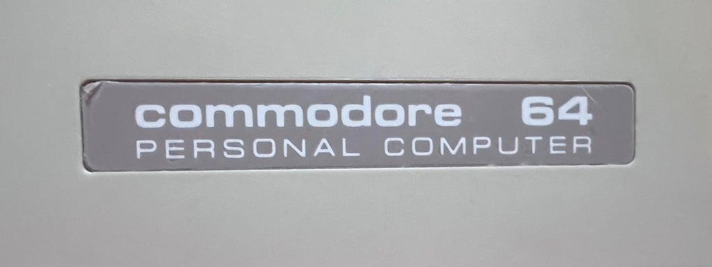
Not really sure, but I think that the thin plastic film covering the "Commodore 64 personal computer" is still present (?). If so, I leave it to the future owner to decide whether to leave it as it is or tear it off...
Keyboard
In addition to some obvious need of retrobrighting the keyboard needs to be properly cleaned. But aside from the yellowing and dirt the keyboard appear to be in very good condition. There is not much sign of use and all keycaps, springs and plungers appears to be ok (whether or not the plungers make good contact will be checked later).
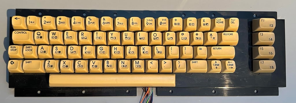

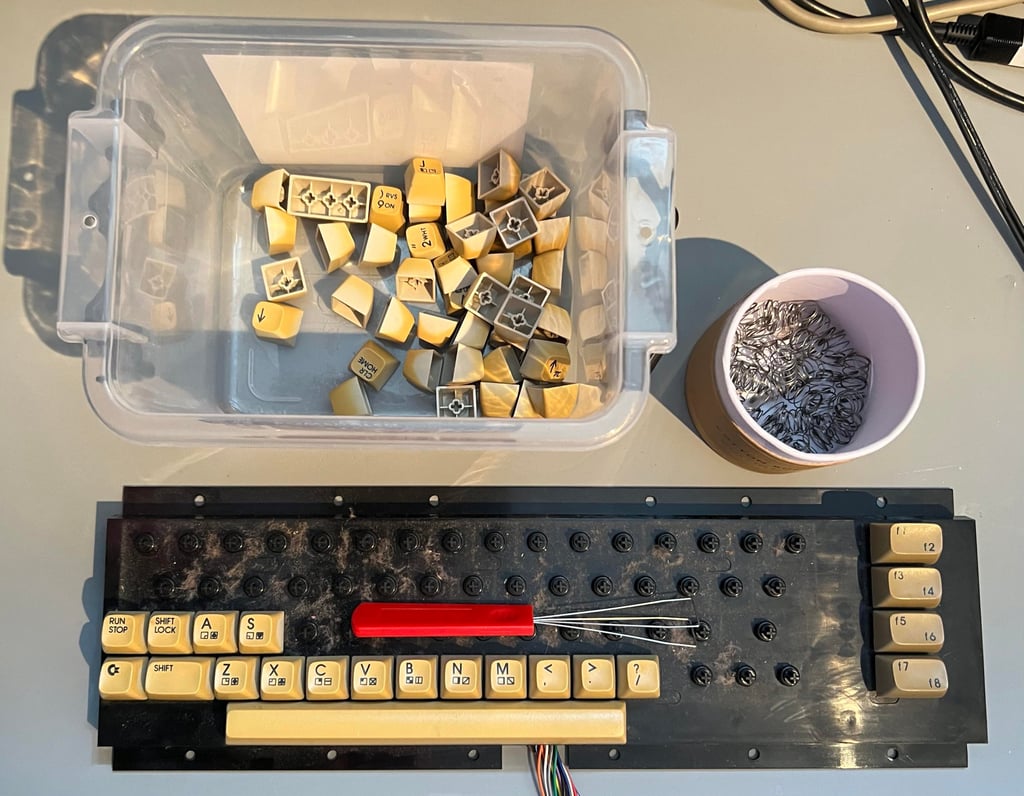
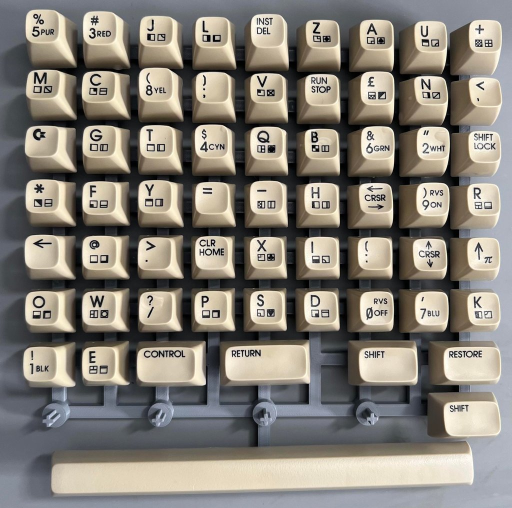
All the keycaps are removed carefully with a keycap puller. None of the keycaps or plungers are damaged during the process. Note that the spring beneath the spacebar is slightly larger than the rest so it is good practice to keep this in a separate bag. There is quite some dust beneath the keycaps, but that is expected.

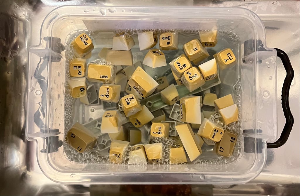
"We all live in a yellow submarine": all the keycaps are soaked in mild soap water for about 48 hours. This will remove most of the fat and grease which is a prerequisite for a successful retrobight.

Next thing to do is to remove the SHIFT-LOCK key. The two unshielded wires are desoldered and then the SHIFT-LOCK is pushed forward from the backside. This will make the SHIFT-LOCK pop out.
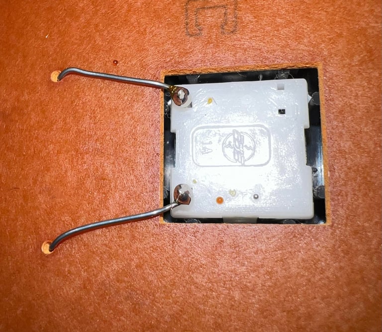
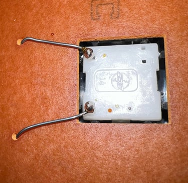
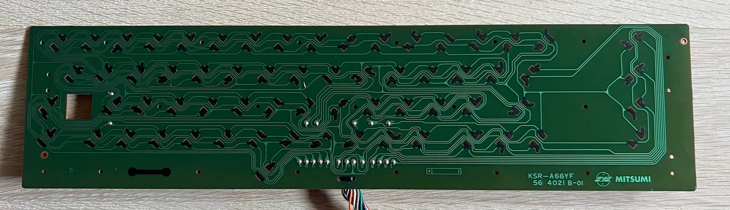
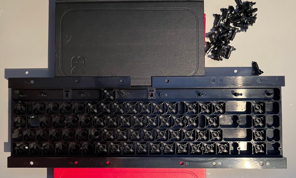
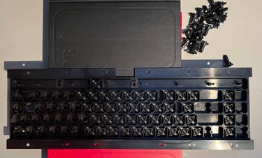
All the 23 tiny screws are removed from the backside of the keyboard. It is not so easy to see from the picture below, but one of the SHIFT-LOCK wires had to be cut as it was too entangled with the switch pin. So a short bodge wire will be put in place when re-assembly.
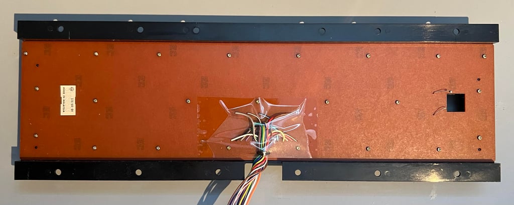

The backside of the keyboard is also the keyboard PCB. This is a Mitsumi KSR-A66YF PCB which is very common in Commodore 64 machines. The keyboard PCB is cleaned carefully with some pure distilled water instead of isopropanol. The reason for this is that the carbon pads can take damage of too much isopropanol.
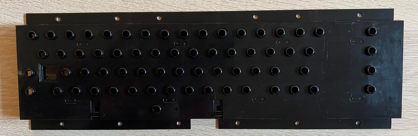
The plastic bracket used to hold all the plungers is cleaned with mild soap water. As can be seen from the picture below the result is very good. The plastic bracket looks as new (!).
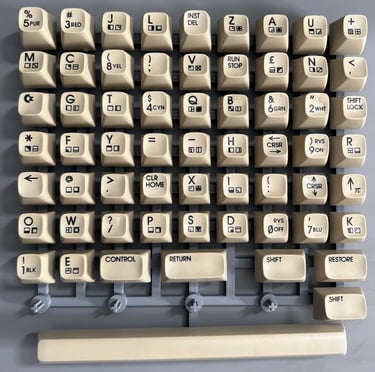
To retrobright the keycaps they are first placed in a plastic bag filled with 12 % hydroperoxide cream for about two weeks. The plastic bag is rotated about once a day. This removes most of the yellowing, but not quite. As can be seen from the picture below the keycaps are now way better than they used to, but still not good enough.
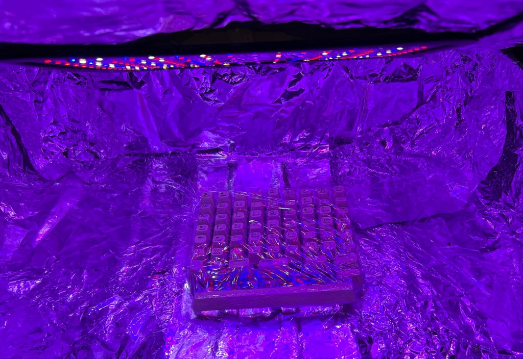
Some last "yellowing exorcism" is required. The keycaps are covered with 12 % hydroperoxide cream, cling wrapped and placed in the UV chamber for about 12 hours. Note that more hydroperoxide cream is added frequently (about every hour) to prevent it from drying out.

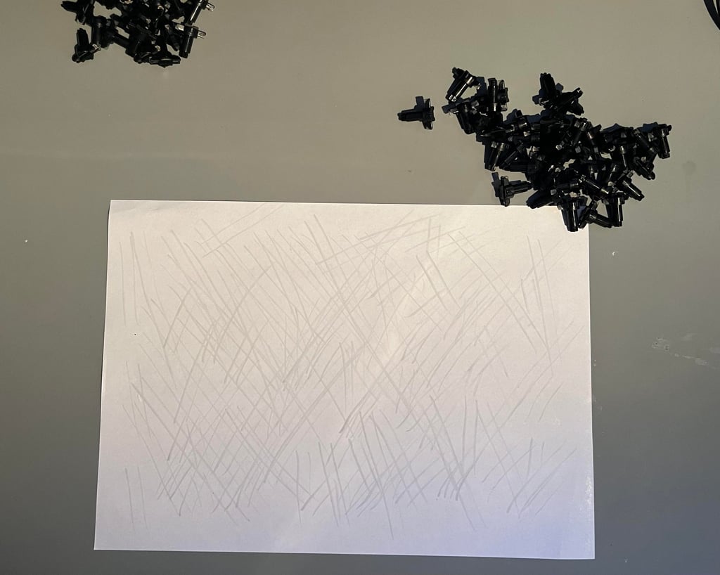
After several years in storage, and use, the plungers are likely to be in need of revival. At the end of each plunger there is a small piece of conductive rubber, and is very common that this conductive rubber is contaminated with dust and grease. This will prevent it from working properly, resulting in keys which needs to be pushed very hard (or hammered) in order to register a key press.
Luckily, this can be fixed most of the times by carefully rubbing the plungers on a clean sheet of paper. Avoid isopropanol if possible as this can deteriorate the conductive rubber, but you can use a small amount if there are very much dirt and grease.

All the revived plungers are put back in the plastic holder. A trick is to use some books to lift the plastic holder slightly to that the plungers can pass through the holes completely.
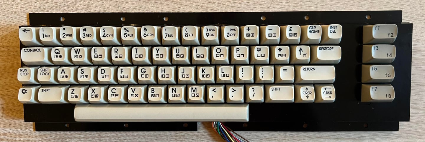
Finally, the PCB is mounted back in, and all the springs and keycaps are installed. The keyboard looks very good!

Mainboard
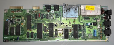
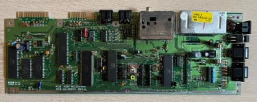
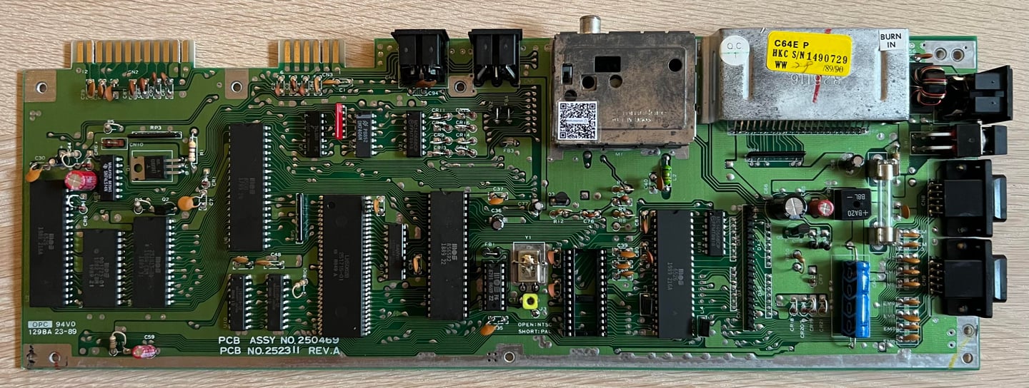
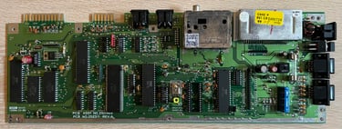
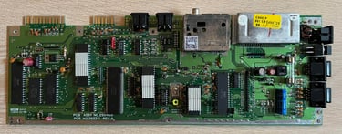
This mainboard is an Assy 250469 / Artwork 252311 (Rev A). Quite a common version of the so called shortboard - equipped with MOS 8580 SID, MOS 8500 CPU, combined Kernal and BASIC ROM, extended PLA (with external Color RAM) and 2 x DRAM chips to mention some highlight.
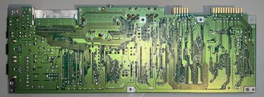
Visual inspection
There is some dust and grease on the mainboard PCBA, but nothing serious. There are no signs of damage, severe corrosion or re-work. Only the VIC-II, clock generator chip (MOS 8701) and SID chip are socketed.
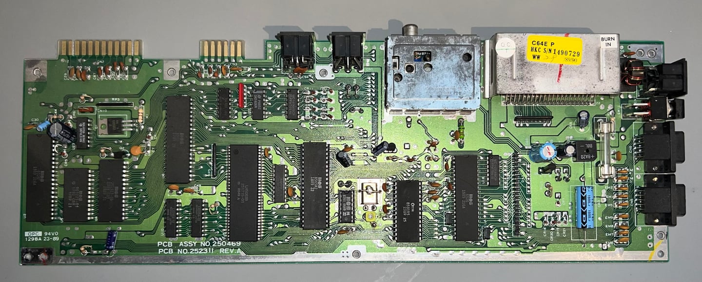

In the table below the custom ICs are listed. As can be seen from the table it is likely that this Commodore 64C was manufactured sometime during the summer of 1989. Quite funny, but the SID chip was produced in the week 23 of 1989, and as it happens it is actually week 23 in 2024 as this is written. So the SID is exactly 35 years old this week! Congratulations!
Initial testing
Before the machine is powered on it is good practice to check for short circuit on the user port (5 V and 9 V rail). And now I notice something which I do not know is normal: when the power switch is in OFF position the 5 V rail is short circuited. Both rails are connected to GROUND. When the power switch is in ON position the short circuit is gone. It should not be a problem that the 5 V rails are both connected to GROUND in OFF position, but I do not know if this is normal or not.
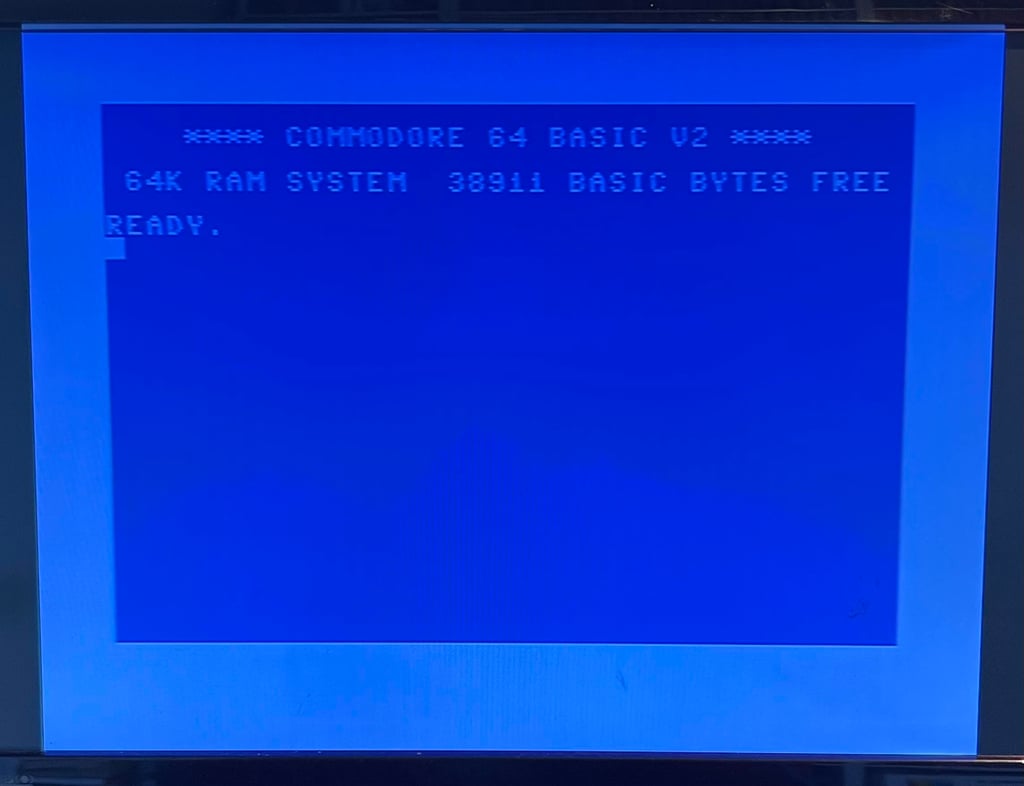
Before powering on the machine the MOS 8580 SID chip is removed with the DIP IC extractor. The SID chip is not required for the Commodore 64 to boot. When the machine is powered on the result is:
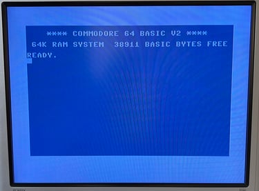
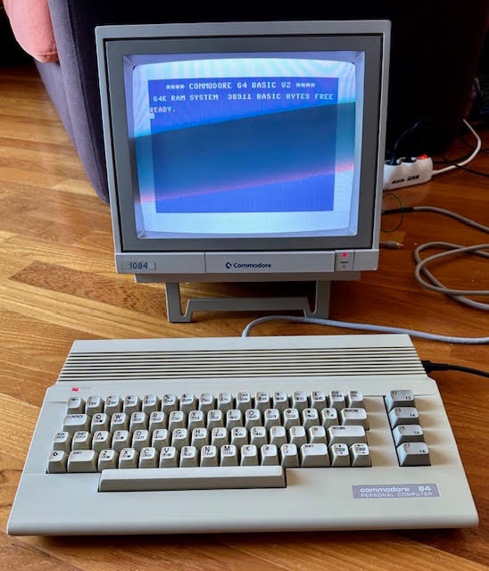
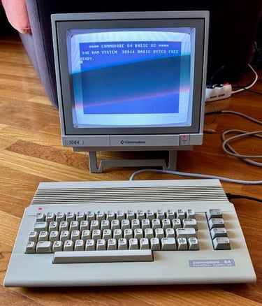
NORMAL BLUE STARTUP SCREEN WITH 38911 BASIC BYTES FREE

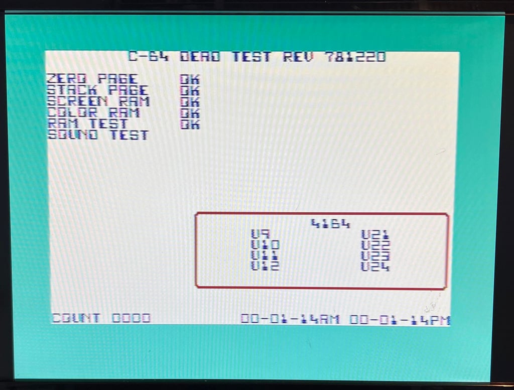
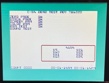
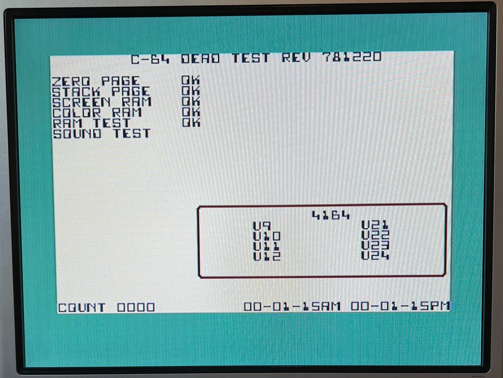
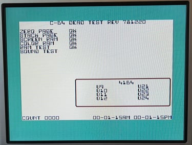
Next, the machine is tested with the Dead Test Cartridge. This will test the basic functionality of the custom chips. At this point the MOS 8580 SID chip is installed again. All tests pass.
Checking the voltages
For the Commodore 64 to work flawlessly all the different voltages need to present and within acceptable tolerances. A detailed article on the subject can be found in the HOWTO - Checking the C64 voltages. In the table below all the measures voltages are listed (this list will also be updated after refurbishment). All the required voltages are present and within tolerances, so there are nothing obvious wrong in that area. NOTE: for those who follow my refurbish project you may notice that many of the voltages appear lower than seen before. The voltages are completely fine, but I am now using a modified C128 PSU which outputs a bit lower voltages - but it is well within tolerances.
Cleaning the mainboard
Although not strictly required the mainboard is throughly cleaned. There is so much dust and grease on the board so it will make the refurbishment process somewhat more pleasent. Cleaning the mainboard is done by using plenty of water, mild dish washer soap and a soft brush. Below is a picture of the mainboard after cleaning (the SID chip is removed during the refurbishment).

Replacing the electrolytic capacitors - Mainboard
There are different opinions on whether to replace the electrolytic capacitors or not. But I think it is good practice to replace them. These capacitors are old (almost 40 years) and they are likely to change their capacitance/ESR during their lifetime. Even though this is not a big problem most of the time you could experience odd behaviour being caused by old capacitors.
According to the capacitor list there are nine electrolytic capacitors on the mainboard. All of them are desoldered without any damage to traces or pads. New capacitors are soldered back in. See picture below of the mainboard with the new capacitors.
Replacing the electrolytic capacitors - RF modulator
As with the mainboard there are electrolytic capacitors in the RF-modulator which should be replaced. But to replace the electrolytic capacitors in the RF-modulator requires the desoldering of the whole modulator container from the mainboard. Desoldering the RF-modulator is not trivial - not that it is very complicated, but it is very easy to damage either mainboard or RF-modulator if you are not careful. A detailed description on how I do this can be found in the HOWTO-article "Desolder the RF-modulator".
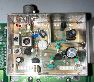
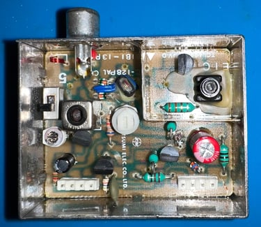
Below is a picture of the RF-modulator before desoldering. This is a RF-modulator from Mitsumi. There are two electrolytic capacitors inside the RF-modulator: 1 x 10 uF [16 V] and 1 x 220 uF [10 V].

The RF-modulator is desoldered without any damage to traces or pads on either mainboard or RF-modulator.
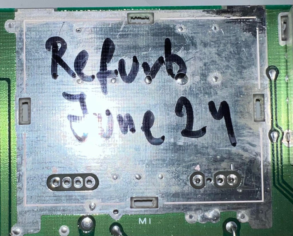

The two electrolytic capacitors are desoldered without any damage, and four new quality capacitors are soldered back in. In the picture below the RF-modulator is shown with the new capacitors in place.

Adding heatsinks on custom ICs
In an attempt to reduce the probability of the custom chips from failing heatsinks are added on the most valuable ICs. Heat will be naturally generated during the operation of the ICs, but too much heat (or the lack of dissipation) can make the IC fail. So modern heatsinks are added to the SID-, CPU- and VIC-II chip. See picture below.

Testing
Proof is in the pudding - does it work?
Testing is done through two main stages:
Testing the basic functionality and chips
Testing by using the machine playing demos, games etc. accessed by both floppy and datasette to verify correct operation
Basic functionality and chips
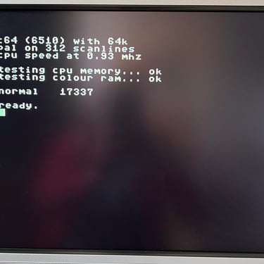
First test is done using the Dead Test Cartridge. This test doesn´t test all the functionality of the Commodore 64, but it does test the basic functionality of the major chips such as the CIA #1/2, CPU, VIC-II, PLA, RAM and SID. As the picture shows below the test is passed.
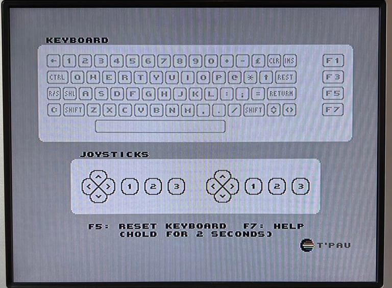
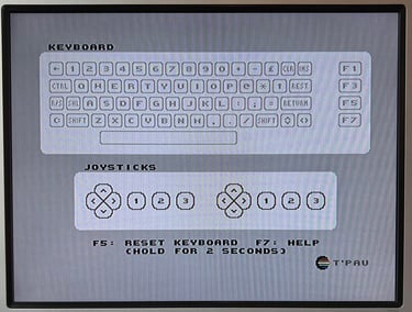
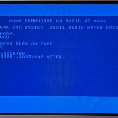
Next test is to power the Commodore 64 to the blue boot up screen and also check the keyboard to make sure all keys works as they should. The test is passed; all keys works and 38911 BASIC Bytes Free.

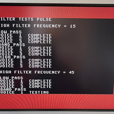
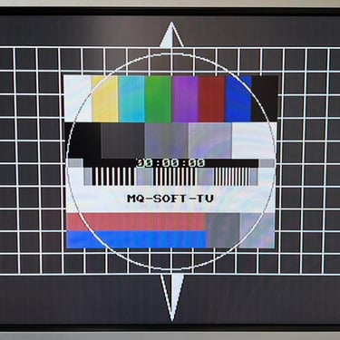
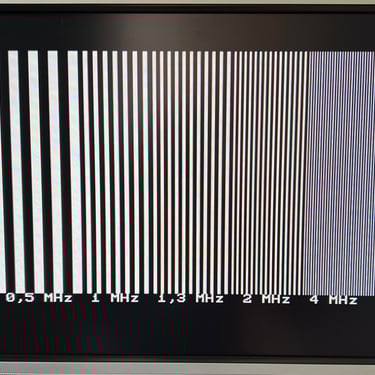
The basic functions of the VIC-II, SID and RAM is tested with 64 Doctor, Commodore 64 SID tester and MemTest64. Note that this is to be considered as basic functionality - more advanced (?) functionality such as sprite handling / collision detection / advanced audio will be tested later. But the basic tests pass without any detected faults (click to enlarge).
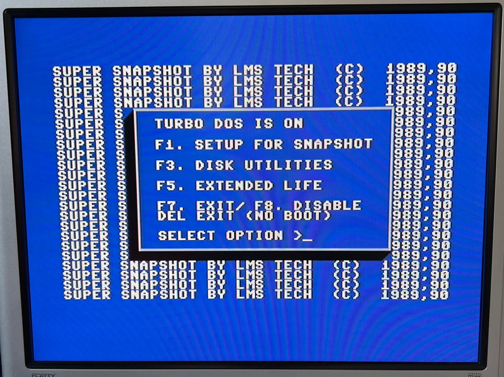
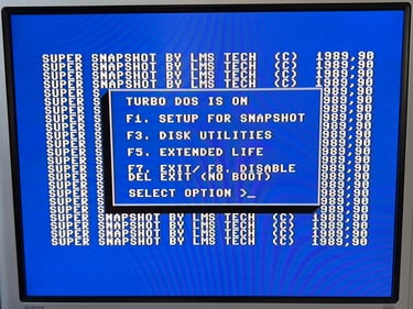
Last basic check before moving to more extensive testing is checking the cartridge. This is done by using the Super Snaphot V. Result is that the test is passed.
Extended testing
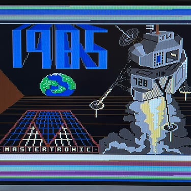
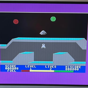
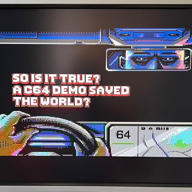
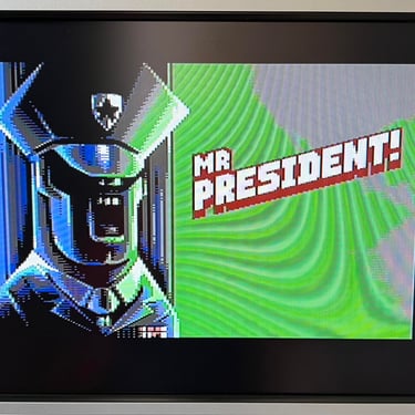
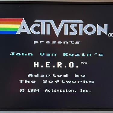
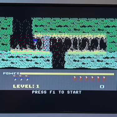
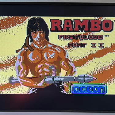
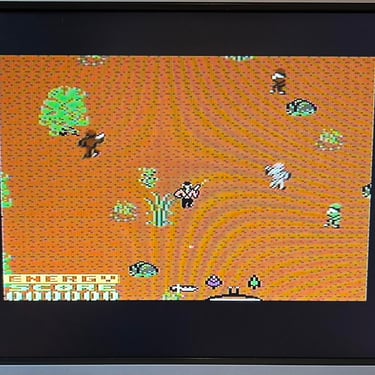
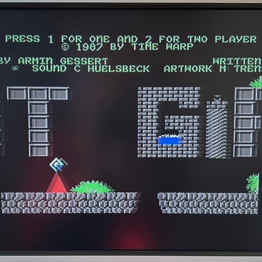
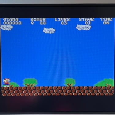
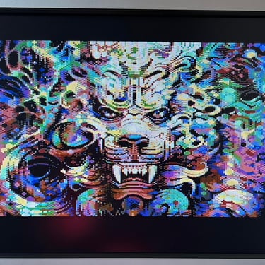
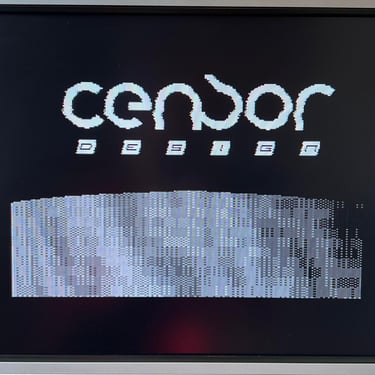
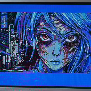
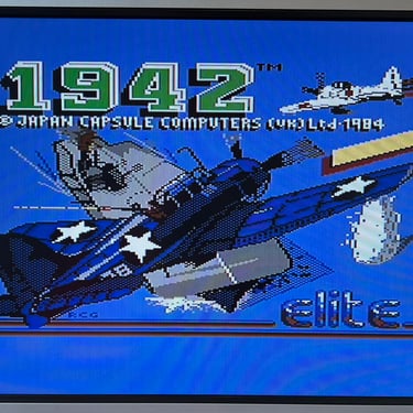
Knowing that the basic functionality of the machine works I continue the testing by using the Commodore 64 for normal operations; playing some games, watching demos, loading from datasette and floppy and using a cartridge. I can not find any issues with this machine. I also pay special attention to the video to make sure that there are no glitches in the graphics - I can´t see any abnormalities. Below is a gallery with pictures from the testing.

Final result
"A picture worth a thousand words"
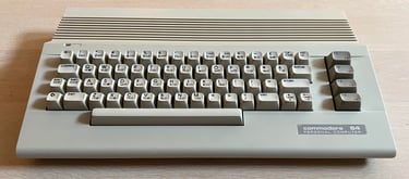
Below is a collection of the final result from the refurbishment of this C64C. Hope you like it! Click to enlarge!
"Are you keeping up with the Commodore? 'Cause the Commodore is keepin up with you!"
Below are some pictures of the Commodore 64C back at the customer´s home!