

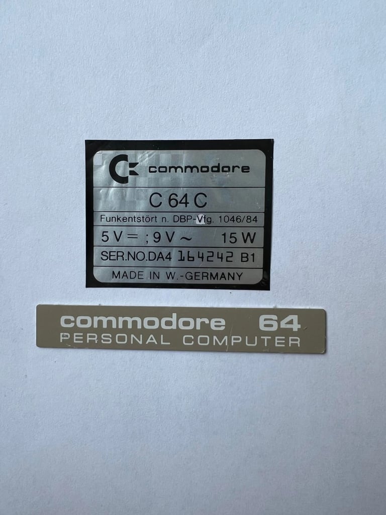
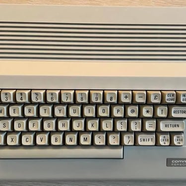
C64C
Ser. No. 164242 Assy 250466
Refurbisment plan
To refurbish this C64C the plan is to do this trough the following steps:
- Clean and restore the keyboard
- Clean and remove stains from the chassis
- Refurbish main board (cleaning, checking, repairing, replacing capacitors etc.)
- Recap RF-modulator
- Add heat sinks on VIC-, SID- and CPU chip
- Verify operation by testing
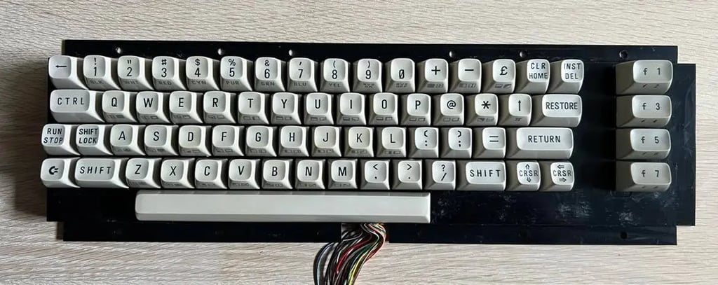
Keyboard
The keyboard is disassembled into the following parts:
- Keycaps
- Springs
- Plastic chassis
- Plungers
- PCB
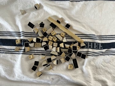
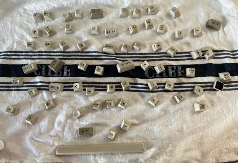
All keycaps are cleaned and rinsed with mild dishwasher soap and left overnight to dry. Some of the keys have some severe yellowing - the plan is to remove some of this by retrobrighting. Picture below (click to enlarge).
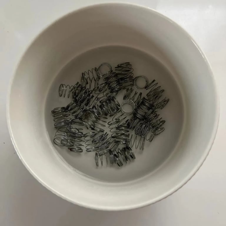
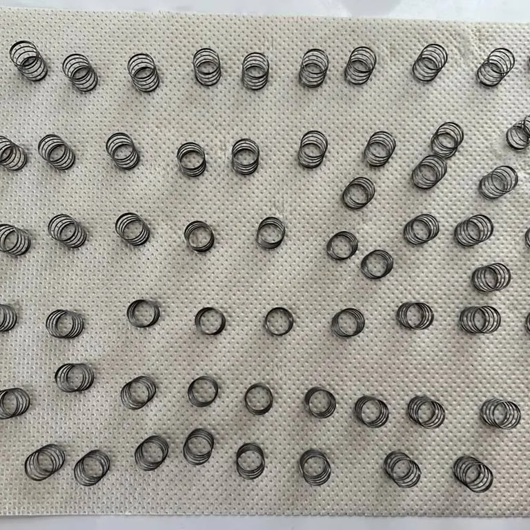
The springs are put in a small bowl with 7 % clear vinegar for about two hours. This is probably not strictly necessary since there are not much rust on these - but I´ll do this anyway to remove any small rust stains. In the left picture you see the springs soaked in vinegar, and in the picture to the right you see the end result (click to enlarge).

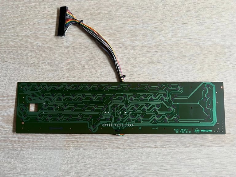
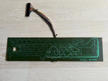
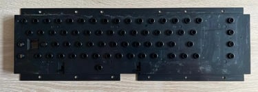
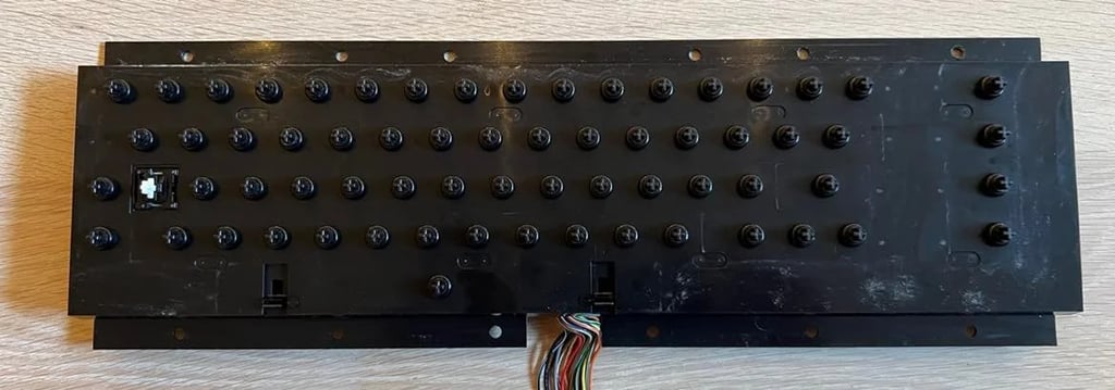
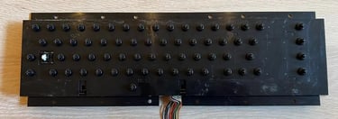
The Keyboard PCB is checked for corrosion and cleaned with isopropanol. No significant corrosion is identified (please note that for old PCBs there will "always" be some corrosion if you look really closely, but this corrosion is to be regarded as marginal). Click to enlarge picture below.
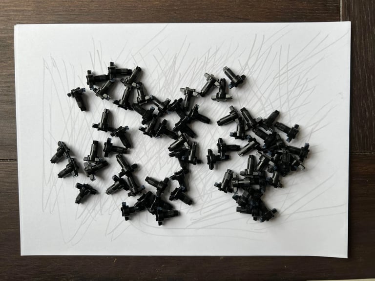
All plungers are revived by gently moving the rubber part over a piece of paper. The plungers are not exposed to any dishwasher og isopropanol. Only gently scratching them on a blank piece of paper. My experience is that this removes any residual dust and revives the contact - the keyboard is works very well afterwards.

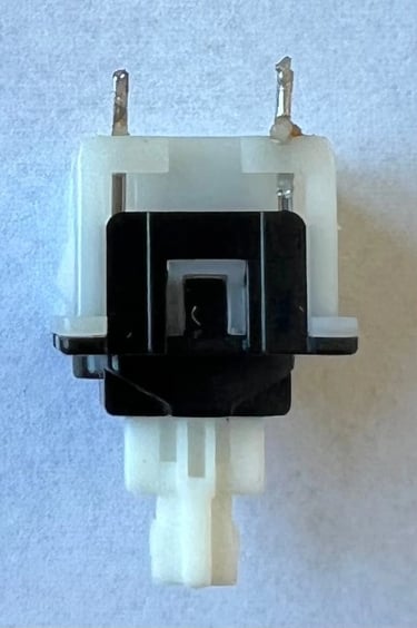
The Shift-Lock key is soldered out from the keyboard and cleaned. Removing the Shift-Lock is very easy; set the soldering iron to 370 degrees Celcius and gently lift off the two wires. Then push the key from the bottom side of the keyboard and the Shift-Lock key should come loose.

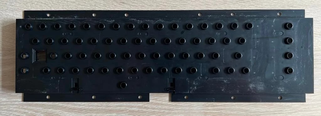
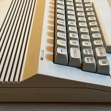
The plastic chassis is cleaned by soaking the whole chassis in luke warm water with mild dishwasher soap for approximately one hour. There are some strange areas with some odd "stuff" which I can´t remove. I really can´t tell what this is - but it does not affect the keyboard in any way. You can see it in the top row of the chassis and bottom right. It could also be something from production - I´ve got no idea...
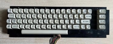
The keyboard chassis assembled with the PCB and the Shift-Lock soldered back in.
After some retrobrighting the keys looks much better. Most of the yellowing are now gone.

And then all keyboard parts are re-assembled - and end result looks like this:
It´s not perfect, but this is as good as it gets with retrobrighting I think. So I´m quite pleased with the end result! Further brighting I think should be done with sunbrighting: the process where only direct, outdoor, sunlight is used. Sunbrighting is a way slower process, but I think that it´s much more gentle process compared with the chemicals used for retrobrighting.
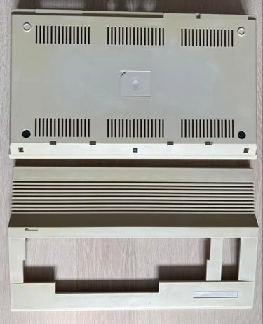
Chassis
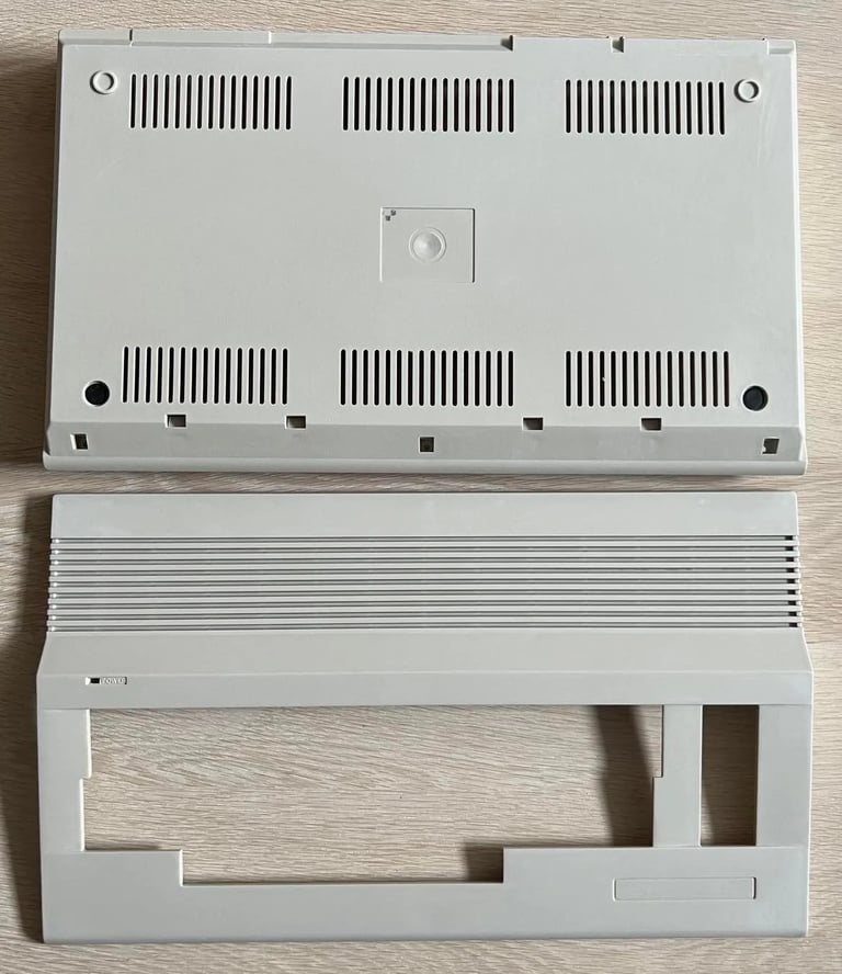
The chassis is disassembled into the following parts:
- Top cover
- Bottom cover
Stickers are removed gently by using heat from a hair dryer and gently pulled off with a sharp knife. Note that during this process some of the metal foil vent missing. This is on the top left corner and also in the "V" in the middle of the sticker. Nevertheless, I think it´s better to loose these than risking that the labels are destroyed in the retrobrighting process. In addition the LED is also removed from the top cover.

The top- and middle cover is soaked in mild dishwasher soap for an hour to remove large fat- and grease stains. Afterwards the cleaning process continue with isopropanol, glass cleaner and baking soda. And no surprise here - the chassis also needs some retrobrighting.
There are some scratches on the chassis which is not possible to remove. Well, you can probably remove some of this by some gentle sanding, but I think it´s better to leave it as it is. Also, note that I´ve removed the two rubber feets on the bottom. This is done by gently removing them with a sharp knife.

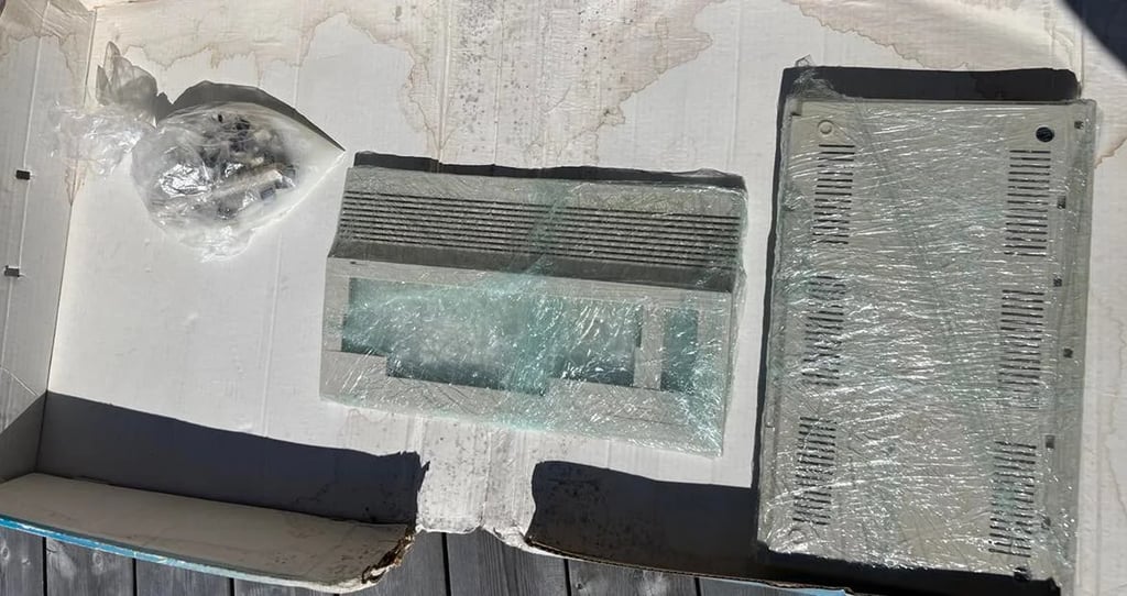
The plan is to retrobright the chassis and the keys. I will use HydroPeroxide cream (https://silverlines.no/produsent/produkt/herfit/oxygenvannstoff-40v-1000ml). The cream is smeared over both top- and bottom cover and wrapped in plastic. The keys are put in a small plastic bag filled with some cream and water. These are left in the sun for 3-4 hours and rotated/massaged every 30th minute. Here´s a picture of the retrobright process:
Most of the yellowing disappeared from the chassis, but it left some streaks/marks unfortunately. This happens when some areas of the chassis dries up during the process. This means that there is not enough cream beneath the plastic in some areas.
Now, what to do then? Since there already are some marks/scars on the chassis I decide to gently sand it with some P180 paper and some P1000 wet sanding. This was not what I hoped for, but this is the game of refurbishment: this WILL go wrong - but find the best solution to move forward! Still, I think the end result is quite ok!

Main board
Assy 250566 is my favorite main board - no doubt! This is the same assy that I use in own C64 if that matters. There are two main reasons for this:
1) This is the latest revision of PCB with the "old" SID chip .This is the MOS6581R4AR version of the chip where R4 means revision 4 and AR stands for "Advanced Resonance". So, even if the "new" SID chip is good there is just something with the "old" one...
2) This version contains the VIC-II chip MOS6569R5. This version of the VIC-II chip is acclaimed for showing very few artifacts such as vertical lines and checkerboard patterns).
In this C64C the SID chip is produced in week 49 in 1986 and the VIC-II chip is produced in week 47 in 1986.
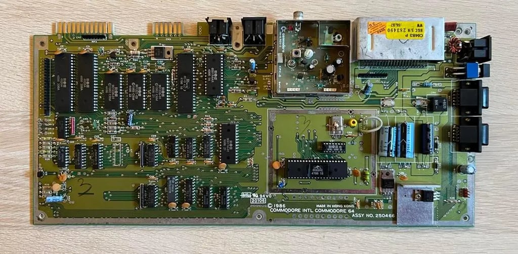
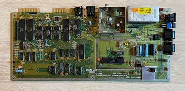
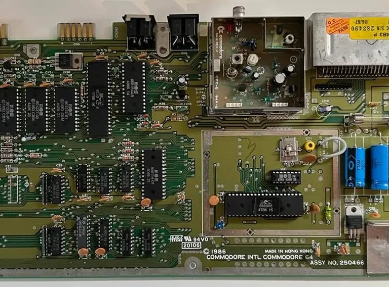
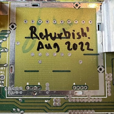
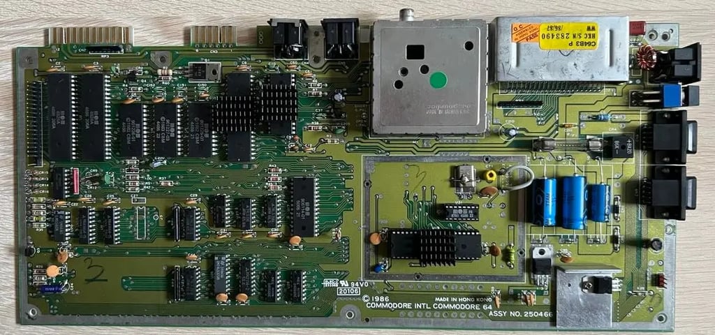
Below is a picture of the front of the PCB before any refurbishment. Please note that the fuse is missing, but ALSO notice that NO chips are socketed (except for ths 6581 SID which is socketed from factory). I can´t guarantee it, but to me it looks like NO ONE has ever done any major repair on this board previously! Holy moly!
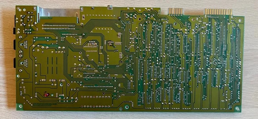
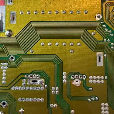
And here´s the backside of the PCB. As far as I can see no re-work has been done...

Now, let´s see if the main board works. I install a known working 250 V / 1.6 A fuse, and do a quick check to see if there is a short between GND and 5V og 12V on the 7805/7812 voltage regulators. No issues there so I think it´s safe to turn on and try the board. And lo and behold - it works! The magnificent good old blue C64 screen is displayed!
Or wait... No... there is something odd going on. Sometimes when I turn it on and off it will not start. Completely dead - no image and no power. I think there is something wrong with the power circuit and it could very well be just a bad solder joint either in the power intake or that the on/off switch is bad. It could also be a marginal voltage regulator I guess. So my plan is now to visual inspect the power intake and on/off switch and resolder all the points connecting these to the main board. In addition I will replace the old voltage regulators (7805/7812) with new ones.
I measure and record the voltages (when the main board is ok) - see table below. I measure both the voltage regulators and the user port. Note that I measure these voltages both with the old and the new 78xx voltage regulators.
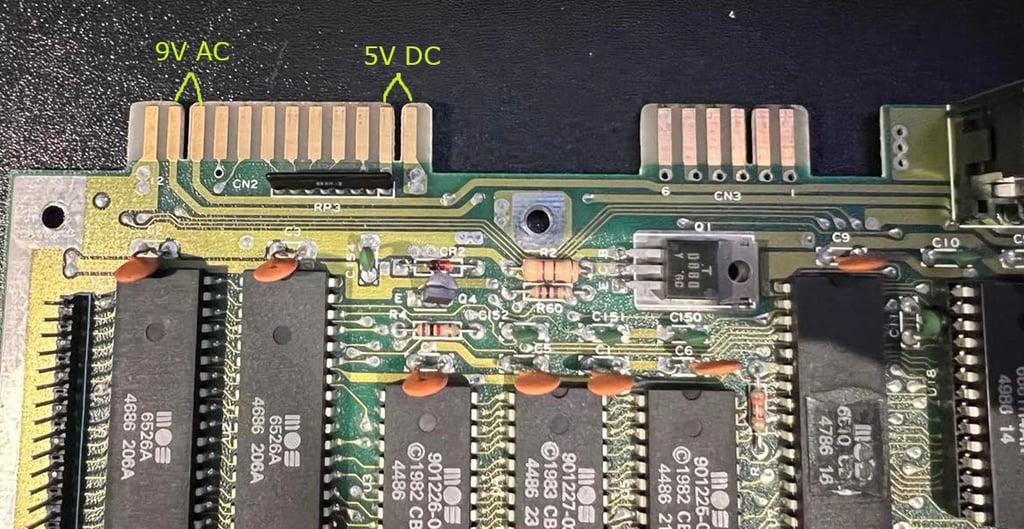
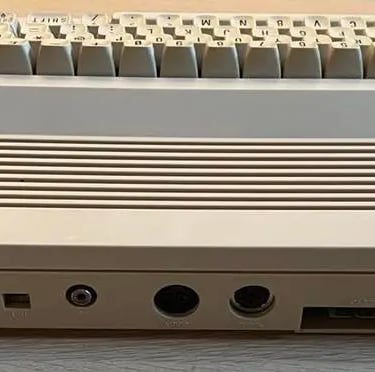
To measure the 9V (AC) and 5V (DC) voltages on the User Port you find these between the two notches on the top left of the main board.

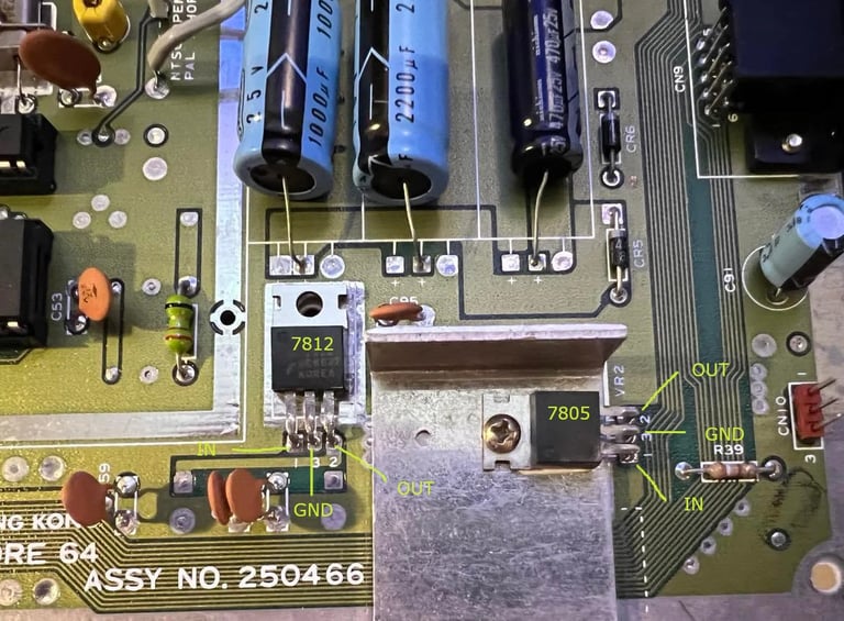
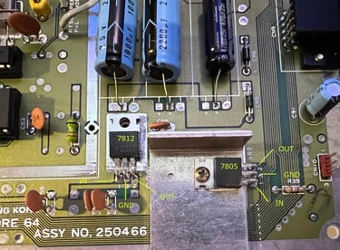
To measure the 5V (DC) and 12V (AC) voltages on the 7805 and 7812 respectively you find these on the bottom right of the keyboard (on this assy).
About voltages:
There are four voltages which are important for the C64 to operate correctly. These are:
- 9V AC
- 5V DC
- 5V DC (CAN)
- 12V DC
The first two, 9V AC and 5V DC, are generated directly from the external PSU. The 9V AC is used as input for the 7805 and 7812 voltage generators, and the 5V DC is used to power all the chips on the motherboard - except for the VIC-II chip. You´ve maybe heard that the C64 PSU can damage your chips. The reason for this is that the 5V voltage regulator that is in the PSU can start to drift. And if so happens the voltage can get above the 5V tolerance with the result that some of the chips on the mainboard can be destroyed. Note: the 9V AC from the PSU does not have this problem. The 9V AC is transformed from 110/220V AC to 9V AC without any regulation in the PSU itself. So this is why it´s highly recommended to get a new PSU for your Commodore 64.
The 5V DC (CAN) and the 12 V DC are generated by the 7805 and 7812 voltage regulators respectively. The input for both of these stem from the 9V AC (rectified). The 5V DC (CAN) is used for the VIC-II and the 12V DC is used for the SID chip.
The schematics of this assy can be found at Zimmers (these scans are quite hard to read):
http://www.zimmers.net/anonftp/pub/cbm/schematics/computers/c64/252278-1.gif
http://www.zimmers.net/anonftp/pub/cbm/schematics/computers/c64/252278-2.gif
Next step is to order new voltage regulators, a new fuse and new electrolytic capacitors. I get all this from Phil at Retroleum (you'll find the link in the online resources page as well) - https://www.retroleum.co.uk
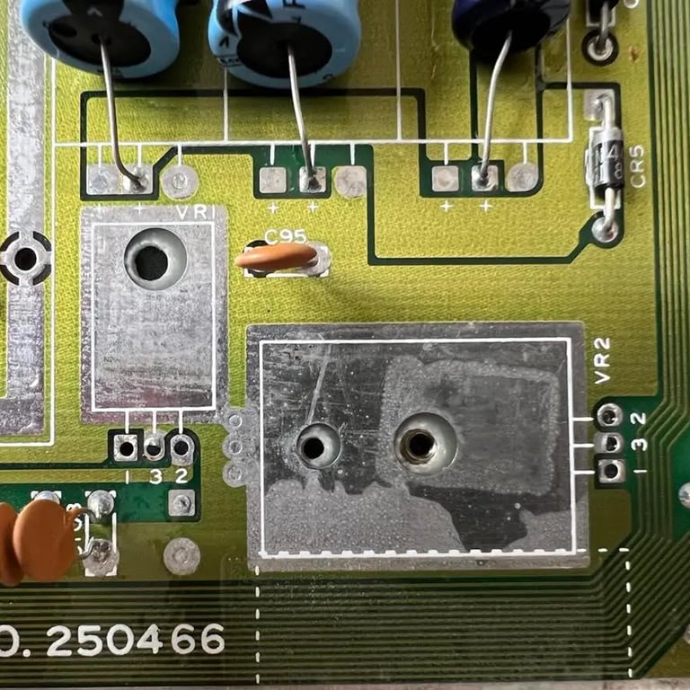
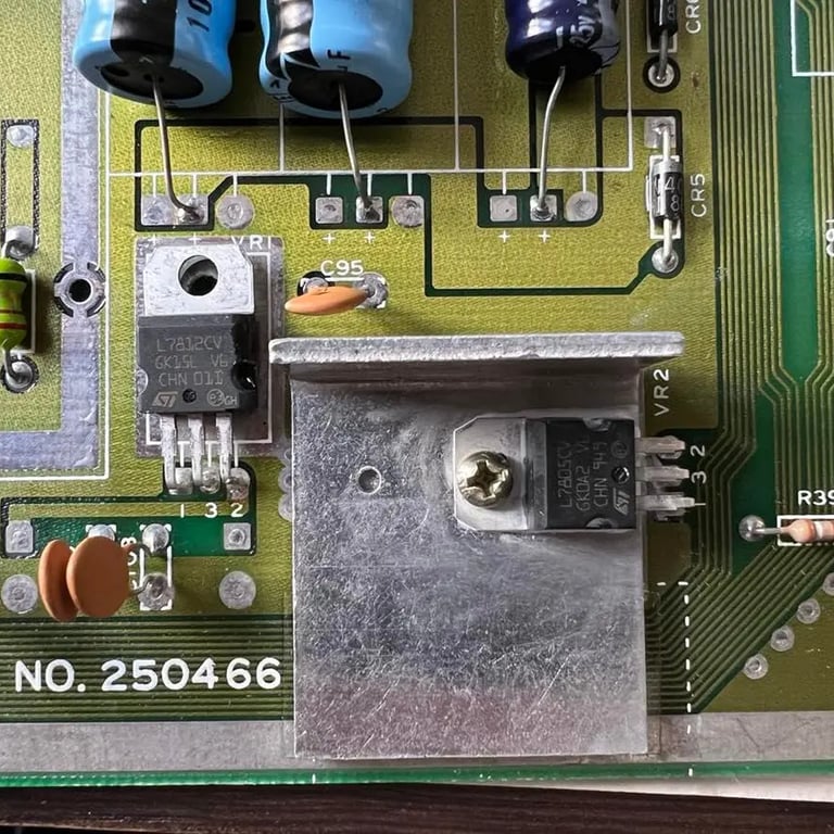
Now I´ve received a new fuse, new voltage regulators and new capacitors for the main board. The fuse and the 7805/7812 are now replaced. Note: there are no screw/nut for the 7812 regulator, but this is by design. The 7805 do have this as it¨s connected to a heat sink. Also, some heat paste is placed under the 7805 regulator so it looks a bit dirty, but this is normal. See pictures below (click to enlarge). After the new fuse and the regulators are in place the voltages are measured again.
I resolder all points to the main switch also. I can't see any obvious faults here - and I've experienced a few times before that these switches are just a bit "rusty" due to a long time not being used. I switch it on/off several times (without power) and clean with contact cleaner.
After verifying that the main boards stills boots to the default blue C64 screen, all the electrolytic capacitors on the main board are replaced. There are eight of these - see pictures below (click to enlarge). Note that the electrolytic capacitors in the RF-module will also be replaced at a later stage.
RF Modulator
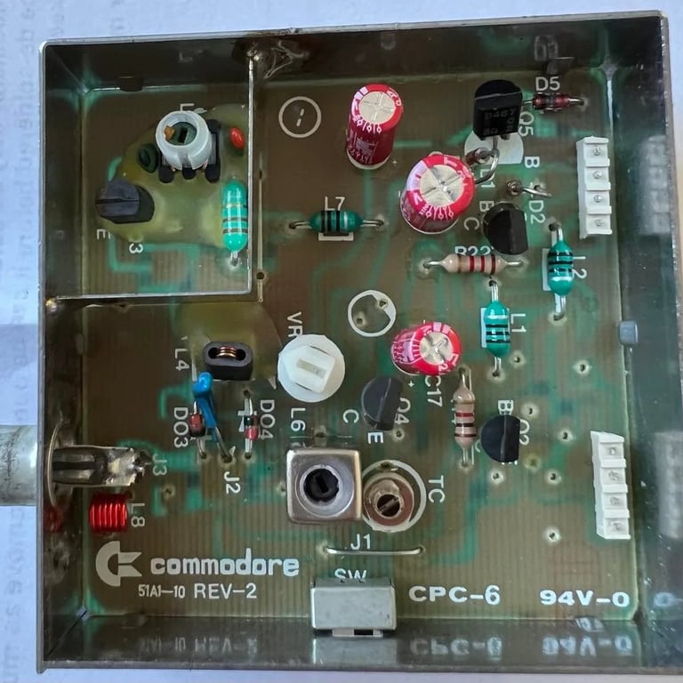
The RF modulator contains three electrolytic capacitors that needs to be replaced. But, to do this the RF-modulator needs to be desoldered which is not trivial. When I desolder the RF-modulator I make sure that I can do it without any hurry.
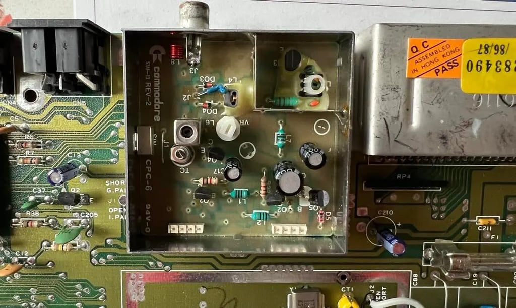
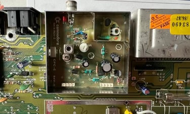
It's not that's impossible to desolder the RF-modulator, but you need to be very careful so you don't lift any pads and/or traces. To remove the RF-modulator I do this the following way (see picture below for details):
1) Carefulle twist the four "locks" with needle nose pliers. It's important that they are positioned so that they are not blocking anything when the RF-modulator will be lifted off. Sometimes these are also soldered onto the board which makes it even harder...
2) There are three large points soldered onto the PCB. These three points are an integral part of the RF-modulator metal shield. To desolder these I first add some fresh solder and then use solder wick. Note that I need to set the temperature of the solder iron to a very high temperature (approximately 450 degrees) to get enough heat to get the desoldering going.
3) There are eight pins connected to the PCB (see point 3 in the picture). The pins 1-4 are used as input to the RF-modulator and the pins 5-8 are output. So that means that the raw video signal from the VIC-II enters the modulator and then get mixed to signals that can be used for TV-sets. Note that these eight pins are in turn connected to a second PCB within the RF-modulator chassis. To desolder these eight pins I use the desoldering station.
Now, with everything desoldered it's just easy removal of the chassis? Oh no... these RF-modulators tend to be quite hard to remove without damaging the pads/traces. So the way I do this first to gently move/push the eight pins with the needle nose pliers. I make sure that none are stuck to the PCB. But I need to be careful not to brake anything.
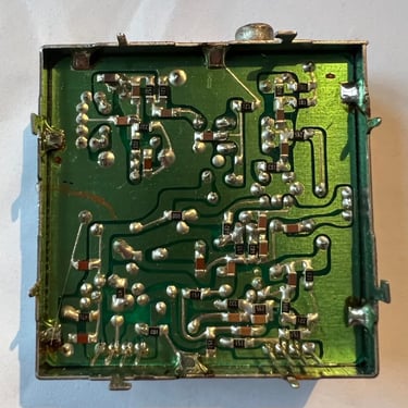
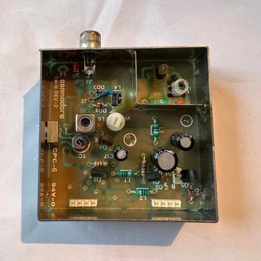
Then I gently push a small screw between RF-modulator chassis and PCB while I use hot air in circular motion on the backside and frontend of the PCB. When I do this carefully I feel that the RF-modulator loosens bit by bit. I move the screw driver to different positions between the PCB and RF-modulator chassis and repeat the operation. After a while the RF-modulator is loose, and all points are cleaned up. See pictures below (click to enlarge).
After the cleanup with isopropanol I check connectivity of all the eight pins. This is very easy to do with a multimeter - and VERY valuable. Because if you see that some of the traces/pads were broken during the desoldering process it's easy to fix this now with some bodge wire - before the RF-modulator is replaced.
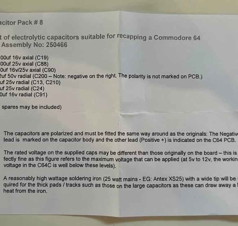
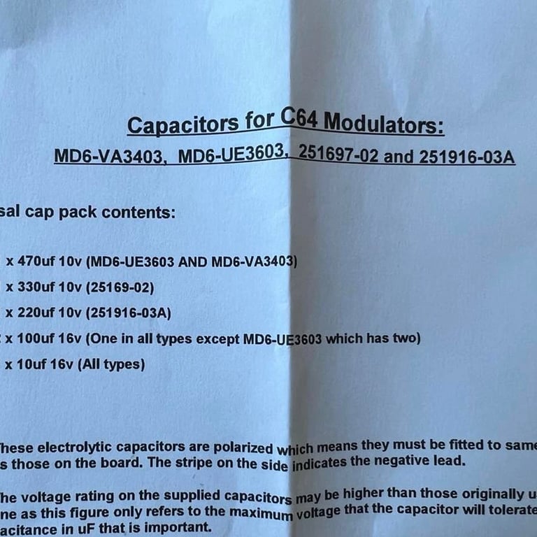
Now, with the RF-modulator off the PCB it's time to recap! I've ordered new electrolytic capacitors from https://www.retroleum.co.uk/
In this RF-modulator there are only three electrolytic capacitors; 10 uF, 100 uF and 330 uF which all have a 10 V rating. Recapping the modulator is quite straitforward, but please take notice that the 330 uF capacitor is placed between two SMD resistors mounted on the backside of the PCB. So when desoldering / soldering I need to be careful not to move any of these while changing this capacitor.
With the new capacitors in place the RF-modulator is soldered back into the main board. At this stage I do a short test to make sure the C64 main board produce the good old blue screen - which is does.
Heat sinks
Do you really need heat sinks? Well, I do beleive that heat sink can increase the probability of longer durability. Some of these chips can get really hot - the VIC-II, SID and the CPU.

Testing
Now the fun part starts - if everything works that is!
I do the testing in two stages when the C64 is completely assembled:
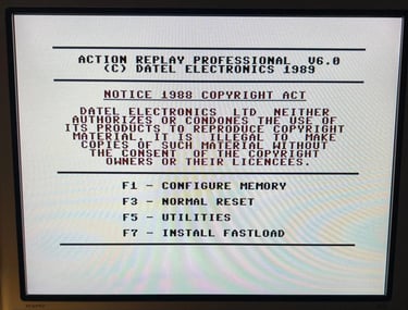
1) With the Dead test cartridge
2) With the Ultimate II+ cartridge
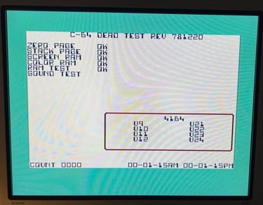
The Dead test cartridge is important because it checks the most important C64 chips (PLA, SID, CIA 1/2, CPU and VIC). And also, if there are problems this cartridge is often a good starting point for fault finding.
But when testing with the Dead Test with this C64C everythings works ok:

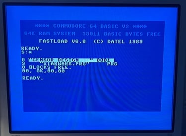
The next stage is to the test with the Ultimate II+ cartridge. I don't have the harness for the Diagnostic Cartridge to do a quick test so instead I do it the "hard way":
- Test floppy access
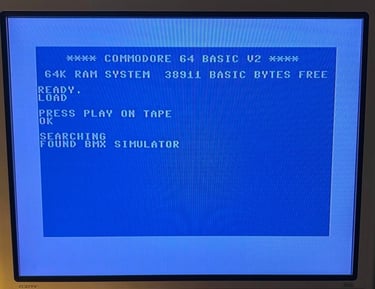
- Test loading from datasette
- Test cartridge
- Check audio/video/keyboard/joystick operation
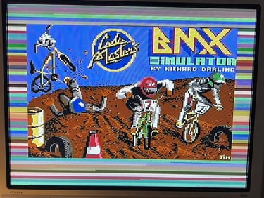
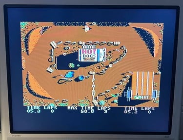
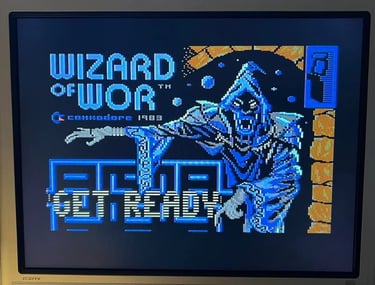
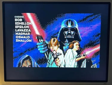
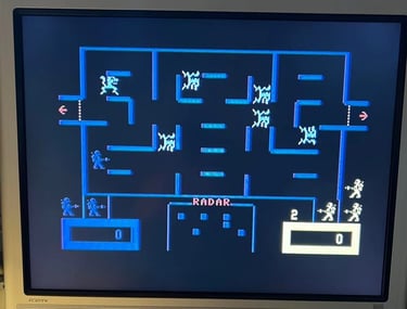
As far as I can see everything works fine. I play several games and watch demos for several hours - both for testing but also for some great fun!
I've also switched the machine on/off for several times without any problem.
Below you will find a few screenshots from the testing (click to enlarge).

Final result
"A picture worth a thousand words".
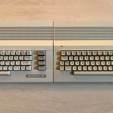
Below is a collection of the final result from the refurbishment of this C64C. Hope you like it! Click to enlarge!
Note that in one of the pictures I compare the color of the C64C chassis to my own C64C. The machine to the right my own, and the one to the left is this one
Banner picture credits: MOS6502