

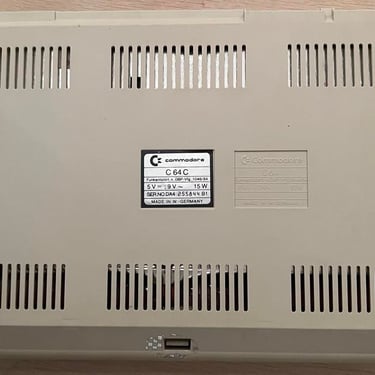
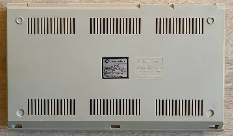
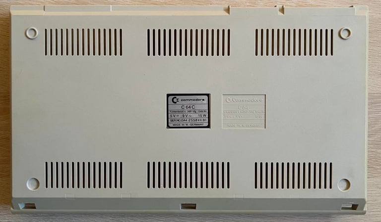
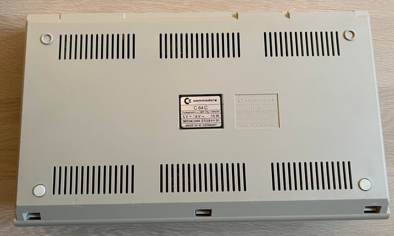
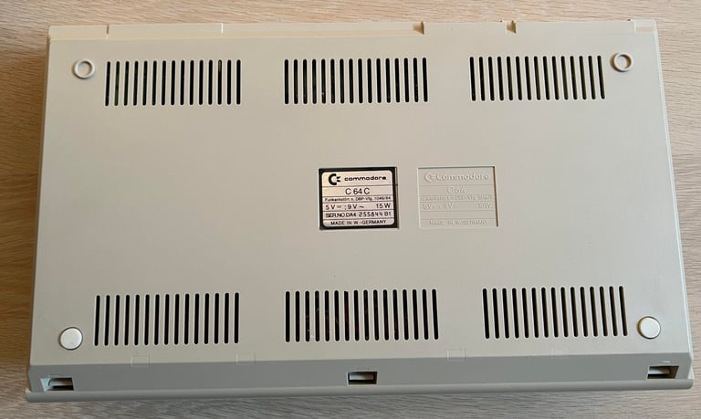
C64C
Ser. No. 255844
Assy 250407
Artwork 251137 (REV C)
Starting point
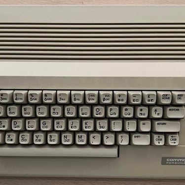
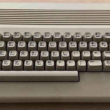
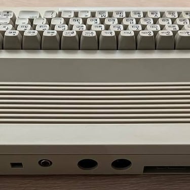
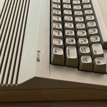
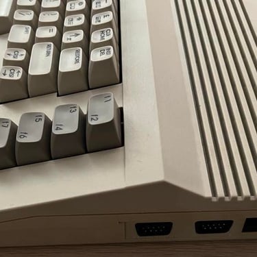
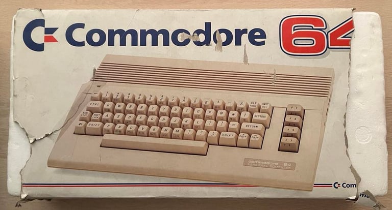
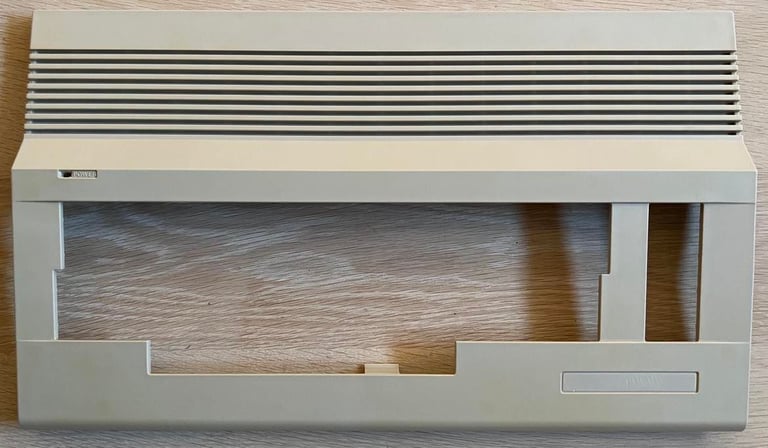
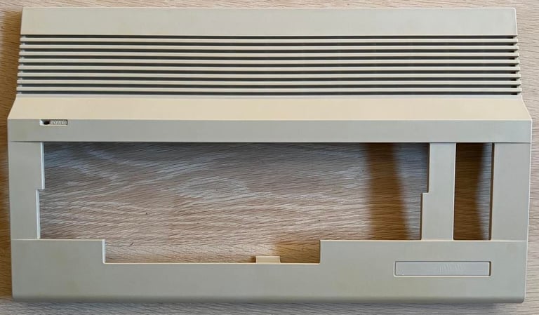
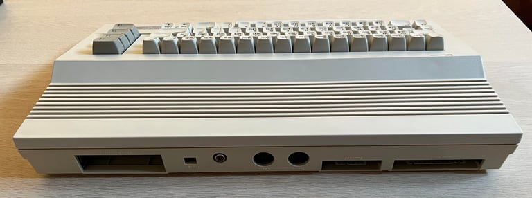
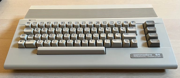
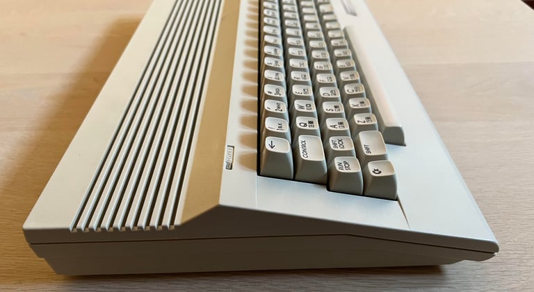
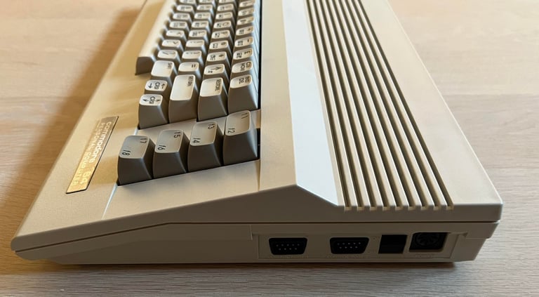
"Image is everything!" - By the looks of this C64C it´s just to power on and your are right back to the end of the 80´s! It´s quite clean and looks undamaged from the outside.
But I have no idea if this works or not - that will be discovered later!
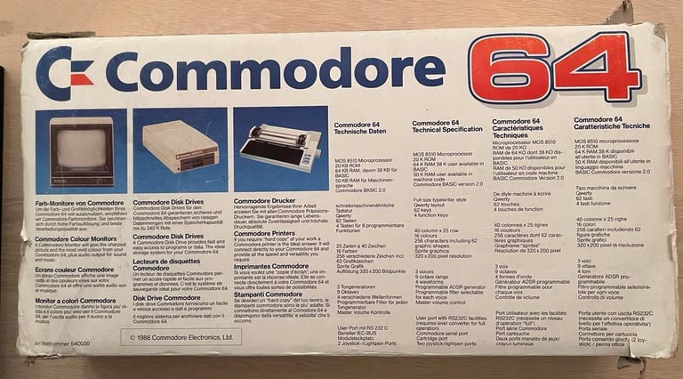
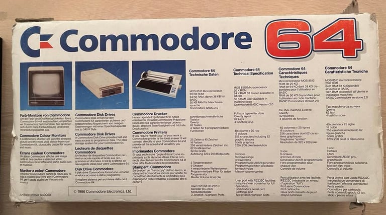
Below are some pictures of the C64C before the refurbishment begins. Notice that the original cardboard box is also there.
Refurbishment plan
To refurbish this C64C the plan is to do this trough the following steps (some of them in parallell):
Clean and remove stains from the exterior casing
Clean and restore the keyboard
Refurbish main board (cleaning, checking, repairing, replacing capacitors and voltage regulators, adding heat sinks etc.)
Recap RF-modulator
Verify operation by testing
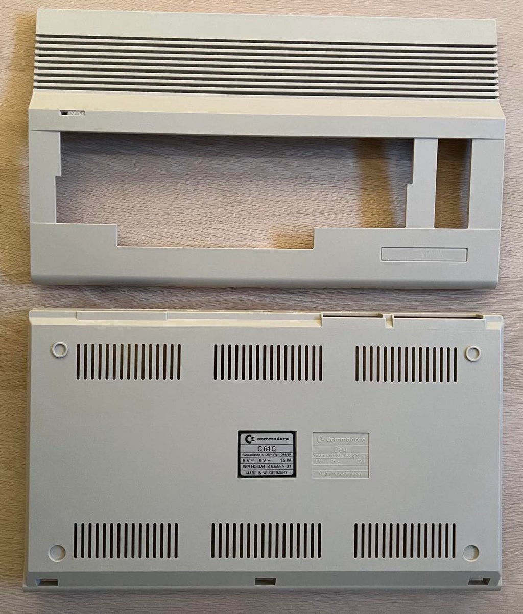
Exterior casing
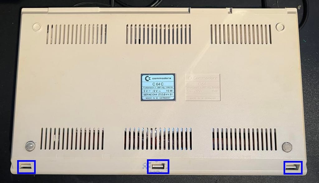
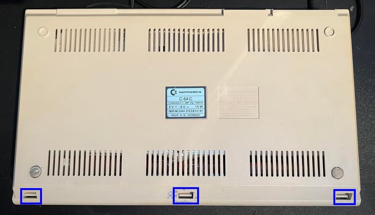
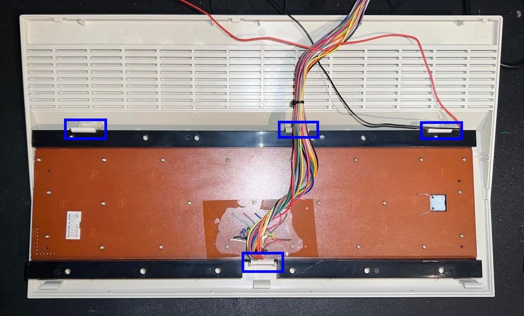
The exterior casing consists of two main parts; the top- and the bottom cover. These two covers are connected by some plastic brackets/clips at the back and at the front. To separate the two parts the three plastic clips in has to be pushed gently in order to release the two covers apart. The location of these three clips are shown in the picture below (blue rectangular areas).
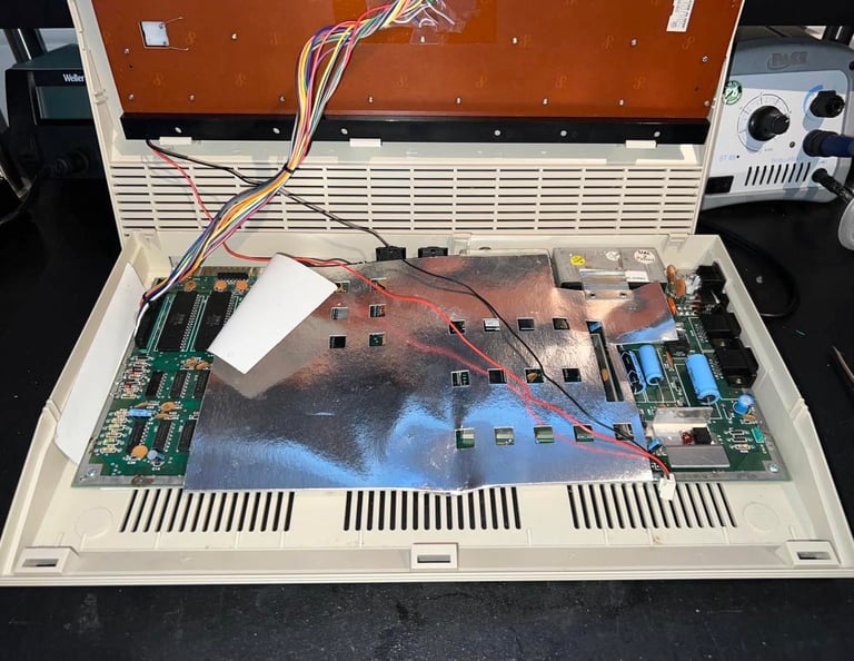
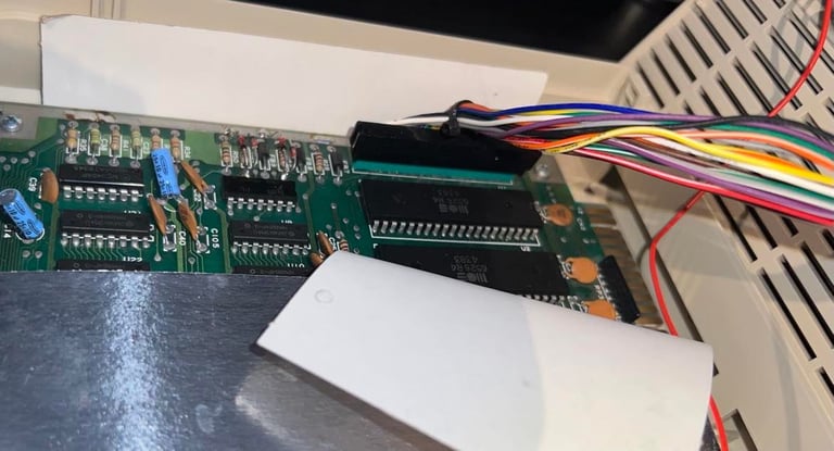
When opening the machine I notice that the LED wire is disconnected, but that is fine since I´m going to remove this anyway. But what I also notice is that this is not the short mainboard which I was expecting. It is the long mainboard version. These "modern" C64C are as far as I know equipped with short mainboards, but the bottom cover is made to handle both versions (screw brackets etc.). Maybe the mainboard has been replaced at some time?

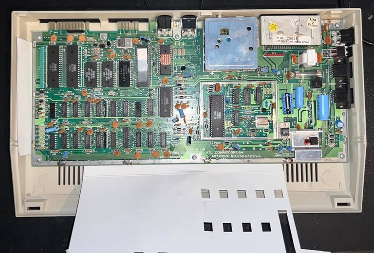
Next is to remove the keyboard connector. This is usually a walk in the park, but sometimes you need to wiggle it a bit to come off. When re-inserting the connector later it is wise to spray some contact cleaner both on the pins on the PCB and in the keyboard connector. Below is a picture of the connector, and of the mainboard which is now revealed in all its glory.
To remove the keyboard from the top cover it is only a matter of gently pushing away the four plastic clips holding it in place. Nevertheless, keep it mind that this plastic is old, and can be brittle, so it is wise to be gentle when pushing these to avoid breaking any of them. Picture below show the position of these four plastic clips (blue squared).

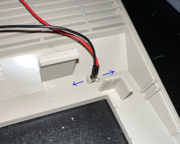
I also remove the LED before cleaning. It is not strictly required, but I like to get the most out of the way to prevent anything from breaking during cleaning. To remove the LED I carefully push the small plastic clip "wings" away to make space for the LED to come out. Again, plastic is brittle, so it is wise to be careful.
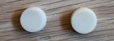
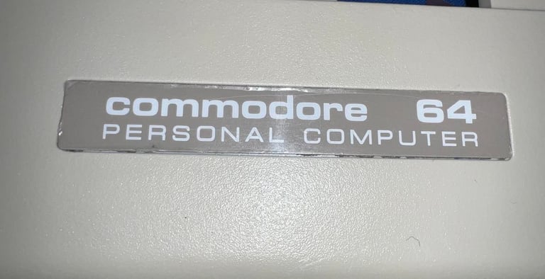
The badge of the top cover is removed by applying some heat from a hair dryer, and carefully using a sharp knife prying the badge off. I also try to remove the sticker from the bottom cover, but I choose to stop since I see that it will not come off without damage. I take the risk that this sticker will survive cleaning (and maybe retrobright). Is the plastic protection still on the badge?! I think so, but I´m not 100% sure. Rubber feets are also cleaned.
Top- and bottom cover is first cleaned with mild soap water and a paint brush. I´ve found out that a paint brush - instead of a normal dish brush - is the best tool for cleaning. Stains are removed with glass cleaning spray, isopropanol and some baking soda on a Q-tip. The result of the cleaning is shown in the pictures below.
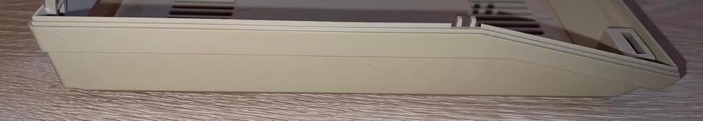
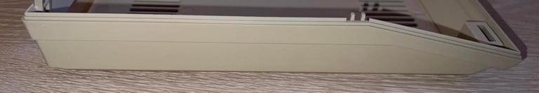
Even if most of the exterior casing looks quite good, there are some areas which shows sign of yellowing. Areas such as the sides and part of the front is a bit yellow. It is not so easy to detect as first, but on the side there is a circular area where a sticker probably has been shows it good. So some retrobrighting is required.

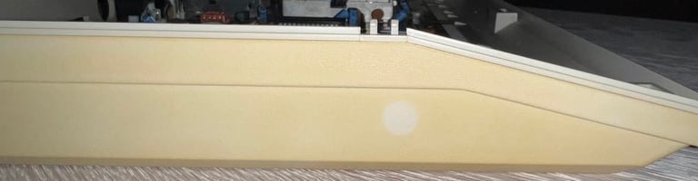
The top- and bottom cover is retrobrighted with UV-light while continuously applying 12 % hydroperoxide cream for about 10 hours. The result is very good I think. Below is a picture of the side (to be compared with the picture above) and a picture of both covers after retrobrighting.

When I put back the Commodore 64 badge I notice something: I think that the plastic foil is still on(?). I am not really sure but it looks like it is still in place. I leave it to the new owner to decide wether to remove it or not.

Keyboard
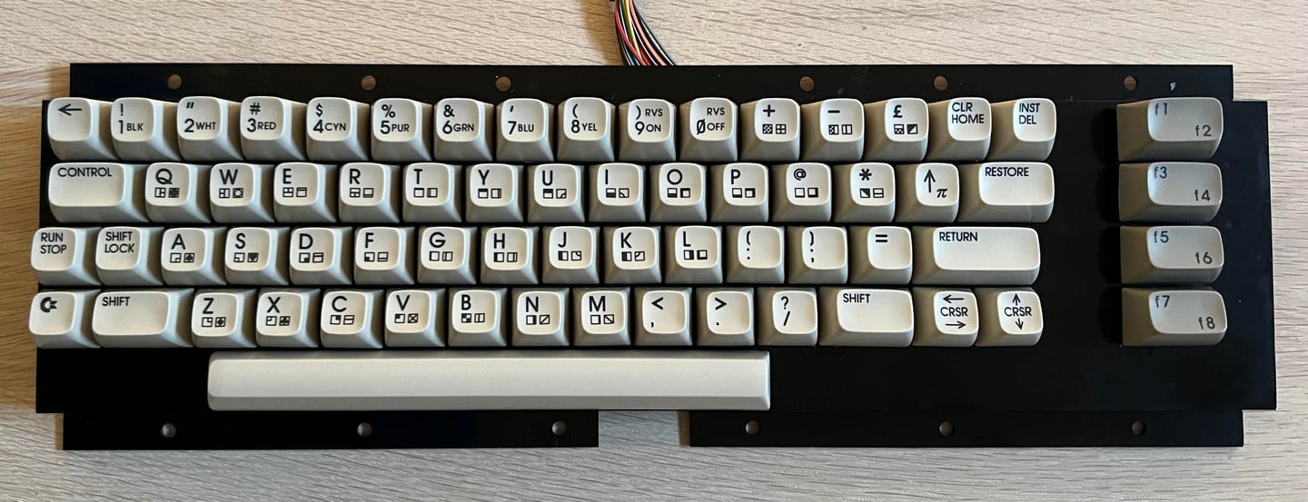
The keyboard looks quite nice. I can see some dust behind the keycaps, but it looks and feels good. The plan is to clean it thoroughly and retrobright the keys.
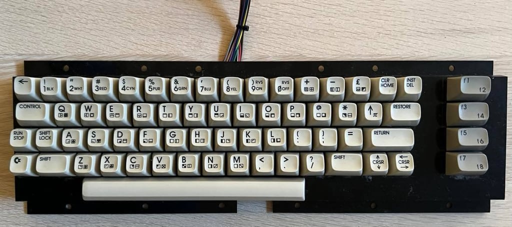
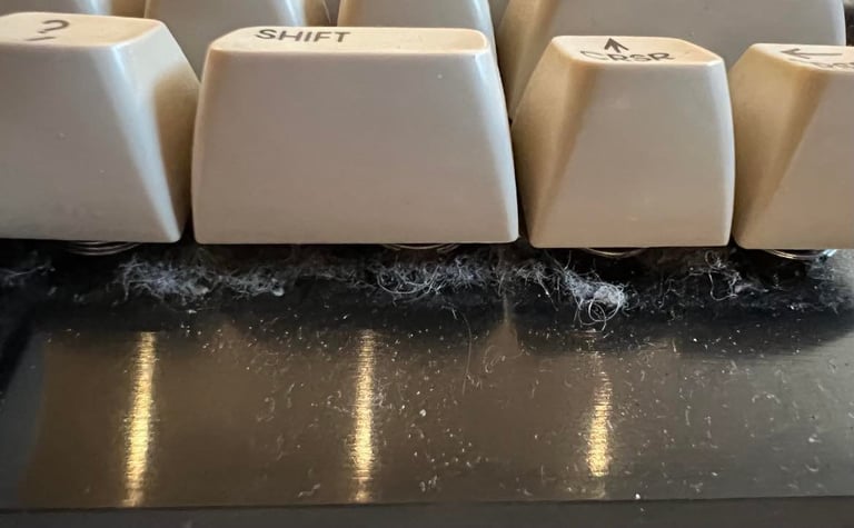
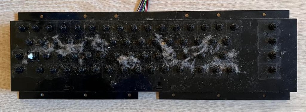
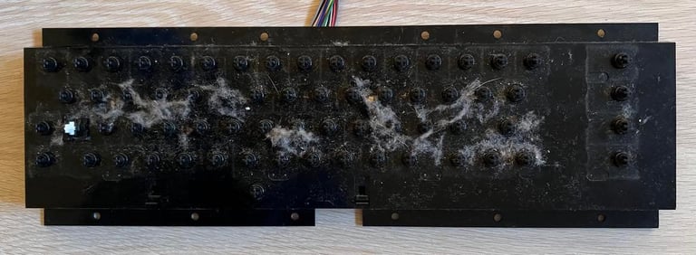
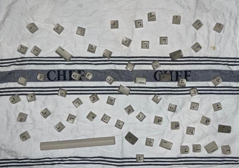
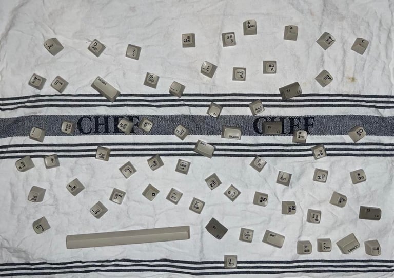
All the 66 keys are removed from the keyboard by using the keycap puller. This reveals all the dust behind the keys, but the plastic bracket holding all the plungers looks to be in good condition.
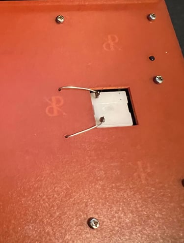
SHIFT-LOCK key is soldered to the keyboard PCB by two wires. These two are desoldered, and the SHIFT-LOCK key is removed by firmly pushing it from the backside to the frontside of the plastic chassis. The SHIFT-LOCK key will "pop" out.
All the keycaps are cleaned with luke warm water and mild soap. They look very nice after cleaning.
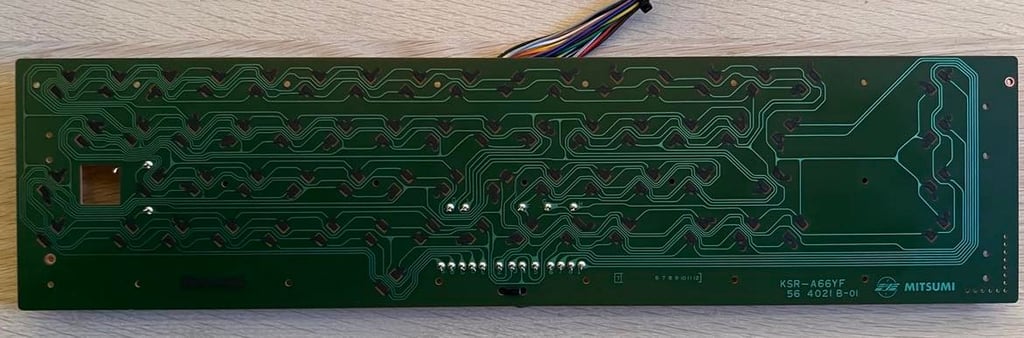
The keyboard PCB is from Mitsumi (KSR-A66YF) and looks very good already, but I clean this gently with some isopropanol. Note that is wise to be careful when cleaning the keyboard PCB since the carbon (?) pads can be damaged if you clean too hard.

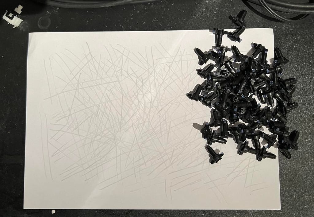
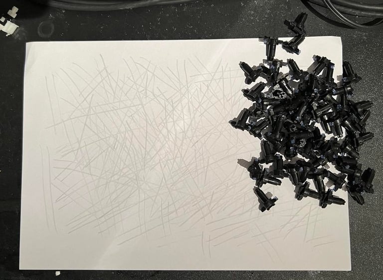
To refurbish the key plungers I use a little trick. All the plungers are carefully dragged over a blank sheet of paper. This will remove most of the grease on the plungers. I find this method more gentle than cleaning the rubber feet (carbon?) with isopropanol. This should make all the keys work as they should.
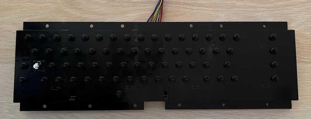
Below is a picture of the keyboard chassis with all the plungers (and SHIFT-LOCK key) back in.

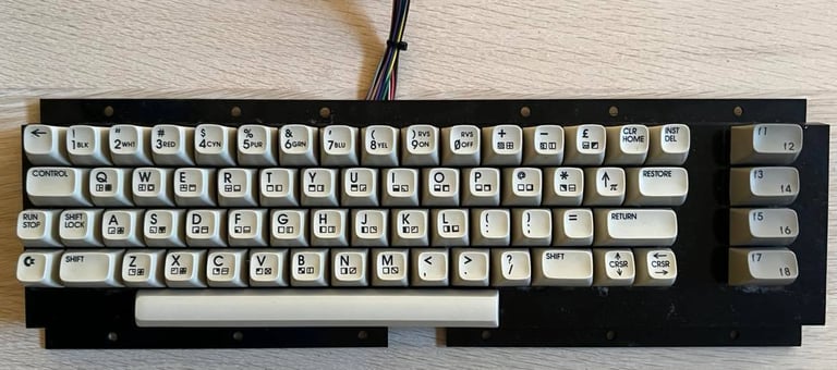
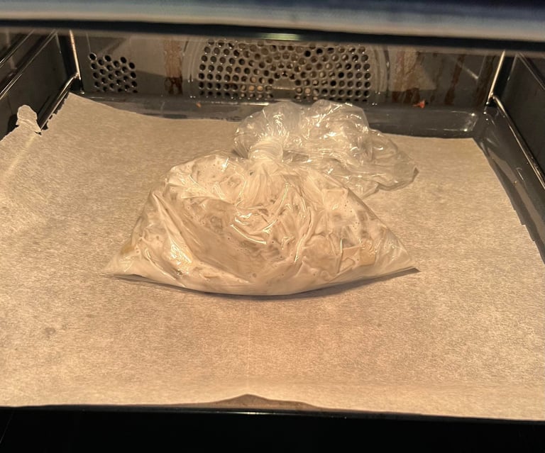
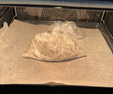
The keys are retrobrighted using 12 % hydroperoxide cream in a plastic bag together with the keycaps. And the bag is placed in the oven for 2,5 hours in 50 degrees celcius (while frequently shaking the content gently).
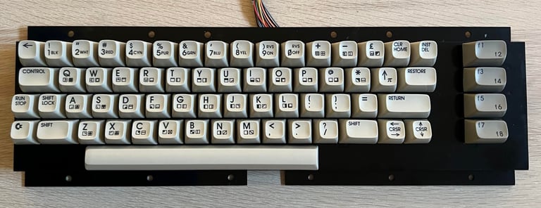
All the keys are cleaned again with mild soap water. And after drying overnight the keys are put back in the plastic keyboard chassis. Looks very good!
Mainboard
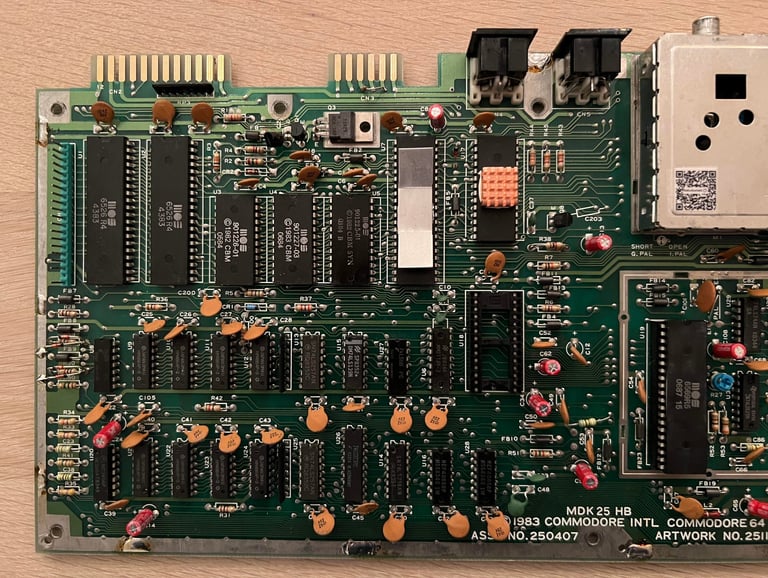
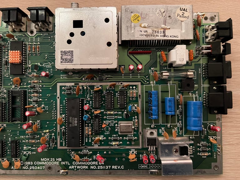
This is an assy 250407 (artwork 251137 REV C) mainboard. A very standard mainboard, but I find it very unlikely that this mainboard was mounted at assembly time. Reason for that is that the 64C was equipped with a "short mainboard" (with the exception C64C with special keys that has the assy 250466 longboard). Anyway, the C6C casing has screw holes for both the long- and short mainboard. My guess is that either the previous mainboard was defect and replaced with a "new" one, or that previous user would like to have the 6581 SID only found in long mainboard (which is my favourite I must admit).
But... as we will see later the VIC-II is quite "new" from 1987(!). So, who knows? Most likely was this long mainboard also repaired by replacing the VIC-II chip. I´ll leave it to the next owner to speculate further how this longboard ended up in this machine.
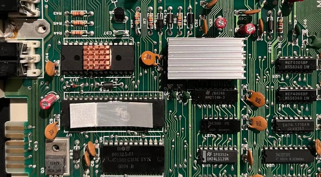
I don´t know yet if this mainboard works or not, but that will be checked soon. Below are pictures of the mainboard before refurbishment.

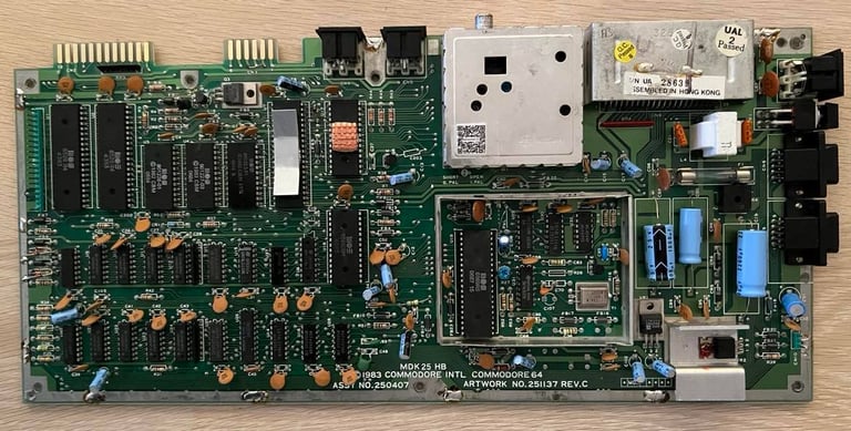

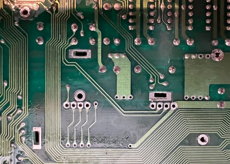
Visual inspection
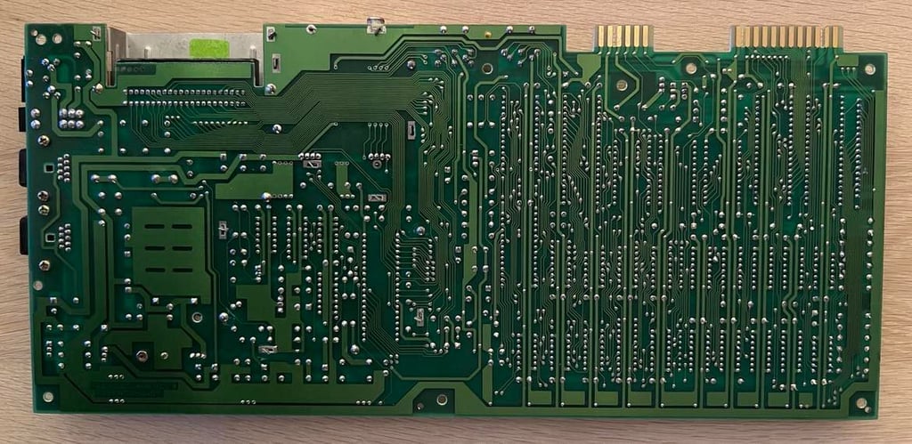
The mainboard looks good - no signs of corrosion or damage. Also, it is quite clean already (nice!). Only the SID- and VIC-II are socketed which is from production time so there are no signs of repair / reworking either. The backside of the PCB also looks very good - no signs of rework.
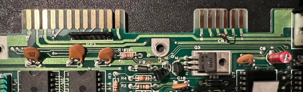
There are heatsinks mounted on the 6510 CPU and the PLA. So someone has obviously been here, but only adding these two. The heatsinks looks a bit odd I think and they are not of the same kind. I would prefer to have the same kind of heatsinks for all the critical MOS chips, but the heatsinks are stuck to the chips with termal glue. So, since these heatsinks do the work I will leave them as they are.
The 7805 voltage regulator has some sign of melting, but this is "normal" (in the sense that I have seen this before on other mainboards). This regulator get very hot and that is why it is mounted on a heatsink. Both the 7805 and 7812 voltage regulator will be replaced anyway.
Electrolytic capacitors have no sign of leakage. I rarely see any leakage, but I will replace these anyhow later as preventive maintenance. My guess is that this mainboard was produced some time around Q1 1984, and that the VIC-II was changed some time in the late 1980´s or early 1990´s.
Below is a list of all the main chips on this mainboard.
Initial testing
It is good practice to check for short circuit before power on the first time. I check for short circuit four places (check this page for details on the position of these):
User port: 5 VDC
User port: 9 VAC
7805 voltage regulator: Pin # 3 (Out) and ground
7812 voltage regulator: Pin #3 (Out) and ground
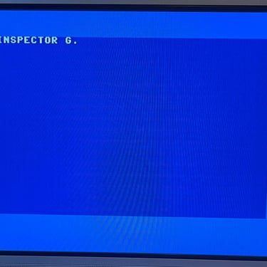
The result is that there are no short circuit so I will go ahead an power on - but first I remove the SID chip. This is not required to be installed in order for the Commodore 64 to boot up.
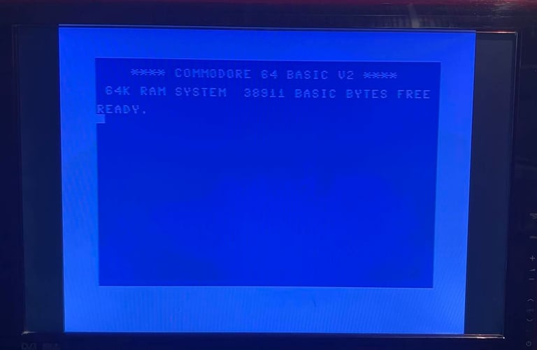
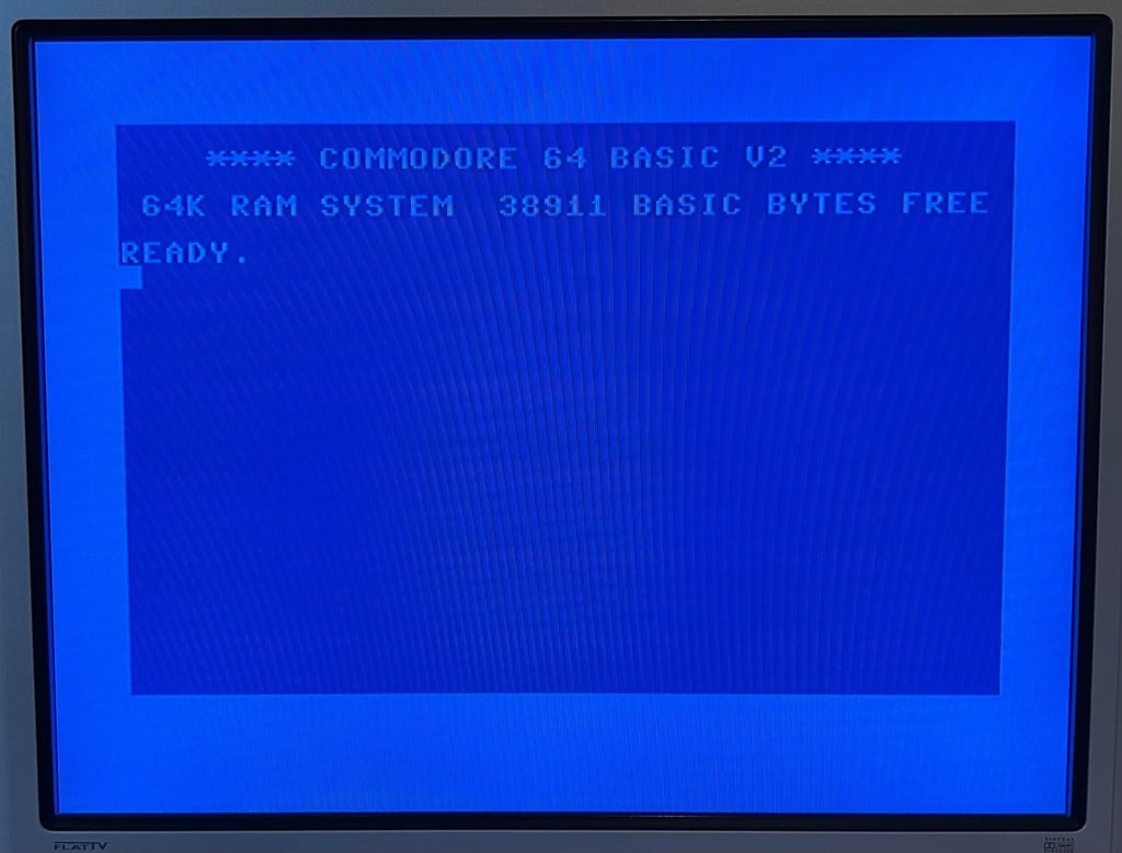
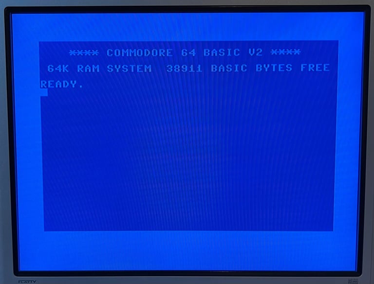
Result: Normal blue bootup screen. Perfect!
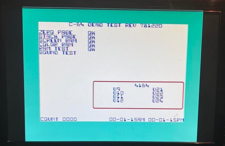
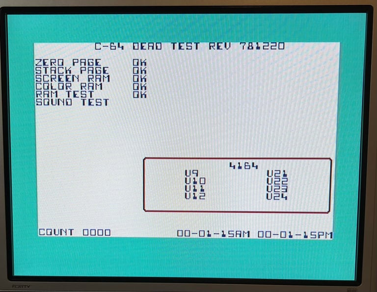
I do a quick check with the Dead Test Cartridge to check if the basic chips such as CIA, RAM etc. also works. And they do! Note; this is NOT a complete test of the Commodore 64.
Next I measure relevant voltages on the mainboard. I recommend to read the HOWTO article on which, and how, to measure voltages on the C64. They all look ok and within range, but I notice that the Vvid and Vc differ by 0.4 V. This is not any problem, but it just a bit strange I think since these two voltages are generated by the same 7805 voltage regulator. Speaking of the 7805 regulator: this get VERY hot while the power is on! Holy moly! No wonder it has melted! So thankfully this will be replaced with a completely new one!
Speaking of the 7805 regulator: this get VERY hot while the power is on! Holy moly! No wonder it has melted! So thankfully this will be replaced with a completely new one!
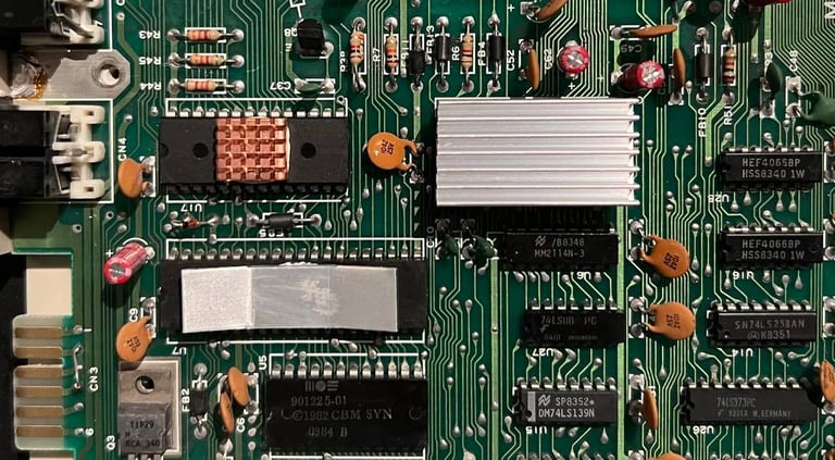
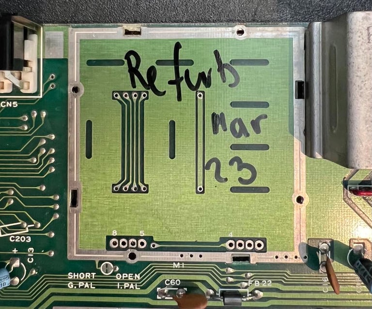
Removing the RF-shield
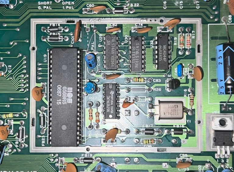
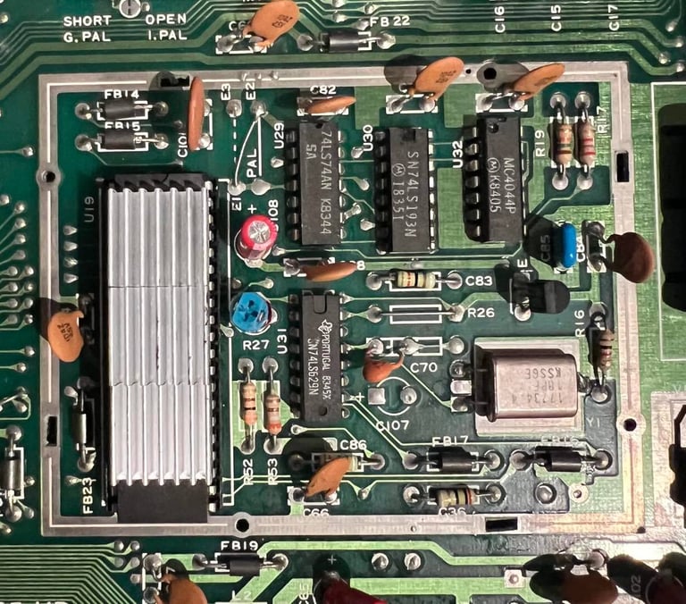
When the mainboard was produced the VIC-II, and its surround clock circuitry, were placed in a metal RF-shield. Back in the 80s signal interference was a significant problem for audio and video signals, but in our modern world this is not the case anymore. The RF-shield is preventing interference, but at the same time it locks heat into the case. And the VIC-II can get VERY hot (60-70 degrees) so trapping this heat is not welcome. So, I will desolder the whole RF-shield so that cooling air can travel free all over the mainboard. Later I will also add heatsink to the VIC-II.
Step #1: Align the four tabs to they are free to exit the small notch (blue squares).
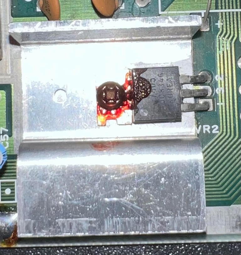
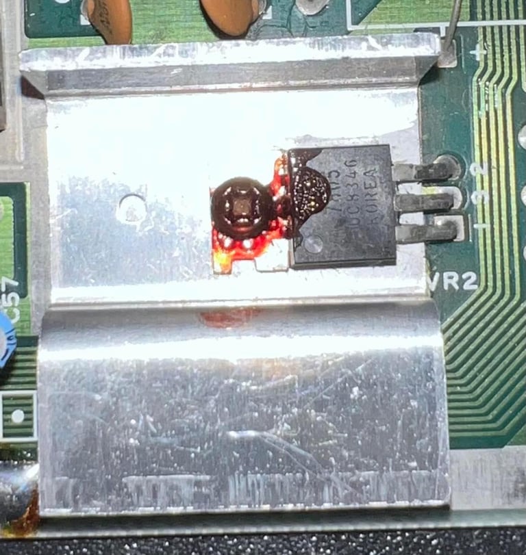
Step #2: Use both soldering iron and desoldering gun (450 degrees celcius) to remove the solder on the four large ground pins (yellow squares).
Step #3: Use a small flat screwdriver between the case edges and the mainboard while applying hot air on the large ground pins.
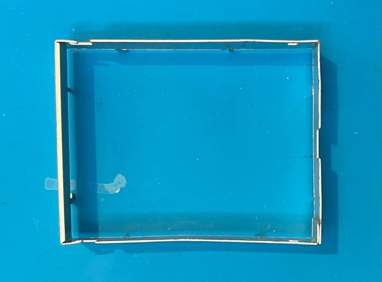
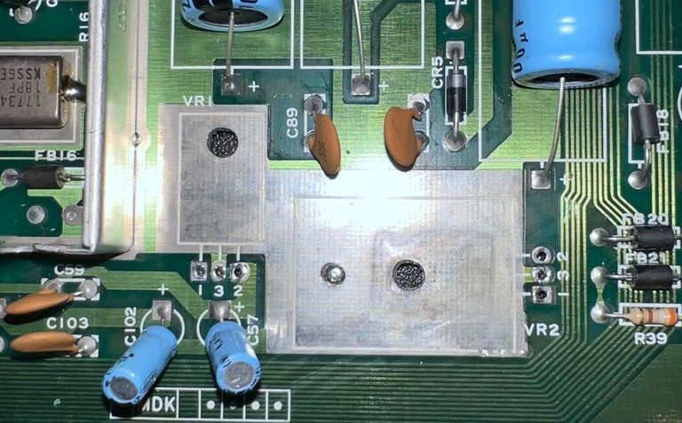
In contrast to removing e.g. the RF-modulator you "can´t" break anything when removing the RF-shield. But, I still think it is wise to be careful so that the mainboard is not damaged in any way. Below are pictures of the removed RF-shield and the VIC-II area free of any heat walls.
Replacing the voltage regulators
There are two voltage regulators on the Commodore 64 mainboard (the longboard versions): a 7805 regulator sourcing the +5 VDC and a 7812 regulator sourcing the +12 VDC. Both of these voltage sources are used for powering the SID- and VIC-II chip. For an elaborate rant about C64 voltages see the HOWTO article about the subject.
As previously mentioned the 7805 voltage regulator was burning hot (and also shows signs of melting). But both the 7805 and the 7812 voltage regulator is replaced with new ones. Note: it is only the 7805 regulator which is attached to a heatsink. This is from production. The 7812 is "floating free" from the mainboard which is normal.
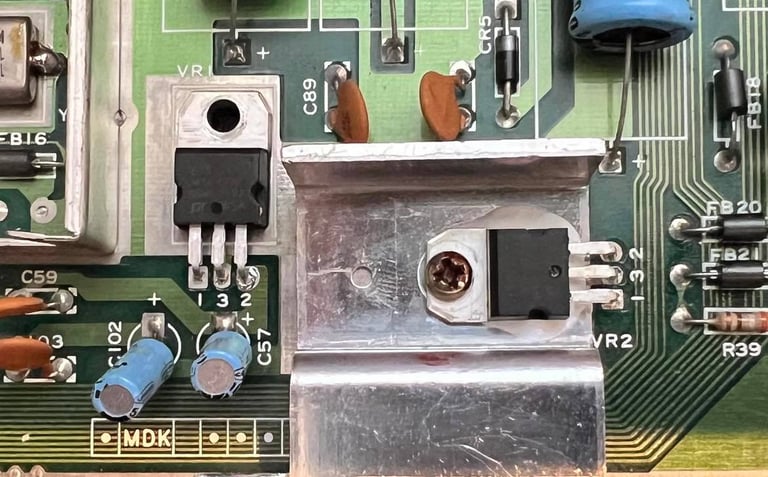
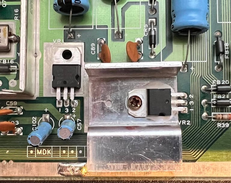
Pictures below shows the removed voltage regulators and the new ones soldered in. Note: the white "goo" beneath the 7805 is just some heat transfer silicone.
Replacing the electrolytic capacitors
Although not strictly required on this mainboard I think it is good practice to replace the electrolytic capacitors as part of the refurbishment. After 30+ years electrolytic capacitors are likely to change their ESR value ("resistance") due to old age.
As seen from the capacitor list there are 17 electrolytic capacitors on this type of mainboard (assy 250427 / artwork 251137 REV). Only quality capacitors from Panasonic Vishay and Wurth Electronics are used as replacements.


Cleaning the connectors
Perhaps one of the easiest tasks, but can make a big difference, is to clean the power input. I spray with contact cleaner into the connector and insert/remove the power plug several times (10-20 times). This will remove much of the oxidation and could quite often increase the voltage to the mainboard - which could be very important for the Commodore 64 to operate flawlessly.
Also the serial-, A/V- and cartridge connector is cleaned the same way. I have not seen that this have the same effect as with the power input, but it is good to know that the connectors are cleaned as good as possible.
To clean the user port and the datasette port I first rub the copper traces with an eraser (yes, a normal rubber eraser from school). Afterwards the connectors are cleaned with isopropanol and Q-tip.

Adding heatsinks
There are already installed heatsinks on the CPU and the PLA which is good. In addition I add heatsinks to the SID and the VIC-II chip. As a matter of fact it is these two last chips which are the most valuable - and also those who generate the most heat.

RF modulator
The general purpose of the RF-modulator in the Commodore 64 is to combine the analog signals from the VIC-II and SID chip into a working TV-signal. A TV signal that has both audio and video. There are no fancy digital ICs inside the RF-modulator. Instead, there are analog components such as transistors, resistors, capacitors and coils. Among these, there are one kind which are prone to alter their values; the electrolytic capacitors. In the schematics below you can see how the RF-modulator combines the signals from the VIC-II and the SID and expose these as COMP, LUM, COLOR and AUDIO on the DIN connector.
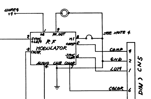

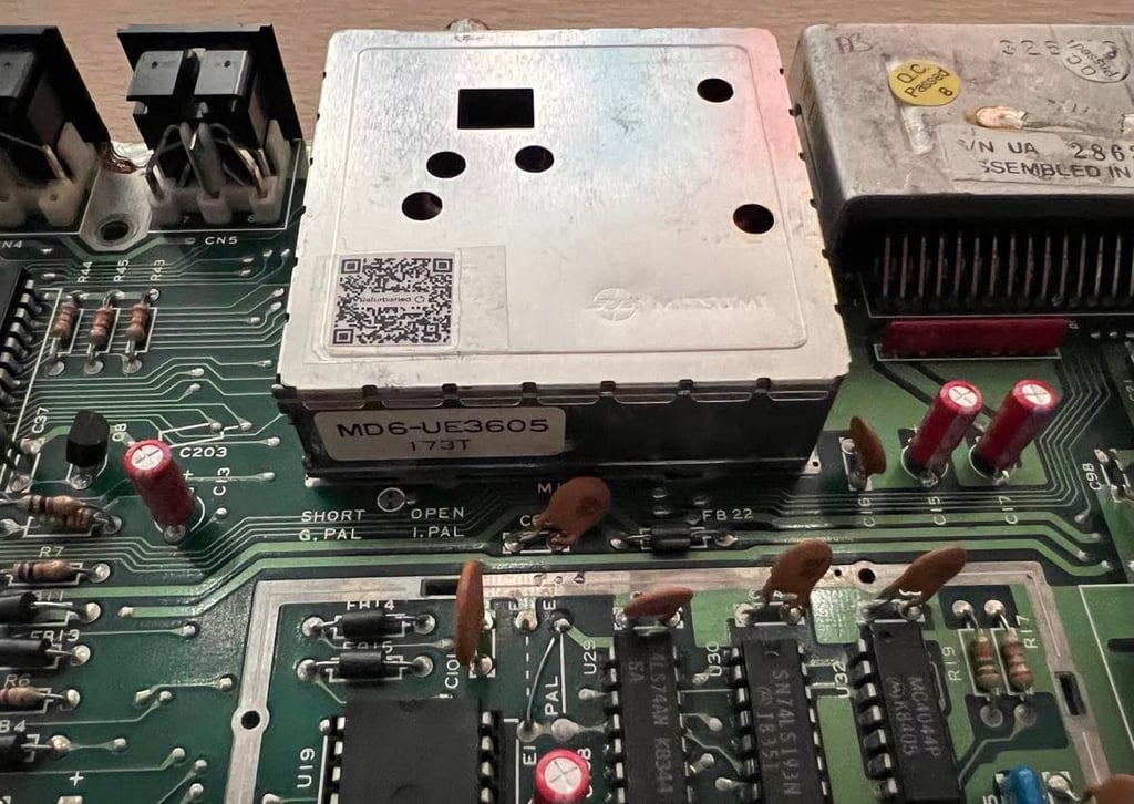
As seen from the schematics above the RF-modulator is often shown as a "black box" with four inputs and four outputs. This is a Mitsumi MD6-UE3605 [173] modulator.
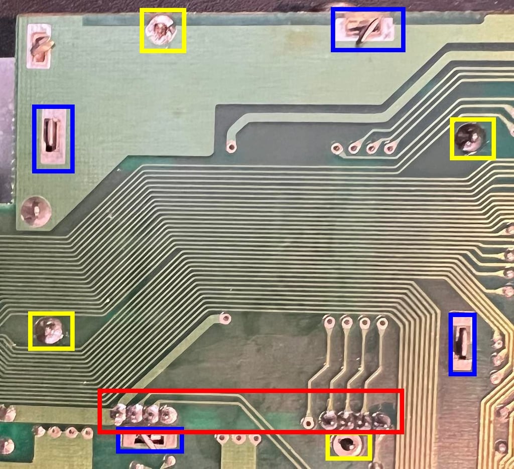
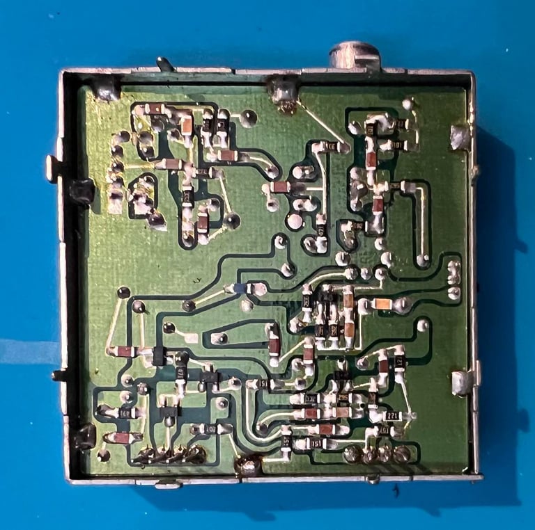
To replace the electrolytic capacitors in the RF-modulator the whole casing needs to be desoldered. Even if I´ve desoldered quite a few of these I still say that it is not trivial to do it. You need to be very careful so no traces / pads / pins are destroyed during the operation.
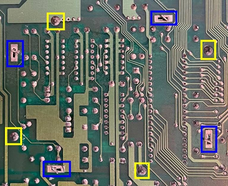
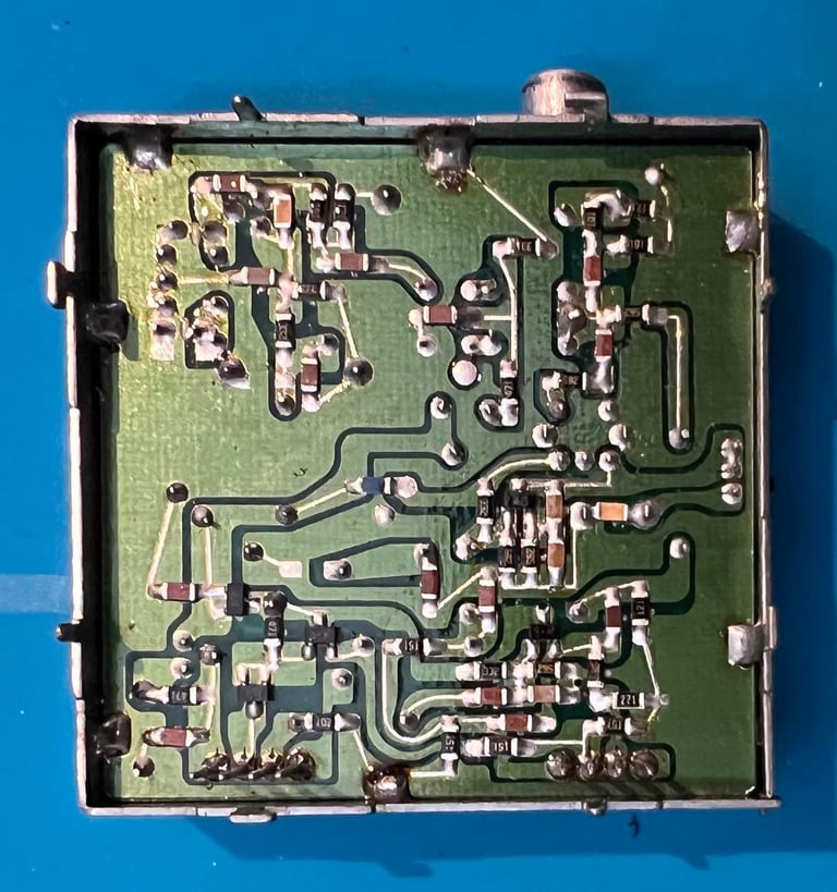
Step #1: Straighten the four tabs so they are aligned with the notch (blue squares).
Step #2: Desolder the four large ground pins holding the casing to the mainboard (yellow squares). The way I do this is to heat both soldering- and desoldering iron to 450 degrees celcius. Then I apply both the soldering iron and the desoldering gun to the pin to make sure I get a good floating soldering. Then the solder is sucked away.
Step #3: Lowering the desoldering gun to about 370-390 degrees and remove the solder from the eight pins (red square). Often, it can be a good idea to use some fresh solder on these pins first.

Next I use a small flat screwdriver between the RF-modulator casing and mainboard. And carefully I start to lift the casing off while I apply hot air (400 degrees) in the areas of the large pins. It is wise to be in "zen" mode when doing this. Take your time and don´t rush it. After some careful working it will come off. And as seen from the picture below no trace or pad were lifted. Success!

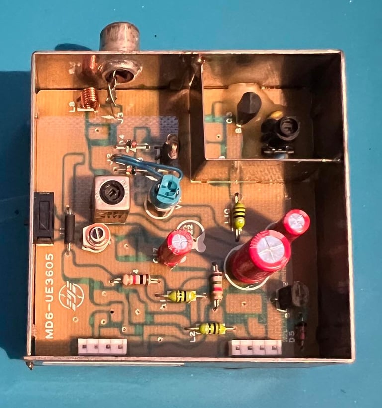
Below is a picture of the RF-modulator before the new electrolytic capacitors are installed. I notice that this RF-modulator has a 10 V rating on the 330 uF cap. Previous versions of the same modulator has a 6.3 V rating. But I will replace it with a 10 V rating to so that it is identical. BTW: if you need to replace capacitors in the RF-modulator you can order complete packages from Retroleum in the UK.
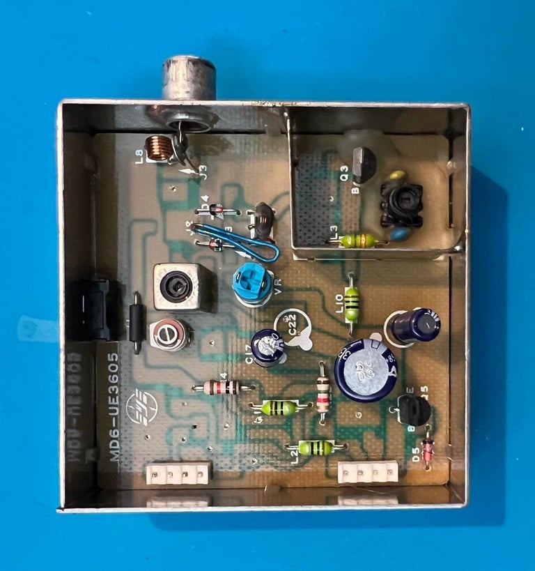
New quality electrolytic capacitors are replaced: 1 x 10 uF [16V], 1 x 100 uF [10V] and 1 x 330 uF [10V]. See capacitor list.
Finally the RF-modulator is soldered back on to the mainboard. All relevant voltages are now measured again to make sure they are within range - and the voltage table is updated.

Testing
The testing is to verify that the Commodore 64C works as expected. I do the testing in two main stages:
Basic functionality testing
Extended - real use testing
Basic functionality testing
Normal boot up screen: I check that the Commodore 64 starts with normal blue screen and 38911 BASIC BYTES FREE. Result: Passed.
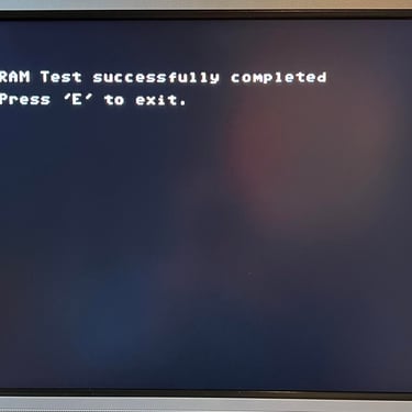
Dead test cartridge: This cartridge may be simplistic, but it is very powerful. It test all the basic functionality found in the CPU, VIC-II, SID, PLA, RAM (including Color) and both CIA chips. I stress that this is only the basic functionalities of these chips, but they need to operational for the C64C to work at all. Result: Passed.
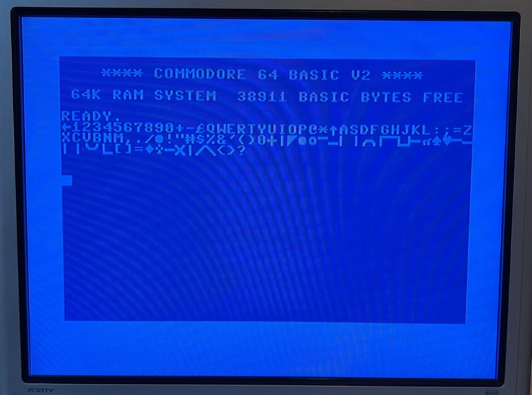
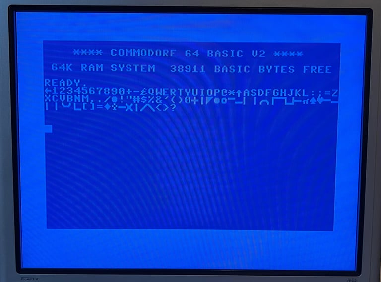
Keyboard: All keys are pressed one-by-one to make sure they all work, and that the pressure required for the key to react is ok. Also, the keys are pressed while the SHIFT-LOCK is enabled. This shows that both the SHIFT-LOCK key work, and that all PETSCII characters are present in the 901225-01 Character ROM. Result: Passed.
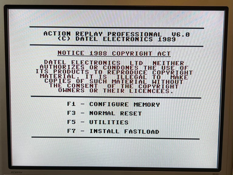
Cartridge port: Short basic test by verifying that the Action Replay MK VI is operational. Result: Passed.

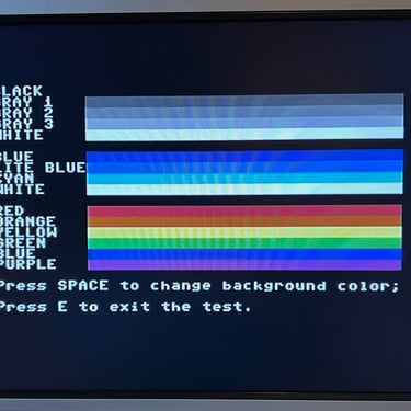
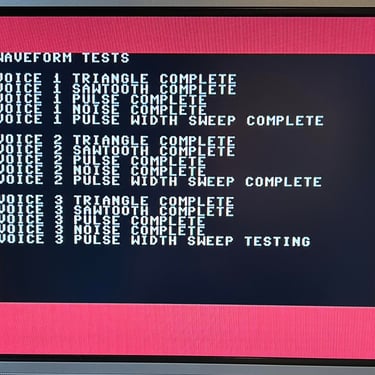
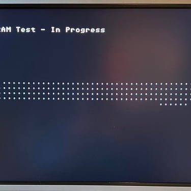
VIC-II, SID and RAM: Using 64 Doctor and Commodore 64 SID tester software to check the basic functionalities of these chips. Again, I stress that these tests are only basic (they do not test sprites, different video modes, advanced SID filtering etc) . Result: Passed.
Extended / real use testing
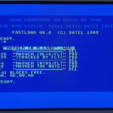
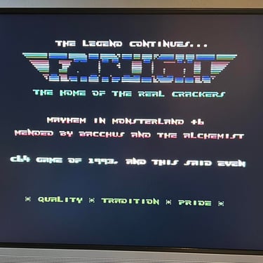
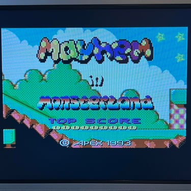
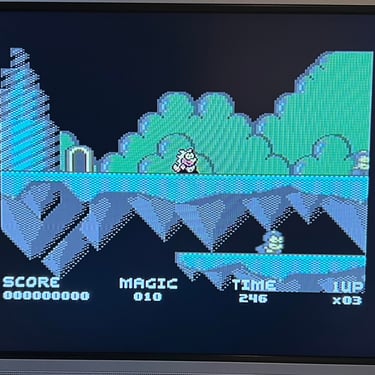
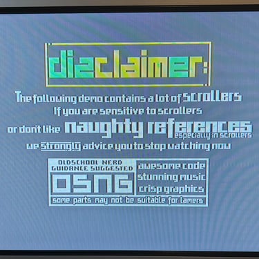
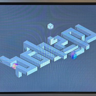
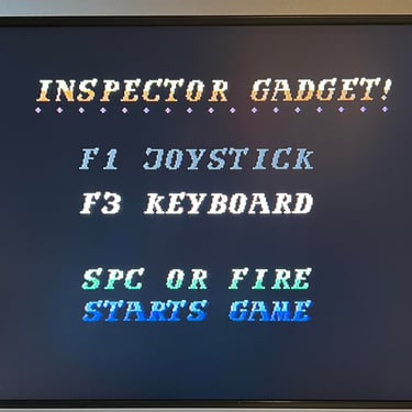
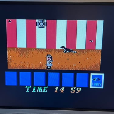
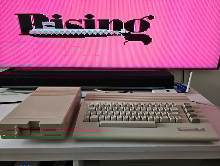
To really test that everything works as it should I use an Ultimate 1541 II+ cartridge. This is a "swiss army" tool where I can test features such as disk access, tape loading, cartridge and more. I use the machine playing games, watching demos, loading from tape and disk. I can not find any issues with either video, audio, storage access or control ports. Result: Passed.
Below is a little gallery from my testing.

"A picture worth a thousand words"
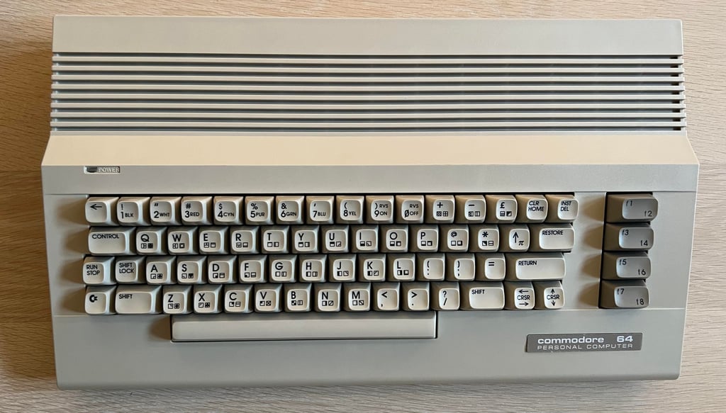
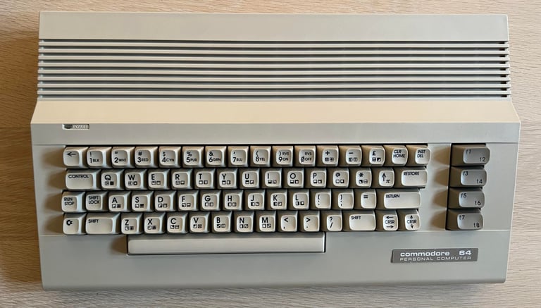
Below is a collection of the final result from the refurbishment of this C64C. Hope you like it! Click to enlarge!
Final result


"Are you keeping up with the Commodore? 'Cause the Commodore is keepin up with you!"
Below is a picture of the Commodore 64C back home at the customer!
