

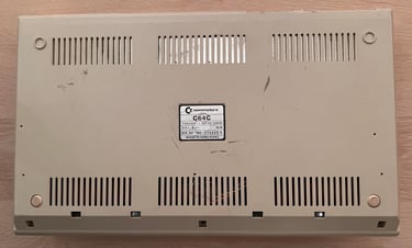
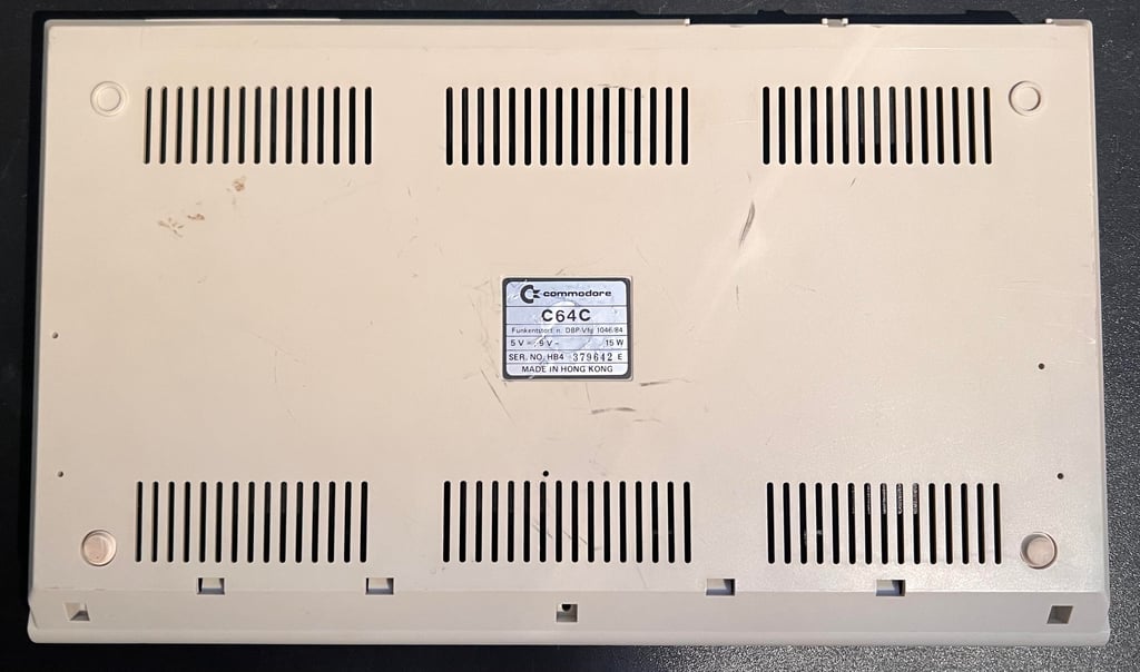
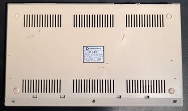
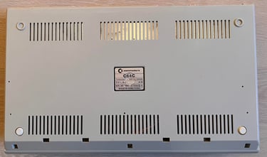
C64C [PAL]
Ser. No. 379642
Assy 250469
Artwork 252311 (REV 3)
Starting point
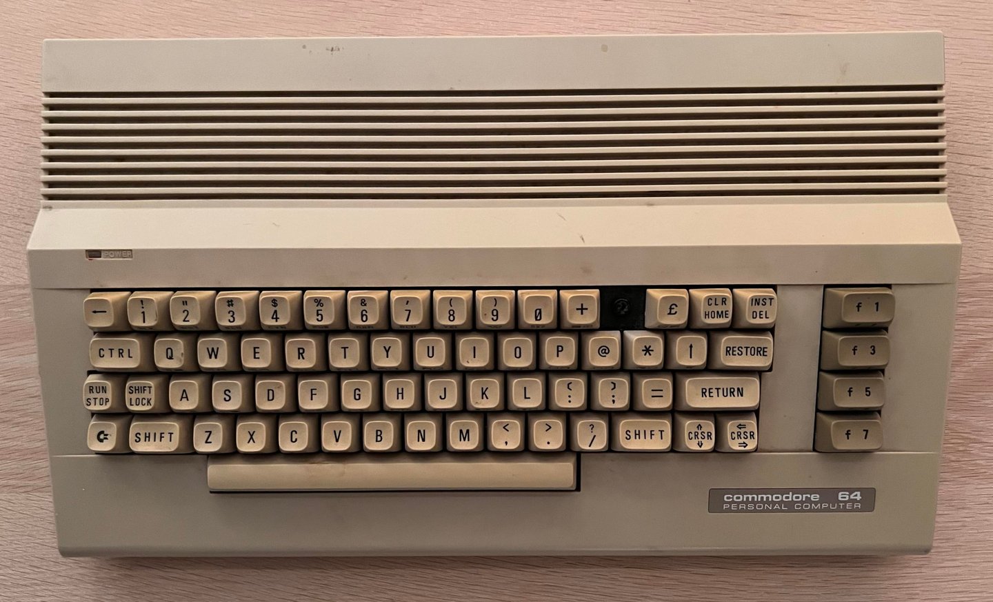
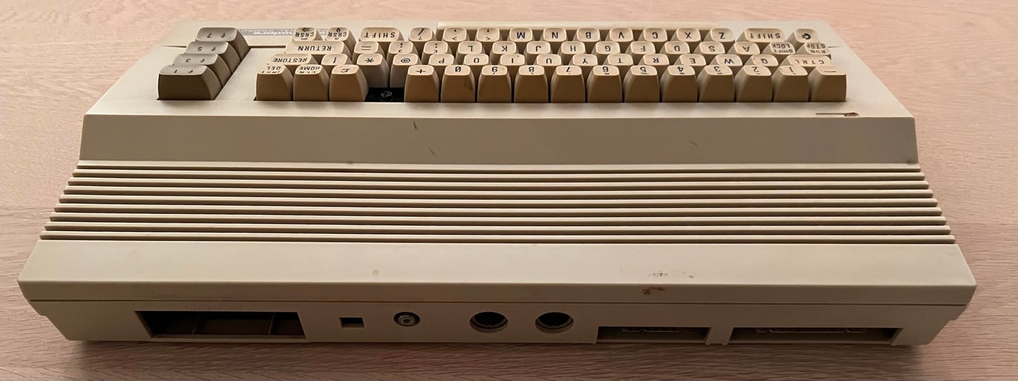
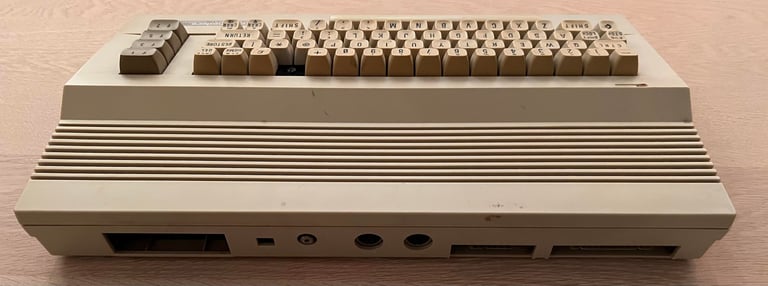
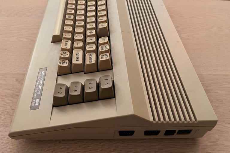
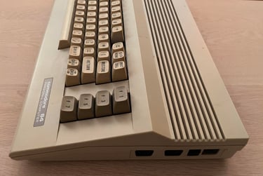
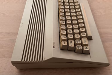
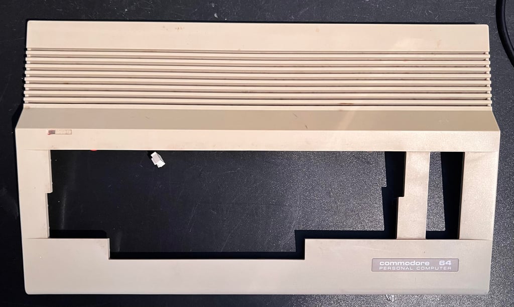
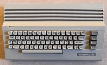
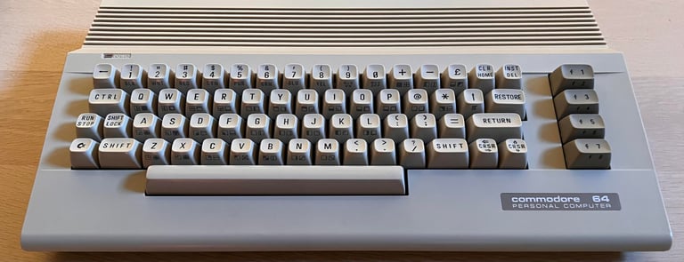
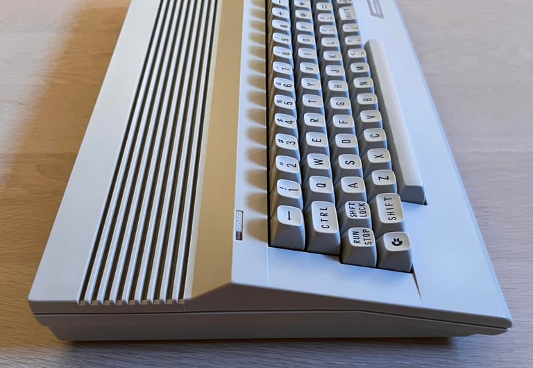
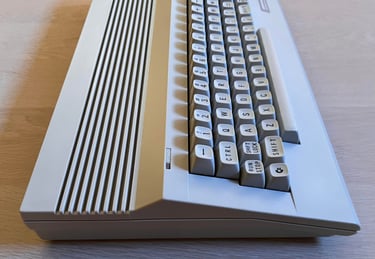
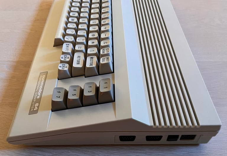
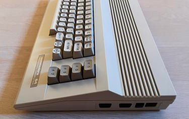
I have no idea if this machine works or not, but from the outside it doesn´t look too bad. Obviously the "-" key is missing and it is quite dirty (and yellowed), but all in all I think it appears to be in quite ok condition. One of the three screws at the bottom cover is missing, so this machine has probably been opened previously. This machine has the original print design on the keycaps. That means that each of the keycap has the letter ("A", "B", "C" etc.) on top of the key, and the symbols printed on the front of the keycap. On later revisions both the letters and symbols were printed on top - probably to save cost (or look more modern).
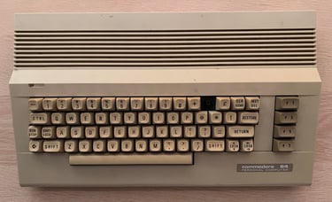
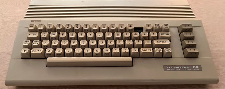
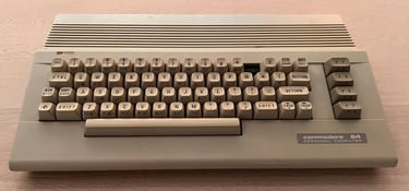
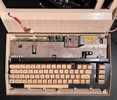
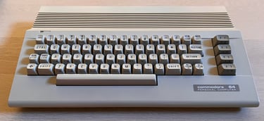
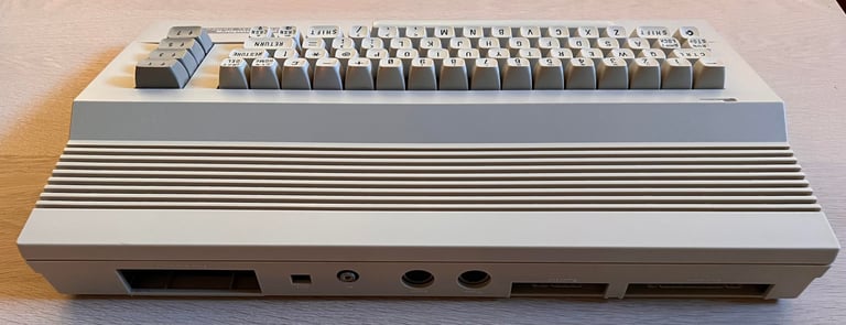
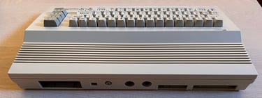
Below are some pictures of the machine before the refurbishment.


Refurbishment plan
The refurbishment plan for this C64C (order can vary and some of the tasks will be done in parallell):
- Clean and remove stains from the chassis
- Clean and restore the keyboard
- Refurbish main board (cleaning, checking, repairing, replacing capacitors etc.)
- Recap RF-modulator
- Verify operation by testing
The plan can be updated during the refurbishment process. Sometimes I discover areas that needs special attention.
Opens it up...
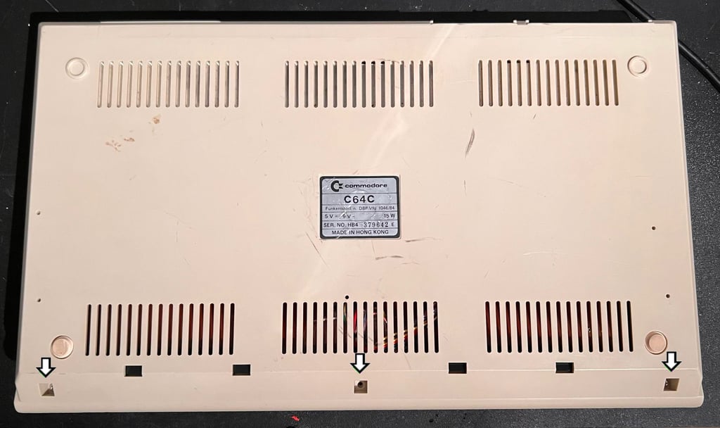
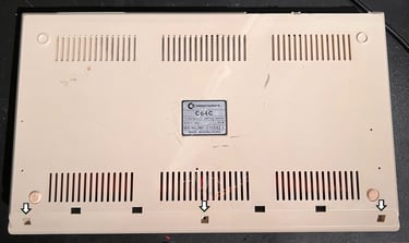
Opening the Commodore 64 C is straightforward. The top- and bottom cover are held together by three screws at the bottom (where one of the screws is already missing).
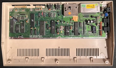
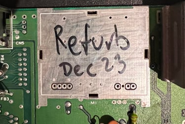
The top cover is lifted off and the LED connector is removed from the mainboard. There is quite some dust and dirt inside, and the RF-shield in metal is oxizided with some minor corrosion. But other then that I can not see any damage.
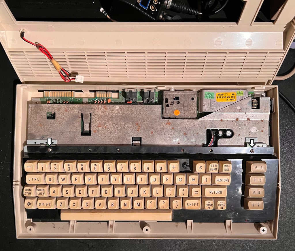
Now the two machine screws (see arrows in picture above) are removed from the keyboard. The keyboard is then slided upwards so that it is released from the bottom cover, and finally the keyboard connector is carefully pulled off the mainboard.

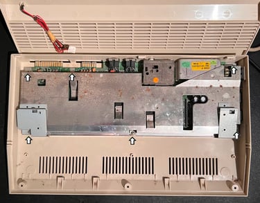
There are six screws attaching the metal shield to the mainboard PCB which are removed. This metal shield has three purposes in the Commodore 64C:
Bracket support for the keyboard
Function as heat sinks for the MOS 8580 (SID), MOS 8565 (VIC-II) and MOS 8500 (CPU) chip
Act as a shield for electromagnetic interference from / to the mainboard (RF-shielding)
The latter has no real function in modern times, but since it also functions as a bracket for the keyboard it can´t be discarded as is often the case in older Commodore 64s. With the metal shield out of the way the mainboard is finally revealed. There is quite some dust and grease inside, but other than that it looks to be in quite ok condition. The seven screws holding the mainboard to the bottom cover are removed.
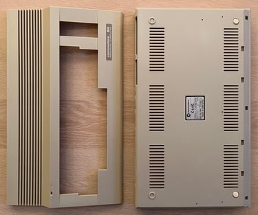
Exterior casing
Both the top- and bottom cover appear to be without any damage. But it is quite dirty and with several stains and marks. Also, it is yellowed, but it is not the worst yellowing I have seen. Below are pictures of the covers before cleaning.

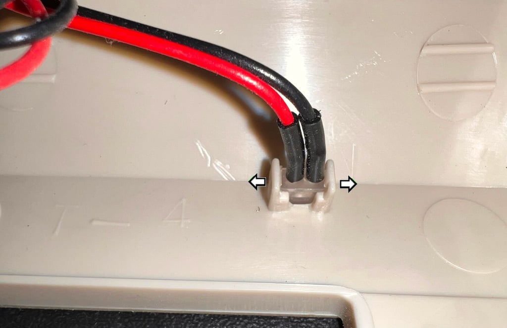
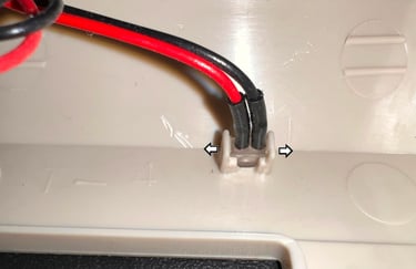
Before cleaning the LED is removed. This is not strictly required, but good practice to avoid any damage due to cleaning (and retrobrighting later). To remove the LED the two small plastic tabs are carefully pushed outwards (see arrows in picture below). Make sure to be gentle with this as the plastic can be very brittle and can easily break.
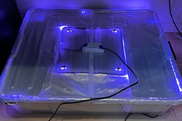
The covers are cleaned thoroughly with water and mild dishwashing soap. This removes most of the grease, but the stains are removed with plenty of isopropanol and hard work scrubbing it. After cleaning both covers are retrobrighted with 12 % hydroperoxide cream and UV for about 12 hours. During retrobrighting the covers are wrapped in plastic cling film and the cream is re-applied regularly (about every hour).

The result is very good in my opinion. Most of the yellowing is gone, and most of the marks are removed. As good as new!

Keyboard
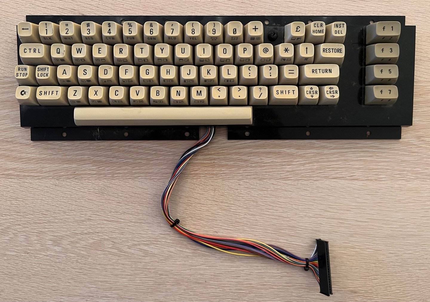
The keyboard is very dirty, the "-" key is missing (and the plunger broken) and the keycaps are severely yellowed.
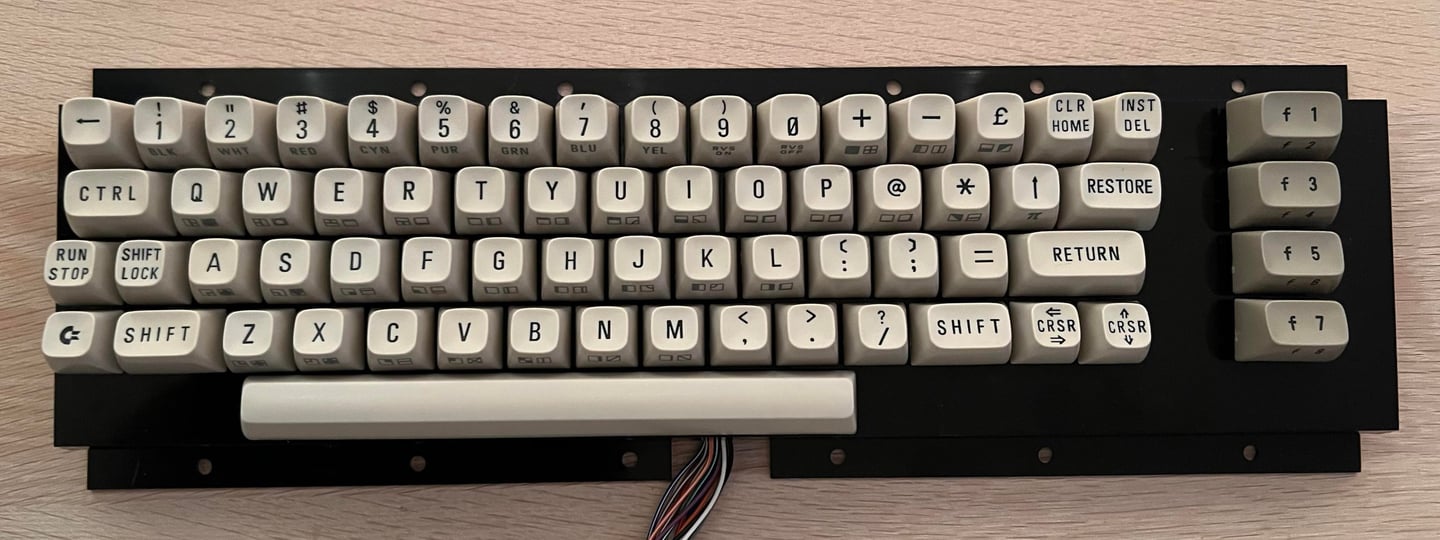
A complete, and very detailed, description of the refurbishment of the keyboard can be found in the HOWTO article "Refurbish the C64 keyboard". The reason for that is that this very keyboard was used to create the article. Nevertheless, below are some "before" and "after" pictures of the refurbishment.
BEFORE:
AFTER:
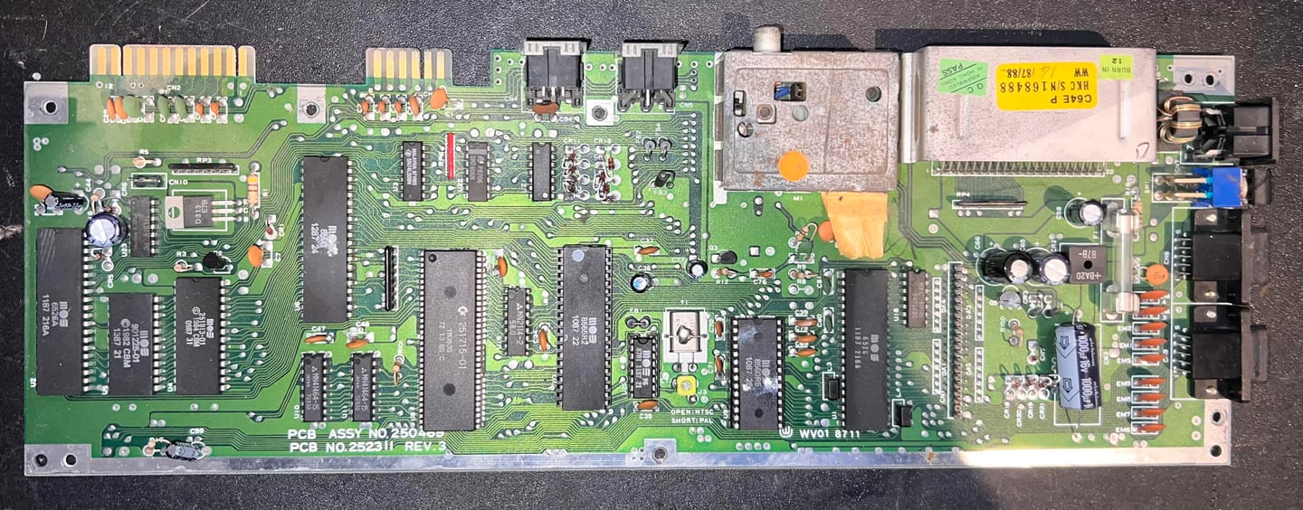
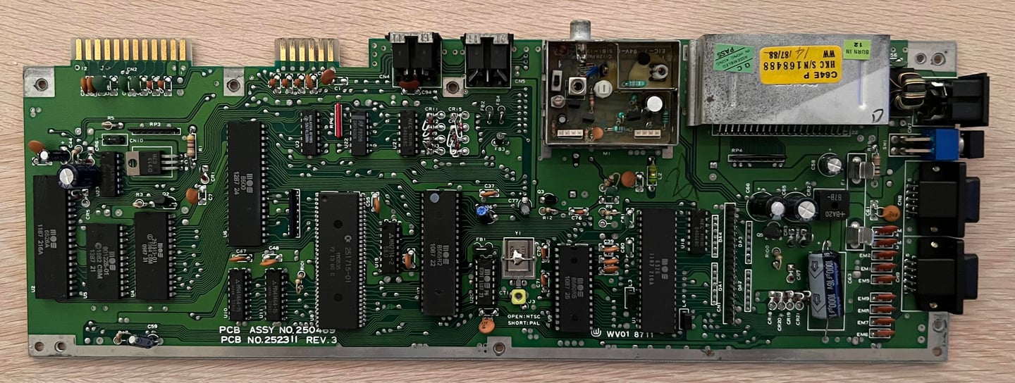
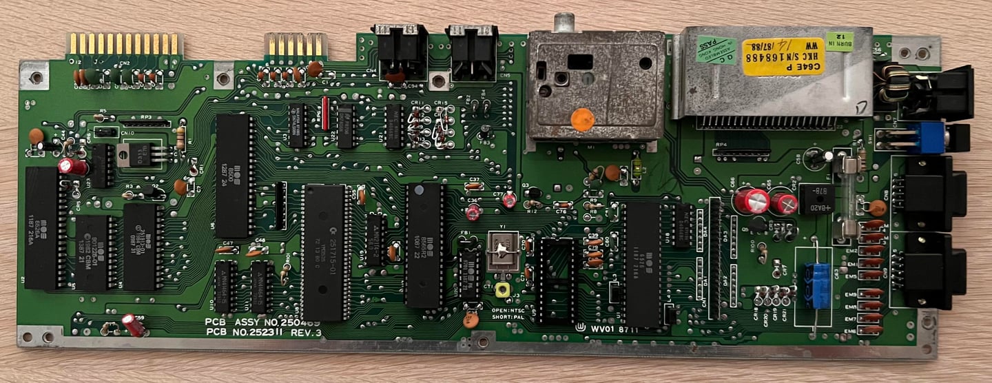
Mainboard
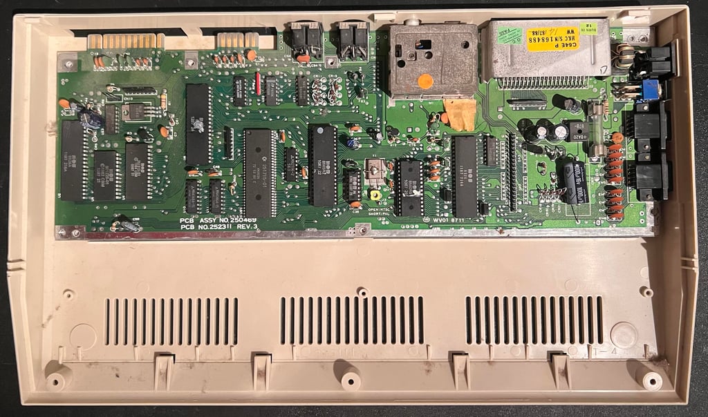
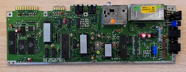
This is an Assy 250469/Artwork 252311 (Rev 3) mainboard - often classified as a "shortboard" version. Compared to "longboard" typically found on C64 breadbins (but can also be found in early revisions of C64C) it differs in some areas:
64 pin Super PLA – Compared to the old 28 pin PLA this Super PLA contains in addition to PLA functionality a lot of the other glue logic.
No 12 V rail used to supply the VIC-II and SID – Compared to the old breadbin which has dedicated 7805 and 7812 voltage regulators to supply additional voltage sources.
MOS 8500 CPU – Compared to the Commodore 64 breadbin which normally use the MOS 6510 CPU (note that these chips are interchangeable so they could be used in both).
MOS 8580 SID -Compared to the breadbin which use the MOS 6581 SID. Note that these are not interchangeable since they use different voltage supplies.
MOS 8565 VIC-II – Compared to the breadbin which use the MOS 6569 VIC-II. Note that these are not interchangeable since they use different voltage supplies.
Visual inspection
The picture in the "Opens it up..." does not really show how dirty this mainboard is. There is dirt and grease all over. The thermal paste is old and sticky. But other than that I can not see obvious damage or any sign of major corrosion on the mainboard. And I can not see any sign of rework or repair.
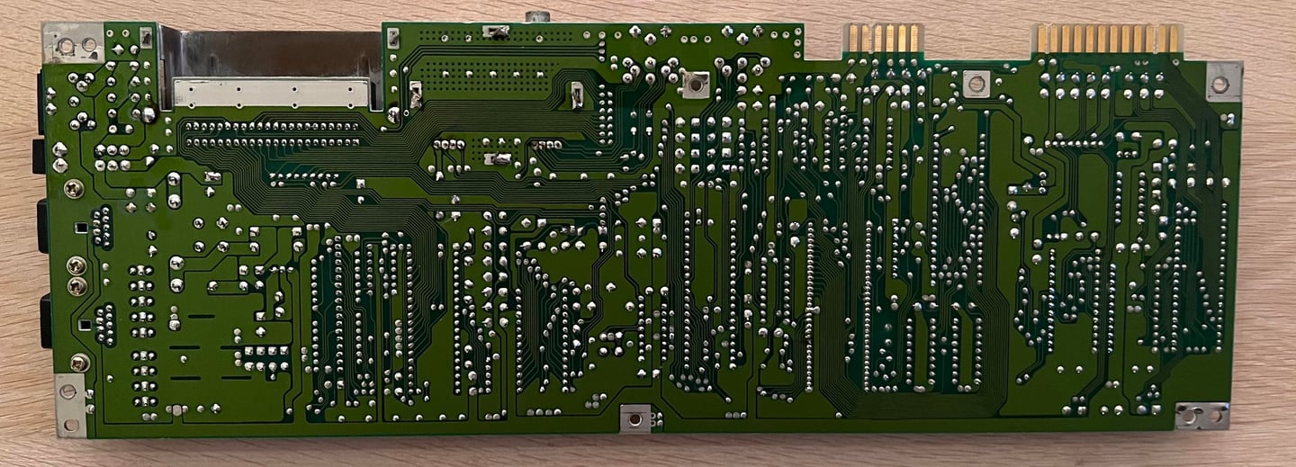
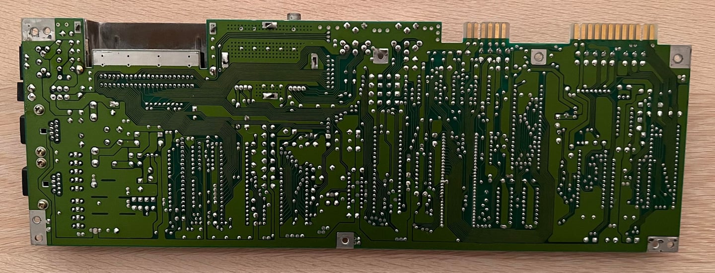
The mainboard is washed thoroughly with water, mild dishwasher soap and a soft paint brush. When washing the mainboard it is good practice to remove the glass fuse, remove (desolder) the top metal lid on the RF-modulator and socketed ICs. It is not that the ICs can´t withstand water, but it is often the case that the small pockets in the sockets (it rhymes!) tend to dry very slowly. The glass fuse is not water proof though.
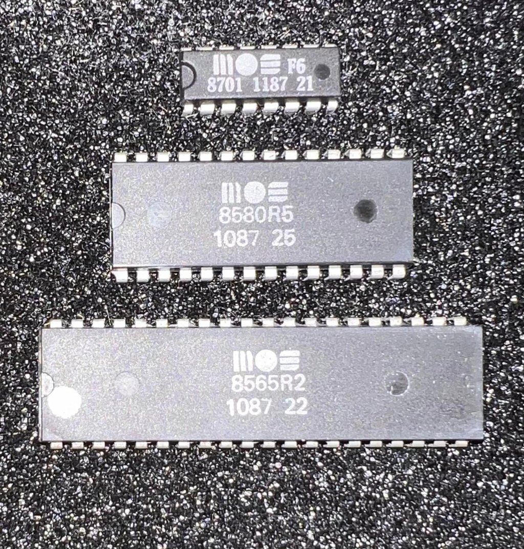
When removing the socketed ICs it is a good thing to stick them onto anti static pads - this will protect them (and you don´t loose them!). Also, the legs of the ICs are cleaned with isopropanol on an old tooth brush. Below are pictures from the ICs and the top and bottom side of the mainboard after cleaning.
Below is a table of all the main chips on the mainboard. The table will be updated if any ICs needs to be replaced:
Replacing the electrolytic capacitors - mainboard
The electrolytic capacitors are 35+ years old and the problem with old capacitors is that the dielectric material can dry out. On the Commodore 64 this is normally not a big problem, but if the capacitors dry out the capacitance and ESR will change. This can lead to spurious faults on the Commodore 64. Therefore it is good practice to replace these with new modern replacement capacitors. I order quality capacitors from Mouser.
In the pictures below the mainboard is shown with the new capacitors in place.
Replacing the electrolytic capacitors - RF modulator
According to the reference bank there should be two electrolytic capacitors in the RF-modulator with part number 251916-02. In my opinion it is more important to replace the electrolytic capacitors in the RF-modulator than on the mainboard. Why? Well, since the capacitors are a vital part of the analog filtering a "bad" capacitor can cause disturbance in the audio- or video signal.
But, alas, desoldering the RF-modulator from the mainboard is not trivial. By all means, it is not impossible, but you need to know what you are doing - to avoid damaging the RF-modulator PCB and/or the mainboard PCB. I have made a HOWTO article describing how I do this so please have a look.
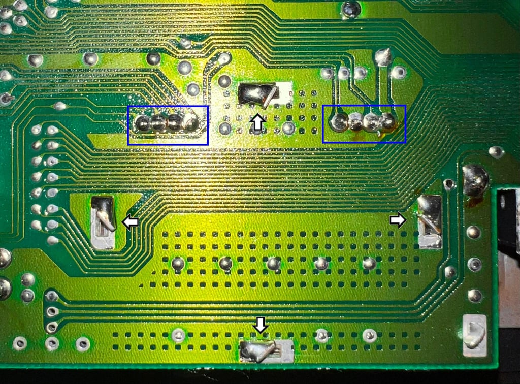
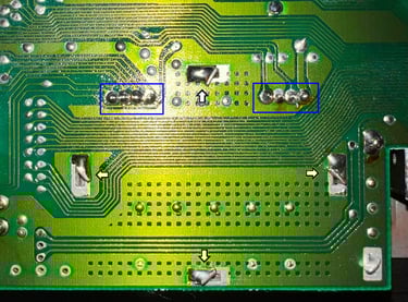
The four large metal tabs are desoldered, freed from any residual solder and twisted to a straight angle fitting the hole (see arrows in picture below). Then the eight pins connecting the RF-modulator to the mainboard are desoldered (see blue squares in picture below). Note: you need to have a quite hight temperature on the metal tabs (about 400 degrees Celcius) to get enough heat to desolder, but make sure you reduce the temperature as much as possible when desoldering the eight pins from the RF-modulator so avoid damage.
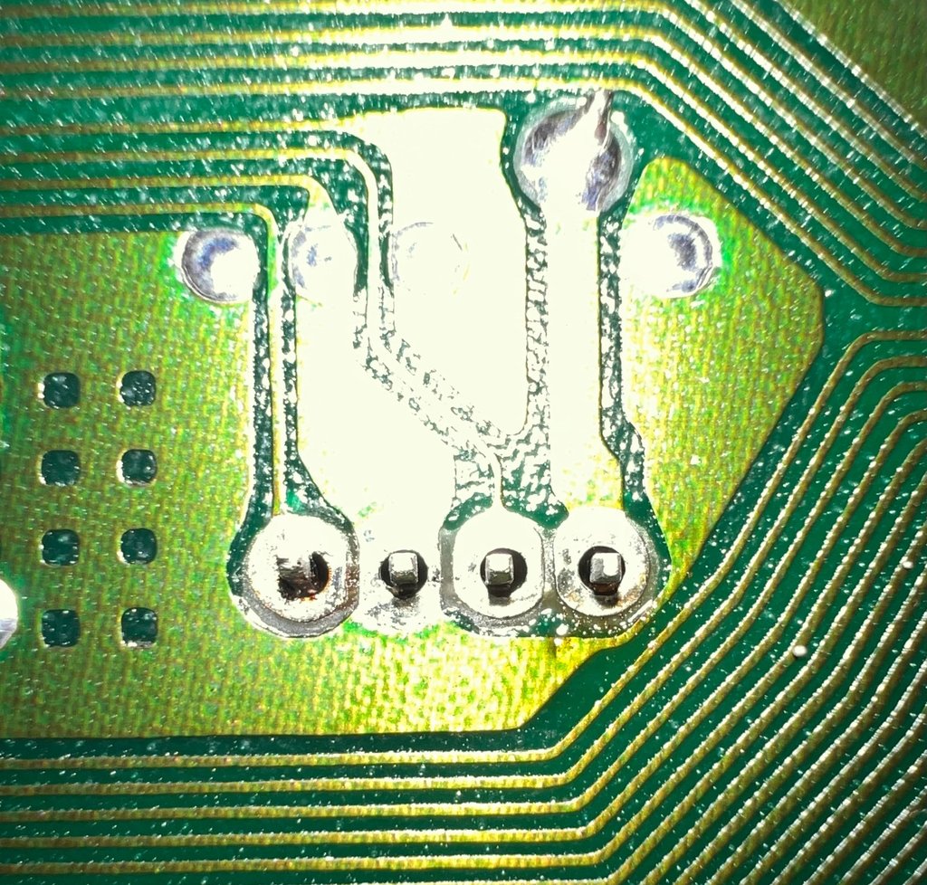
As for the metal tabs, it is important to clear the holes from solder also from the eight connector pins. This can be a bit tricky, and often you need to re-apply solder and desolder a few times. Check with a thin small screwdriver that the pins are freed. The holes and pins should look like this - see picture below.

Even if the RF-modulator is becoming freed from the mainboard now, I still recommend using hot air on all pins and metal tabs while carefully prying the RF-modulator off the board. This will reduce the risk from damaging both the RF-modulator and the mainboard.
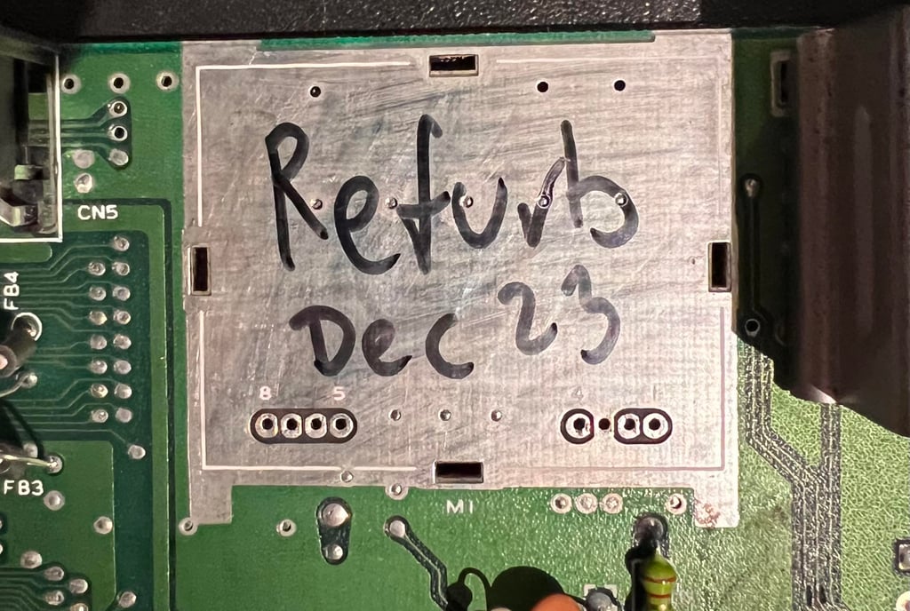
No damage was done to either RF-modulator or mainboard while desoldering this time. See picture below.
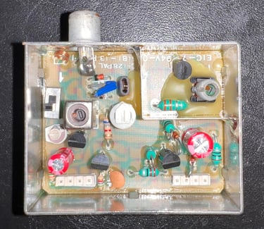
The two electrolytic capacitors are replaced: 1 x 10 uF [16V] and 1 x 220 uF [10V]. Below is a picture of the RF-modulator with the new capacitors in place.

Checking the voltages
All voltages are measured ok which is good - see table below. They will be measured again after refurbishment, but the voltage levels as they are now should at least not make any problems
Adding heat sinks to custom MOS chips
Cooling is essential if a chip is to last long. The C64C is running much cooler compared to the C64 breadbin model, but it is still good practice to add heat sinks to the most crucial (and hot) ICs; the MOS 8500 (CPU), MOS 8580 (SID) and MOS 8585 (VIC-II).
Most of the heat dissipation is through the IC pins to the mainboard, but the heat sinks will improve the dissipation of heat to the surrounding air. In effect this will cause the ICs to maintain a lower temperature when the machine is in operation – increasing the probability for the ICs to last longer.
Below is a picture of the mainboard with the heat sinks installed.

Reviving the user- and datasette port
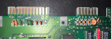
For the Commodore 64 to work flawlessly with peripherals such as datasette and modem the ports needs to be clean. After many years the connectors are oxidized and dirty. To revive the user- and datasette a rubber eraser is used to remove most of the grease and oxidation. Then some isopropanol on a Q-tip is used to rinse all the contacts. The result is shown below.

Testing
Proof is in the pudding - does it work?
Testing is done through two main stages:
Testing the basic functionality and chips
Testing by using the machine playing demos, games etc. accessed by both floppy and datasette to verify correct operation
Basic functionality and chips
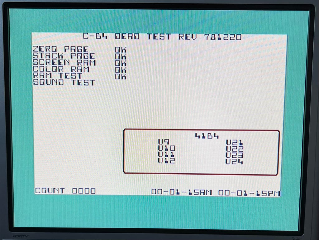
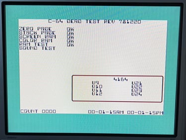
First test is done using the Dead Test Cartridge. This test doesn´t test all the functionality of the Commodore 64, but it does test the basic functionality of the major chips such as the CIA #1/2, CPU, VIC-II, PLA, RAM and SID. As the picture shows below the test is passed.
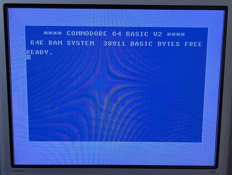
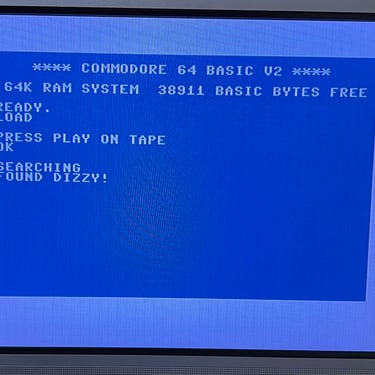
Next test is to power the Commodore 64 to the blue boot up screen and also check the keyboard to make sure all keys works as they should. The test is passed; all keys works and 38911 BASIC Bytes Free.

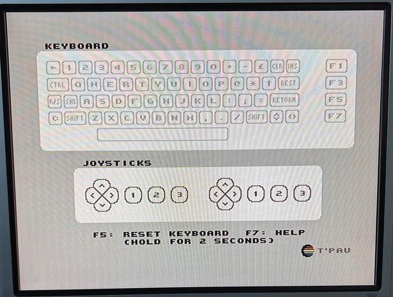
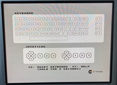
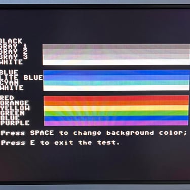
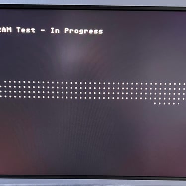
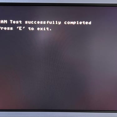
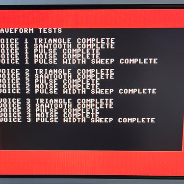
The basic functions of the VIC-II, SID and RAM is tested with 64 Doctor and Commodore 64 SID tester. Note that this is to be considered as basic functionality - more advanced (?) functionality such as sprite handling / collision detection / advanced audio will be tested later. But the basic tests pass without any detected faults (click to enlarge).
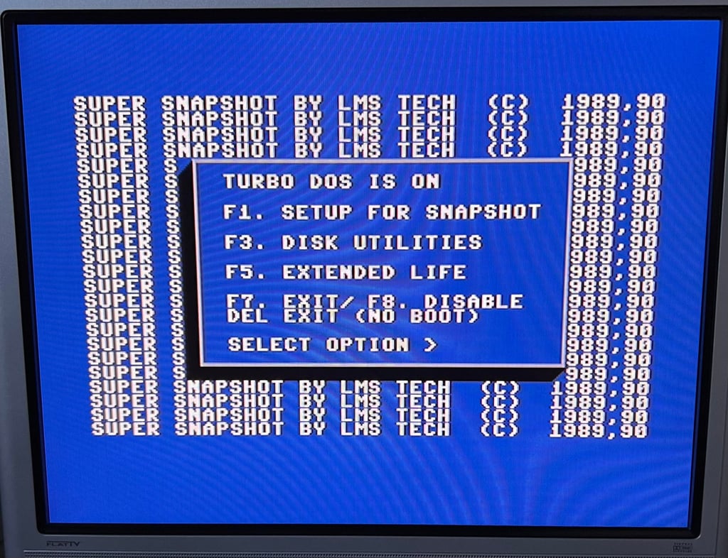
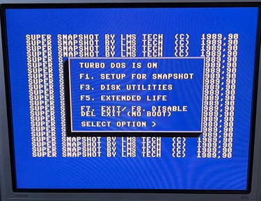
Last basic check before moving to more extensive testing is checking the cartridge. This is done by using the Super Snaphot V. Result is that the test is passed.
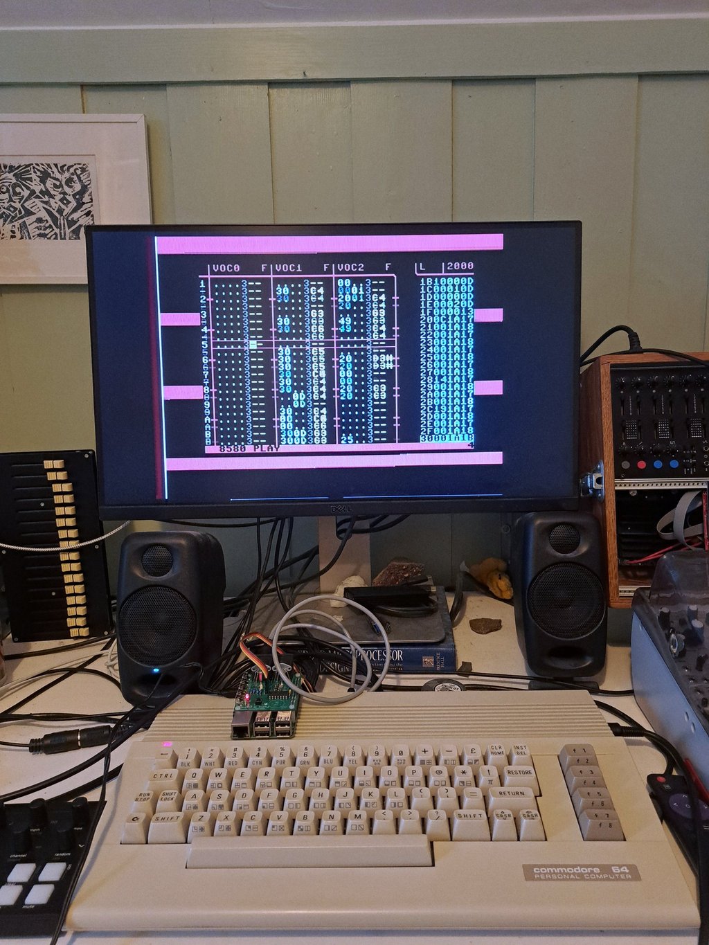
Extended testing
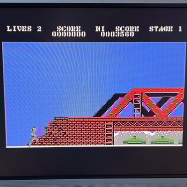
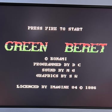
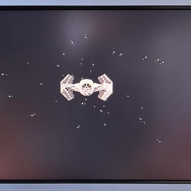
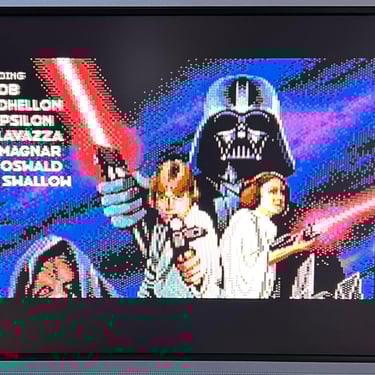
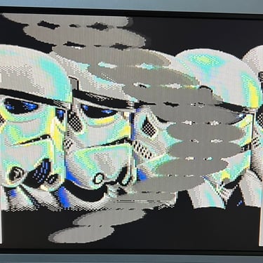
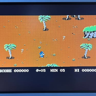
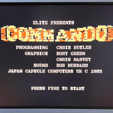
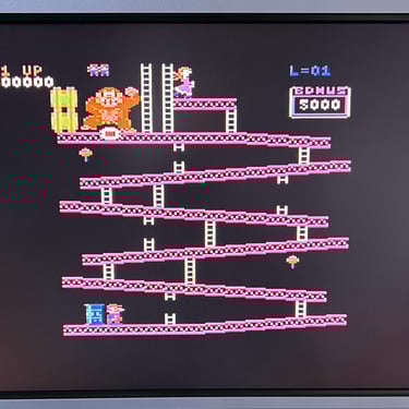
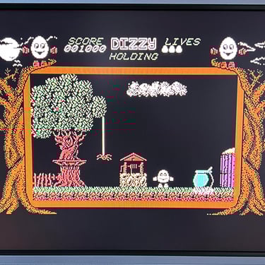
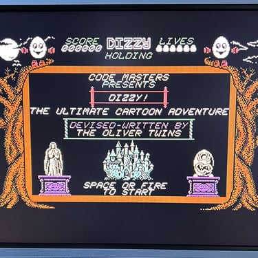
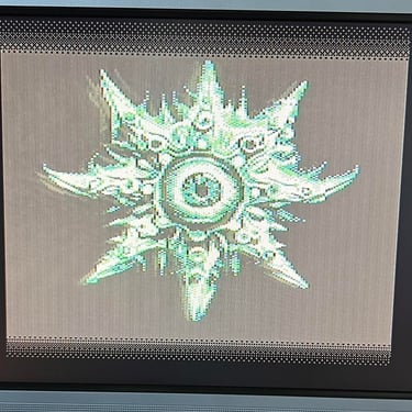
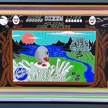
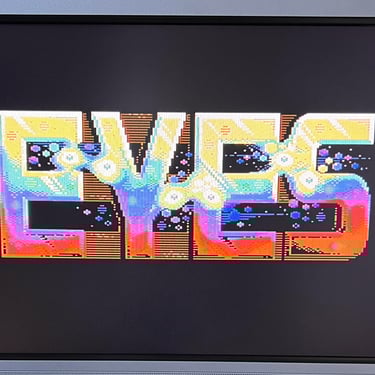
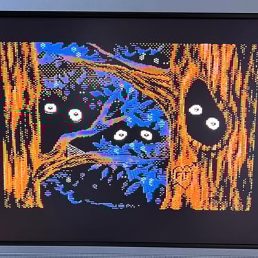
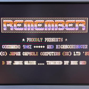
Knowing that the basic functionality of the machine works I continue the testing by using the Commodore 64 for normal operations; playing some games, watching demos, loading from datasette and floppy and using a cartridge. I can not find any issues with this machine. I also pay special attention to the video to make sure that there are no glitches in the graphics - I can´t see any abnormalities. Below is a gallery with pictures from the testing.


Final result
"A picture worth a thousand words"
Below is a collection of the final result from the refurbishment of this C64C. Hope you like it! Click to enlarge!


"Are you keeping up with the Commodore? 'Cause the Commodore is keepin up with you!"
Below is a picture of the Commodore 64 back at the customer´s home!
