

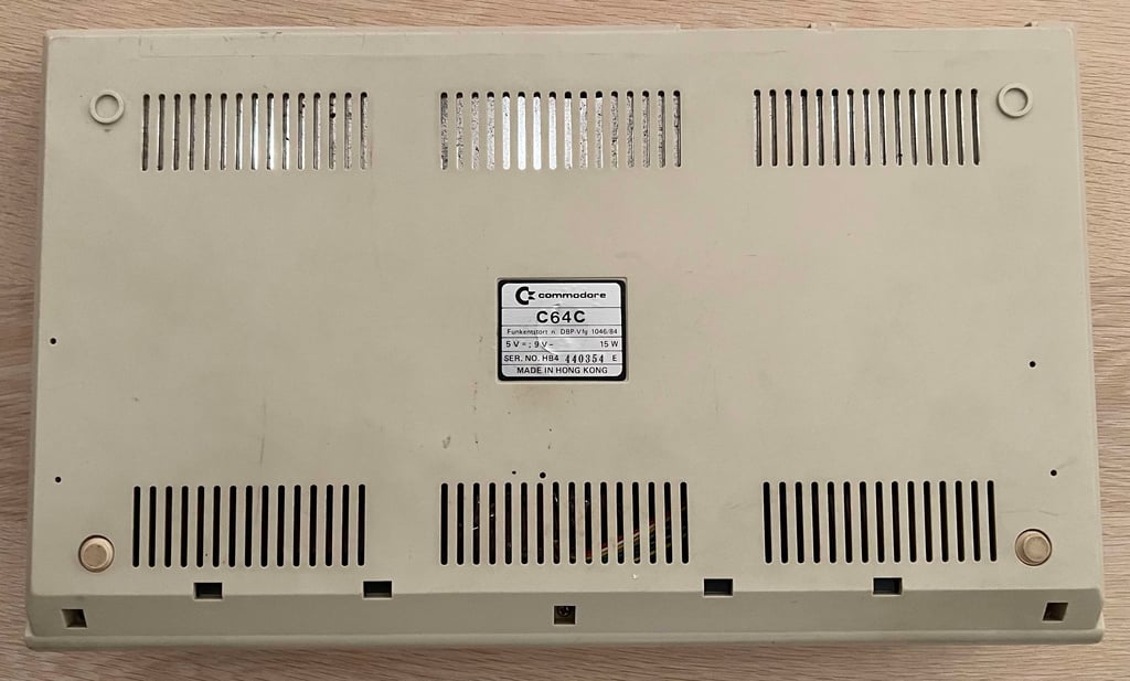
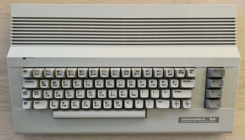
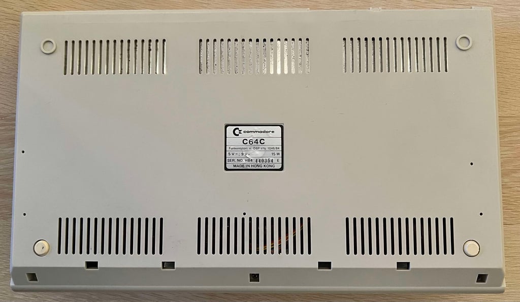
C64C [PAL]
Ser. No. 440354
Assy 250469
Artwork 252311 (REV 3)
Starting point
This C64C is in for some refurbish. As I understand it should be working, at least to some extent. There might be something which is marginal, but we´ll see during the refurbish.
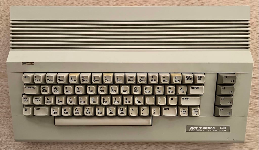
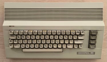
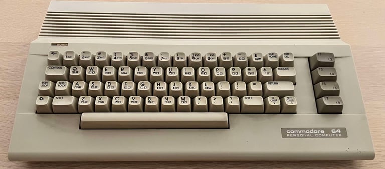
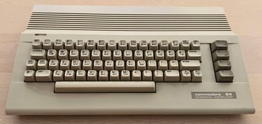
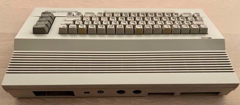
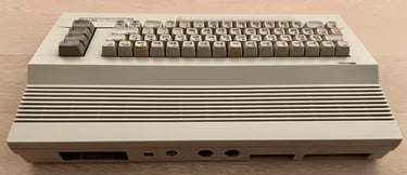
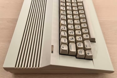
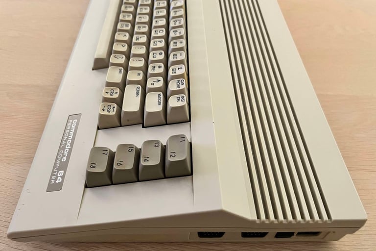
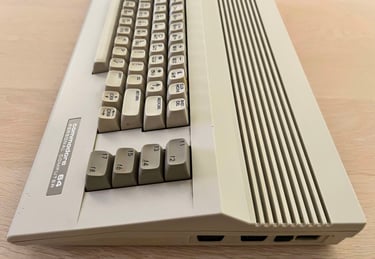
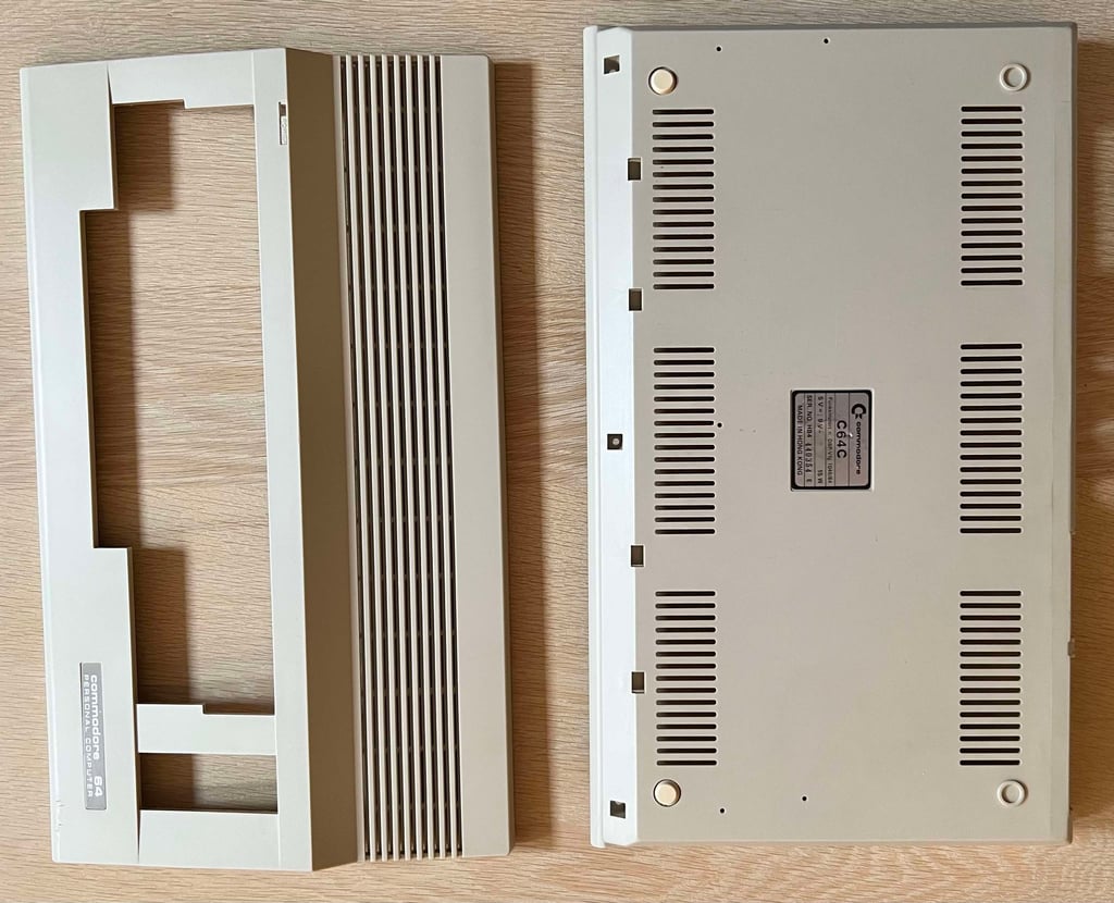
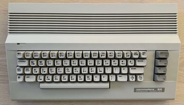
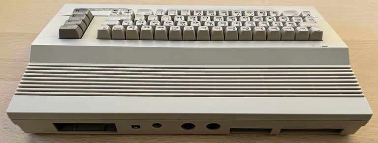
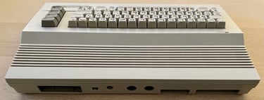
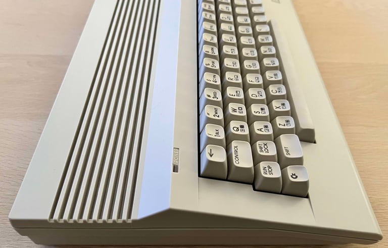
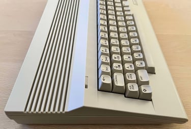
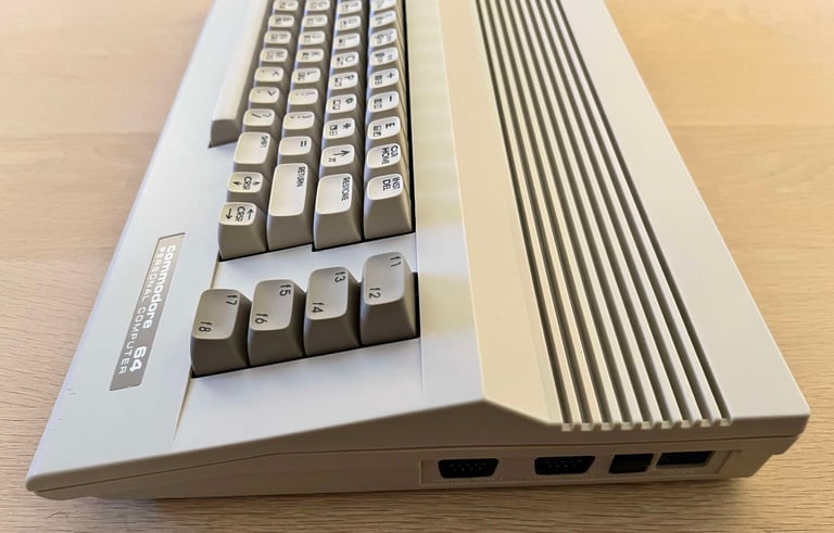
From the outside the machine looks to be in quite good condition. It is somewhat yellowed, especially some of the keys are partly yellowed, but not complete gouda cheese. There are some signs of use on the bottom right hand side which seems to be some small cuts or dents (?). And it is quite dirty. The pictures does not do it justice, there are more dust and grease than is visible from the pictures.

Refurbishment plan
The refurbishment plan for this C64C (order can vary and some of the tasks will be done in parallell):
- Clean and remove stains from the chassis
- Clean and restore the keyboard
- Refurbish main board (cleaning, checking, repairing, replacing capacitors etc.)
- Install modern RF-modulator replacement
- Verify operation by testing
The plan can be updated during the refurbishment process. Sometimes I discover areas that needs special attention.
Disassembly
First step of the disassembly is to - surprise! surprise! - to remove the three 3 x 8 mm Phillips screws at the bottom.

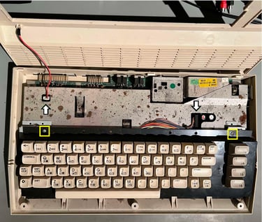
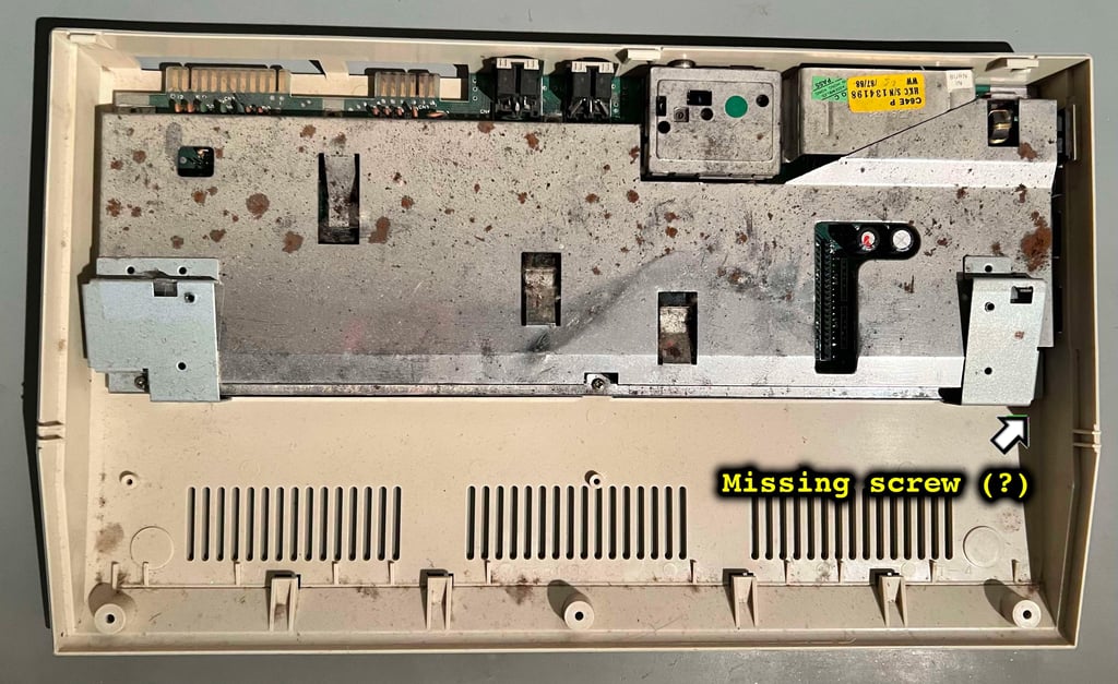
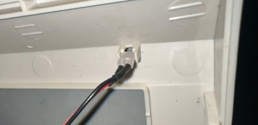
There are some corrosion on the RF-shield, but that is not to worry about. And some dust. But otherwise first impression is good. Next step is to remove the LED connector, the two machine screws holding the keyboard and the wide keyboard connector (see position of these in the picture above). With these out of the way the complete RF-shield is revealed. First thing I notice is that someone has been here before... The screw that should be in the right hand side corner is missing. Only the traces of it are remaining... Could it be that this machine has been repaired previously?

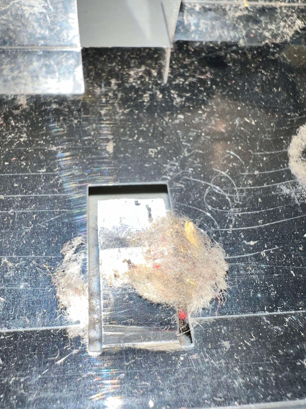
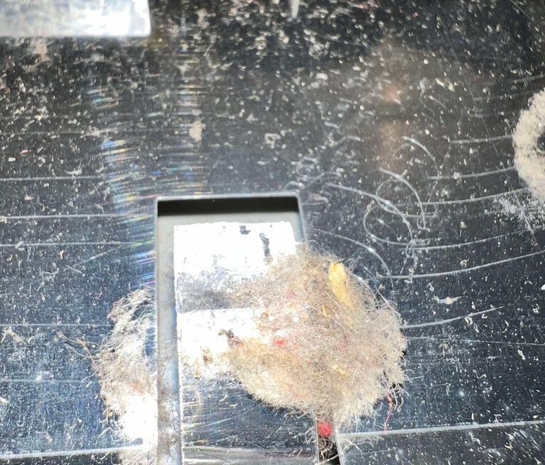
The remaining six screws are removed from the RF-shield (Phillips 3 x 8 mm), and the RF-shield is simply lifted away. And, holy moly, there is a lot of dirt and grease inside here. There are fluff everywhere. Also, the heatsink paste is completely dried out. It is hard to see the condition of the board before some serious cleaning is done.

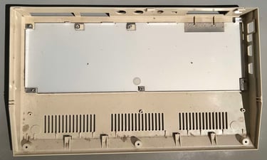
Now the mainboard is lifted from the bottom cover. Except from the dirt and grease it appears that the bottom cover, including the stand-offs, are in good condition. There are some corrosion on the bottom RF-shield, but this should not be a problem.

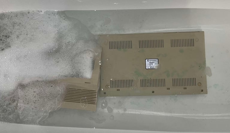
Exterior casing
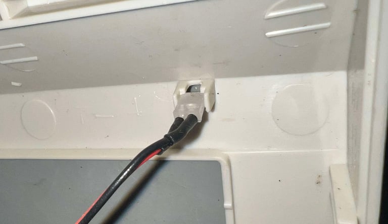
First things first; it is time for a long bath. Before the top- and bottom cover is placed in mild soap water for about 48 hours the LED is removed. With a flat small screwdriver the LED is loosened from the top cover.

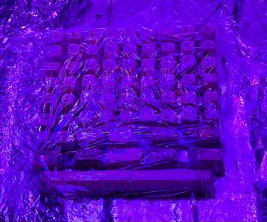
After cleaning the top- and bottom cover are retrobrighting. This is achieved by applying 12 % hydrogen peroxide cream on the covers frequently for a 12 hour period. The covers are wrapped in plastic cling film and exposed for UV light. Before retrobrighting the two small rubber feet are removed to prevent damage to these.
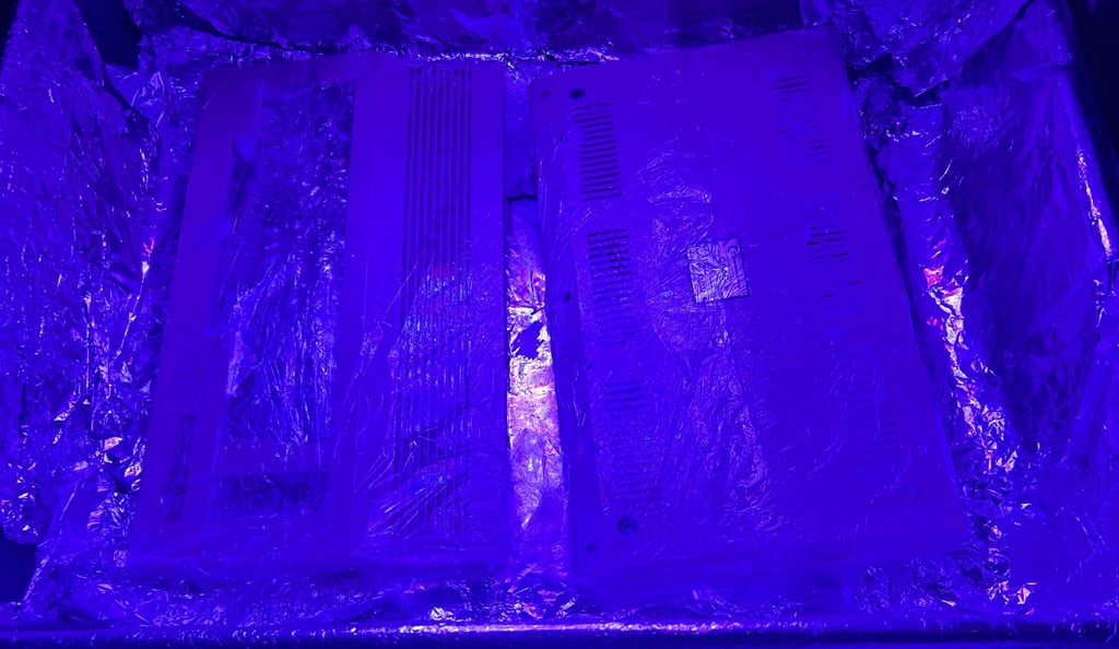
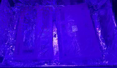
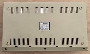
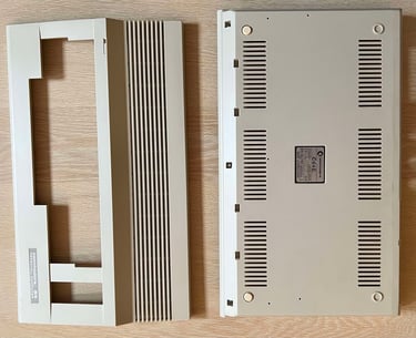
Both top- and bottom cover look very nice after retrobrighting. As mentioned there are some small dents/marks at the right hand bottom corner, but other than that the covers look pristine.
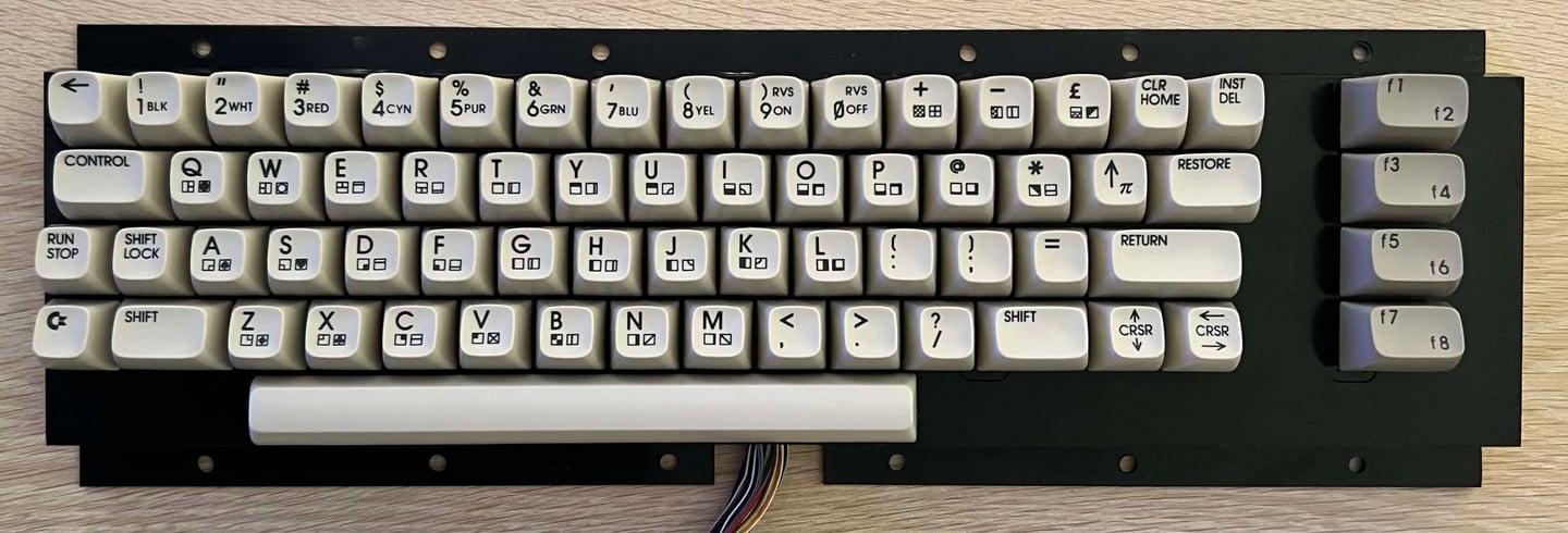
Keyboard
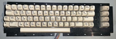
The keyboard is in quite good condition. There is quite some dust and grease, but this is to be expected. All keys appear to be undamaged, and also all springs feels ok. Some of the keys are partly yellowed so some retrobright is required. A detailed description on how to refurbish the Commodore 64 keyboard can be in the "HOWTO - Refurbish the C64 keyboard" article.

All the keycaps are removed with a special purpose puller. No keycap, plunger og spring were damaged during the operation. Note that the spring beneath the spacebar is slightly larger than the rest - so it is good practice to keep this in a separate bag during the refurbish.
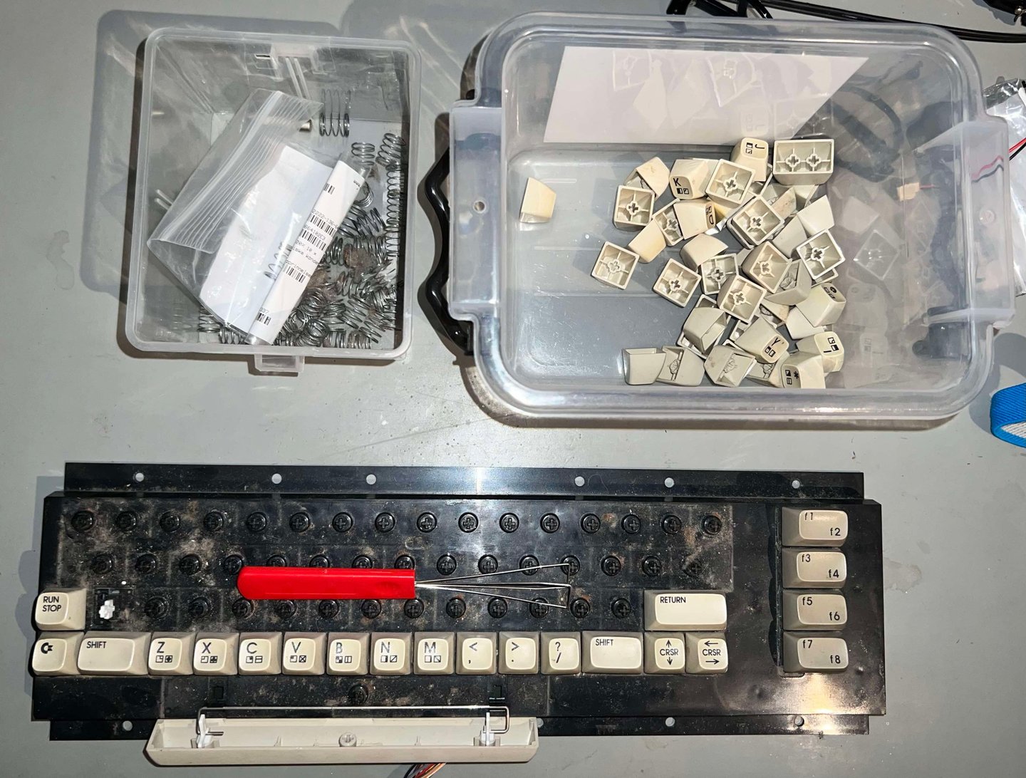
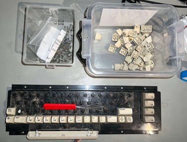
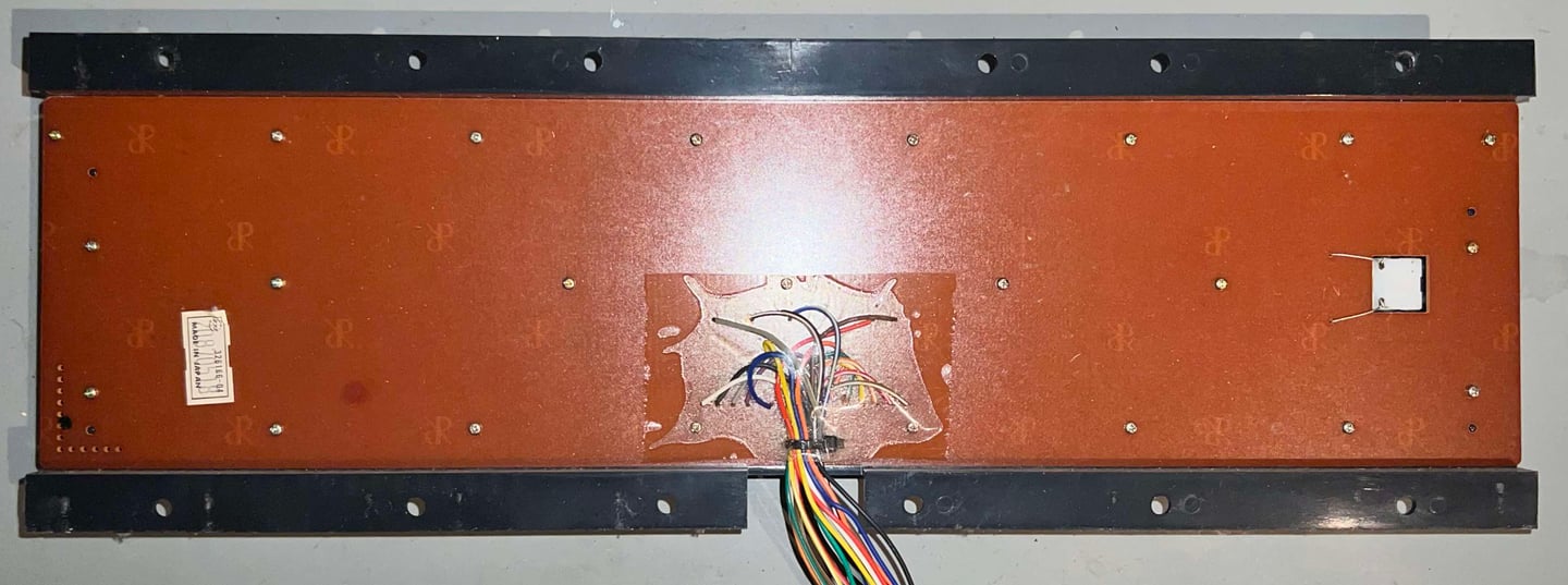
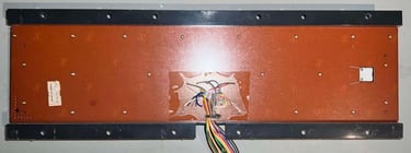
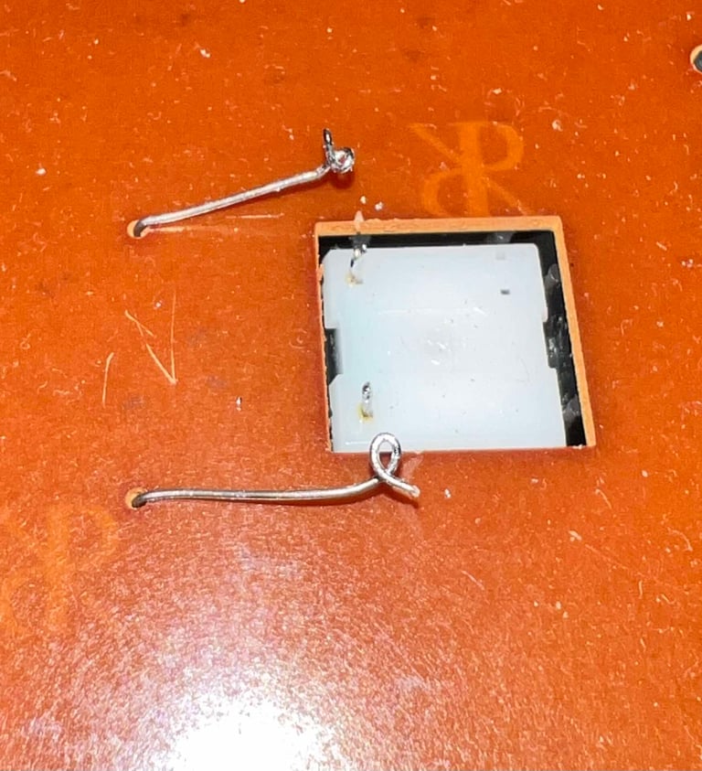
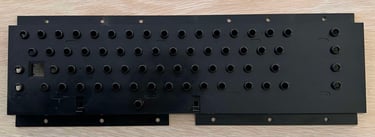
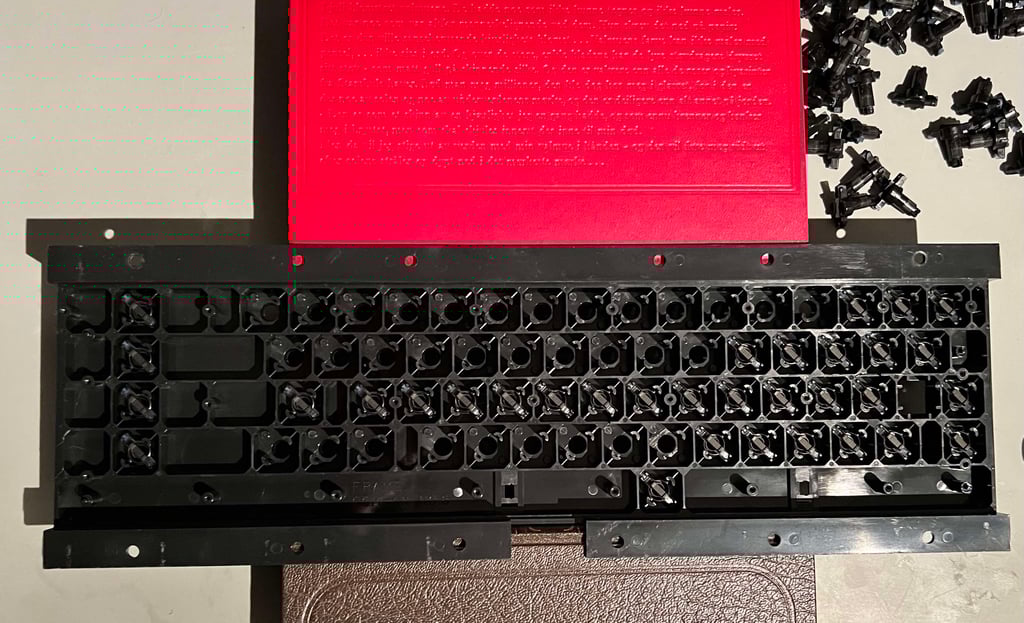
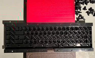
With all of the 66 keycaps out of the way, the PCB on the backside can be removed. But before all the million small screws holding the PCB to the keyboard bracket, the SHIFT LOCK key is desoldered. With a light push it pressed from the backside until it pops out. The SHIFT LOCK keys is cleaned with some isopropanol.
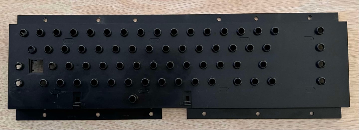
The plastic keyboard bracket is cleaned with some mild soap water. It looks brand new? Nice!
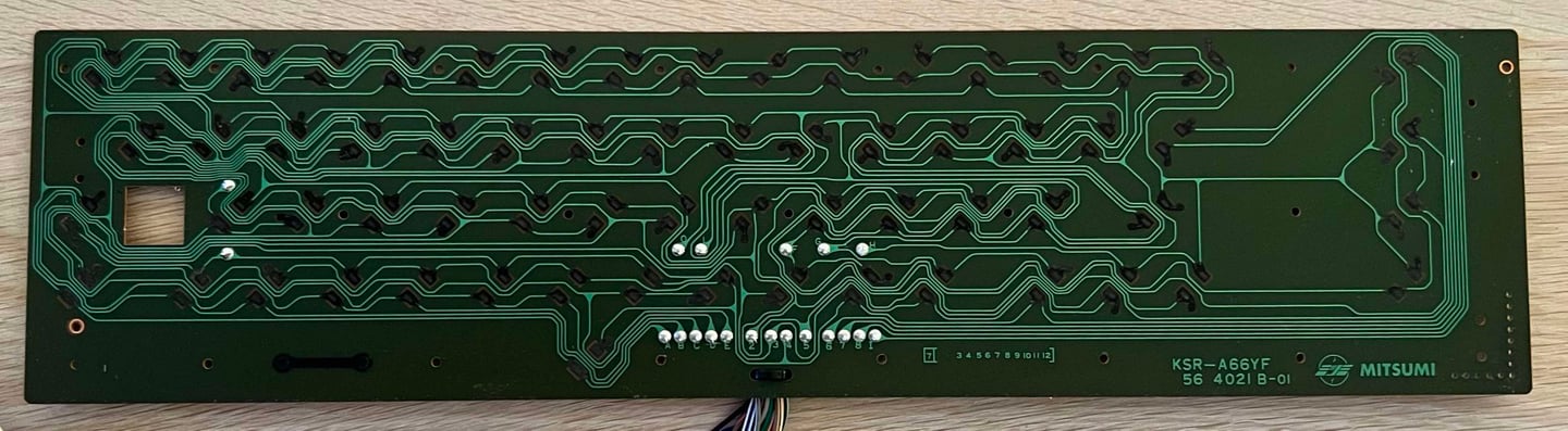
The keyboard PCB is KSR-A66YF 56 4021 B-01" which have carbon pads. To clean the PCB with the carbon pads some distilled water is used only. I try to avoid any isopropanol on the carbon pads unless it is strictly required as this can damage the pads.
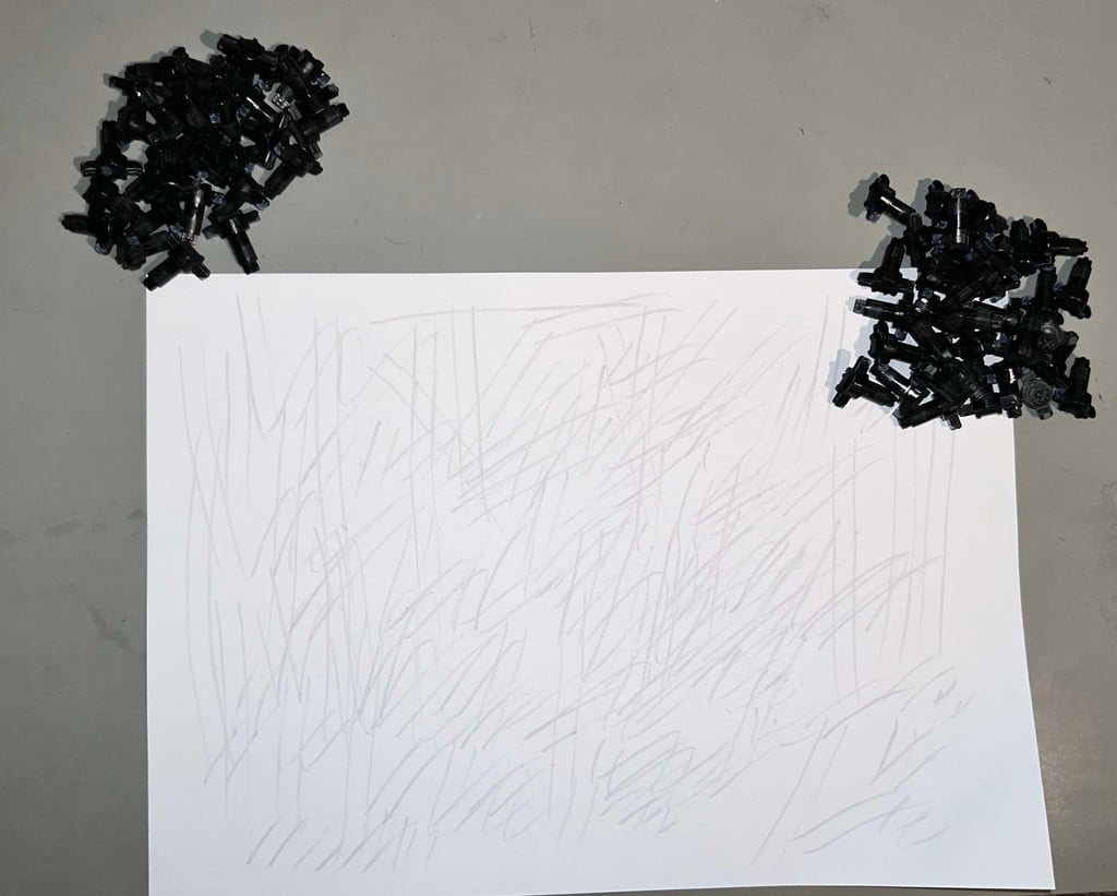
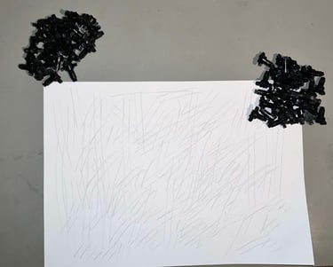
It is quite common that Commodore 64 keyboard has some "troublesome" keys. The reason for this is often that some dust and grease have gathered at the conductive rubber pads at the end of the plungers. To remove this, and to revive the plungers, all of them are carefully rubbed on a clean sheet of paper.
When re-assembling the plungers back in the plastic bracket it can help to lift it slightly from the table. With some books the bracket is hovering over the table top, making it easy to put all the 66 plungers back in.
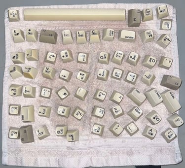
Cleaning the keycaps
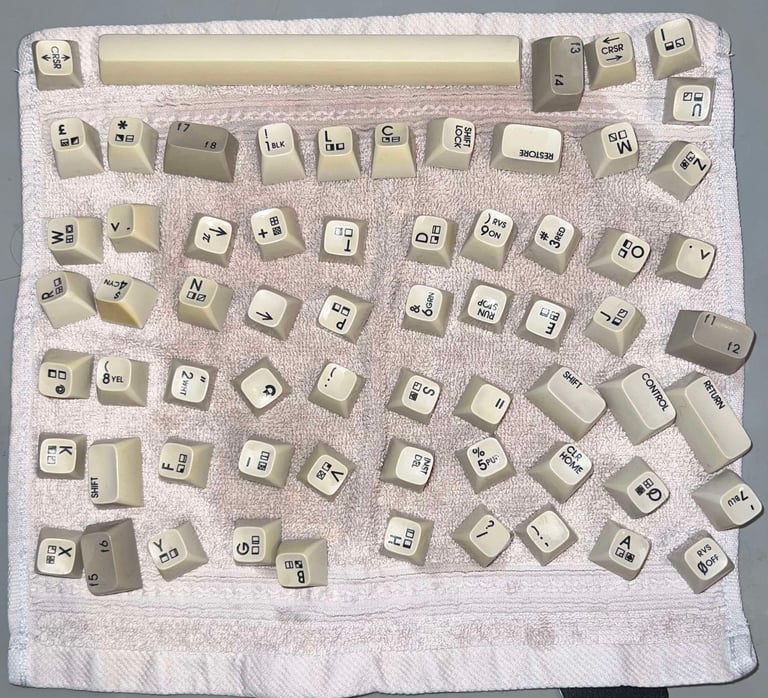
All the keycaps are placed in a box filled with mild soap water for about 48 hours. This will remove most of the grease and dust, and make the keycaps ready for retrobright. Below is a picture of the cleaned keycaps - before retrobright.
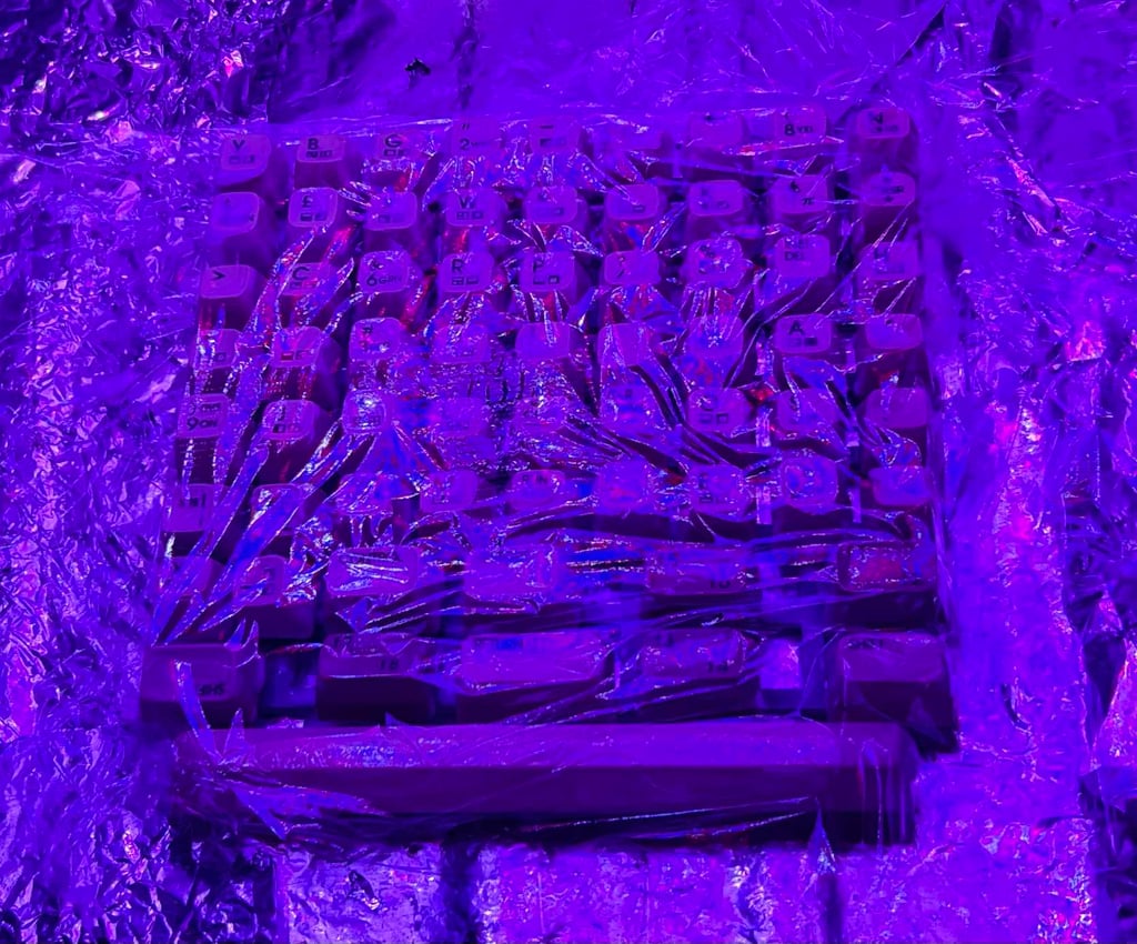
Retrobrighting the keycaps
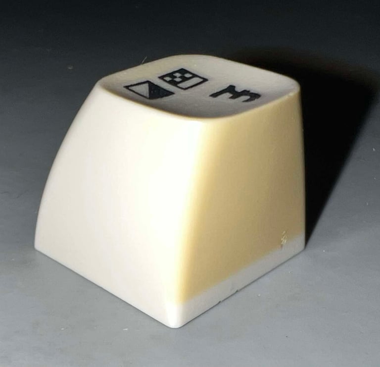
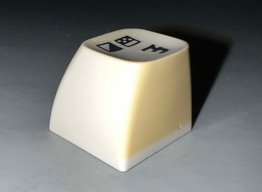
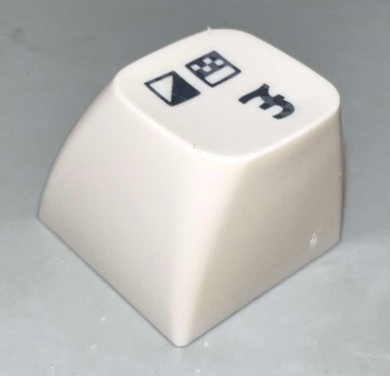
The keycaps are quite yellowed. The interesting thing is that not all the keycao have yellowed equally, and that each keycap have some sides more yellowed than other. All of the cleaned keycaps are placed on a 3D printed bracket.
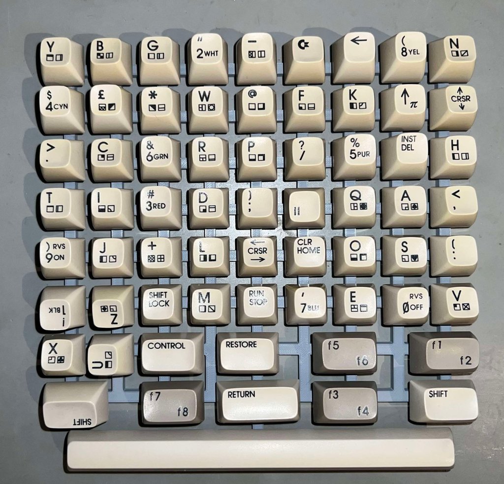
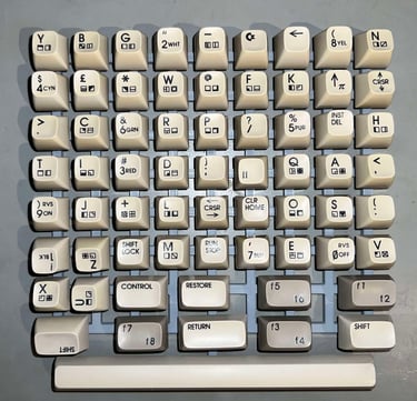
The keycaps are placed in the UV chamber, some 12 % hydrogen peroxide cream is applied to the keycaps. The keycaps are exposed to UV light for about 12 hours straight (note that during this period some fresh hydrogen peroxide cream is added regularly to the keycaps - and that they are covered with transparent cling film to avoid drying out).
After the 12 hours of retrobrighting the keycaps are way better. But there is still some yellowing. So another round of 12 hours of retrobrighting are done. But after a total of 24 hours the keycaps are "done"! Below are some pictures before and after retrobrighting.

Finally the keyboard is re-assembled. The result is very good I think!
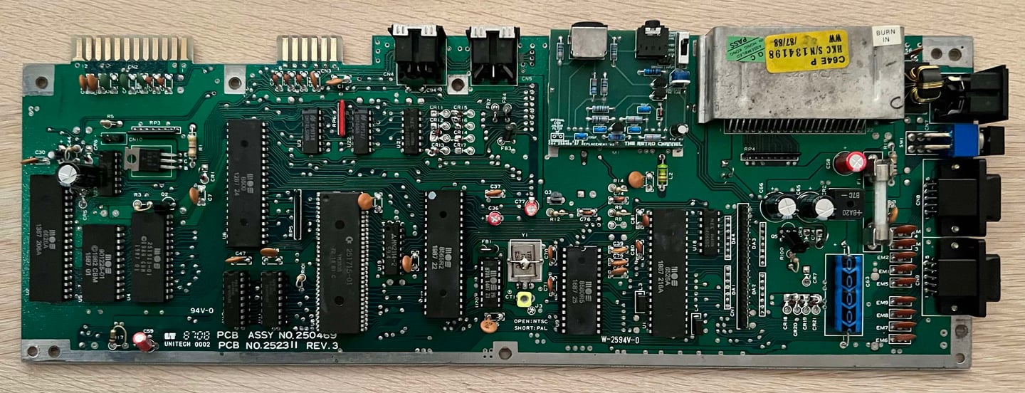
Mainboard
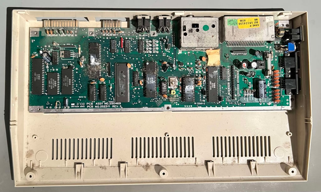
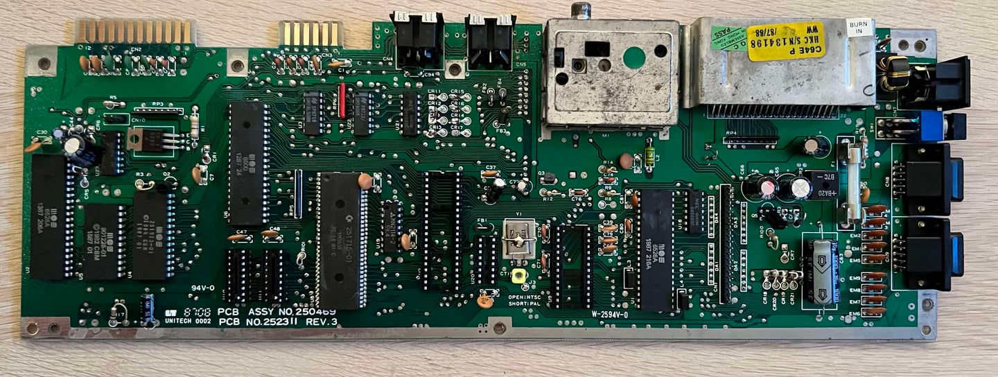
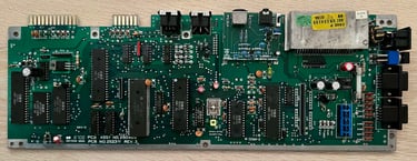
This PCBA mainboard is assy 250469 artwork 252311 (Rev 3) - aka a "shortboard". It appears to be complete, but oh my, it is so dirty.
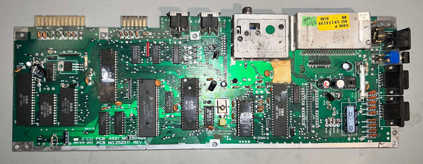
Cleaning
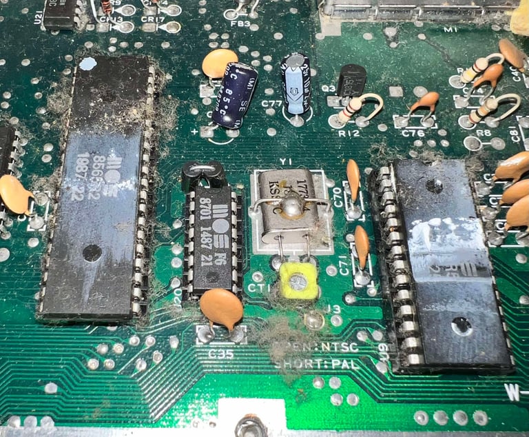
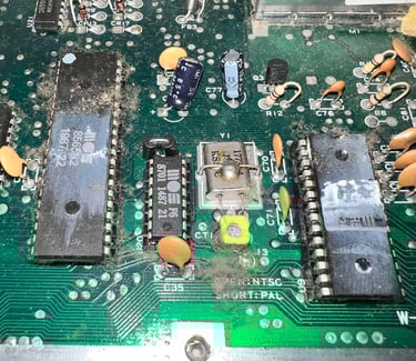
Before starting the visual inspection the mainboard it must be cleaned. As can be seen from the pictures below the dust and grease on the mainboard is substantial.

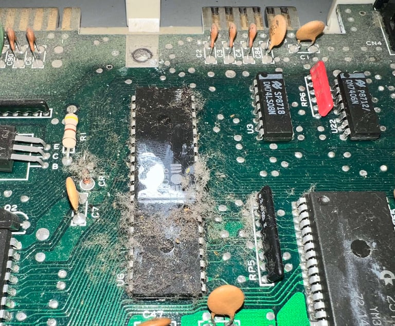

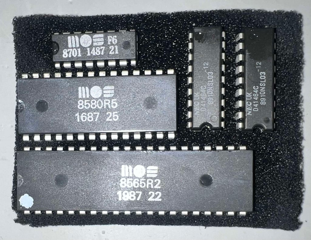
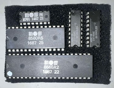
The socketed ICs are removed before cleaning. And the ICs are cleaned with some isopropanol using an old tooth-brush and some Q-tip.
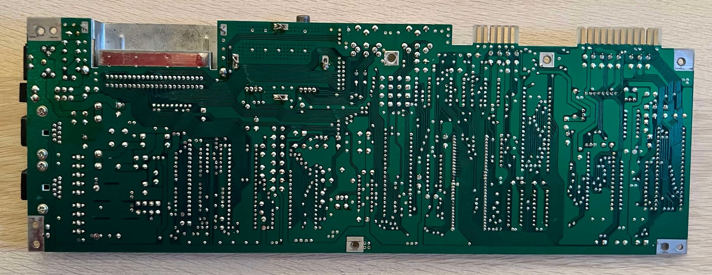
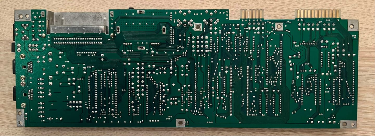
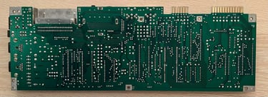
The mainboard is washed thoroughly with mild soap water. It is not a problem to wash the PCBA, but make sure that it is completely dry before power-on. Below is a picture of the cleaned, but not checked and refurbished, mainboard.
Visual inspection
The mainboard appears to be in good overall condition. I can´t see any damage or significant corrosion of any kind. The only thing I notice:
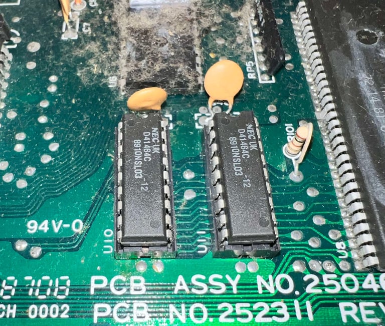
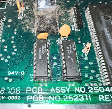
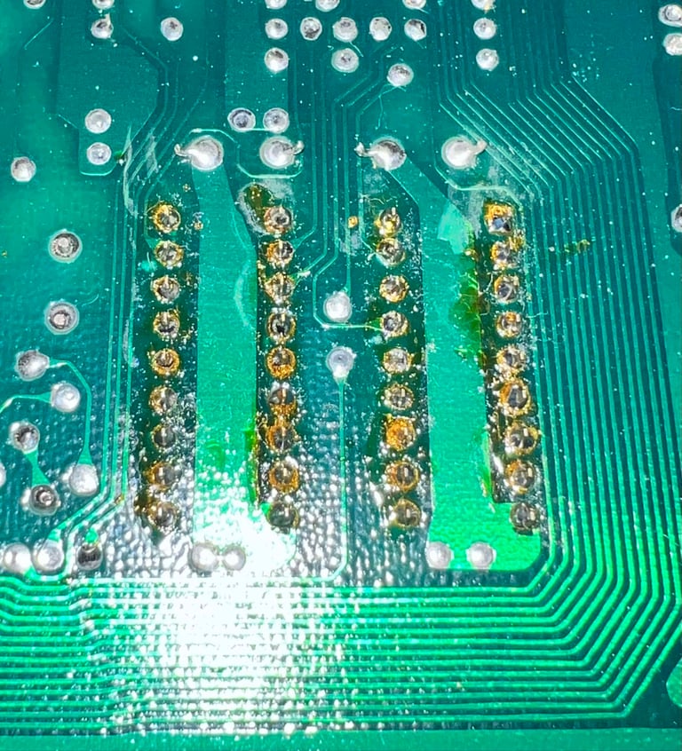
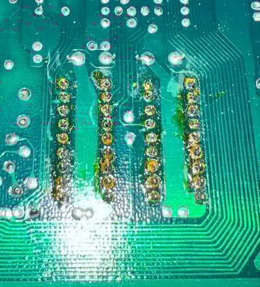
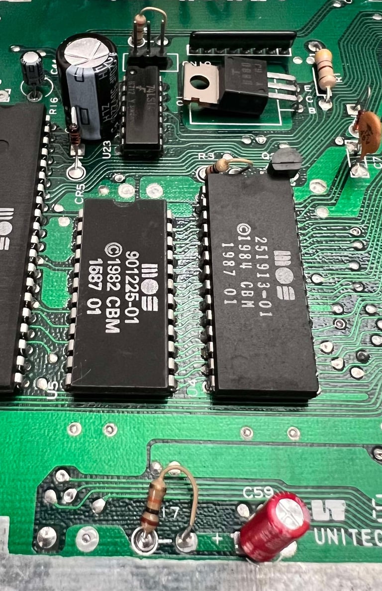
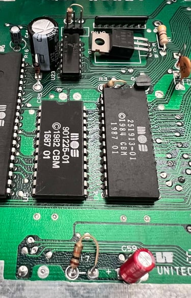
This mainboard has been repaired previously. Both RAM ICs have been replaced (and socketed). And this rework is not from factory. As can be seen from the picture below (taken before cleaning) there are plenty of flux residue left after the rework.
In the table below all the custom ICs are listed. And as can be seen from this table is that all original ICs were produced between week 12 to 19 of 1987 so I think we can assume that this Commodore 64 was produced in the late spring, or summer, of 1987. Also, I think it is a fair assumption that the C64C were repaired about two years later. The RAM ICs are from week 10 of 1989.
Initial testing
Before the machine is powered on for the first time a check for short circuit on the +5V DC and 9 V AC power rail is performed. This is easy to check at the user port – see the article of Checking the C64 voltages for the position of these. Luckily, there are no short circuit so it should be safe to power on.
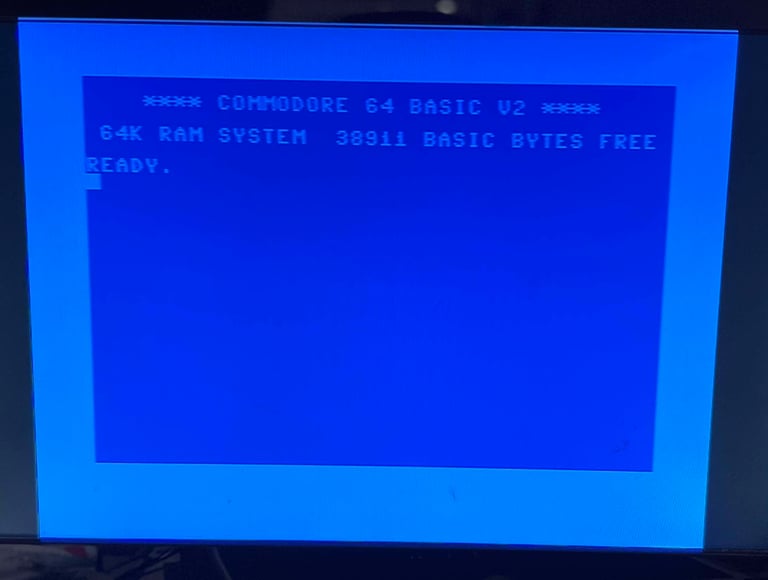
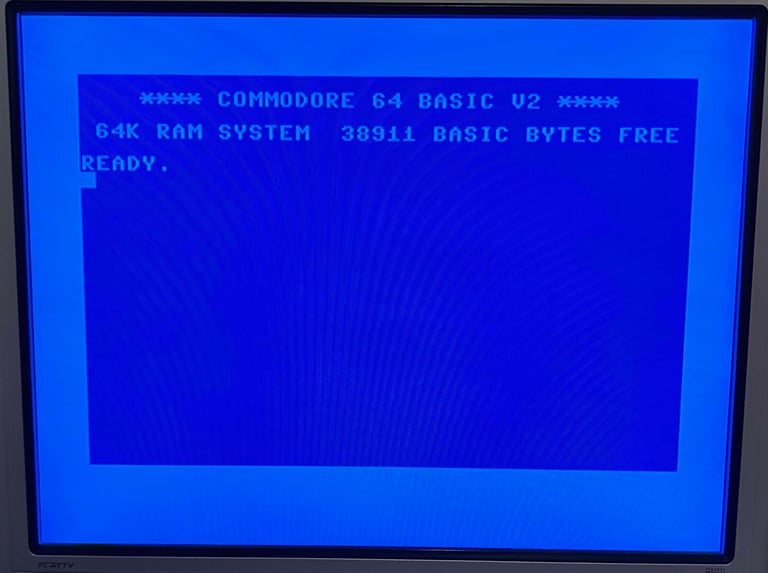
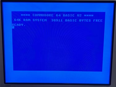
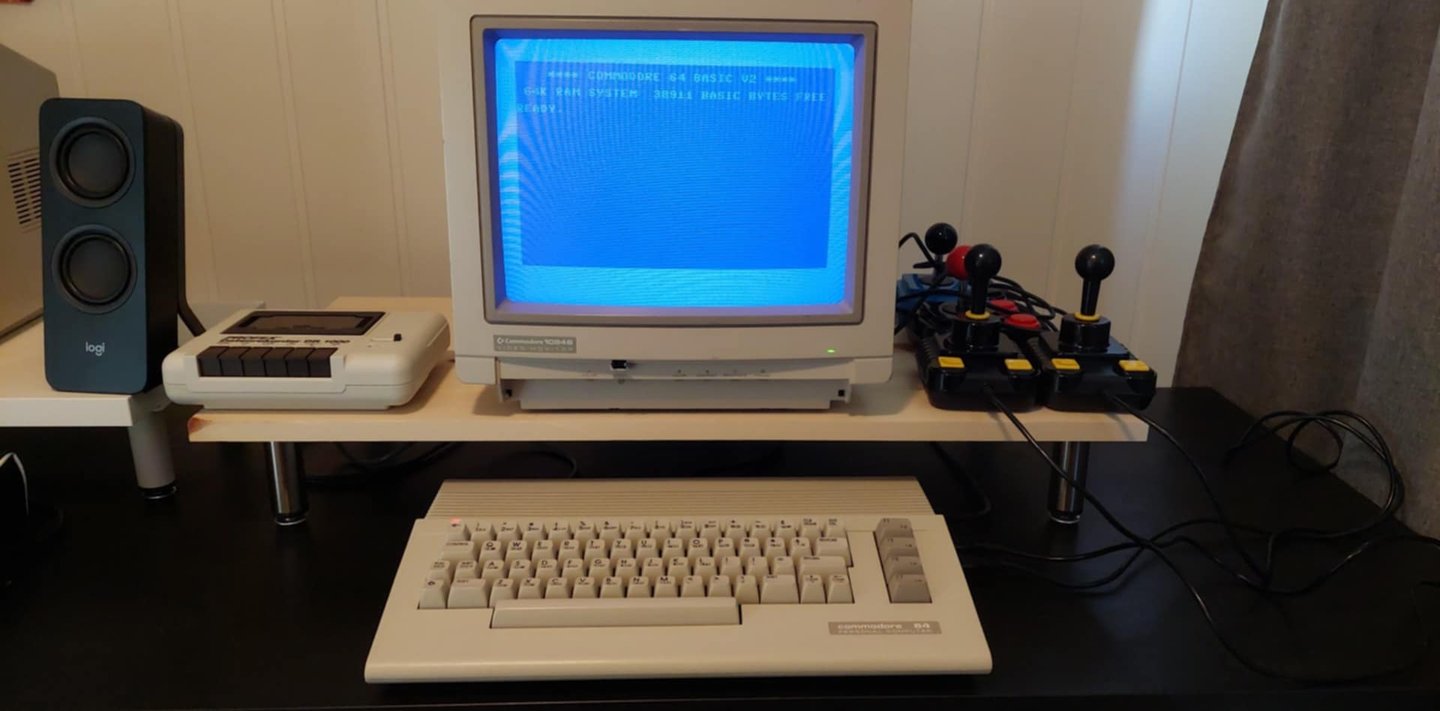
Powering on the Commodore 64 results in a: NORMAL BLUE BOOTUP SCREEN.

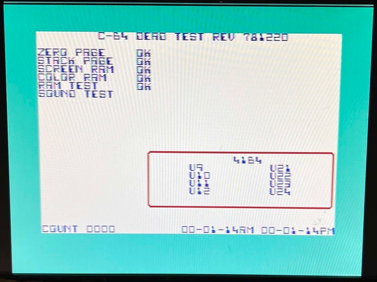
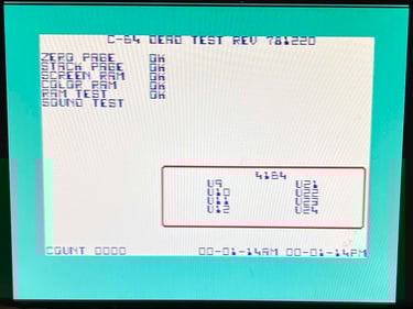
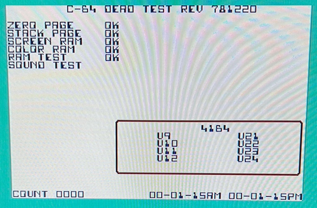
Next step in the initial testing is a test run with the Dead Test Cartridge. This will not reveal more complex issues, but it gives a good initial test of the major custom ICs. No errors were detected using the Dead Test Cartridge.
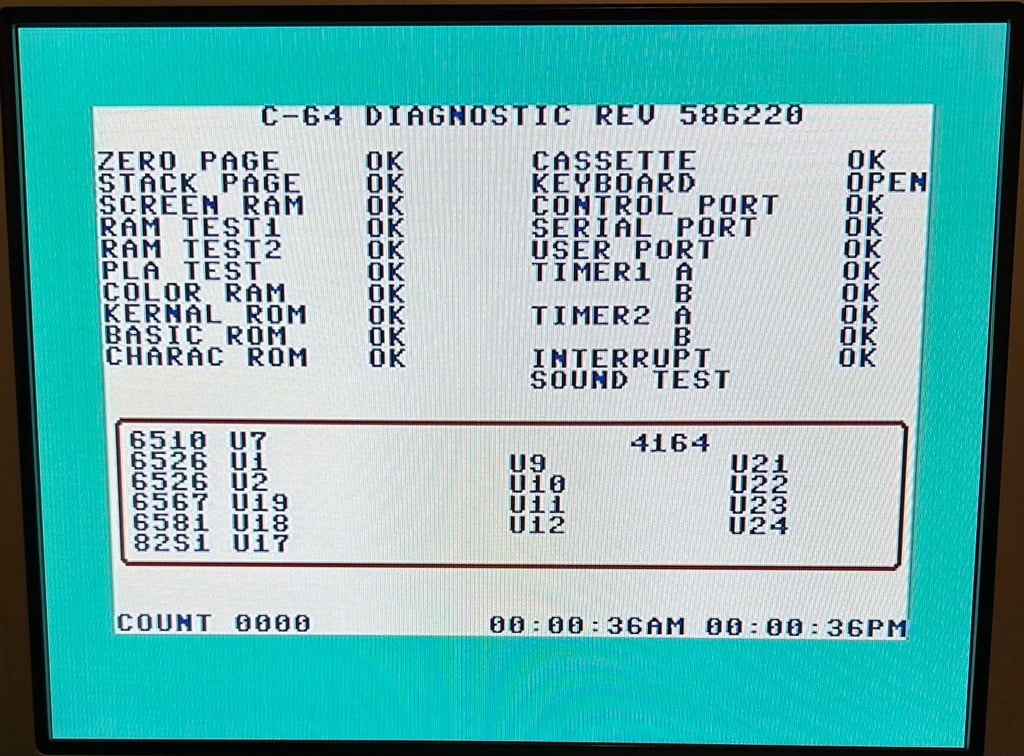
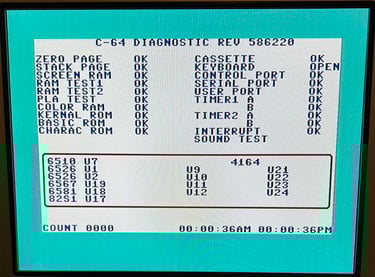
Running the diagnostics cartrigde
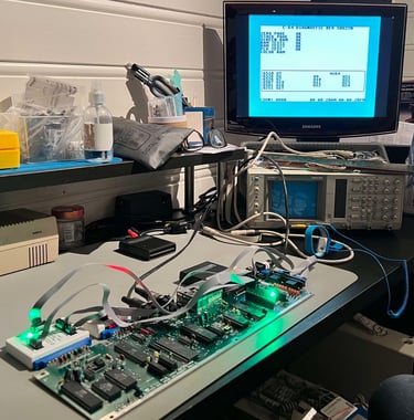
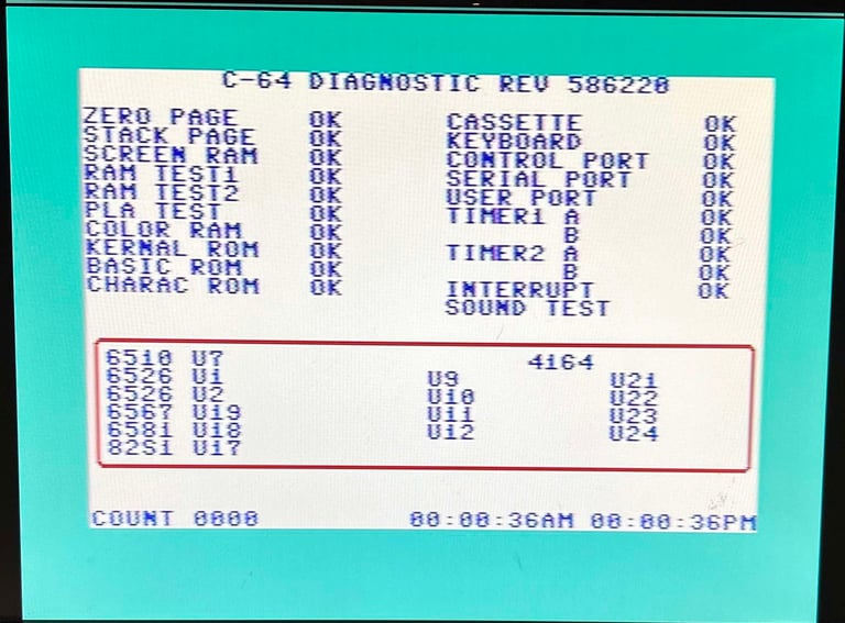
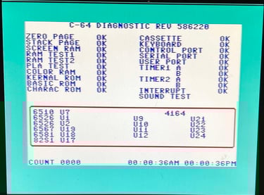
Knowing that the basic functions of the Commodore 64 works it is good practice to run the full diagnostics. This is achieved by running the software from the Diagnostics cartridge and connecting the harness. All tests pass. See pictures below.

Checking the voltages
For the Commodore 64 to work flawlessly all the different voltages need to present and within acceptable tolerances. A detailed article on the subject can be found in the HOWTO - Checking the C64 voltages. In the table below all the measures voltages are listed (this list will also be updated after refurbishment). All the required voltages are present and within tolerances.
Replacing the electrolytic capacitors
It is not strictly required to change the electrolytic capacitors on a Commodore 64, but it can be ok to do so as they are almost 40 years old. According to the capacitor list there are nine electrolytic capacitors on the Assy 250469 / Artwork 252311 / Rev 3 mainboard. All of these are replaced with modern quality capacitors. Note: some of the new capacitors have slightly higher voltage rating than the original which is fine (C65 25 V -> 50 V, C58 16 V -> 25 V and C43 16 V -> 50 V).
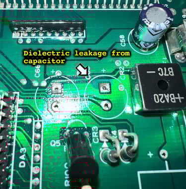
When removing the C65 I actually find some leakage from the capacitor which has damaged the top layer of the PCB. This is not so often I see on Commodore 64 machine as the capacitors seldom leak. Nevertheless, to make sure that the leakage does not damage the copper traces the area is repaired and cleaned (and neutralised with some vinegar). See pictures below.


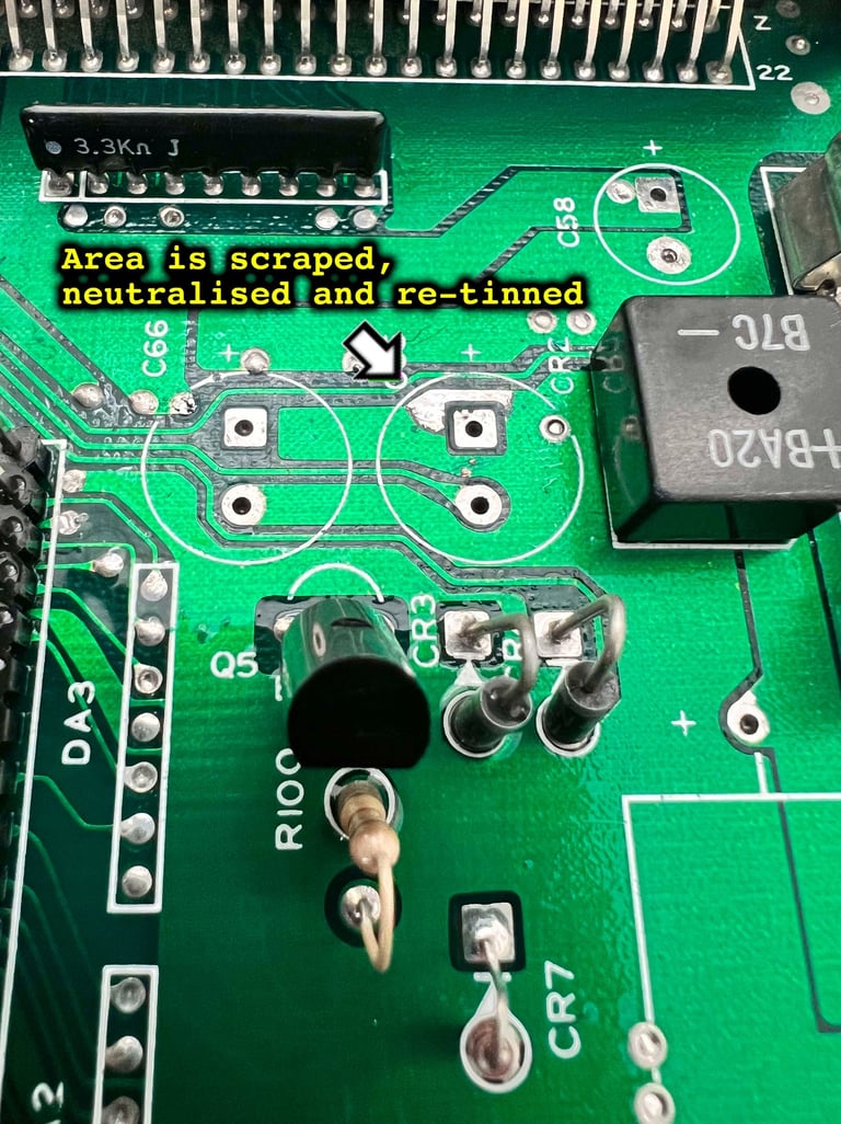
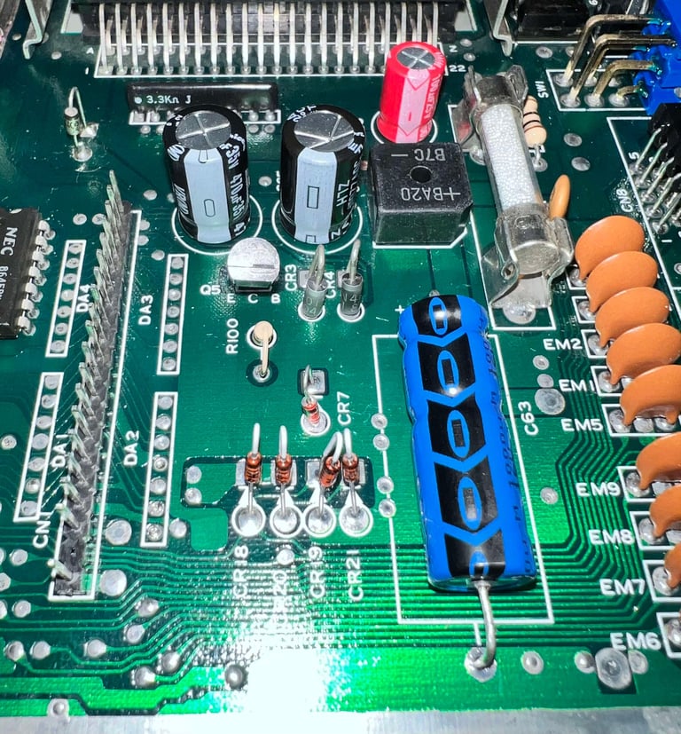
No pads or traces were lifted during the recap process. Below are some pictures of some of the new capacitors installed.

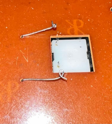
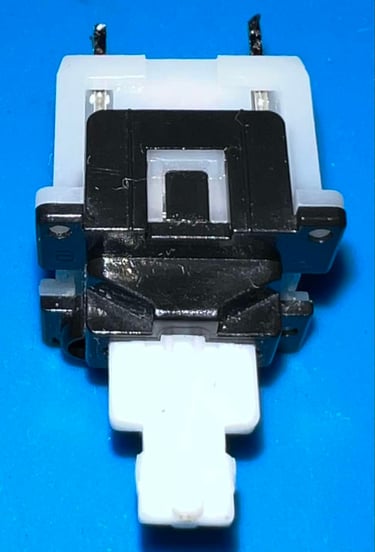
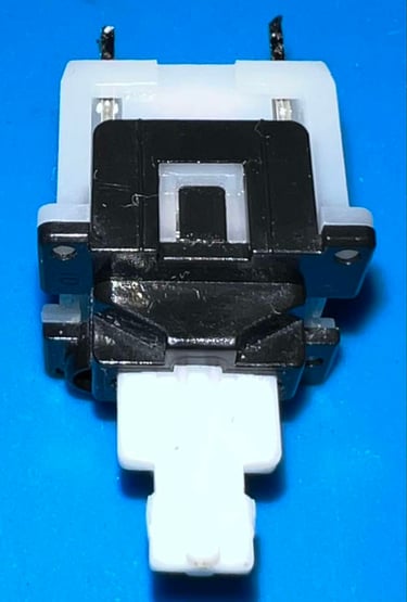
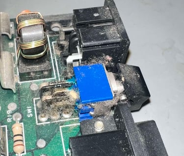
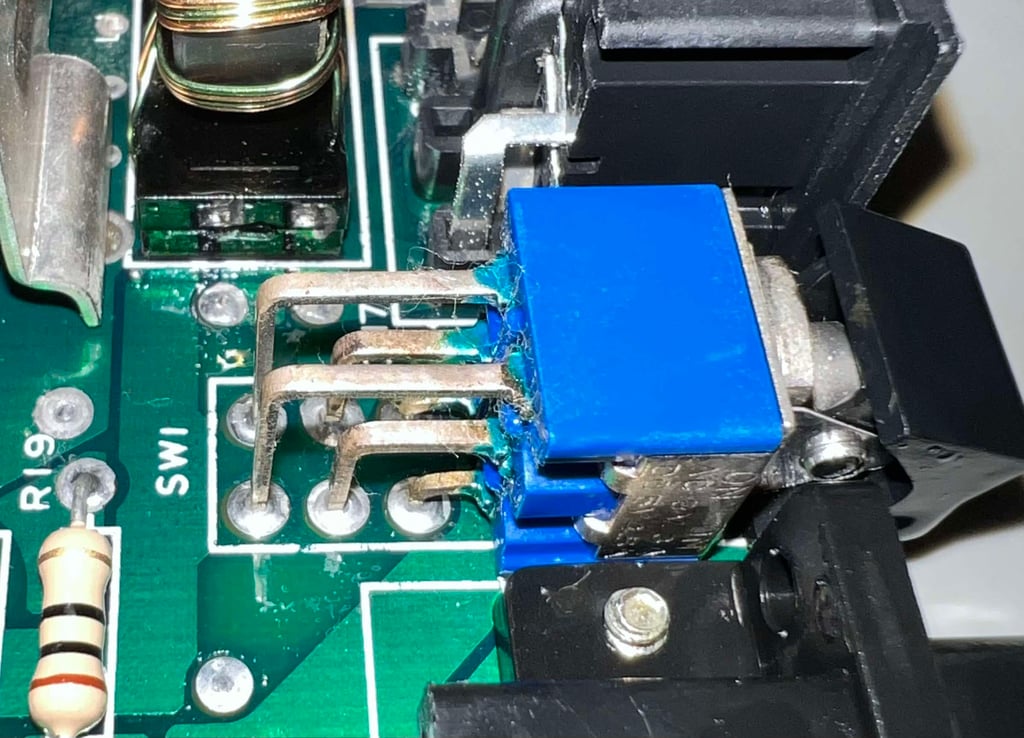
Cleaning the power switch (SW1)
Even after cleaning the mainboard, the power switch (SW1) is in need for further cleaning. The metal rods from the switch were heavily oxidised. With plenty of isopropanol and a Q-tip the rods are cleaned, and the switch looks as it should.

Replacing the RF-modulator
The analog video signal from the original Commodore 64 RF-modulator is not the best when it comes to picture quality. It is not that the picture quality is poor, but it can be improved.
One of the best RF-replacements are designed by The Retro Channel.
"The RF modulator in the C64 handles amplification and filtering for all video signals (including the ones on the C64 DIN connector). Unfortunately it does a very poor job and this is even more apparent with modern displays and upscalers, even CRTs with their inherent softening can reveal issues with the original RF modulator. One way to signifcantly improve the video output is to replace the RF modulator with a more modern and finely tuned solution, and why not add a few quality of life features while were at it."
The Retro Channels have designed what is probably the best analog RF-modulator available. And the design is open-source. I order the PCB from PCBWay and components are ordered from Mouser Electronics. Below is a picture of the fully assembled RF-modulator replacement.
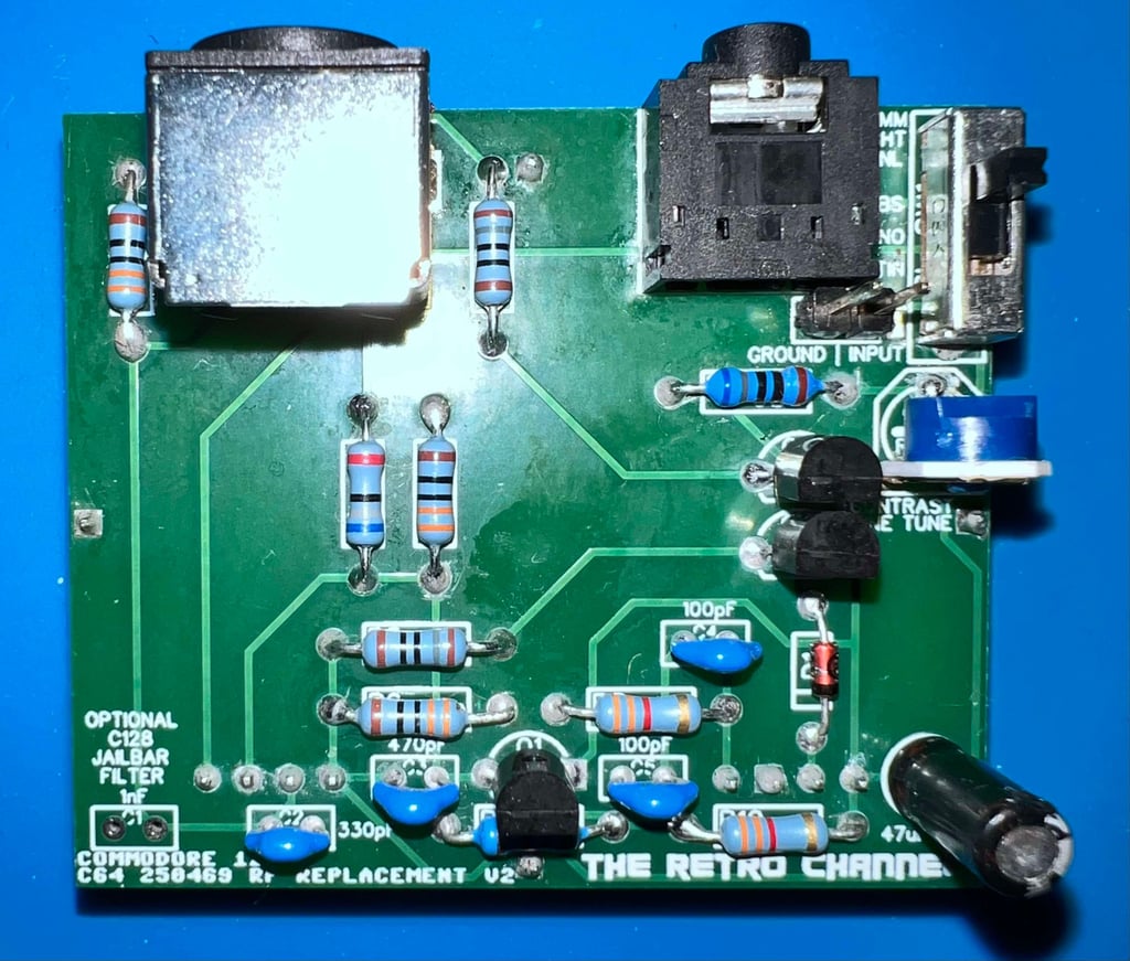

NOTE: There is a potentiometer which can be used to fine tune / adjust the video signal when in operation. Please check the The Retro Channels GitHub site for more details.
To install the new RF-modulator replacement the old RF-modulator needs to be desoldered and removed first. Desoldering the RF-modulator is not trivial, and it is important to be very careful not do damage traces or pads. Please see the HOWTO article "Desoldering the RF-modulator" for detailed information on how I desolder the modulator in general.
The RF-modulator is desoldered without any damage to traces or pads. See pictures below.


The new modern RF-replacement is installed and soldered to the mainboard.
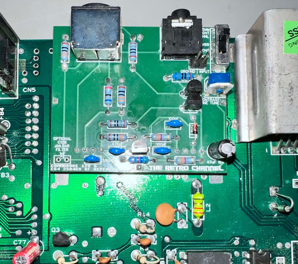
When the RF-modulator is installed both the S-video and audio connector are pre-aligned to fit the bottom cover nicely.
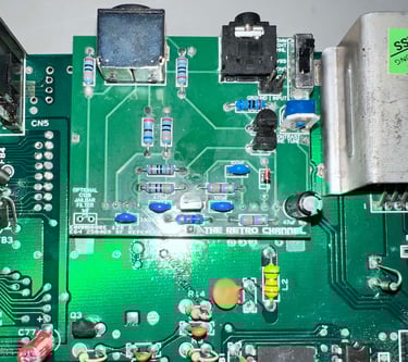
Below are some pictures of the mainboard after the refurbishment.
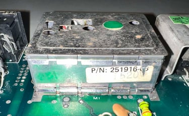
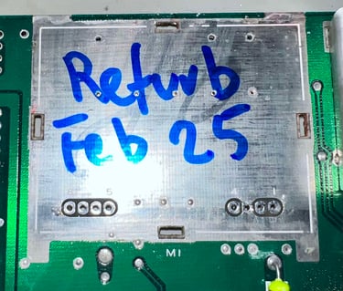
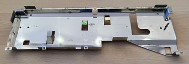
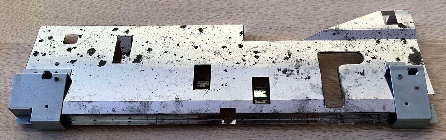
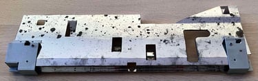
Preparing the heat shield
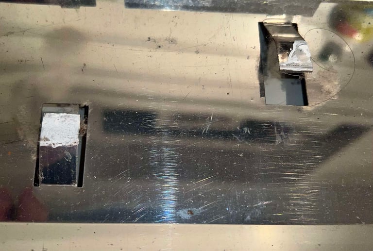
The C64C has a quite clever design; it combines keyboard stand-offs, RF-shield and a large heat sink all in one. But for the heat sink to function the metal tabs need to be clean with a thin layer of thermal paste. Without this the heat will be trapped and not be transferred effectively from the ICs to the surroundings. There are some surface corrosion on the top of the shield, but this is ok.
Below are some pictures of the shield before refurbish. As can be seen there is significant amount of grease and dust on the metal tabs, and the old thermal paste is completely dried out.
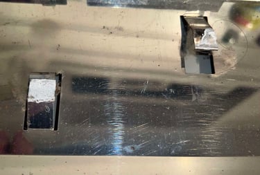
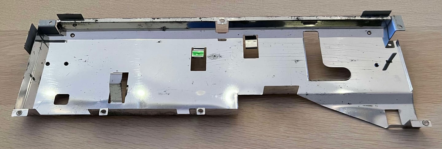
The shield is cleaned properly with isopropanol and a steel brush. The marks from the corrosion is still there, but that should not be a problem. It is quite normal that the top of these shields have corrosion marks, but that does not affect the machines function in any way.
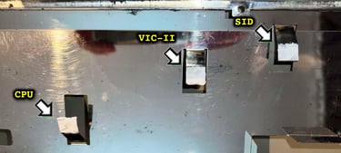
Adding thermal paste
As mentioned the old thermal paste was completely dried out (and full of dust). After the cleaning of the heat shield some new thermal paste is added to the three metal tabs. This will secure that the most valuable custom MOS chips have heat sinks. Note: when adding thermal paste it is wise to not add too much. The purpose of the thermal paste is to make sure that the tiny gap between the top of the IC and the bottom of the metal tab is sealed. If there is too much paste the effect is the opposite.

Testing
Proof is in the pudding - does it work?
Testing is done through three main stages:
Testing the basic functionality and chips
Testing the complete set of custom ICs and I/O ports
Testing by using the machine playing demos, games etc. accessed by both floppy and datasette to verify correct operation
Basic functionality and chips
First test is done using the Dead Test Cartridge. This test doesn´t test all the functionality of the Commodore 64, but it does test the basic functionality of the major chips such as the CIA #1/2, CPU, VIC-II, PLA, RAM and SID. As the picture shows below the test is passed.

Next test is to power the Commodore 64 to the blue boot up screen and also check the keyboard to make sure all keys works as they should. The test is passed; all keys works and 38911 BASIC Bytes Free.

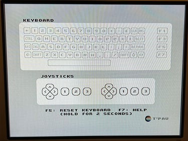
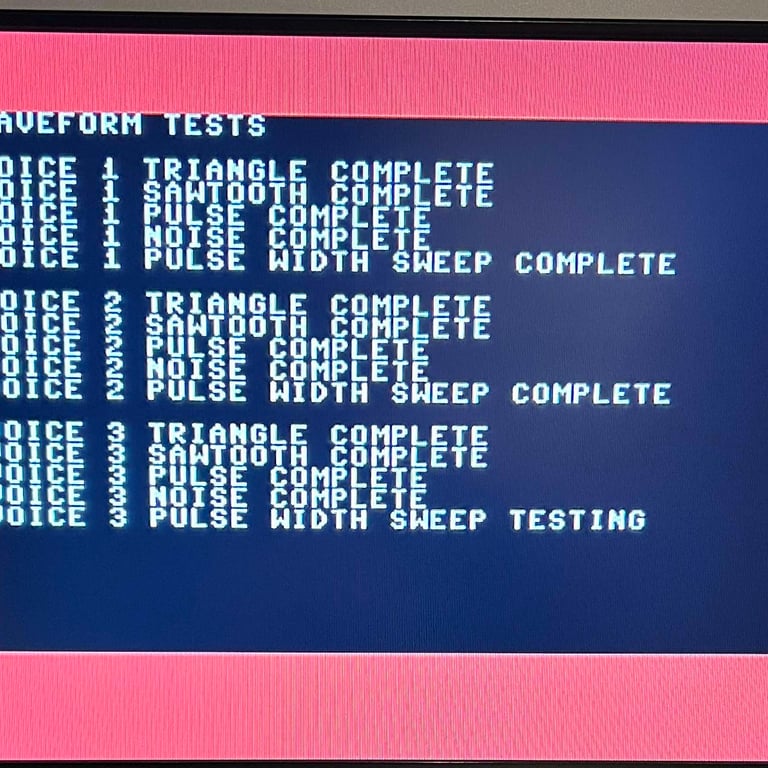
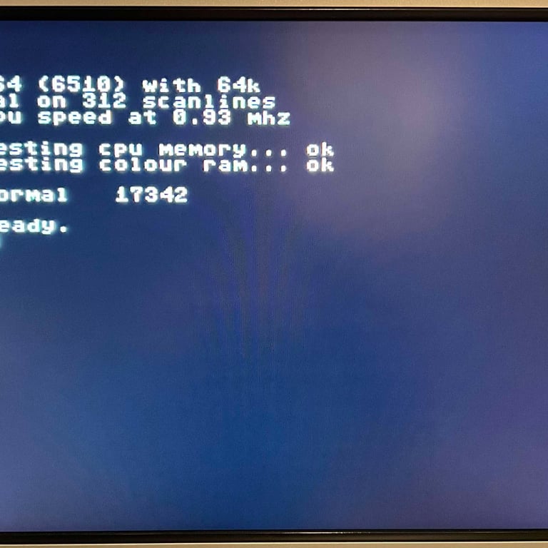
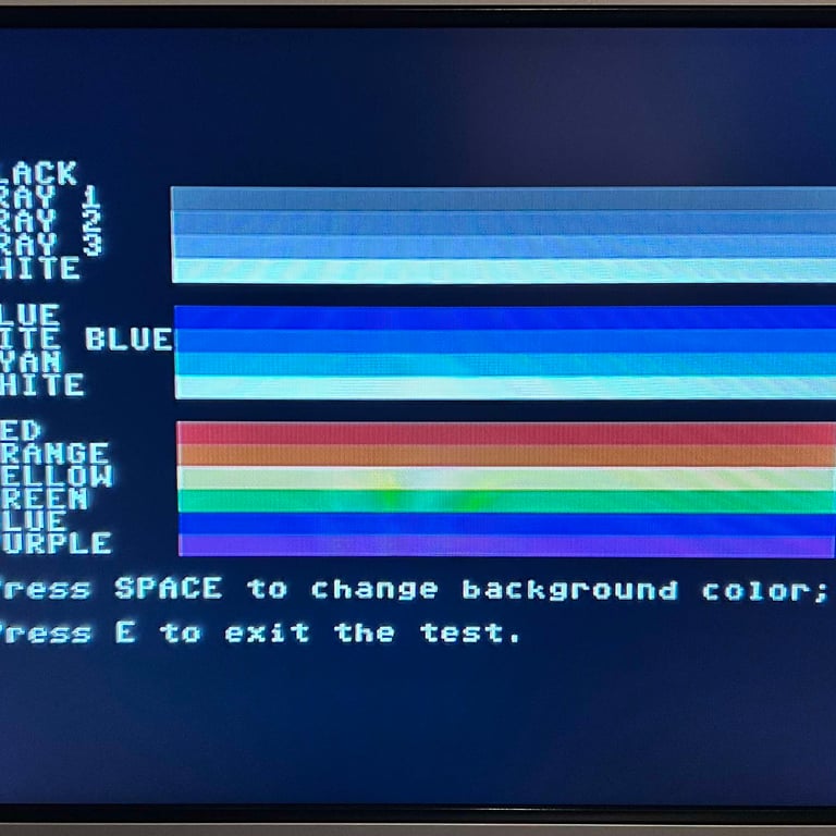
The basic functions of the VIC-II, SID and RAM is tested with 64 Doctor, Commodore 64 SID tester and MemTest64. Note that this is to be considered as basic functionality - more advanced (?) functionality such as sprite handling / collision detection / advanced audio will be tested later. But the basic tests pass without any detected faults (click to enlarge).
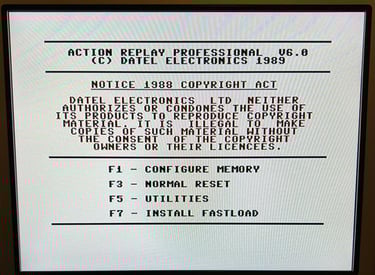
Last basic check before moving to more extensive testing is checking the cartridge. This is done by using the Action Replay VI. Result is that the test is passed.

Diagnostics test with harness
To test all the custom ICs, and I/O ports, the Diagnostics cartridge is used. The Diagnostics cartridge is very valuable when the complete test harness i installed as in "everything" is tested formally. As can be seen from the picture below, no issues are identified.
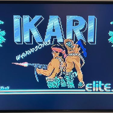
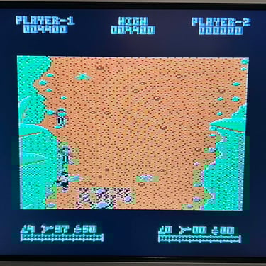
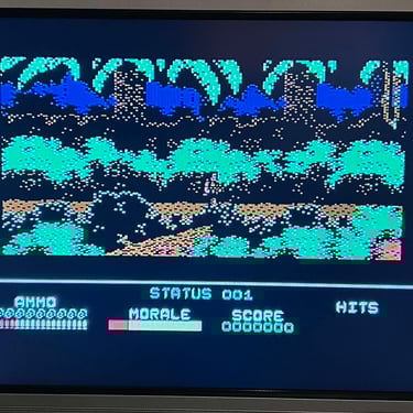
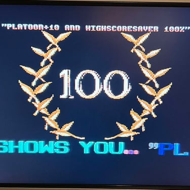
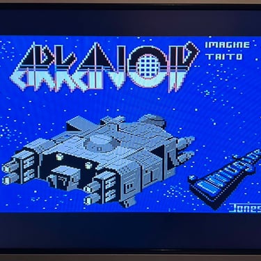
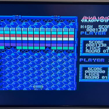
Extended testing
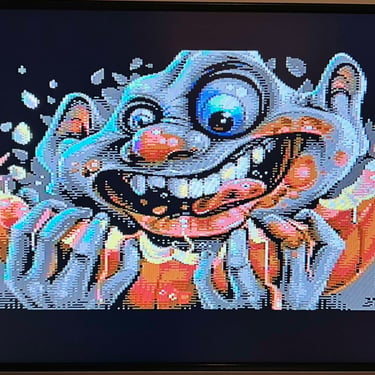
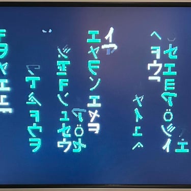
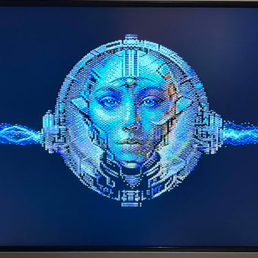
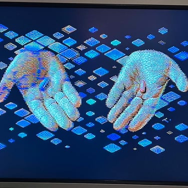
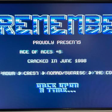
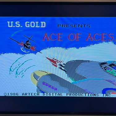
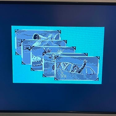
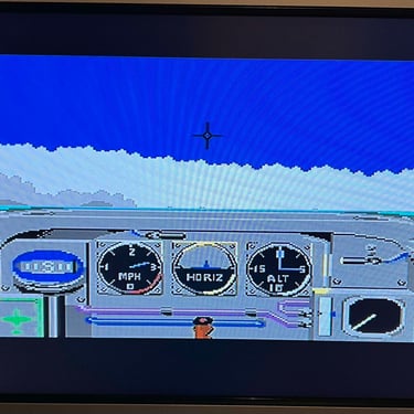
Knowing that the basic functionality of the machine works I continue the testing by using the Commodore 64 for normal operations; playing some games, watching demos, loading from datasette and floppy and using a cartridge. I can not find any issues with this machine. I also pay special attention to the video to make sure that there are no glitches in the graphics - I can´t see any abnormalities. Below is a gallery with pictures from the testing.


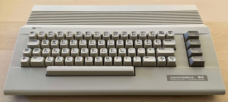
Final result
"A picture worth a thousand words"
Below is a collection of the final result from the refurbishment of this C64. Hope you like it! Click to enlarge!
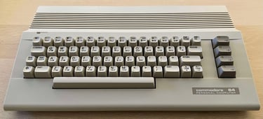

"Are you keeping up with the Commodore? 'Cause the Commodore is keepin up with you!"
Below are some pictures of the Commodore 64 back at the customer´s home!
