

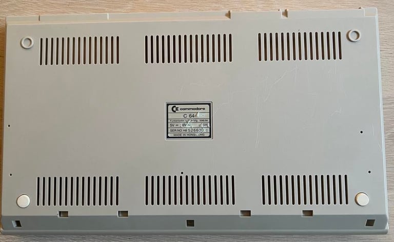
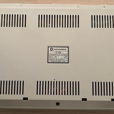
C64C
Ser. No. 526680 Assy 250466
Refurbishment plan
This is a C64C which I´ve had for some time and done some refurbishment already - but not documented unfortunately. But please trust me when I write what I´ve done.
This is my favorite version of the C64! Why? Because it combines the best of two worlds; outside it have the new chassis design and the "old" exclusive keys with symbols printed in front. And inside it have the old longboard with the enhanced SID chip (MOS 6581R4AR) with ‘Advanced Resonance’ and the highly acclaimed MOS 6569R5 VIC-II chip. Well, at least I hope they are in there...
Now, to the plan (some of them in parallell):
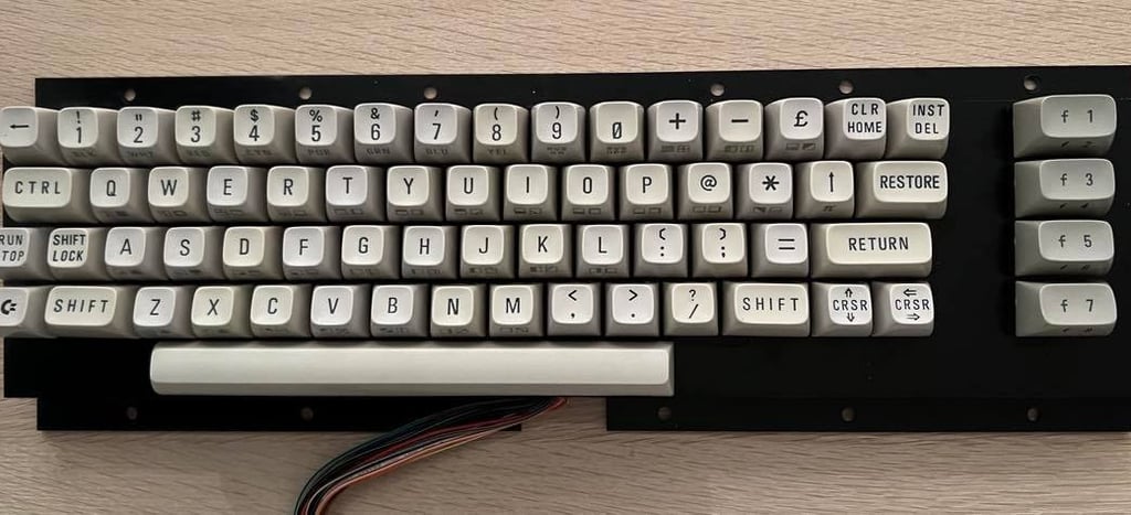
Clean and restore the keyboard
Clean and remove stains from the chassis
Refurbish main board (cleaning, checking, repairing, replacing capacitors and voltage regulators etc.)
Recap RF-modulator
Verify operation by testing
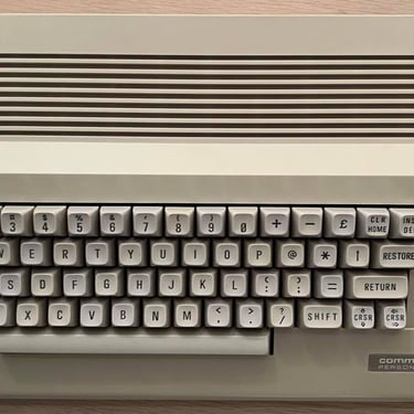
Keyboard
All the keys are removed and cleaned with mild soap water. Again, these are my favorite keys. White keys with the symbol printing in front. Some of the keys are quite yellowed so I place them in a plastic bag filled with 12 % hydroperoxide cream. This was done during the summer of 2022 so the plastic bag was placed outside to get direct UV-light on a sunny day. I don´t quite remember for how long this was, but I guess it was probably the whole day. The plastic bag is turned regularly (about every 45 minute).
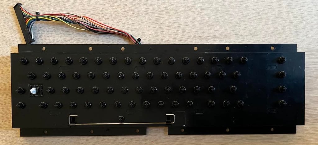
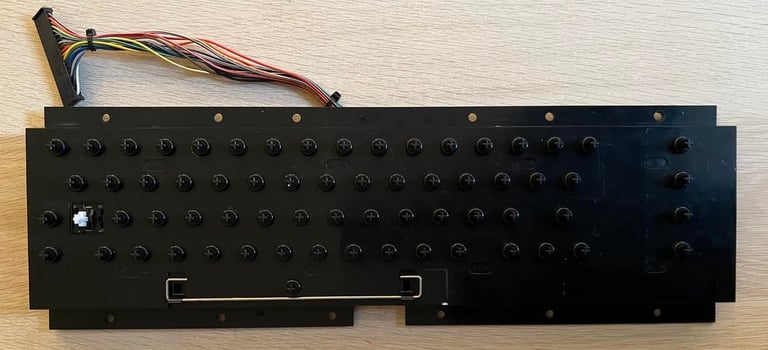
When all the keys are removed the PCB is removed by unscrewing all the screws (about a million) on the back of the keyboard. Note that to get the shift-lock out of the chassis you need to desolder the two wires and then push (forward) to snap it out.
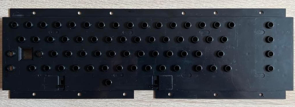
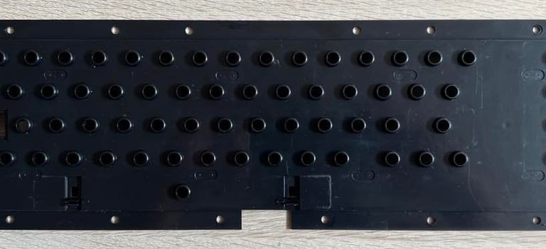
The plastic part is cleaned with mild soap water, and the springs are put in vinegar for a few hours. Quick note: the spring for the spacebar is different from the rest of the keys. So it´s good practice to place this spring in a separate plastic bag when doing refurbishment.
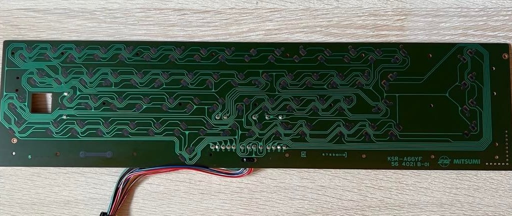
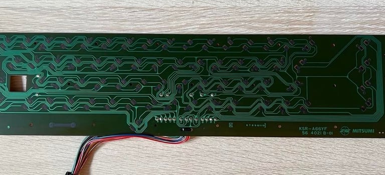
PCB is carefully cleaned with isopropanol on a cotton pad. I stress the word "carefully" - it´s important that all contacts are clean on the PCB but it´s also important not to destroy any of the contacts. They are fragile.
The plungers (the small plastic part connecting the key to the PCB) are NOT cleaned with any water or isopropanol. Instead, I use the method of gently (!) rubbing the rubber part over a sheet of paper. This will loosen, and remove, dust/fat/residue an revive the plunger. At least, that is my experience and I think this way works better than washing them.
Below is a picture of the plastic chassis, the PCB and the plungers assembled after cleaning. Click to enlarge.
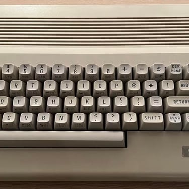
After retrobrighting the keys I notice that not all the keys have the same degree of whitening/yellowing unfortunately. It´s not a very big deal I think, but the optimal result would be if all the keys had the same degree of yellowing. Nevertheless, the end result of the keyboard refurbishing is shown below - I´m quite satisfied with the result. It is also a good idea to bring the keyboard out in the sun every summer. Just normal sunlight (outside) will slowly retrobright the keys.
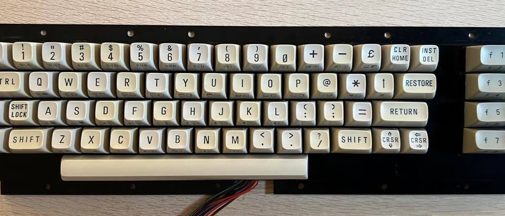
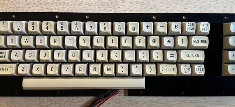
I give the keys another round of retrobrighting. I use 12 % hydroperoxide cream on each of the keys and expose the keys to UV light for approximately 12 hours (the keys are "painted" with cream about every hour). The keyboard is still not completely even, but maybe it got a bit better? The lighting is not identical on the two pictures so it´s not easy to compare. See picture below.

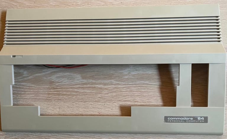
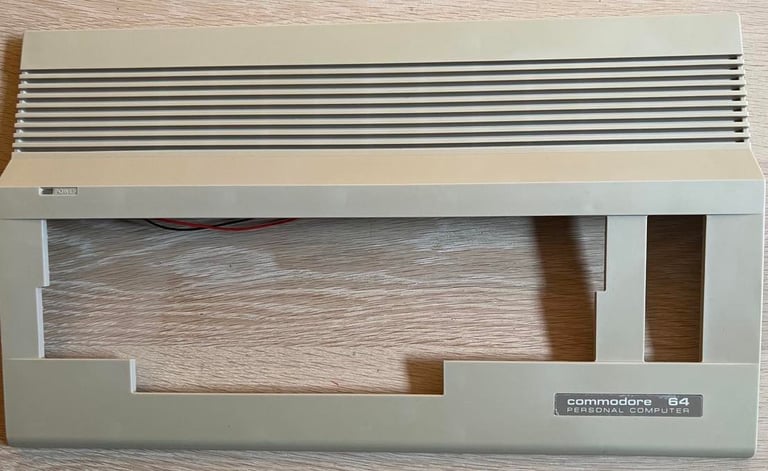
Chassis
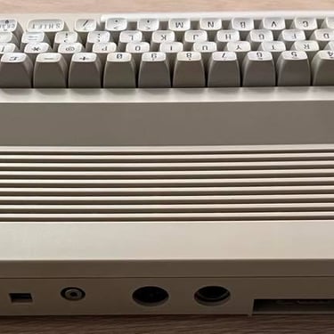
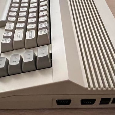
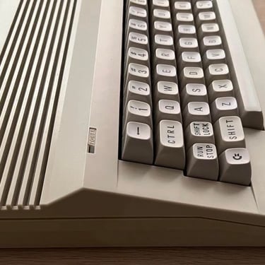
The chassis is split into the top cover and bottom cover part. All parts looks to be intact without any broken parts or deviations. Both the top- and bottom cover are cleaned with mild soap water, and grease stains are removed with a combination of baking soda and isopropanol.
During the summer of 2022 the chassis was also retrobrighted using 12 % hydrogenperoxide cream. The chassis was exposed to direct UV sunlight both under retrobrighting, but also without hydroperoxide cream (sunbrighting).
Also, I believe the plastic film is still present on both the C64 badge and the serial sticker! I´m not 100 % sure, but if you check the pictures below you can judge for yourself. I leave it to the next owner to decide wether to remove the plastic or not...
I´m quite satisfied with the end result of the cleaning and retrobrighting of chassis. See pictures below (click to enlarge).

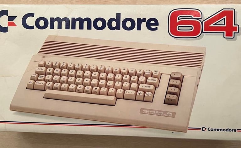
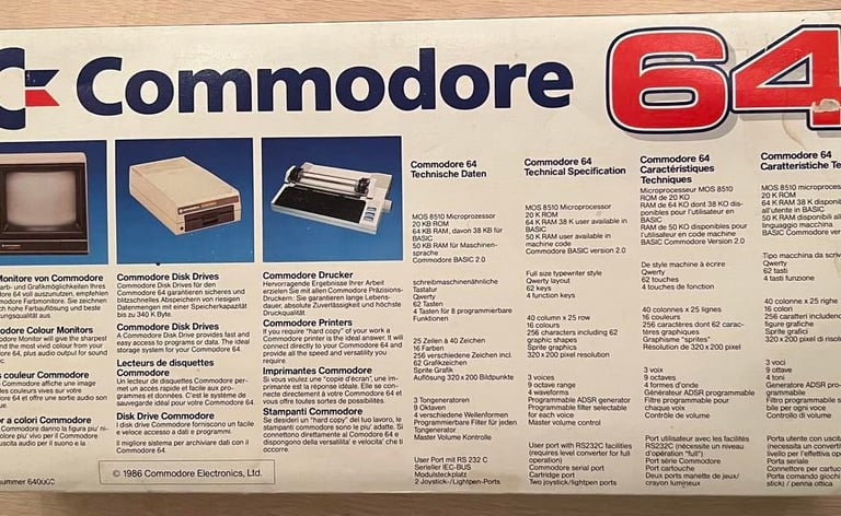
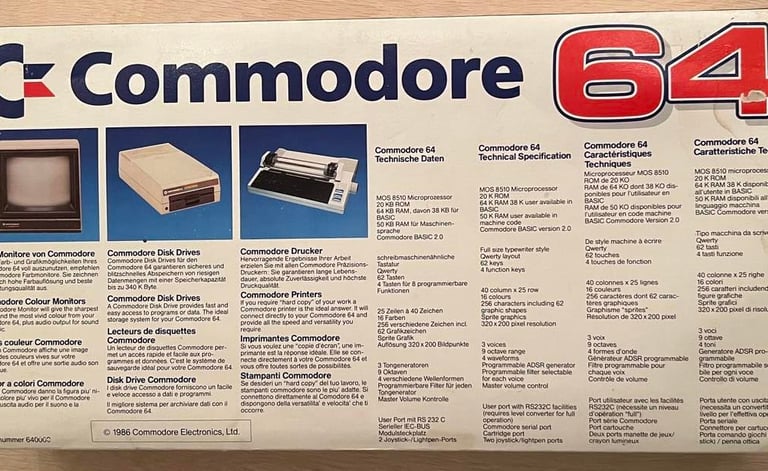
This Commodore 64 come with a quite nice box! Often, the packaging is often quite destroyed, but this C64C have a cardboard box which is quite well preserved! See pictures below.

Main board
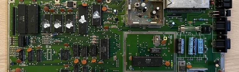
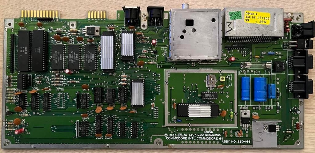
This is the amazing assy 250466 main board in my personal opinion. It was the last version of the longboard from Commodore, and it contains (probably) the best version of the 6581 SID (the R4AR - advanced resonance) and the highly acclaimed R5 version of the VIC-II giving good picture quality. Now, it still need to be verified that they actually are in there, and that they work! People have done some many strange things with their Commodore that nothing surprise me any more...
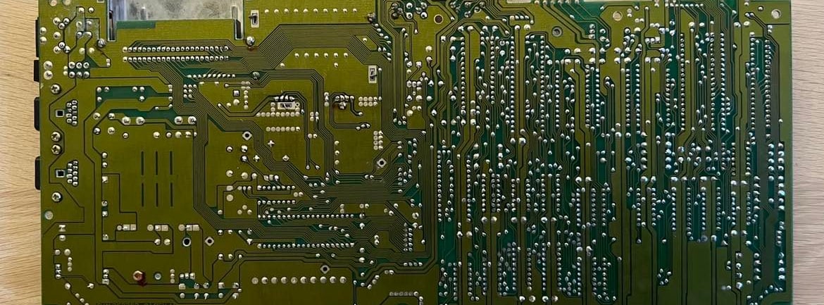
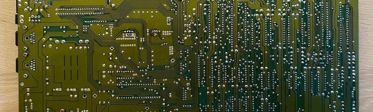
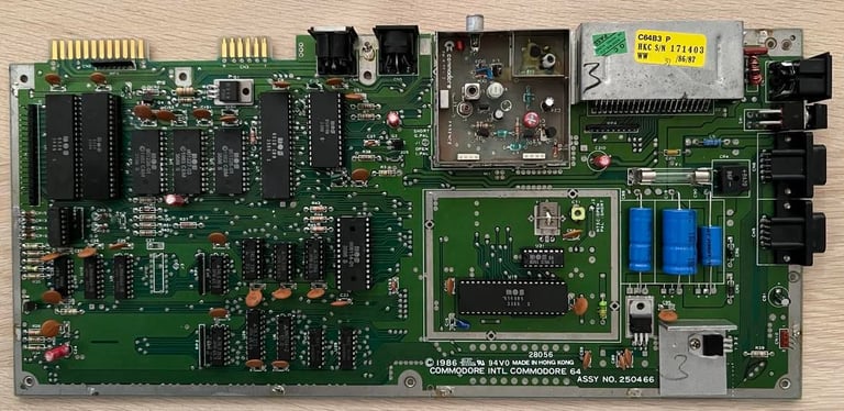
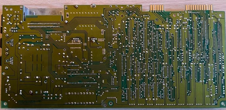
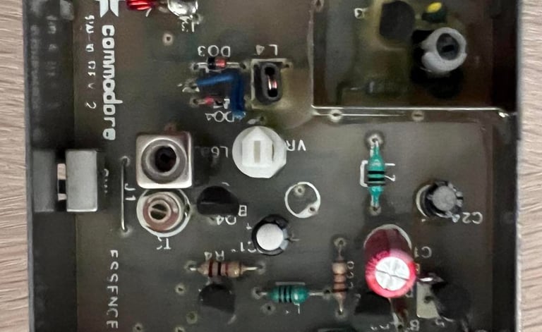
Below you find pictures of the front- and back of the main board PCB before inspection and checking.
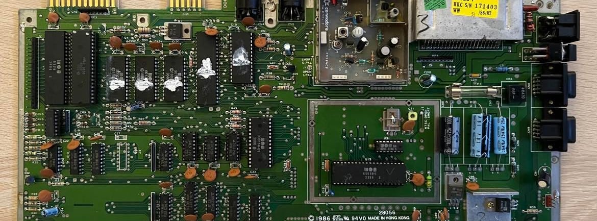
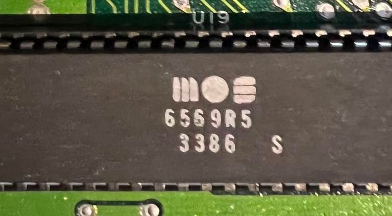
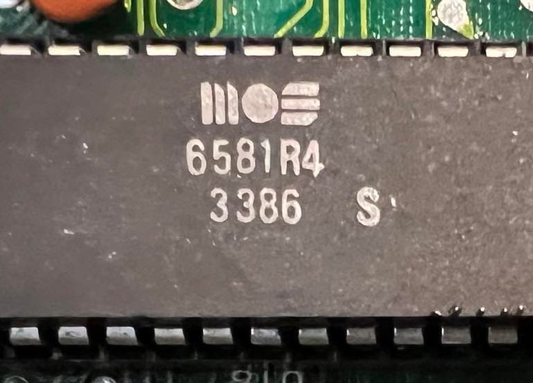
The first I check is the VICII chip version. And, yes, this is the "correct" version the MOS 6569R5! And the SID is version 6581R4! But, what happened to the "AR" postfix? Is this not the acclaimed SID? Well, yes, it turns out to be the same! According to https://en.wikipedia.org/wiki/MOS_Technology_6581#Revisions the SID labeled "R4AR" is just "Minor adjustment to the silicon grade, no die change from R4". So they are identical except for the silicon grade! Nice! See pictures below for these two chips! Take good care of them! They are probably more valuable than gold...(!)
Oh my...! Now I realize that I´ve actually repaired this main board previously! And also used some chips for testing other C64s. If you take a closer look at the first picture of this article (with the main board) and check out the CIA#2. There are two things which gave me this hint; the chip is up-side down (!) and the fabrication date is week 31 of year 1991. But no worries, the machine have not been turned on with the chip in the wrong position. It´s just med who have replaced it the wrong way after I´ve used it for testing in another machine.
The rest of the chips are from mid 1986. E.g. you can see the SID and VIC chip are from week 33 in 1986.
I now remember that this was a classic "black screen" machine. The CIA #2 chip was bad, and that also the 7406 chip was bad. While repairing this machine the following chips were socketed (but only the two were bad):
PLA (MOS 906114-01)
Glue logic chips: 7406, 74LS139, 74LS08 and 74LS258
CIA#2 (MOS 6526)
Both the 7406 and MOS 6526 replacement chips were bought from https://www.retroleum.co.uk/
Anyway, even if this have been repaired by me already (oh my...) it haven´t been really checked and tested. So let´s start with checking the voltages! Both for making sure that all chips get the right voltage and for reference (before and after recap).
There are four voltages I always check:
5 V DC on user port (from PSU)
9 V AC on user port (from PSU)
5 V DC from 7805 voltage regulator (for VIC-II)
12 V DC from 7812 voltage regulator (for SID and VIC-II)
See table below for results.
All electrolytic capacitors are replaced with new quality capacitors. Why? Well, these capacitors are almost 40 years old and they will dry up due to old age. The result of this process is that they will change their capacitance (that is the uF value). This doesn´t necessarily mean that the C64 does not work! But you can experience "odd" behavior of the machine. After all, there is a reason why a specific capacitance was chosen in the first place. I use quality capacitors from Wurth Electronics, Kemet and Panasonic/Vishay.


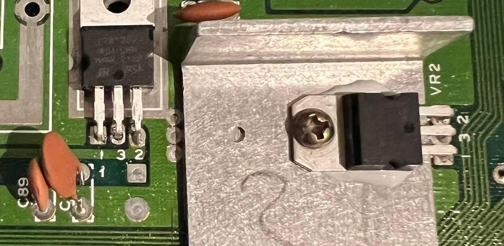
Next step is replacing the 5 V and 12 V voltage regulator. Why? Well, the MOS SID and VIC-II chip are likely to be damaged by too high voltages. And when speaking of "high" voltages we are talking small deviations from 5 V and 12 V. A well known fact is that the 7805 5 V voltage regulator in the original Commodore PSU is likely to fail and damage custom chips. But the same applies for the 7805 and 7812 voltage regulators on the main board. These are OLD, and heat and aging are not a good combination. Therefore I will replace these with new ones. Note that it´s only the 5 V (7805) regulator which is mounted on a heat sink. See picture below (click to enlarge) for the new voltage regulators. The white stuff below the 7805 is only some heat transfer paste.

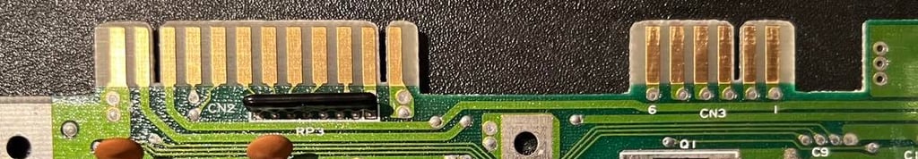
To make sure that the datasette and peripherals such as modems are able to operate without issues it´s important that the contacts where such devices are connected are free from grease and dust. Therefor the user port and the datasette port on the main board is cleaned and checked properly. This is done by using a rubber eraser (GENTLY!) first to remove most of the grease/residue/oxidation and then use a Q-tip with isopropanol. The ports on this C64C looks good after this cleaning. See picture below.

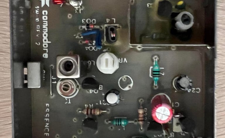
RF modulator
Inside the RF-modulator there are three electrolytic capacitors; 330uF, 100uF and 10uF. As for the main board these capacitors can (or will) loose their capacitance due to aging. But to change these capacitors the whole RF-modulator chassis needs to be removed from the main board. Removing the RF-modulator is (at least in my opinion) not trivial. If you are not careful in this operation you risk lifting pads / traces either on the RF-modulator PCB or on the main board. When removing the RF-modulator I use both the soldering iron, the desoldering gun and the hot air gun.
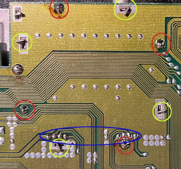
To remove the RF-modulator I do this following these steps (picture below for positions):
With a needle nose plier I align the four metal clips to be parallell with the holes (yellow circle)
Using both the soldering iron and the desoldering gun I remove the solder from the four pins (red circles). I use both to get enough heat to really melt the solder - and when everything is completely melted I engage the vacuum to suck it.
Adding fresh solder to the eight pins connecting the main board to the RF-modulator (blue circle) first. Then using the desoldering gun to remove the solder.
I find a small glitch between the main board and the RF-modulator and carefully pry a small flat screwdriver in. Then I use hot air around the pins until the RF-modulator starts to come off. This sometimes takes some time so it´s important to be patient.
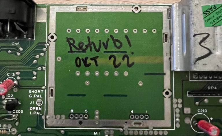

Below is a picture of the main board with the RF-modulator removed. No traces lifted!

I use only quality electrolytic capacitors for replacement. RF-modulator with the new caps installed:
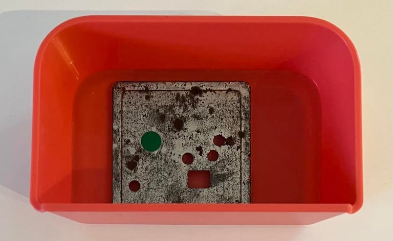
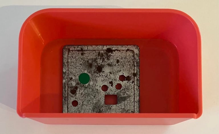
The metal lid of the RF-modulator is quite rusty (?) or have some kind of corrosion. This is only "cosmetic", but I try to remove some of the corrosion by soaking the RF-shield in vinager for 24 h. Let´s see if it has any effect!
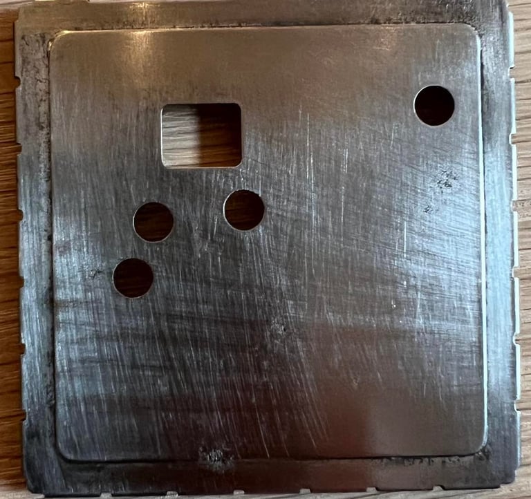
After being soaked in vinegar I polish the metal with some P180 sanding paper. And the result is quite good!

Heat sinks
Heat sinks are added to the CPU, SID, PLA and VIC. Is this strictly required? Well, probably not but I do believe that excessive heat can decrease the life of a chip. Therefore I add the heat sinks to these chips as a preventive measure. Below are a picture where the heat sinks are added to these custom MOS chips.

Testing
Moment of truth. Does it work? I do think so, but the only way to be sure is to test it properly. The testing is separated in two parts:
Testing of the basic functions and chips: VIC-II, SID, PLA, CIA, CPU and keyboard
Testing of normal operation such as playing games, demos, joysticks and loading of software by datasette and floppy
Basic testing
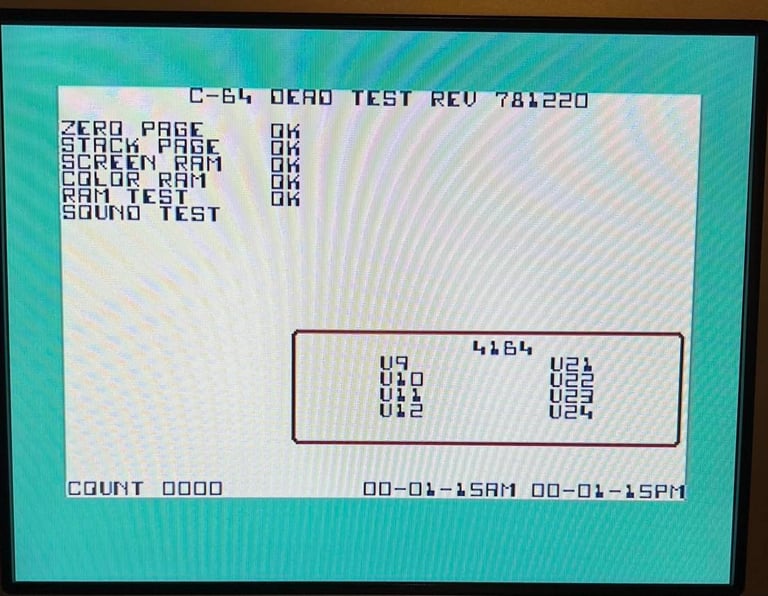
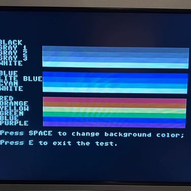
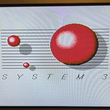
The first test is to run the Dead Test cartridge. This is a very basic test checking the CPU, Color RAM and 64k RAM, SID, PLA, CIA and VIC chip. The dead test will not use the Kernal, BASIC og character ROM so these are not checked here. Nevertheless, the Dead Test pass with flying colors.
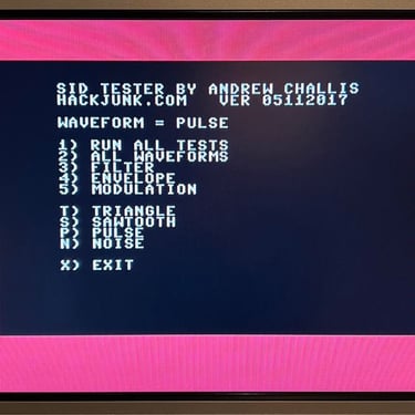
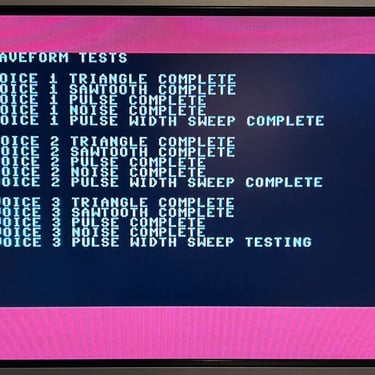
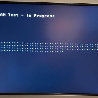
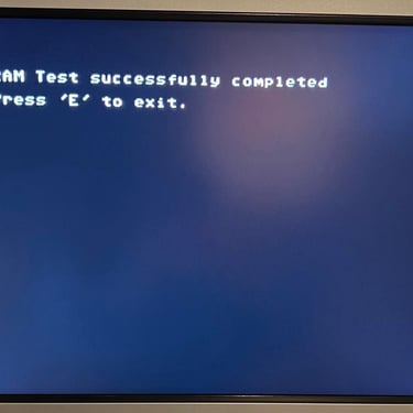
Next up is the SID, RAM and the VIC. To do this I use the Commodore SID tester and Doctor64 (see My Tools page) respectively. All test test pass without any problems.
Testing normal operation
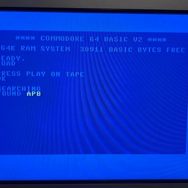
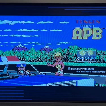
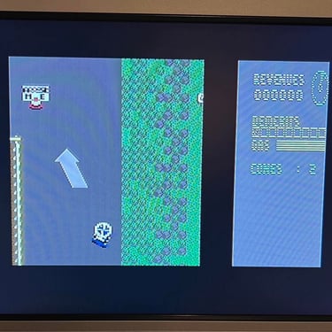
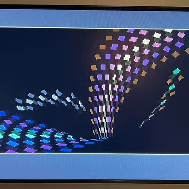
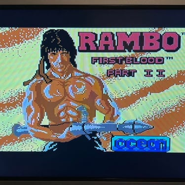
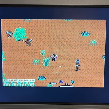
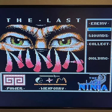
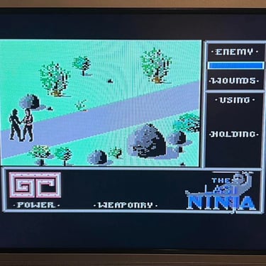
Knowing that the basic functions are working as expected the next step is to test the C64C in normal working conditions. That is testing the machine playing games, watching demos and such while checking that video looks ok, sound works as expected and that reading from cartridge/floppy/datasette etc. works as it should. I use the UltimateII+ cartridge for this purpose. This cartridge is a very close approximation to devices such as datasette/floppy and rule out any issues with the media itself.
Last part of the basic testing is to verify that the keyboard works - that all keys are operational and responsive. This test pass without any problems.
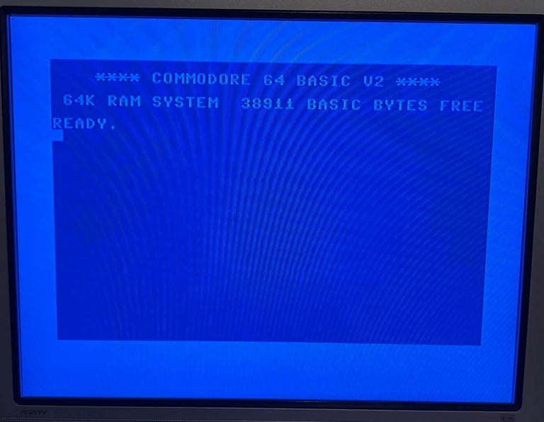
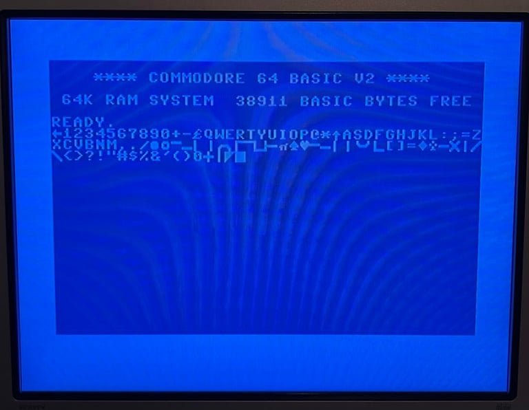
Then the classic blue Commodore is checked. All 38911 kB of BASIC RAM are available.

Final result
"A picture worth a thousand words"
Below is a collection of the final result from the refurbishment of this C64C. Hope you like it! Click to enlarge!