

C64C [PAL]
Ser. No. 876659
Assy 250469
Artwork 252311 (REV 4)
Starting point
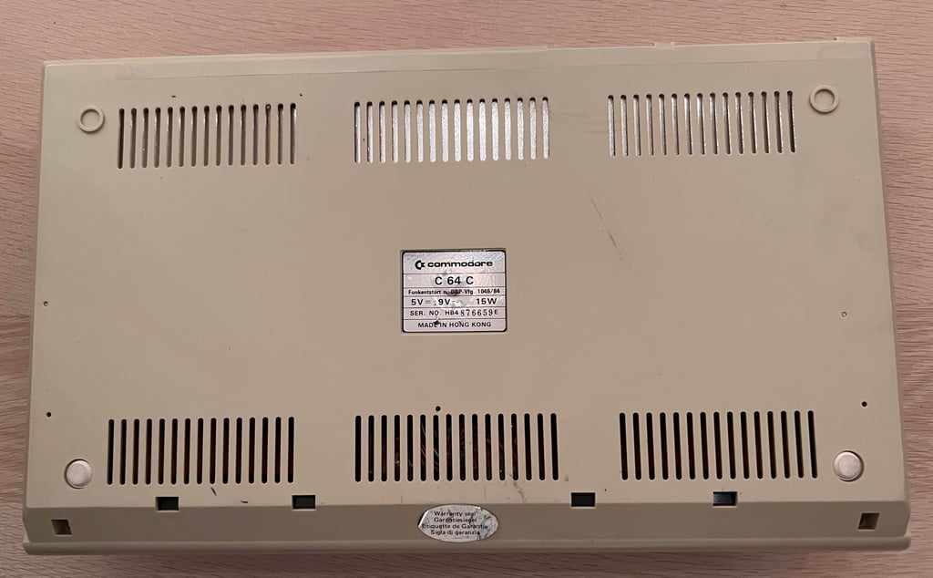
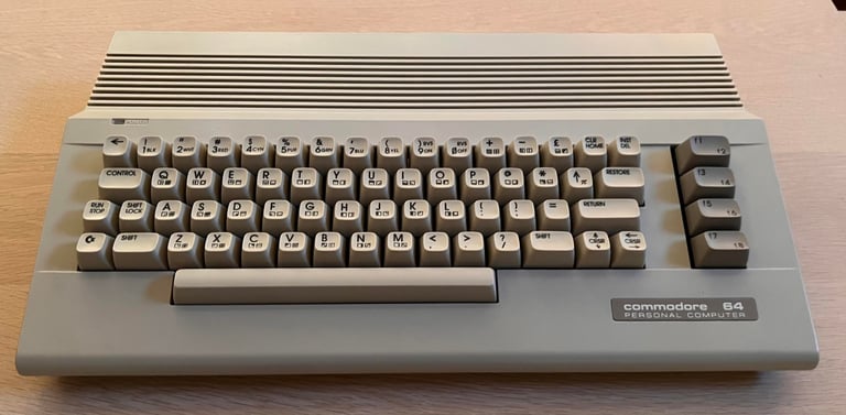
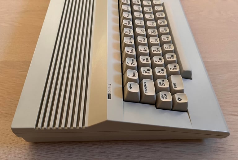
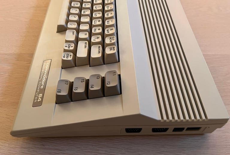
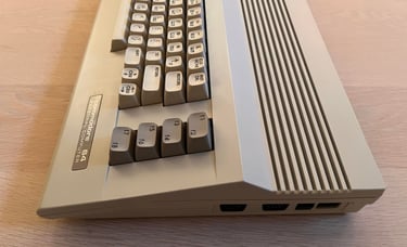
This C64C looks to be in quite good condition before refurbishment. I don´t know if it works or not, but besides from being dirty and full of grease marks I cannot see any severe damage to it. There are some dark marks on some of the keyboards. The Commodore metal badge is partly bent, but nothing I can´t repair, I guess. It is quite yellowed so some retrobright would be required.
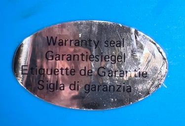
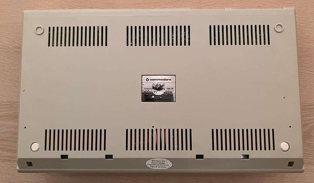
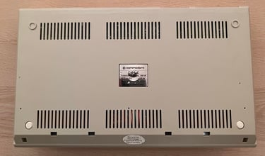
Notice that the warranty sticker is still on. Chances are that I am the first to open this machine in over 30 years (!). Looking for a fine refurbishment here!
UPDATE: For some odd reason five of the pictures below have gone missing (!). Only the picture of the bottom case remain. Sorry for the inconvience!
Refurbishment plan
To refurbish this C64C the plan is to do this trough the following steps (some of them in parallell):
Clean and remove stains from the exterior casing
Clean and restore the keyboard
Retrobright casing and keycaps
Refurbish mainboard (cleaning, checking, repairing, replacing capacitors and voltage regulators, adding heat sinks etc.)
Recap RF-modulator
Verify operation by testing
Opens it up...
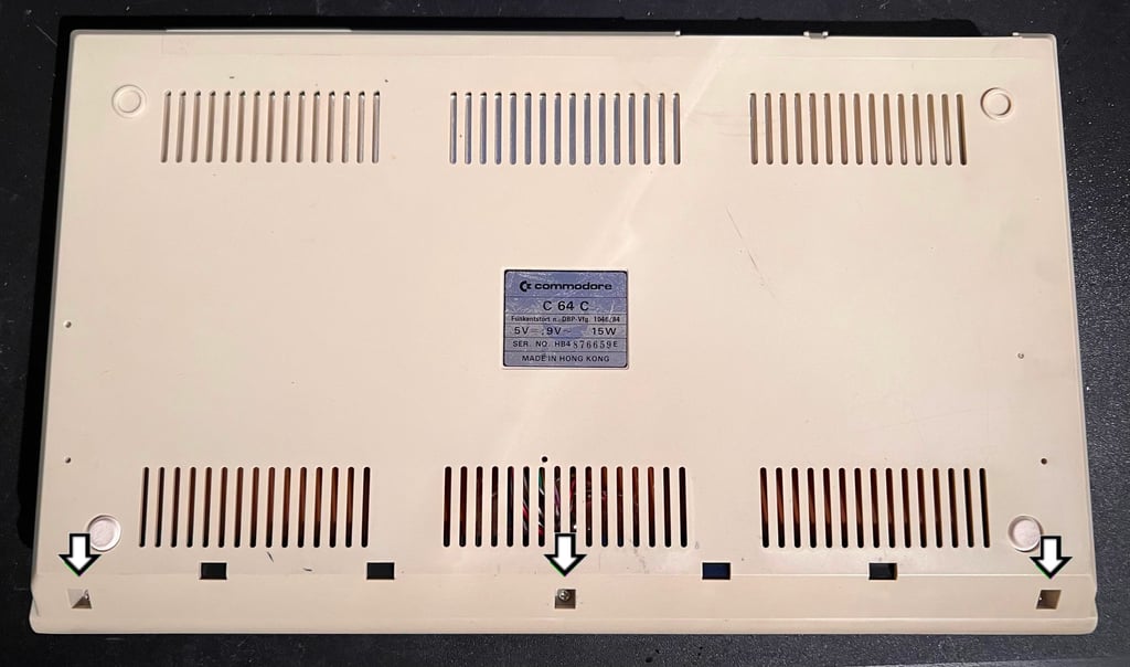
The warranty sticker is carefully removed by using some hot air from a hair dryer while using a pair of tweezers to remove it. Then the three screws (see picture below) are removed to separate the top- and bottom cover.
Removing the warranty seal without damaging it… shows that this sticker is no guarantee that no one has opened it before...

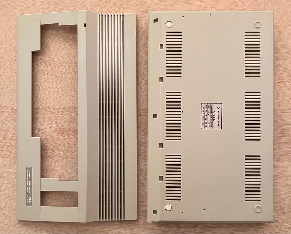
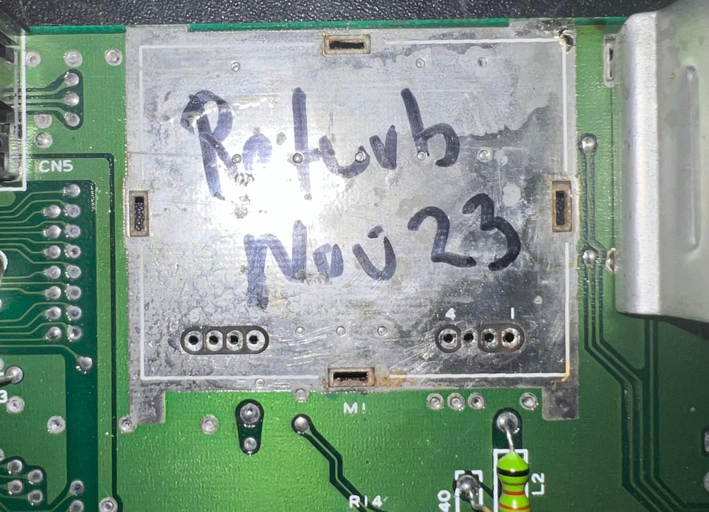
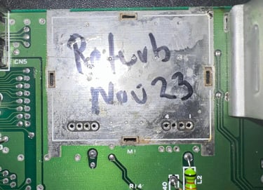
The top cover is lifted from the bottom cover and the inside is revealed. Perhaps for the first time in over 30 years. It looks to be in very good condition. Very little dust, no sign of rust and even the RF-cardboard shield looks pristine.
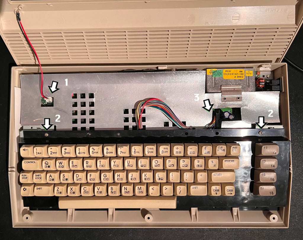
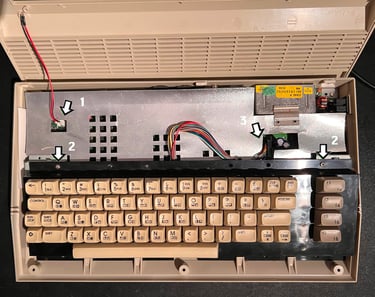
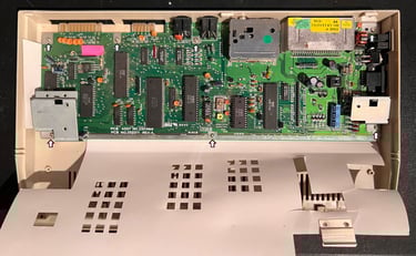
To open it up further the LED is removed first (“1”). Then the two machine screws holding the keyboard are removed (“2”) and finally the keyboard connector is pulled from the mainboard (“3”).
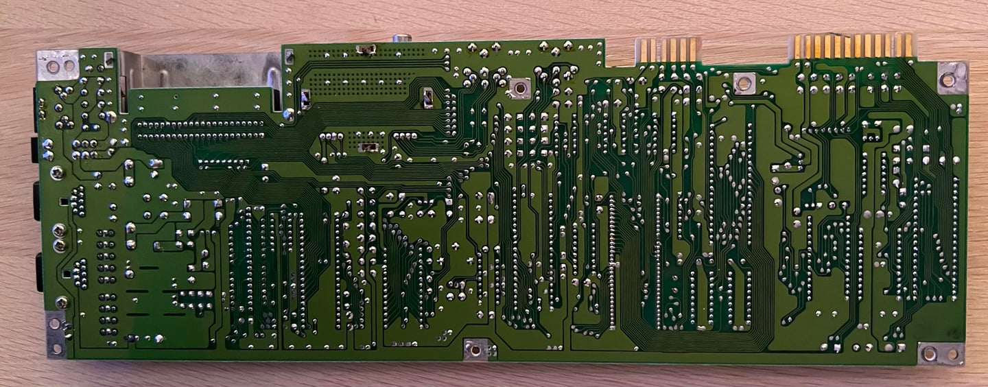
With the keyboard and RF-shield out of the way the mainboard is revealed. It looks very good!
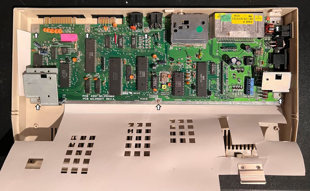
The two screws holding the metal keyboard stand offs are removed, and the remaining five screws are removed from the PCB. This separates the bottom cover from the PCB.
Exterior casing
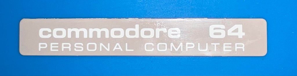
The top and bottom cover is cleaned properly with mild soap water. Most of the dirt and grease come off very easy, but some of the stains needs to be handled with isopropanol. As seen in the previous chapter the “Commodore 64” badge is partly loose and bent. The badge is removed by adding some hot air with a hair dryer, while at the same time using a sharp knife to peel the badge off.
After removing the badge it is straightened as good as possible. The result is quite promising. See picture below.

Top- and bottom cover is quite yellowed so it is retrobrighted using hydro peroxide cream. The cream is applied frequently every hour for about 10 hours while the covers are wrapped in plastic film and exposed with UV light.
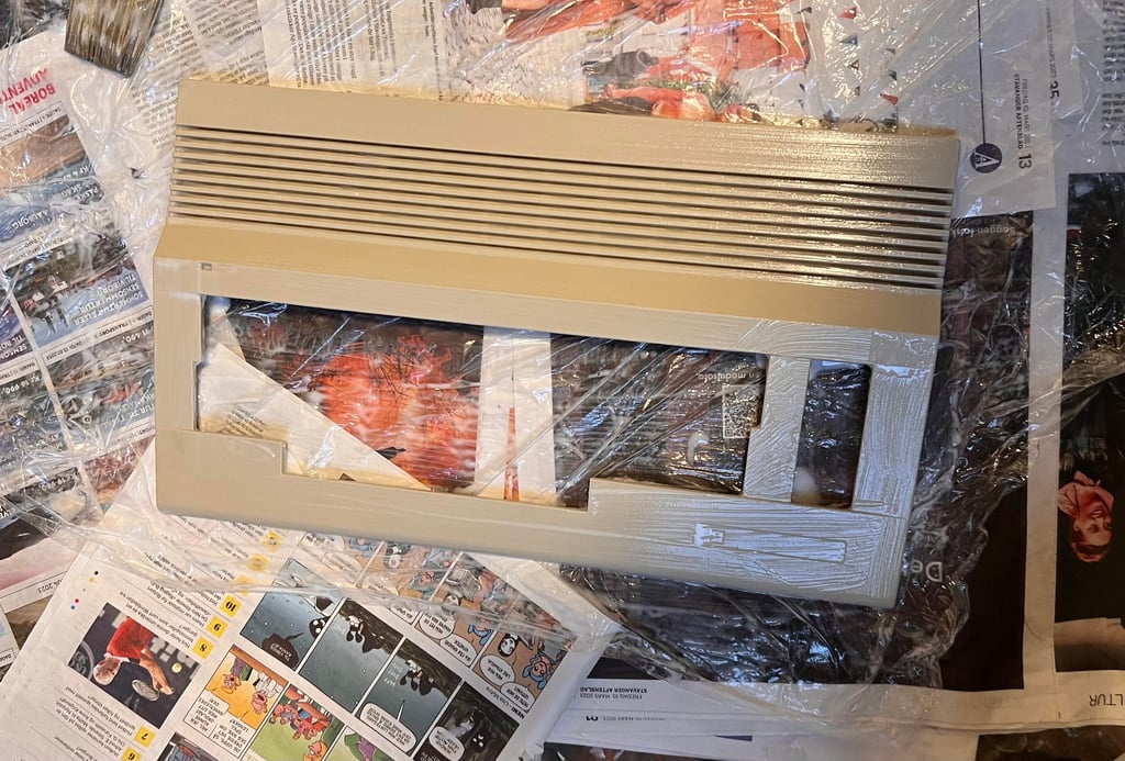
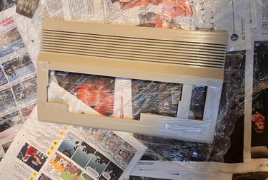
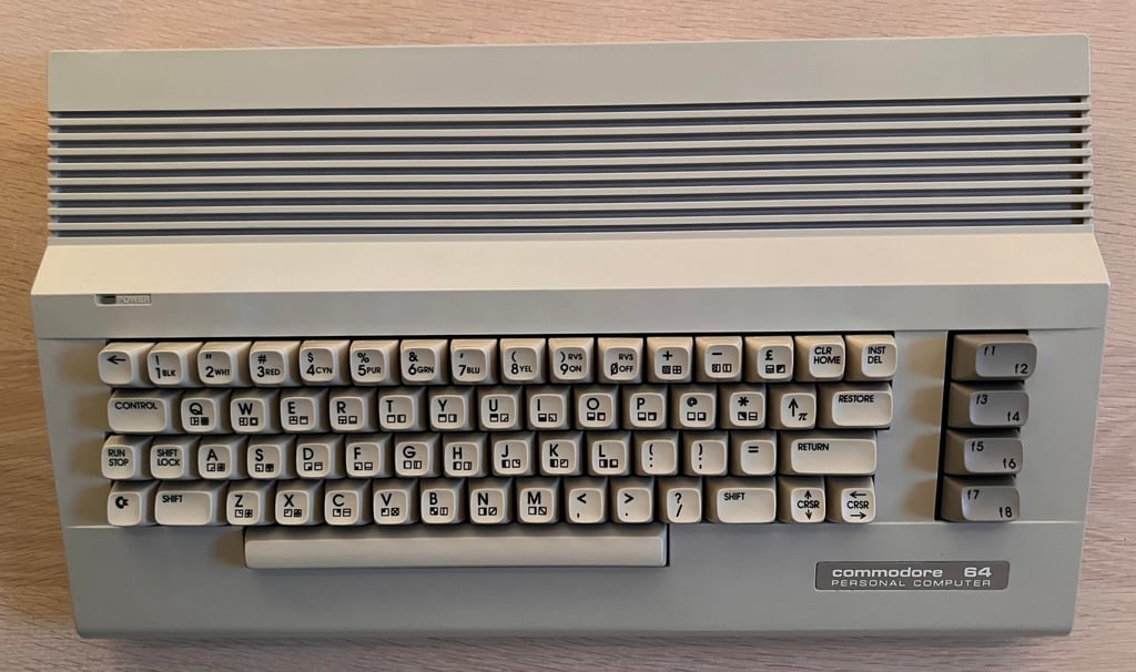
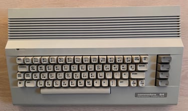
The result after the retrobright is very good. As can be seen from the picture below most of the yellowing is gone.
Keyboard
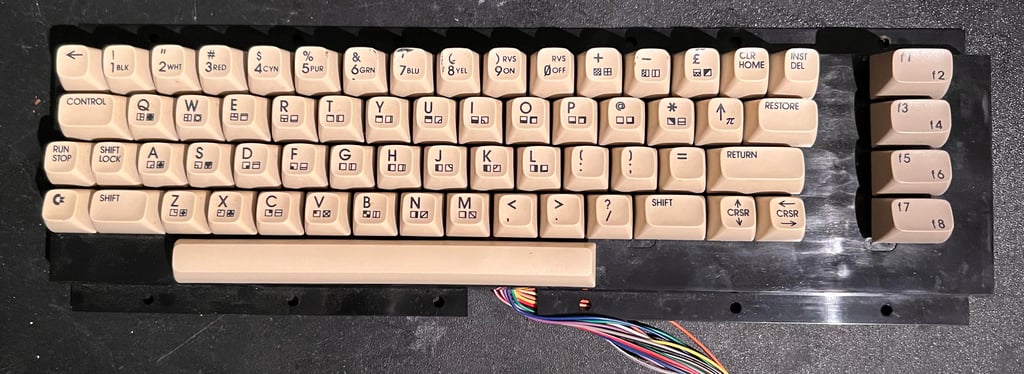
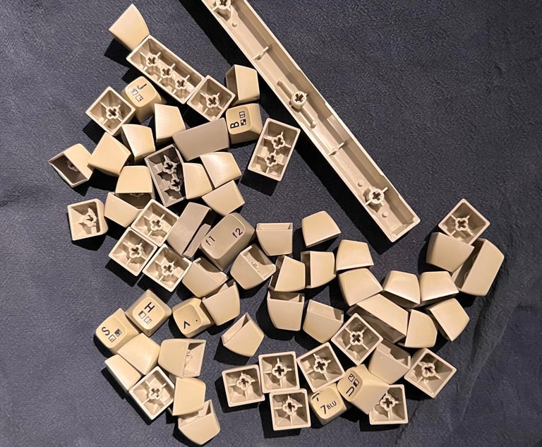
The keyboard appears to be in ok condition. It is dirty and a bit yellowed, but looks otherwise to be ok. There are some marks on the top row of keys (see “5”, “6”, “7” and “8”) which I hope can be removed with some isopropanol.
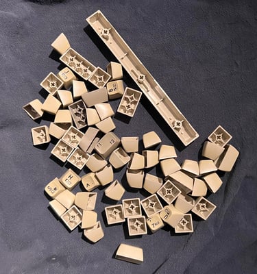
Each of the keycaps are removed carefully with a keycap puller. I recommend using this kind of tool to avoid that the plunger beneath the keycap breaks. Note that there is a small spring under each keycap, and that the spring under the spacebar is larger then the rest – so it is good practice to keep this in a separate bag.
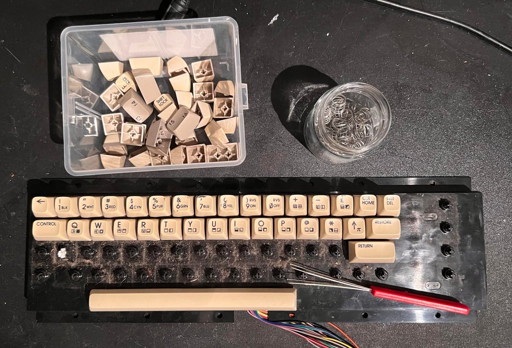
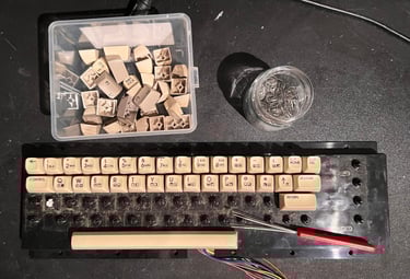
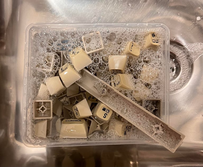
The keycaps are quite dirty. So they are placed in a box of mild soap water for about 24 hours. Then they are left to dry. Some of the keycaps needs to be cleaned with some isopropanol to get rid of all the marks.
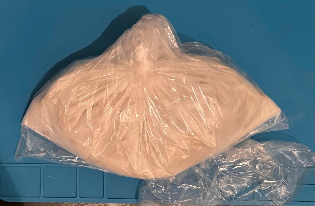
There is a bit of yellowing on the keycaps so some retrobright would help. Therefore all the keycaps are placed in a plastic bag filled with hydroperoxide cream for about a week. During this week the bag is “massaged” and placed in a UV chamber for about 10 hours.

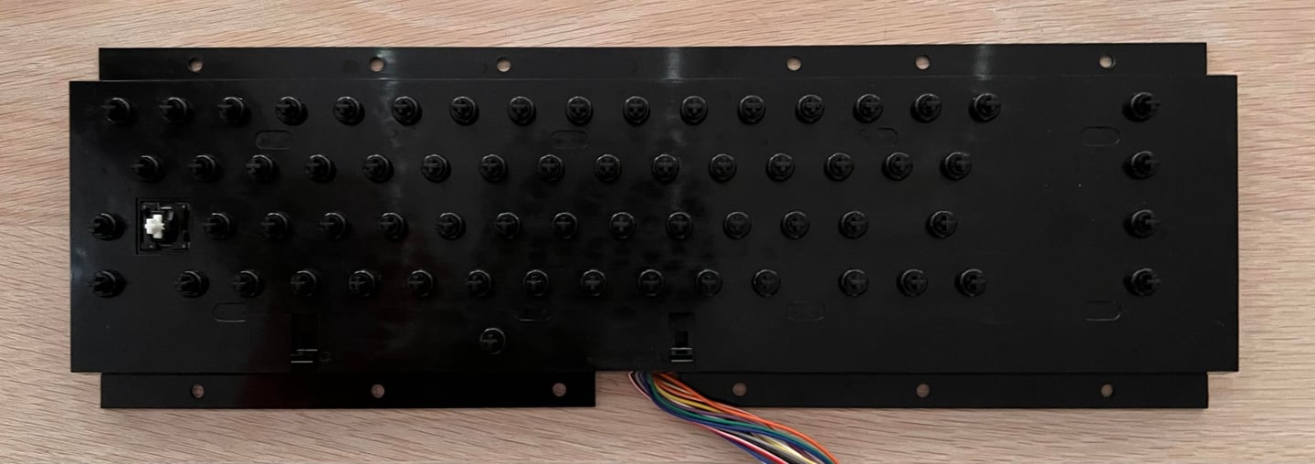
Before the 23 small screws are removed wires connecting the SHIFT LOCK key are desoldered (see arrows). To remove the SHIFT LOCK key gently push the key from the backside of the keyboard towards the front until it pops out.
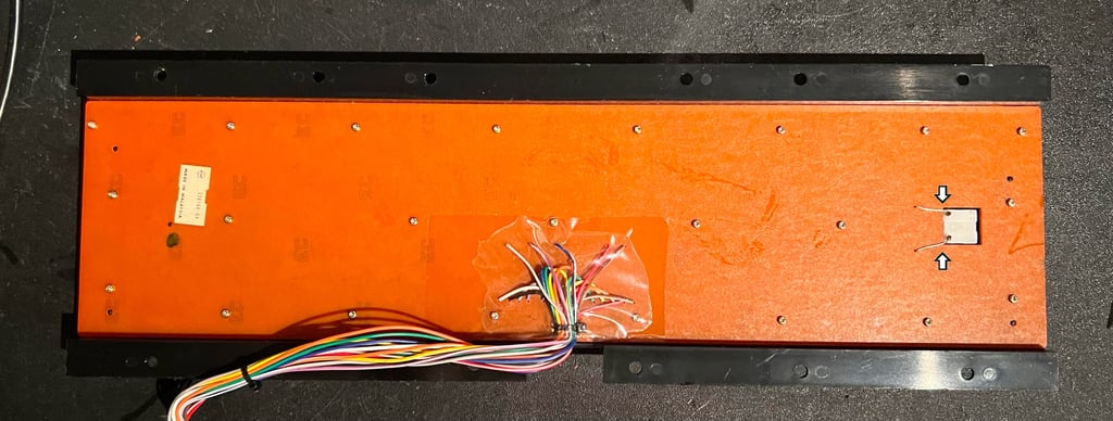
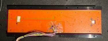

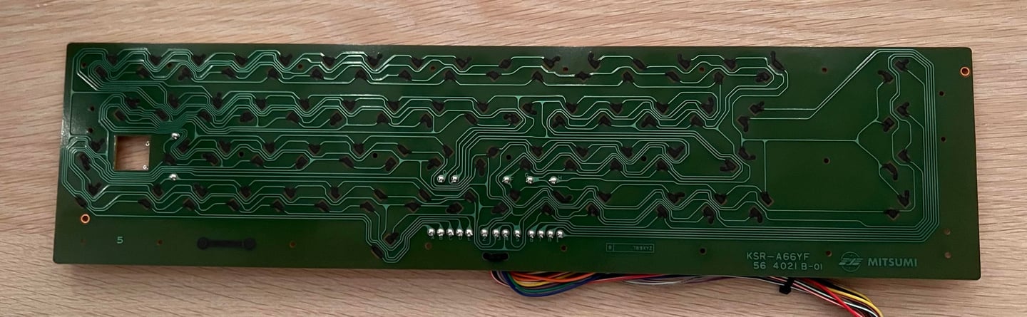
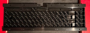
This is a Mitsumi KSR-A66Y keyboard which is common in these C64 breadbins. Note that this PCB has carbon pads so extra care is required when cleaning. Some distilled water on a fine cloth is used to remove the dirt and grease. Below is a picture of the keyboard PCB after cleaning.
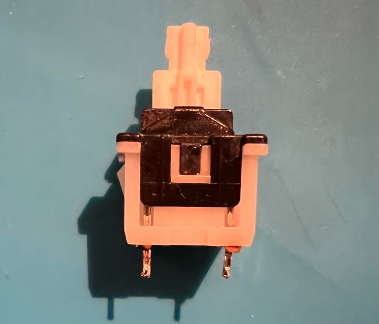
All the plungers are removed and the plastic casing is cleaned with some mild soap water. After drying the casing the plungers are put back in. Each plunger is wiped carefullt with some isopropanol on a Q-tip.

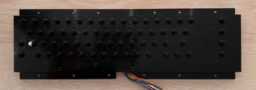
The PCB and SHIFT LOCK is mounted back in the plastic casing. It looks good as new!
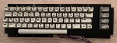
All keycaps looks very good after retrobrighting. I am quite pleased with the result. Below is a picture of the keyboard completely re-assembled.

Mainboard
This is an Assy 250469/Artwork 252311 (Rev 4) mainboard from Commodore. These mainboards are often classified as “shortboards” compared to the “longboard” found in older Commodore 64 breadbins. The main differences:
64 pin Super PLA – Compared to the old 28 pin PLA this Super PLA contains in addition to PLA functionality a lot of the other glue logic.
No 12 V rail used to supply the VIC-II and SID – Compared to the old breadbin which has dedicated 7805 and 7812 voltage regulators to supply additional voltage sources.
MOS 8500 CPU – Compared to the Commodore 64 breadbin which normally use the MOS 6510 CPU (note that these chips are interchangeable so they could be used in both).
MOS 8580 SID -Compared to the breadbin which use the MOS 6581 SID. Note that these are not interchangeable since they use different voltage supplies.
MOS 8565 VIC-II – Compared to the breadbin which use the MOS 6569 VIC-II. Note that these are not interchangeable since they use different voltage supplies.
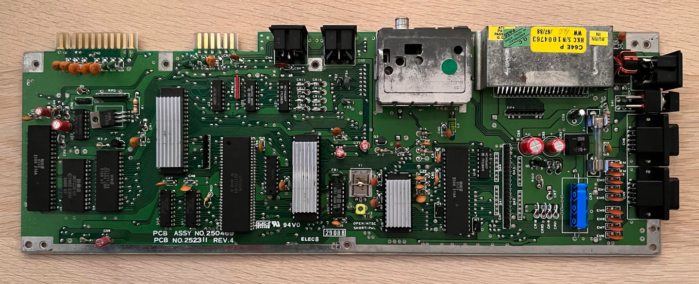
Visual inspection
The mainboard really looks to be unchanged since it was produced. That is quite amazing. I can not see any sign of rework anywhere. So it is very probable that I am the first person to see this mainboard in over 30 years…
There is quite some dirt and grease on the mainboard, but it looks to without any corrosion or other damage. See picture below.
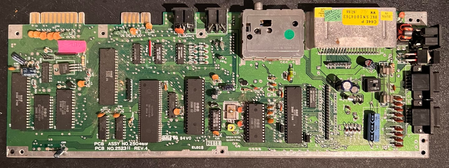

Below is a list of all the main chips on the mainboard:
Initial test
Before power is turned on the user port is checked for any short circuit on the +5 VDC or 9 VAC power rails. For detailed information on where to check please see the article “Checking the C64 voltages”.
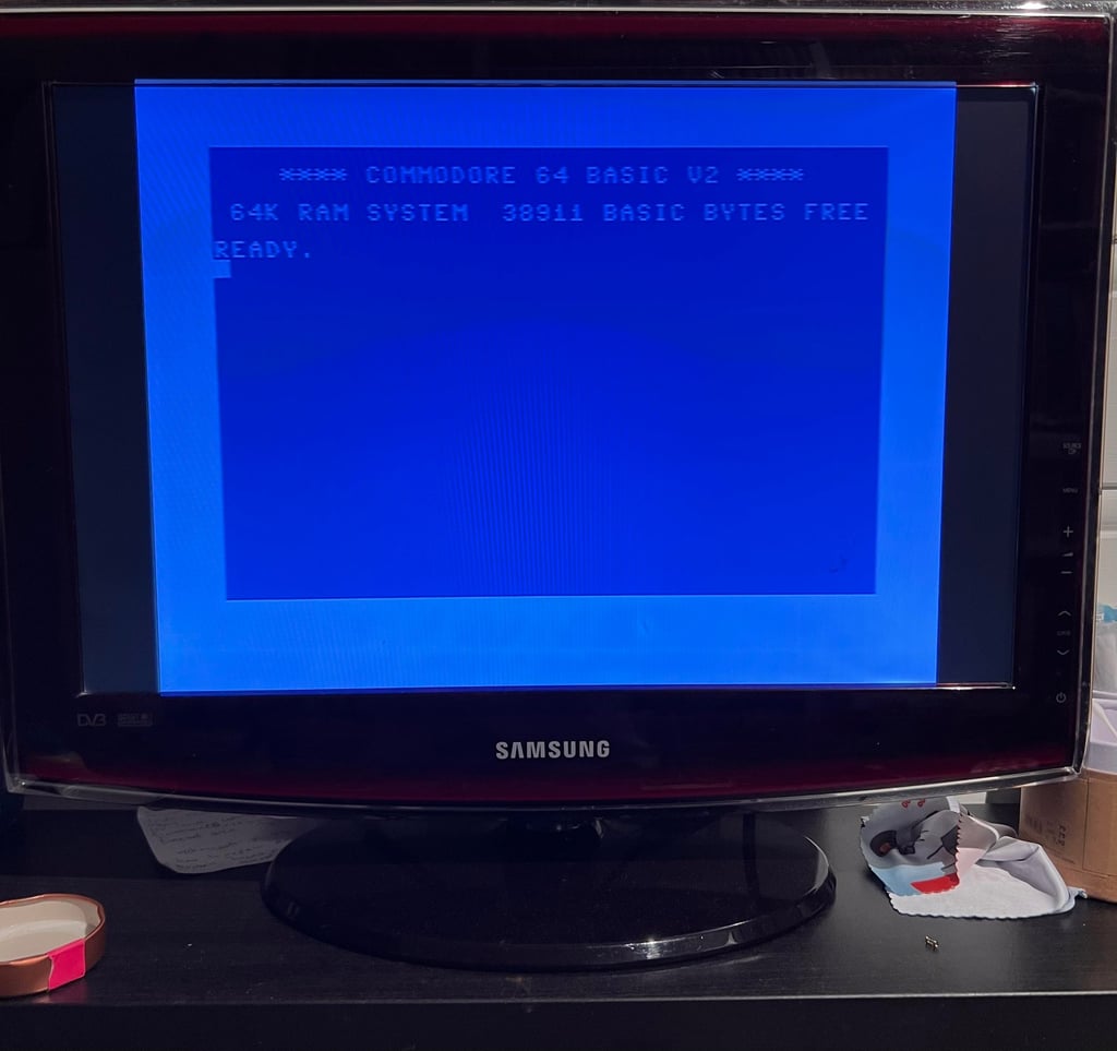
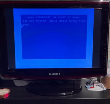
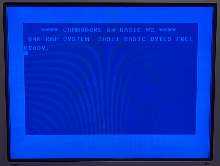
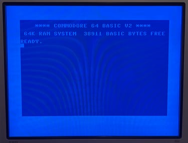
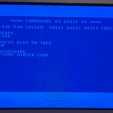
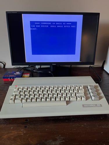
No short circuit is detected so it should be safe to turn on. And what a nice surprise! The good old blue screen with 38911 KB BASIC FREE appear. There could still problems, but this is a good start.
Checking the voltages
A prerequisite for the Commodore 64 to work flawlessly is that all voltages are within acceptable range. Therefore all the relevant voltages are measures according to the HOWTO article “Checking the C64 voltages”. Note that this a C64C and therefore depending on fewer voltages.
The measures voltages are shown in the table below. All voltages are within tolerances. Note that this table will be updated after refurbishment also.
Replacing the electrolytic capacitors – mainboard
This machine is over 35 years old and part of good practice the electrolytic capacitors are replaced. Even though that most of the old capacitors are probably within acceptable tolerances, capacitors will eventually dry up and could case odd behavior.
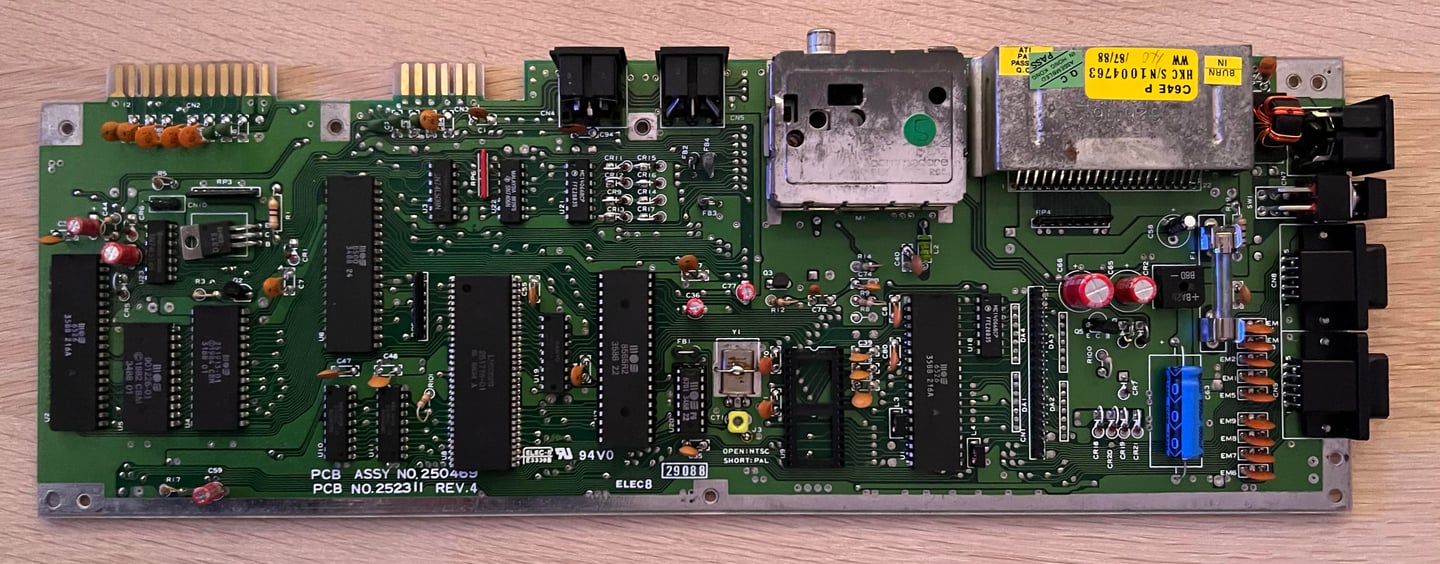
The list of replaced capacitors on the mainboard can be found in the capacitor list. Below is a picture of the mainboard after the capacitors are replaced.


Replacing the electrolytic capacitors – RF modulator
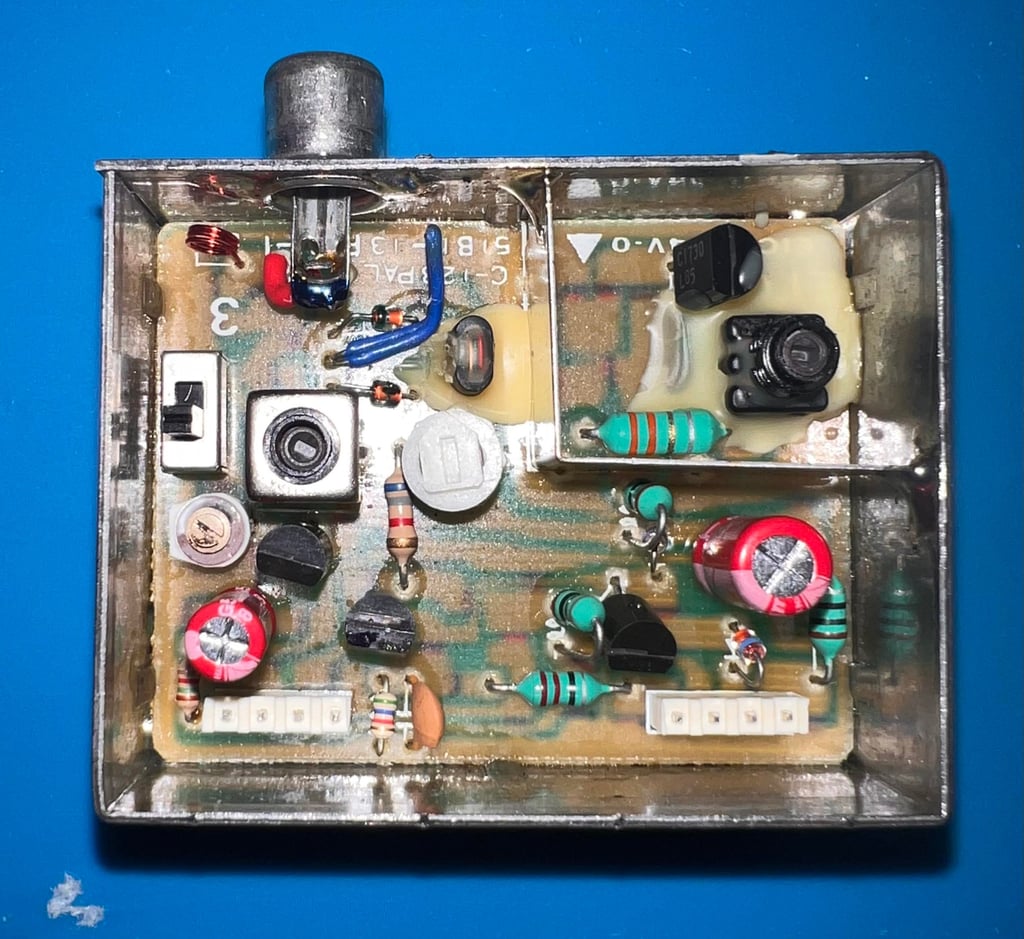
Replacing the electrolytic capacitors inside the RF modulator is straightforward – but to get the RF modulator off the mainboard is not trivial. It is not that it is a complex operation, but it is quite easy to damage traces or pads either on the mainboard or the PCB inside the RF-modulator if you are not careful. In the HOWTO article “desolder the RF-modulator” you can find a description on how I do this using a combination of a desoldering station, soldering iron and hot air.
The RF-modulator is desoldered without any damage to traces or pads. See picture below.
This is a Commodore RF-modulator with P/N 251916-03. There are only two electrolytic capacitors in this modulator according to the capacitor list: 1 x 10 uF [16 V] and
1 x 220 uF [10 V].
Below is a picture of the RF-modulator with the new electrolytic capacitors in place.

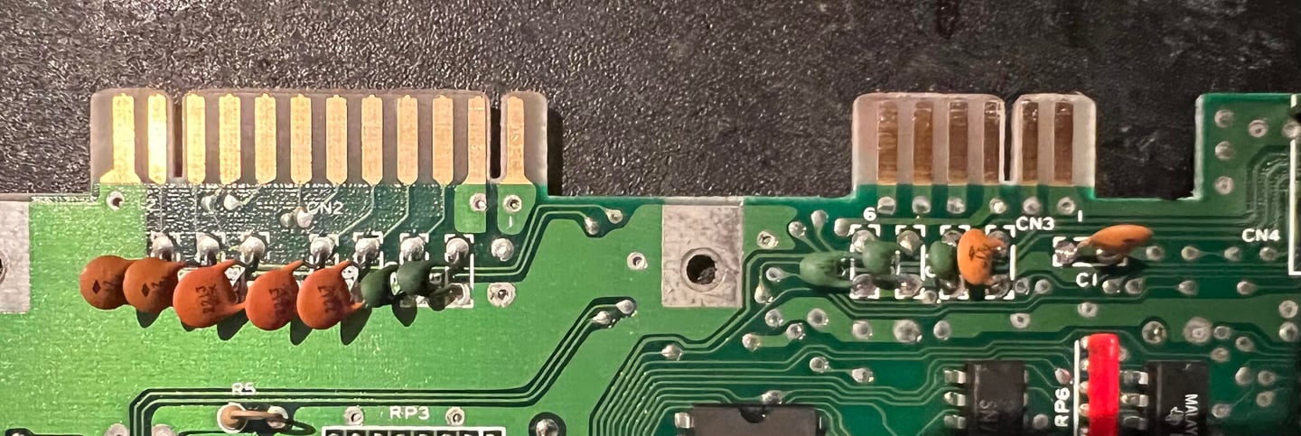
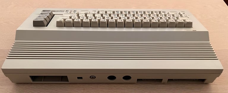
Cleaning the user- and datasette ports
For the connected peripherals to work flawlessly the user- and datasette ports needs to be clean. After 30-40 years these are quite often dirty and oxidized. The way to clean these is to use a normal rubber eraser first on the connector to remove most of the grease. With this operation you will see that the copper will get shiny. Finally the connectors are cleaned thoroughly with isopropanol and a Q-tip. Note that the ports have copper connections on both the top- and bottom side of the mainboard.
Adding heat sinks to custom MOS chips
The Commodore 64C does not run as hot as the breadbin C64. Nevertheless, custom chips such as the CPU, VIC-II and the SID will get quite warm. The heat can increase the probability of the chip failing so it is good practice to use heat sinks to transfer the heat faster to the surroundings. Most of the heat is transferred from the chip legs to the mainboard, but the heat sinks will help to transfer the heat from the top center of the chip to the surrounding air faster.
Below is a picture of the mainboard with heat sinks mounted on the CPU-, VIC-II and SID chip.
Testing
Proof is in the pudding - does it work?
Testing is done through two main stages:
Testing the basic functionality and chips
Testing by using the machine playing demos, games etc. accessed by both floppy and datasette to verify correct operation
Basic functionality and chips
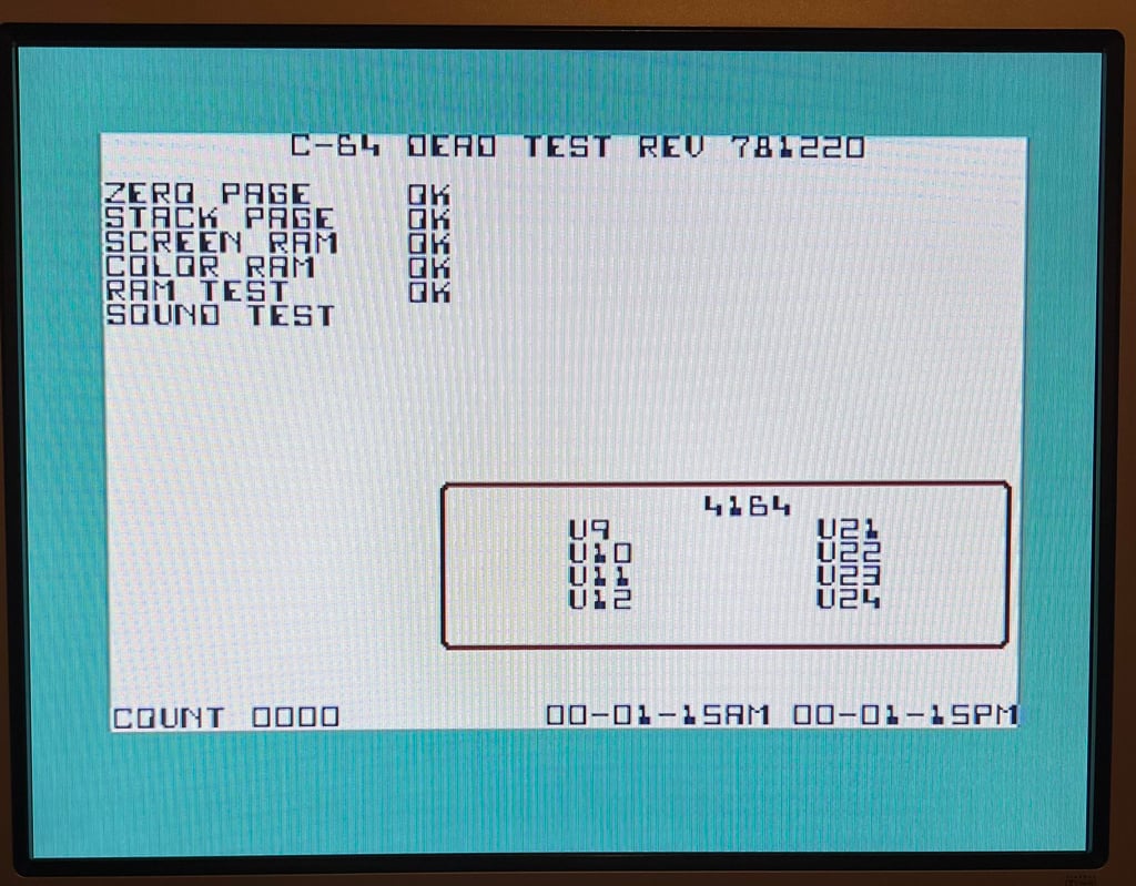
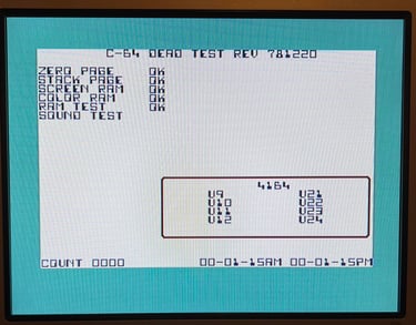
First test is done using the Dead Test Cartridge. This test doesn´t test all the functionality of the Commodore 64, but it does test the basic functionality of the major chips such as the CIA #1/2, CPU, VIC-II, PLA, RAM and SID. As the picture shows below the test is passed.
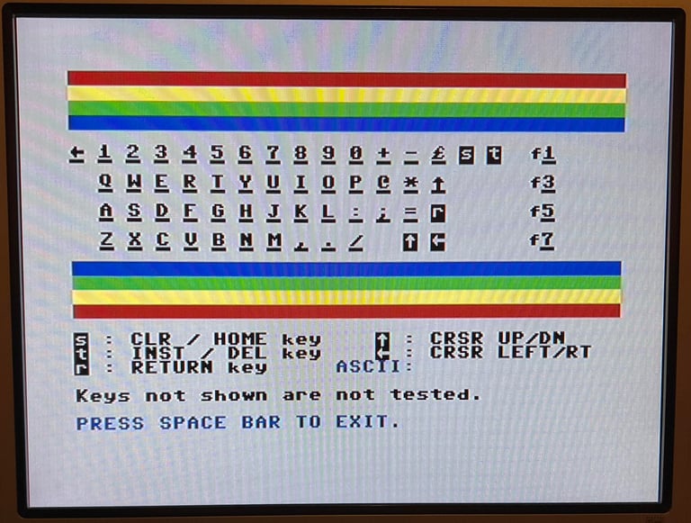
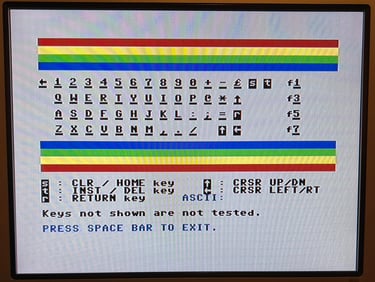
Next test is to power the Commodore 64 to the blue boot up screen and also check the keyboard to make sure all keys works as they should. The test is passed; all keys works and 38911 BASIC Bytes Free.
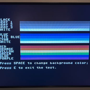
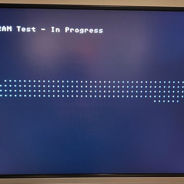
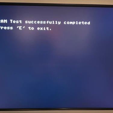
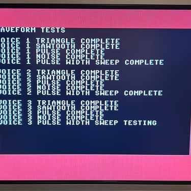
The basic functions of the VIC-II, SID and RAM is tested with 64 Doctor. Note that this is to be considered as basic functionality - more advanced (?) functionality such as sprite handling / collision detection / advanced audio will be tested later. But the basic tests pass without any detected faults (click to enlarge).
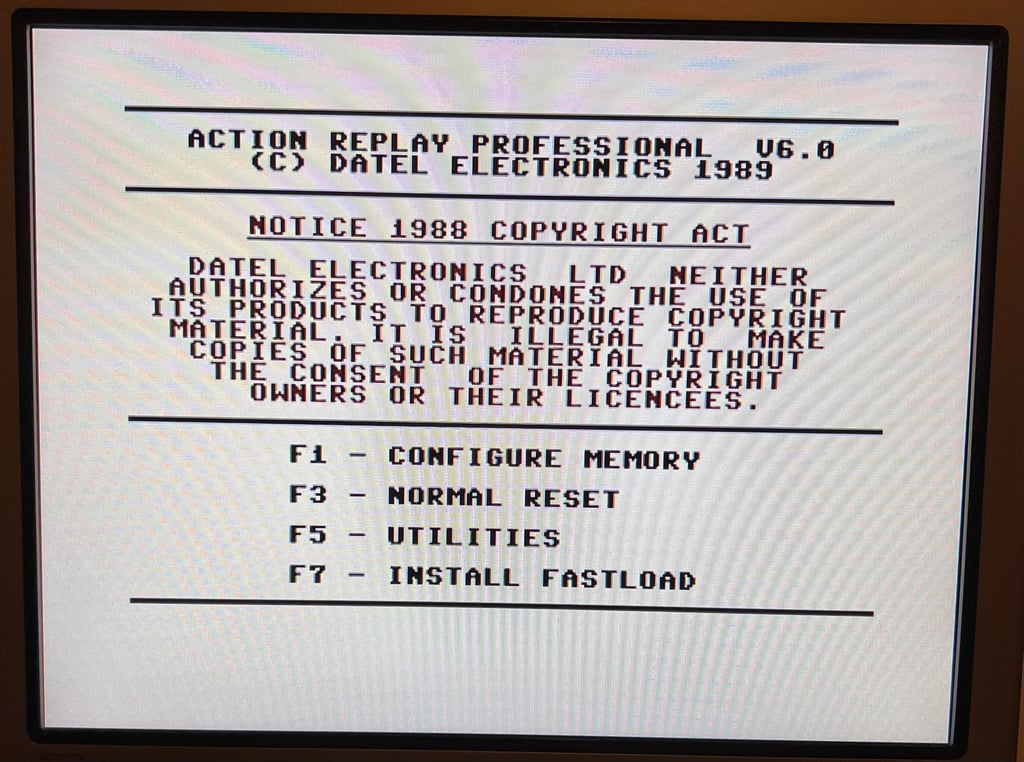
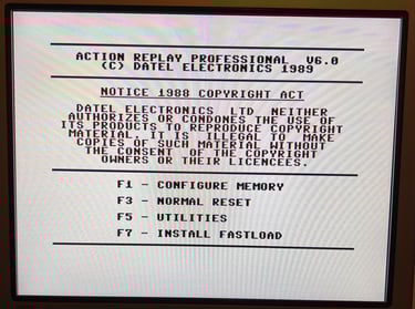
Last basic check before moving to more extensive testing is checking the cartridge. This is done by using the Action Replay VI. Result is that the test is passed.
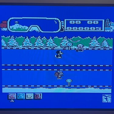
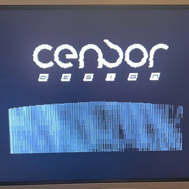
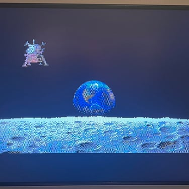
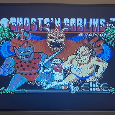
Extended testing
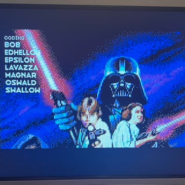
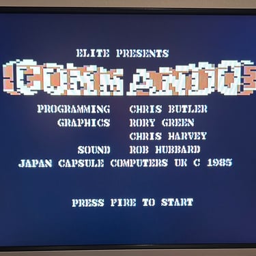
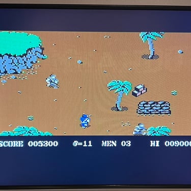
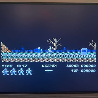
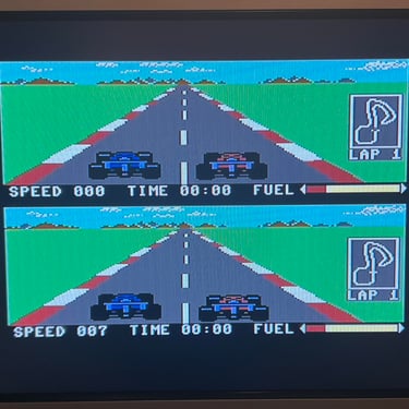
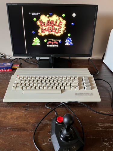
Knowing that the basic functionality of the machine works I continue the testing by using the Commodore 64 for normal operations; playing some games, watching demos, loading from datasette and floppy and using a cartridge. I can not find any issues with this machine. I also pay special attention to the video to make sure that there are no glitches in the graphics - I can´t see any abnormalities. Below is a gallery with pictures from the testing.


Final result
"A picture worth a thousand words"
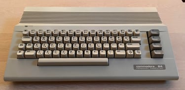
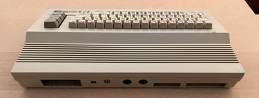
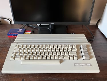
Below is a collection of the final result from the refurbishment of this C64C. Hope you like it! Click to enlarge!

"Are you keeping up with the Commodore? 'Cause the Commodore is keepin up with you!"
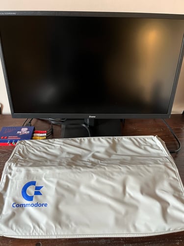
Below are some pictures of the Commodore 64 back at the customer´s home!


