

Signal reference
CIA#2
MOS 6526
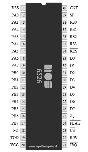
Pinout
Reference signals
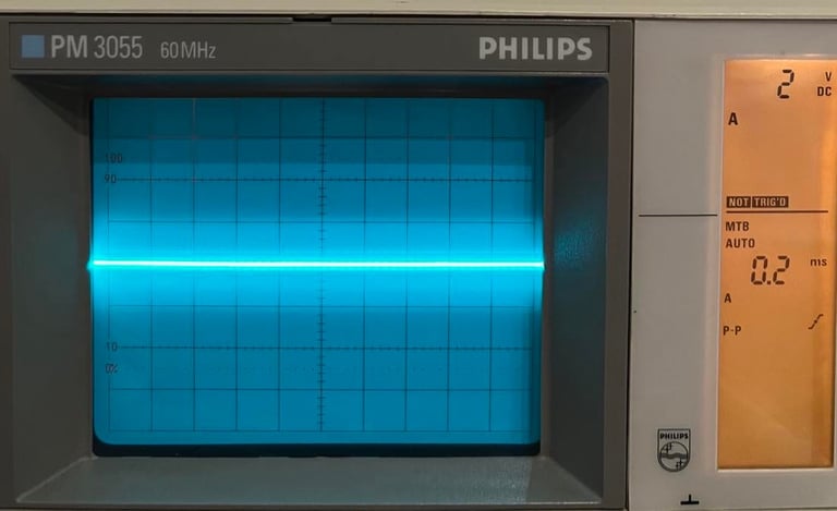
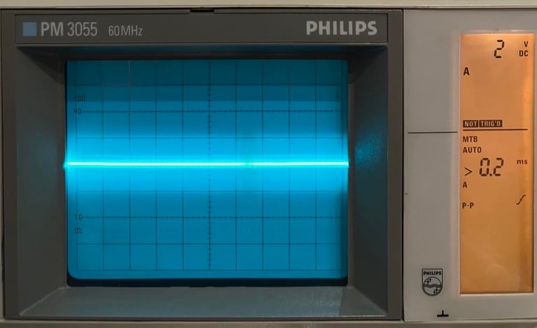
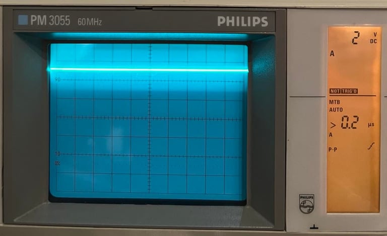
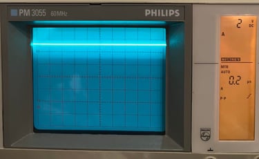
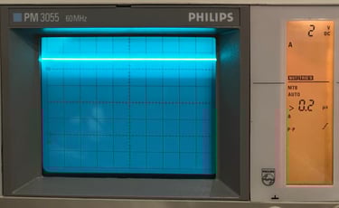
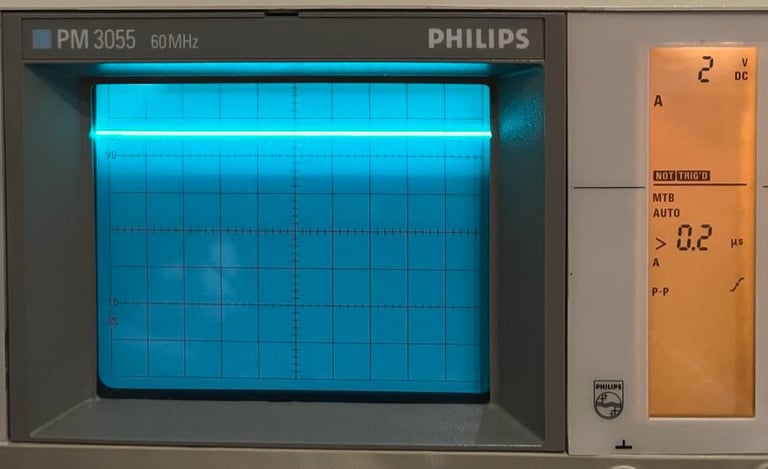
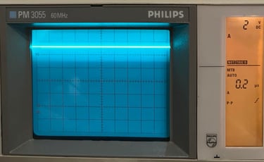
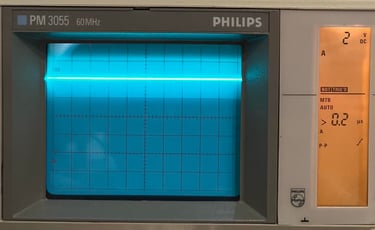
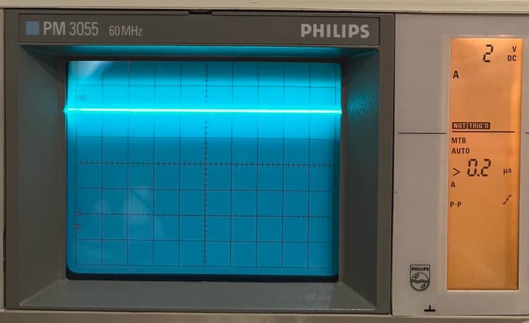
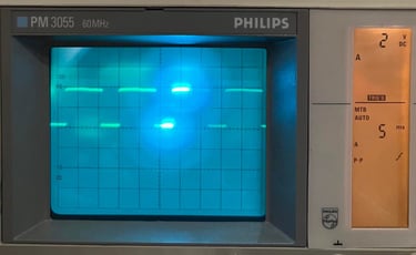
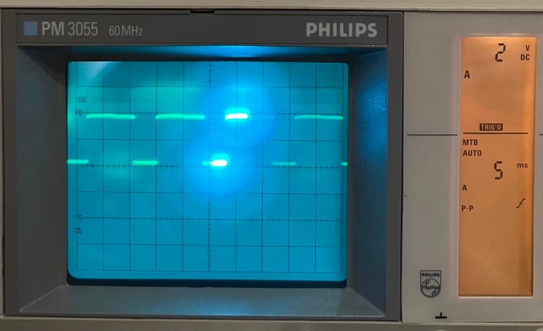
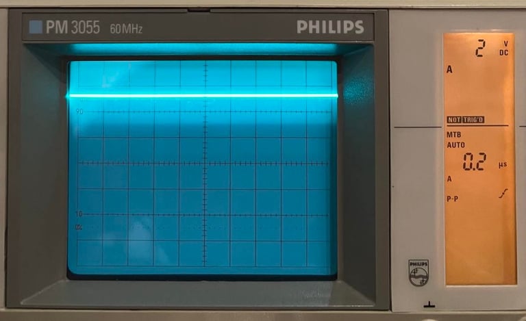
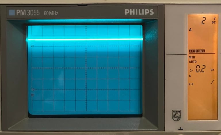
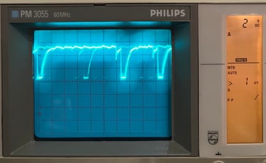
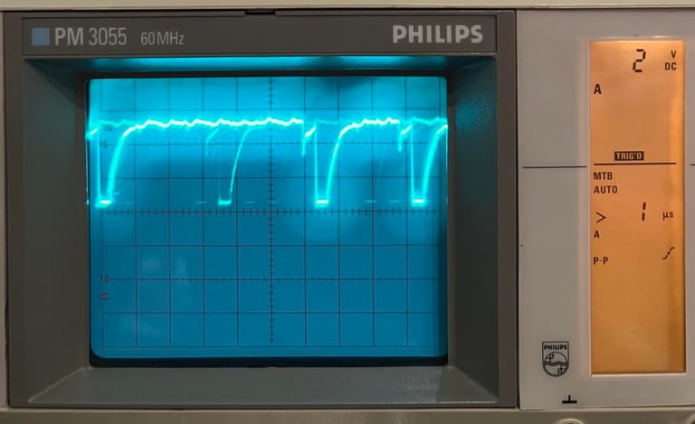
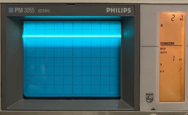
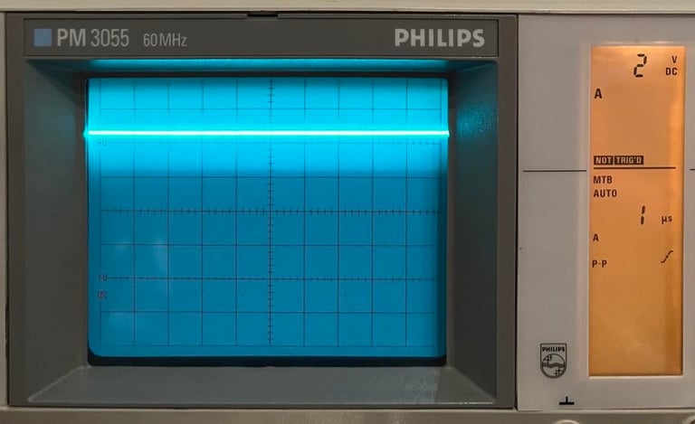
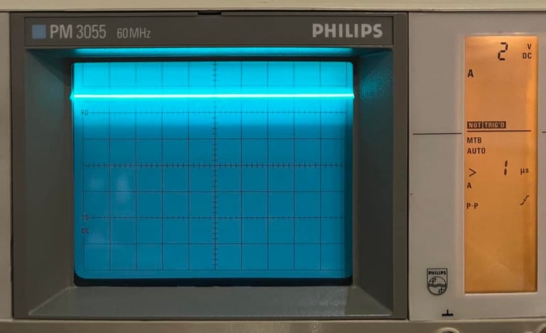
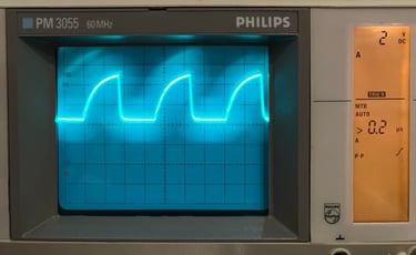
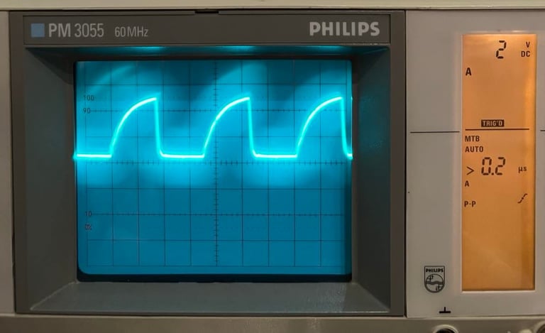
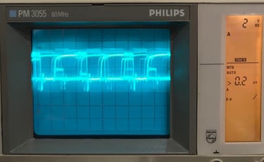
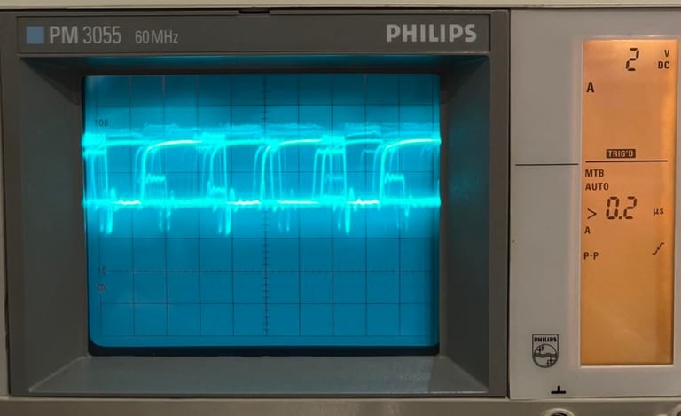
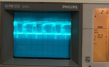
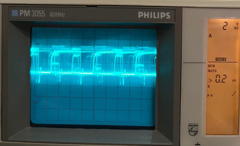
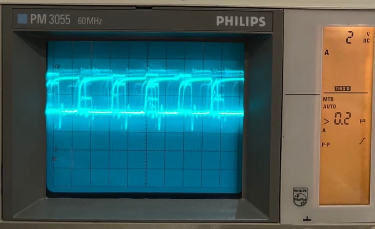
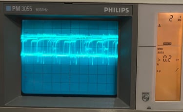
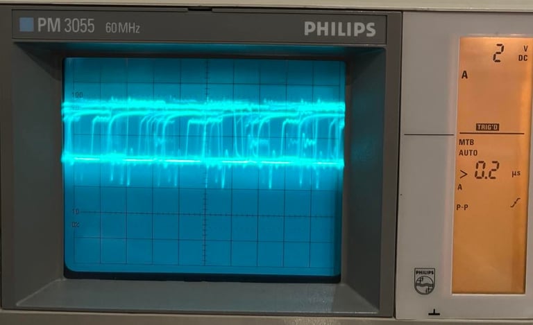
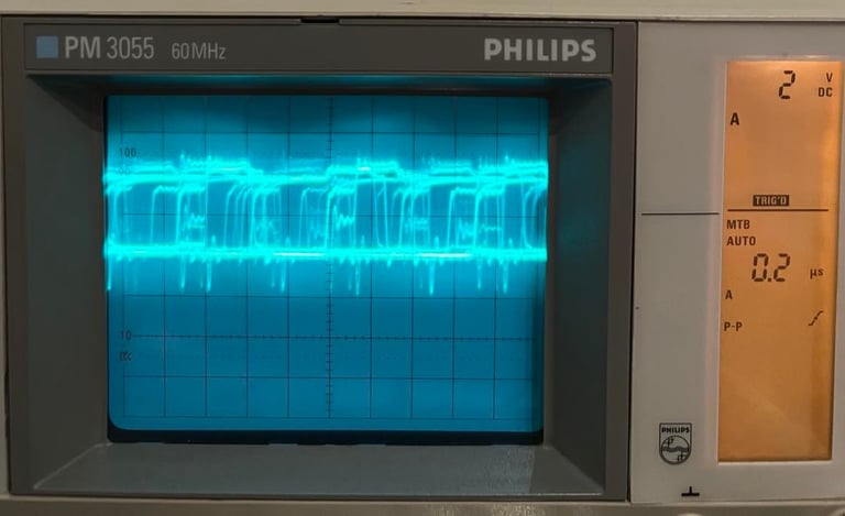
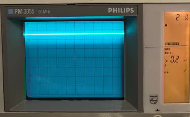
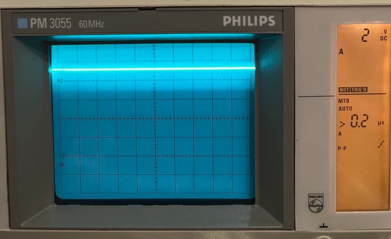
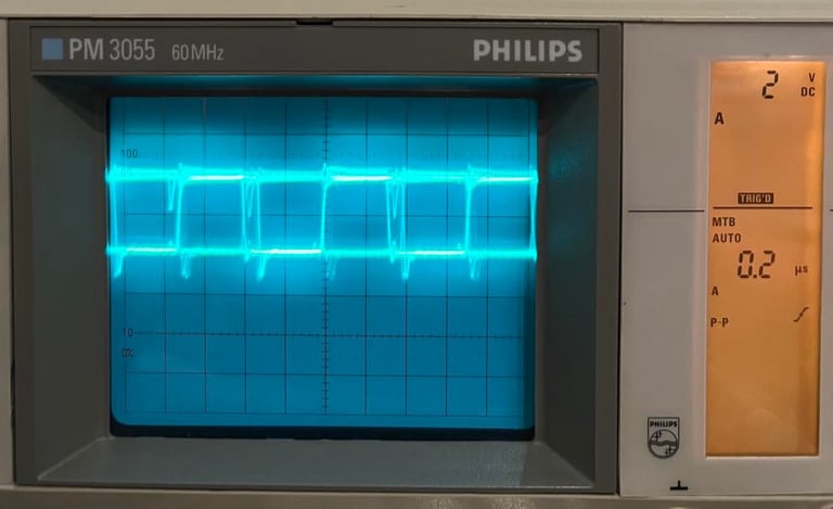
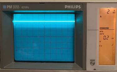
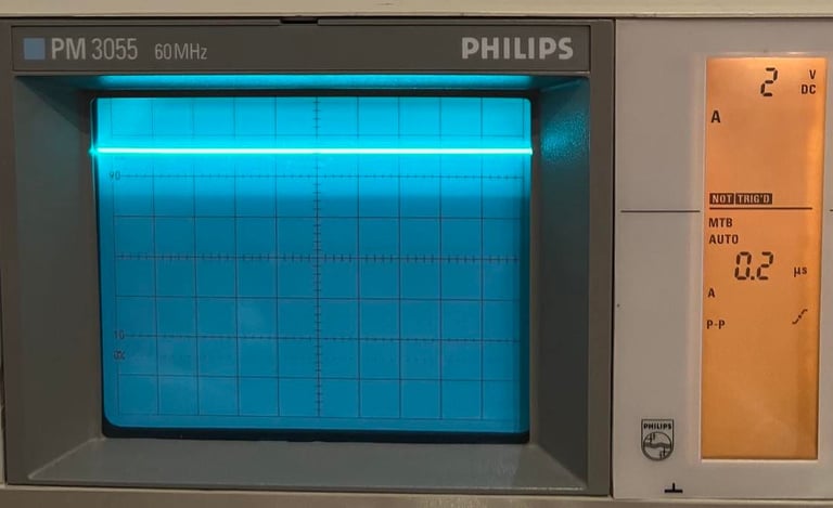
Below are simple pictures of the different signals on the CIA#2 MOS 6526 chip which I use for reference/comparison during fault finding. For further details about the signals on the different C64 custom chips I will highly recommend Sven´s techsite. Information about the pinout is taken from: https://ist.uwaterloo.ca/~schepers/MJK/cia.html and https://www.c64-wiki.com/wiki/CIA.
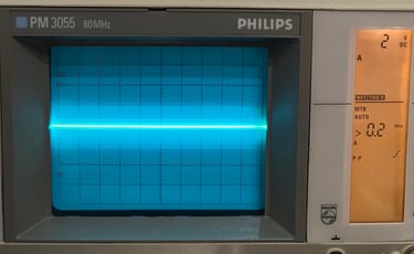
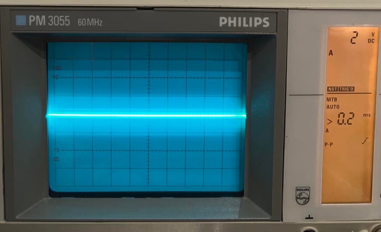
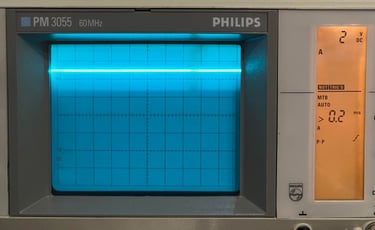
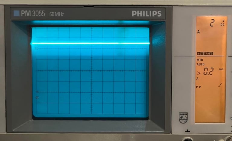
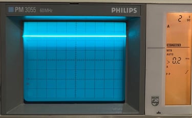
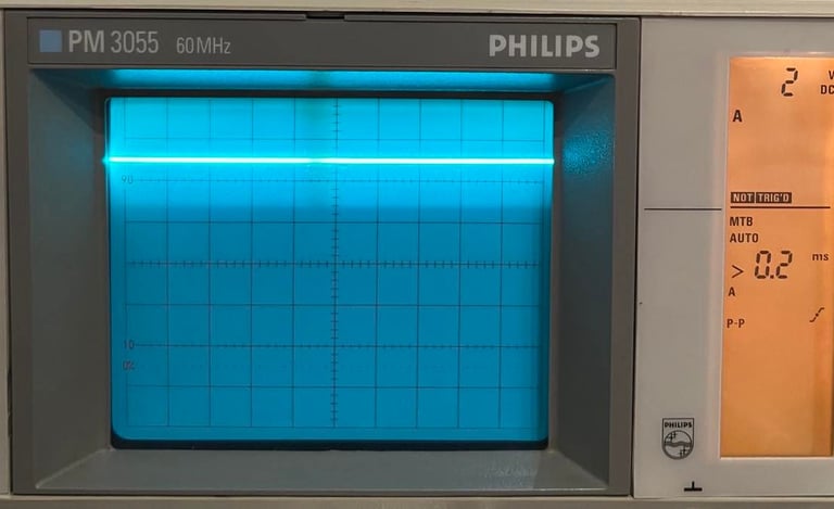
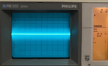
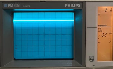
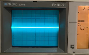
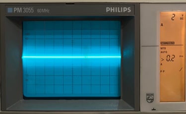
Settings on Philips/Fluke PM3055 60 MHz analog oscilloscope:
2 V / DIV
See individual pictures for time settings
Signals have been measured on a working Commodore 64 assy 250466 in idle mode (blue screen).
Pin #1
VSS/GND
Pin #2
PA0
I/O-Port A Bit0 Bidirectional parallell port

Pin #3
PA1
I/O-Port A Bit1 Bidirectional parallell port

Pin #4
PA2
I/O-Port A Bit2 Bidirectional parallell port
Pin #5
PA3
I/O-Port A Bit3 Bidirectional parallell port
For CIA#2: ATN OUT [Serial bus]
Ground.

Pin #6
PA4
I/O-Port A Bit4 Bidirectional parallell port
For CIA#2: CLK OUT [Serial bus]

Pin #7
PA5
I/O-Port A Bit5 Bidirectional parallell port
For CIA#2: DATA OUT [Serial bus]
Pin #8
PA6
I/O-Port A Bit6 Bidirectional parallell port
For CIA#2: CLK IN [Serial bus]

Pin #9
PA7
I/O-Port A Bit7 Bidirectional parallell port
For CIA#2: DATA IN [Serial bus]

Pin #10
PB0
I/O-Port B Bit0 Bidirectional parallell port

Pin #11
PB1
I/O-Port B Bit1 Bidirectional parallell port

Pin #12
PB2
I/O-Port B Bit2 Bidirectional parallell port

Pin #13
PB3
I/O-Port B Bit3 Bidirectional parallell port
Pin #14
PB4
I/O-Port B Bit4 Bidirectional parallell port

Pin #15
PB5
I/O-Port B Bit5 Bidirectional parallell port
Pin #16
PB6
I/O-Port B Bit6 Bidirectional parallell port

Pin #17
PB7
I/O-Port B Bit7 Bidirectional parallell port
Pin #18
/PC
Port control. Indicates availability of data on port B or both ports.
Pin #19
TOD
Time of day. A TTL signal carrying the mains frequency (derived from the 9VAC) of 50Hz (PAL) / 60Hz (NTSC) is applied here to trigger the realtime clock.
Pin #20
VCC
Supply voltage (+5V DC).


Pin #21
/IRQ
Interrupt ReQuest. Becomes LOW when it matches a set bit in the interrupt control register on occurrence of the corresponding event. In the C64, this line is connected to the CPU's /IRQ pin (CIA #1) or to the /NMI pin (CIA #2), respectively.
Pin #22
R/W
Read/-Write. 0=read on data bus, 1=write on data bus.
Pin #23
/CS
Chip select. 0=coupled to data bus, 1=tri-state.
Chip Select - low level means active CIA.

Pin #24
/FLAG
Negative edge IRQ input, can be used as handshake for either parallel port.
Pin #25
ø 2
Phi 2. System clock signal. All data bus action takes place only when ø2=1.
Pin #26
D7
Databus line D7
Pin #27
D6
Databus line D6
Pin #28
D5
Databus line D5
Pin #29
D4
Databus line D3

Pin #30
D3
Databus line D4
Pin #31
D2
Databus line D2
Pin #32
D1
Databus line D0

Pin #33
D0
Databus line D1
Pin #34
/RES
Reset input, low signal initiates CIA.
Pin #35
RS3
Register select #3. These four pins select one of the CIA's internal registers.
Pin #36
RS2
Register select #2. These four pins select one of the CIA's internal registers.

Pin #37
RS1
Register select #1. These four pins select one of the CIA's internal registers.

Pin #38
RS0
Register select #0. These four pins select one of the CIA's internal registers.

Pin #39
SP
Serial Port - bidirectional, internal shift register converts CPU parallel data into serial data and vice-versa.
Pin #40
CNT
Count - Internal timers can count pulses to this input. Can be used for frequency dependent operations.
Banner picture credits: Xato