

Competition Pro
Refurbishment plan
This joystick looks from the outside quite nice already, but nevertheless to refurbish this joystick the plan is to do this trough the following steps:
- Clean, and remove stains from chassis and all parts
- Check interior for corrosion and repair if required
- Check connectivity
- Verify joystick operation by testing
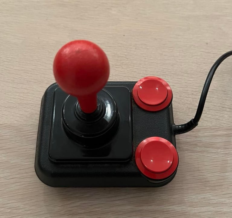
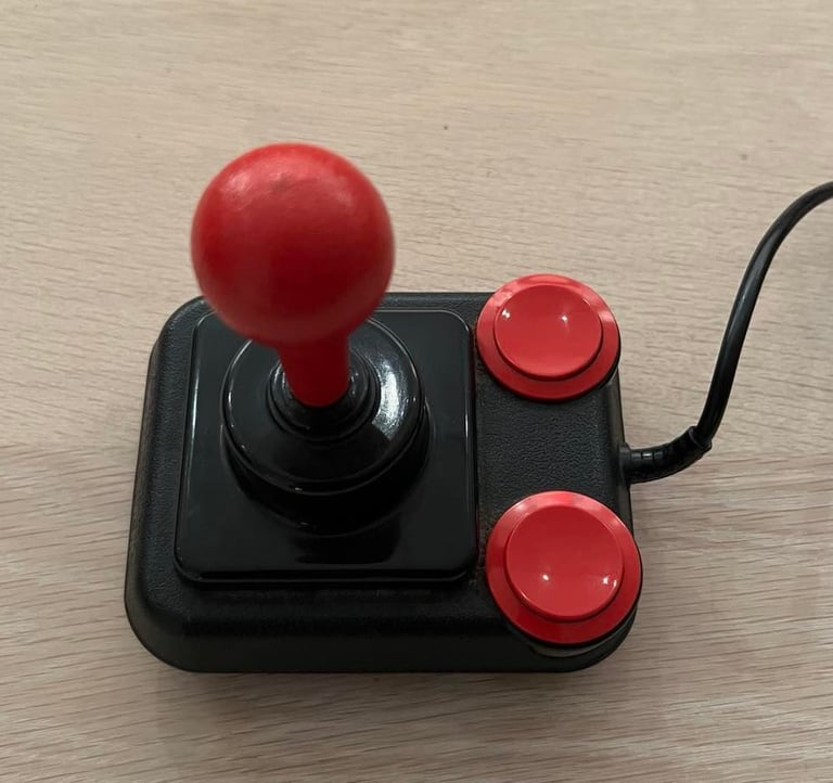
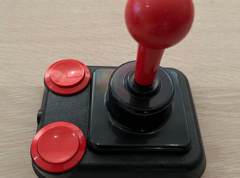
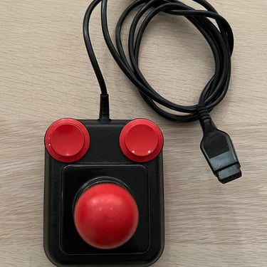
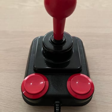
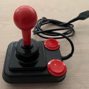
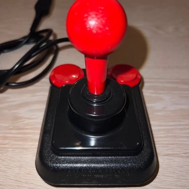
Below is a picture of the joystick before refurbishing - looks quite nice already? This is promising!
Chassis
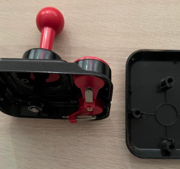
This chassis looks very nice already - even before cleaning. Nevertheless, I disassemble the chassis in the top- and bottom cover by removing the four screws at the bottom. Also, I can´t see any broken parts or damage anywhere.

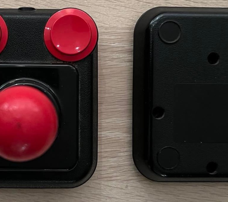

All parts are cleaned carefully with lukewarm soap water first, and then with isopropanol and glass cleaning spray. See result below - looks quite nice I think.

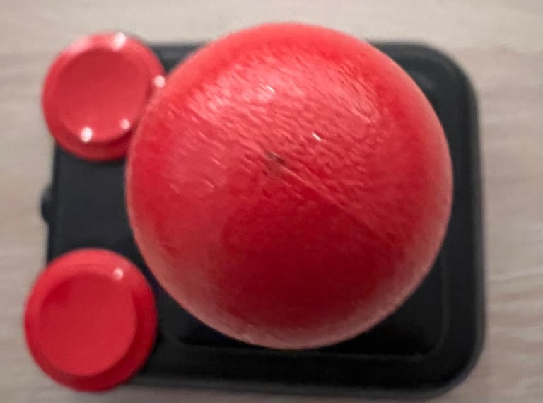
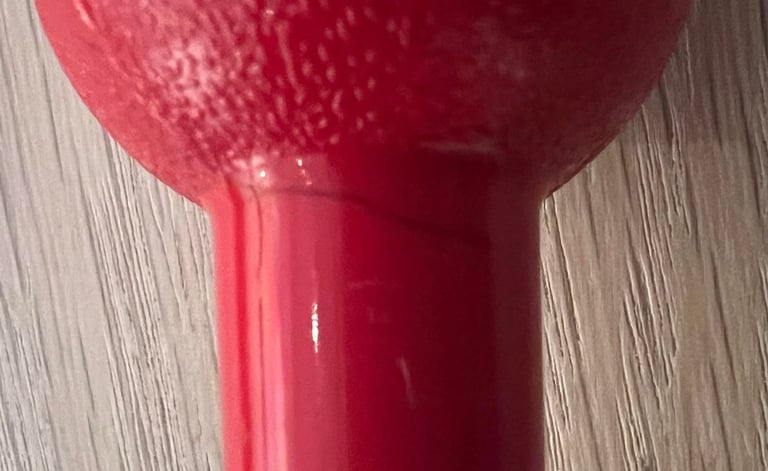
After cleaning I notice two odd marks on the joystick; there´s a small spot on the top ball (see left picture) and there is a "cracking looking" mark on the shaft (see right picture). First, I thought this was a real crack, but I struggle to see that it actually is? To me it looks more like some kind of discoloring, but I´m not 100 % sure. Anyway, I can´t find anything wrong with the shaft so my conclusion is that these are cosmetic marks.


Interior
The interior of this Competition Pro looks good. These joysticks are simple without any PCB, but the quality is good. They are equipped with real microswitches which are really nice and gives a good feedback when playing games.
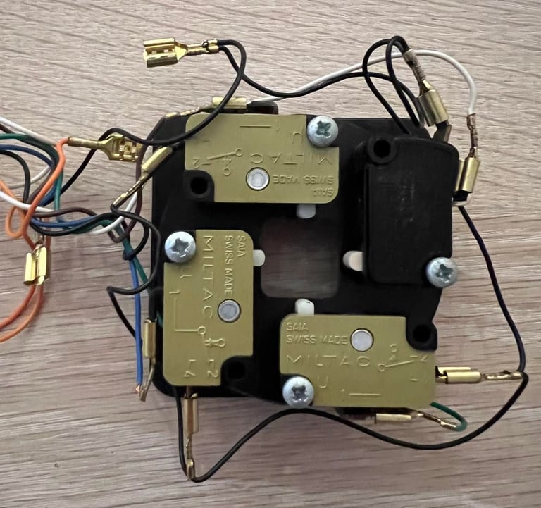
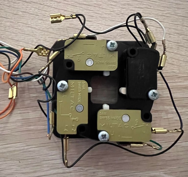
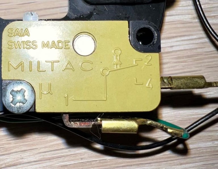
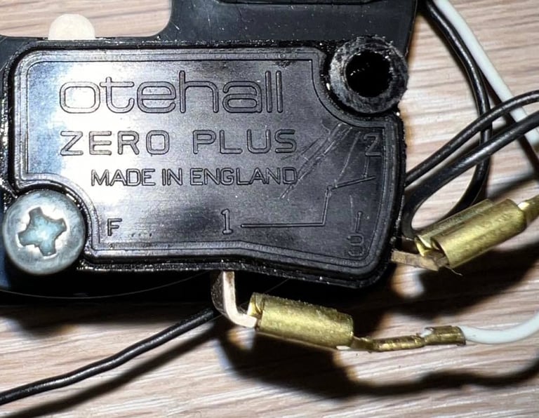
Notice that one of the microswitches are a different brand (and color) than the other; three are "Miltac" Swiss made and one is "Otehall Zero Plus" which is made in England. Why? I don´t know. It can be that one of the switches failed sometime and was replaced. Or it was like this from production just using the switches available. Anyhow, the switches are the same in regards of functionality.
All contacts are cleaned with contact cleaner, and I can´t see any sign of corrosion.
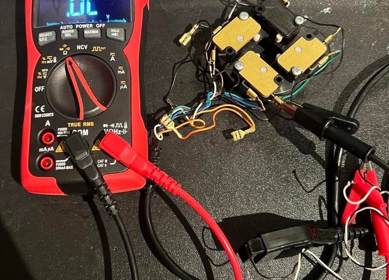
Connectivity
The cable looks undamaged so there is a good chance that it works fine and that connectivity is fine. I could basically just connect it to the C64 and test it, but I think it´s good to do some testing with a multimeter first. This makes it easier also to detect if some of the fine wires are marginal - by using the "beep" mode connectivity test on the multimeter while twisting and bending the cable. The beeping should persist even if the cable is twisted or bent.

All connections are measured to be ok and working - see table below. Note that in the schematics above the pinout shown is from the Commodore 64 side. So when measuring directly on the cable plug the pinout is mirrored.
Below is the pinout for the DB9 joystick connector. Note that there are nine pins on this connector, but it´s normal that only six or seven are used in joysticks used for the Commodore 64. For this one I expect only six cables since the seventh is normally used for +5V to power an autofire function. But since this joystick don´t have an autofire function I expect only the pins for FIRE, UP, DOWN, LEFT, RIGHT and Ground to be present. The schematic is borrowed from: https://ist.uwaterloo.ca/~schepers/MJK/control_ports.html
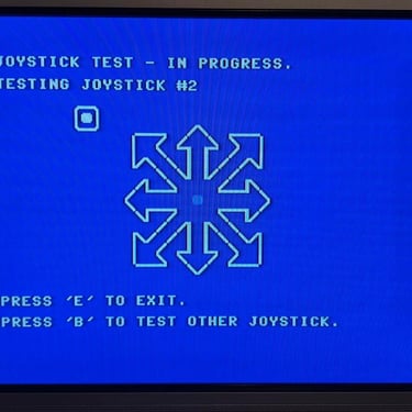
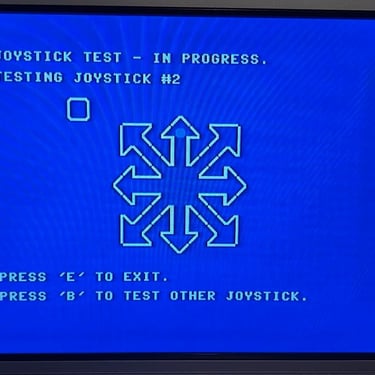
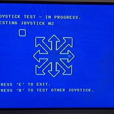
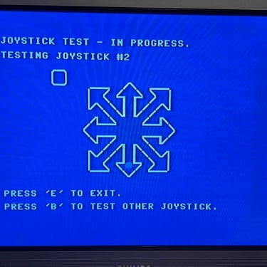
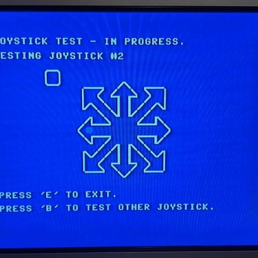
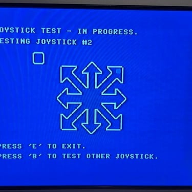
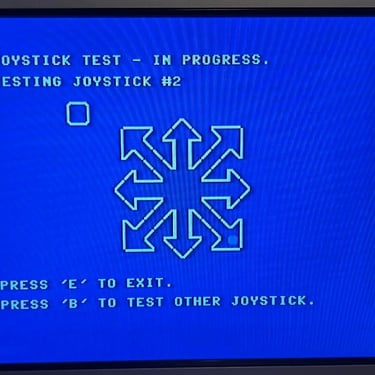
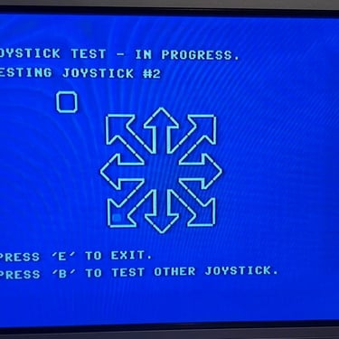
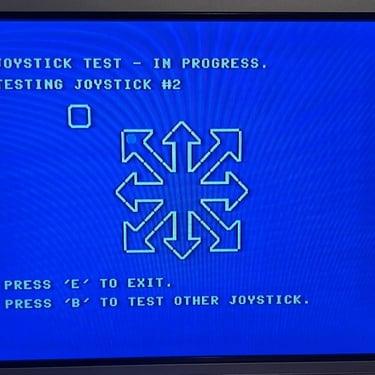
Testing
After everything is assembled again it´s time to verify that the joystick works as expected. And it does! I use the joystick tester from the Doctor64 software. See pictures below from the test process.
Final result
"A picture worth a thousand words"
Below is a collection of the final result from the refurbishment of this joystick. Hope you like it! Click to enlarge!
Banner picture credits: Kshade