

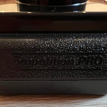
Competition Pro
Refurbishment plan
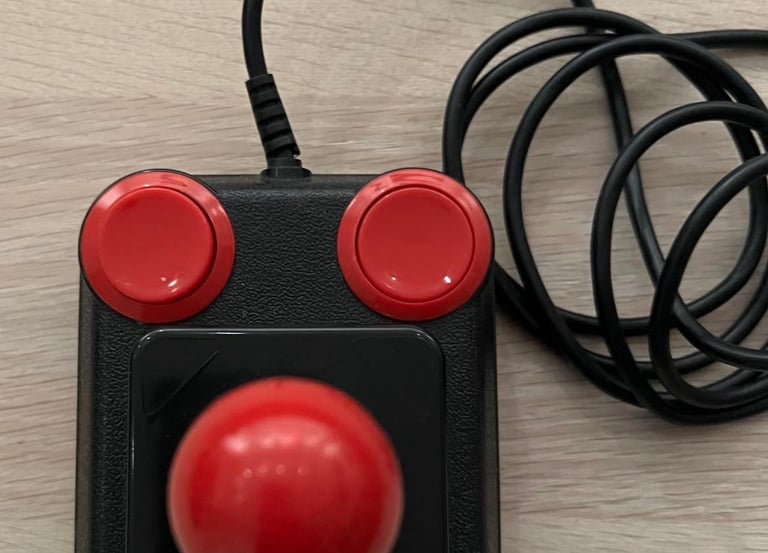
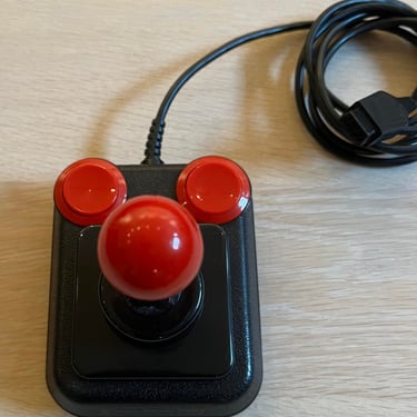
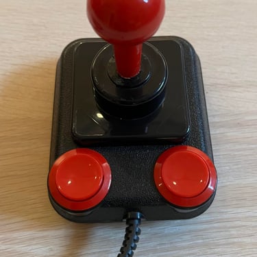
At first glance this joystick looks very nice. But after a closer inspection I notice that:
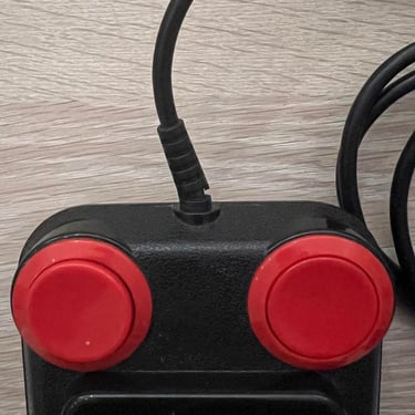
One of the fire buttons are stuck / not responsive
There is a rattling sound from the inside (could it be in relation to the point above)
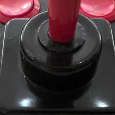
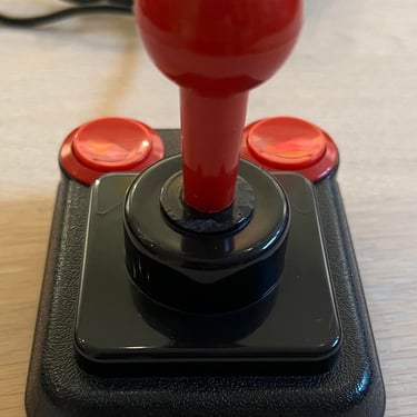
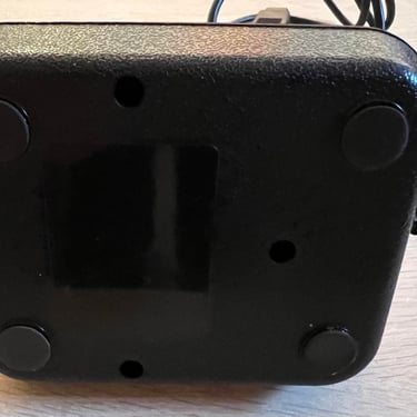
There are som scratches around the shaft. Almost as if some of the plastic has been chipped off
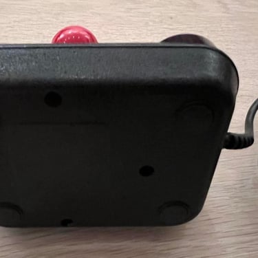
A little part of the strain relief is broken - probably not a problem but should be checked
Beside from this the joystick looks undamaged. Below are some pictures before I start. Let the refurbishment begin!
Refurbishment plan:
- Clean, and remove stains from exterior chassis and all parts
- Check interior for corrosion, damage and repair if required
- Check connectivity
- Verify joystick operation by testing
Exterior chassis
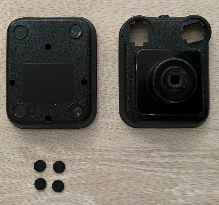
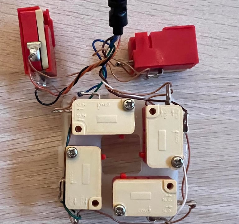
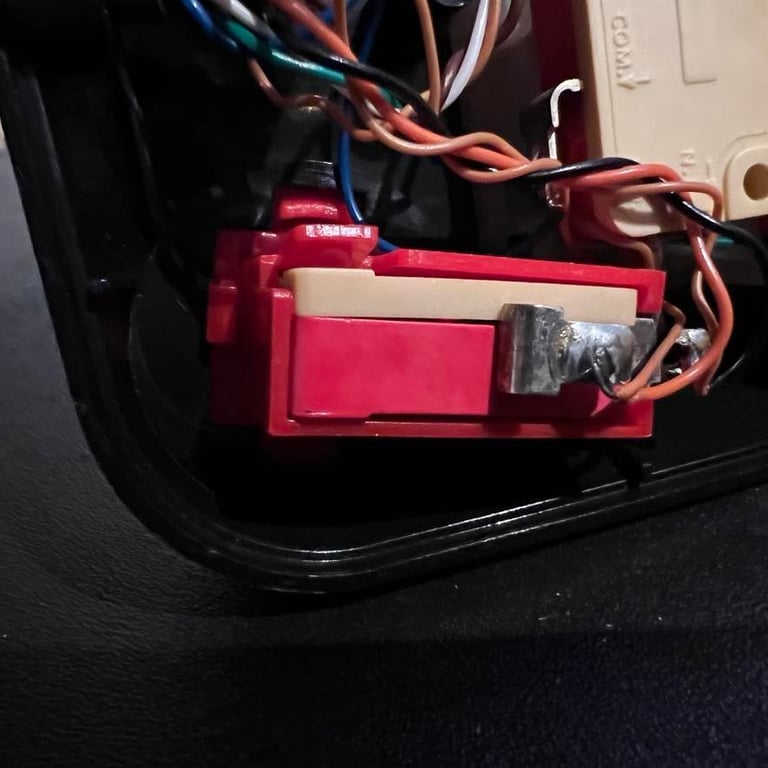
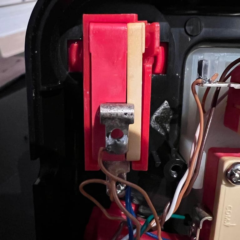
The joystick is disassembled by first removing the four rubber pads which each conceal a screw. When these four screws are removed the chassis is separated in the top- and bottom cover. Immediately I see why one of the fire buttons dont´t work and why there is a rattling sound:
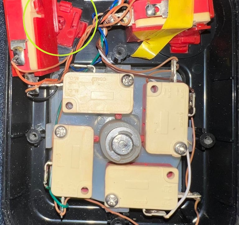

As seen on the picture above (colored circle) the micro switch is no longer attached to the fire button. Luckily, it seems not to be broken and hopefully it can be re-attached. The joystick is completely disassembled - see picture below. All parts will be cleaned with mild soap water (the picture is taken before cleaning).

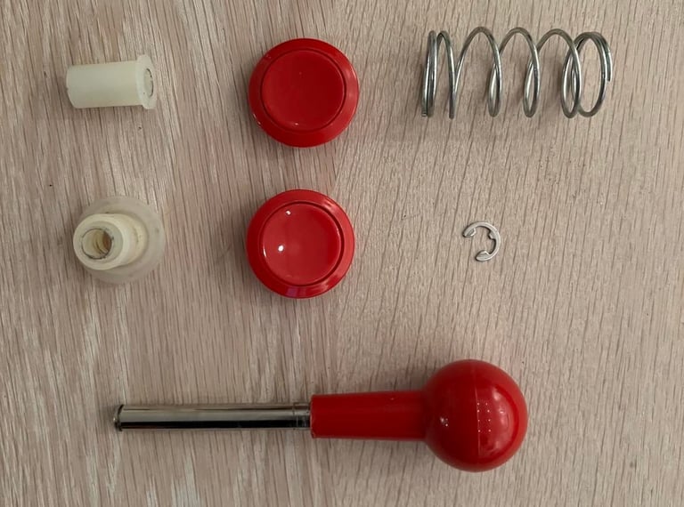
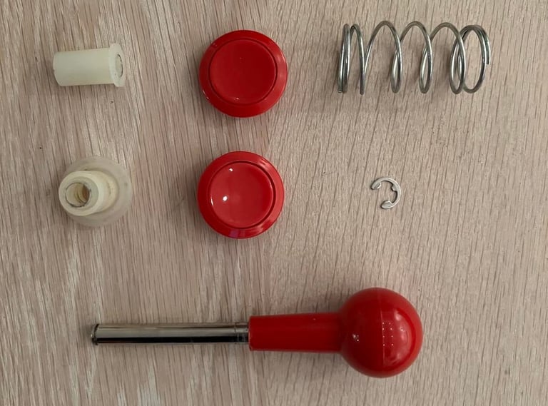
It´s not much to do with the chipped off marks below the shaft. I don´t want to start sanding or anything like that - I think it´s best just to leave it. It´s clean and works! The result of the cleaning of all parts are best shown in the pictures in the "Final result" part.
Interior and microswitches
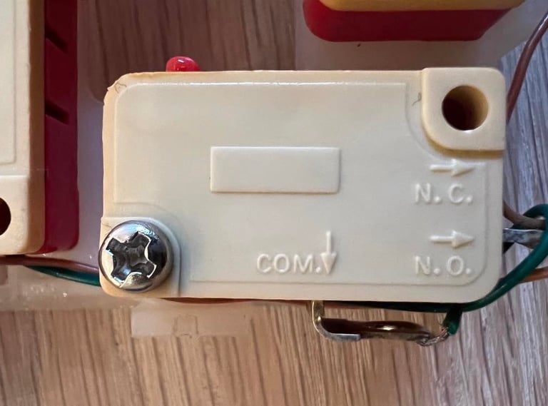
These Competition Pro joysticks have no PCB, but have microswitches directly connected to the cable. All switches looks to be in good condition and are only cleaned with isopropanol and contact cleaner. Also, I can´t see anything damaged with the plastic casing either on the switch for the fire button so hopefully this joystick can be repaired. All the cables are soldered on instead of being clamped on. I would assume that this is from factory and not as a result of a repair since all are soldered.

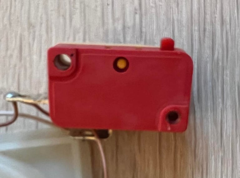
I can´t find any brand name on the switches. There are text describing the different connectors, but no sign of a name. Which I think is strange because these switches feels like good quality microswitches (with a good "click"). Note; the picture of the backside of the switch is a bit blurred. But trust me, there is no brand name...


Further on, I can´t see any sign of corrosion or bad soldering. So I do not do any repair here as long as nothing seems broken (we´ll see after checking connectivity and final testing).
Connectivity
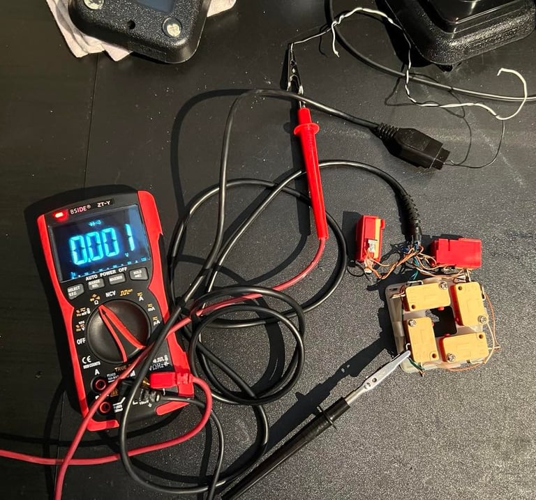
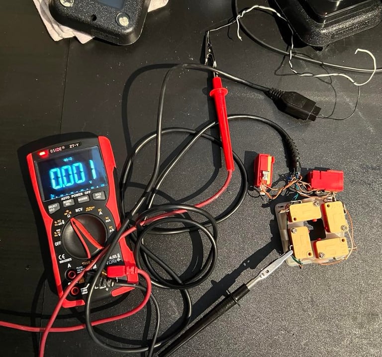
Before I reassemble the joystick I check the connectivity. I need to know that the cable is ok - that the connection is good between the microswitches and the plug. By the word "good" I refer to checking the connectivity with a multimeter in "beep" mode. In this mode I know that the resistance in the cable is very low (typically less than 50 Ohm) and also I can listen to this beeping noise while wiggling with the cable. The beep should continue even if I wiggle the cable.
It´s not complicated to check the connectivity, but it´s good practice to check each and every cable. I use the schematics below to keep track of which pin is which. Note that in this schematic the pinout is from C64 side. So if you measure directly on the joystick cable as I do the pinout is mirrored. The schematic is borrowed from: https://ist.uwaterloo.ca/~schepers/MJK/control_ports.html. Also, you may notice that in this schematics they use descriptions such as "JOYA0", "JOYA1" etc. In the connectivity table I use you can see how these translates to UP, DOWN, LEFT, RIGHT and FIRE.
A final note: there is no +5V wire on this joystick from the C64. This is normal. Since this joystick have no auto-fire functionality, there is no use for the +5V so it´s not connected. Instead, when a direction is chosen (e.g. direction LEFT is enabled) this pin is connected to Ground (e.g. pin # 3 is short circuit to GND).

Below is a picture from the testing process. Not complicated, but a bit time consuming...
The microswitches are installed back in the chassis, and it turns out that NOTHING IS BROKEN! Both the fire button switches just "clicks" into place. So how on earth this switch fell out of place in the first place I really don´t understand? Perhaps under some heavy game play? If they should for some reason fall out it´s easy to "click" them back into place. I thought of having some tape to ensure them - but I don´t really see the point. They look to me to sit tight the way they were designed to snap into place. Below are two pictures showing the fire button switches in place.
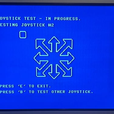
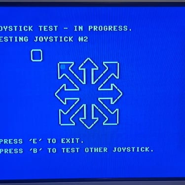
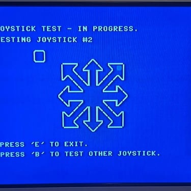
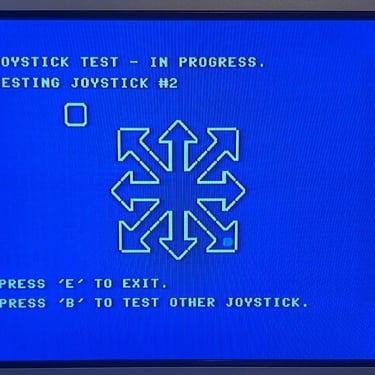
Testing
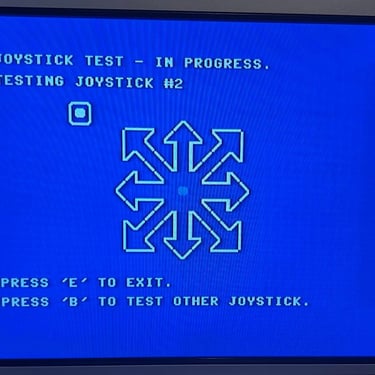
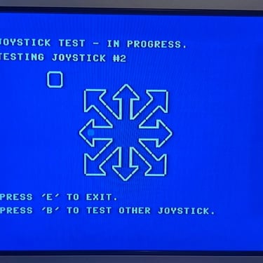
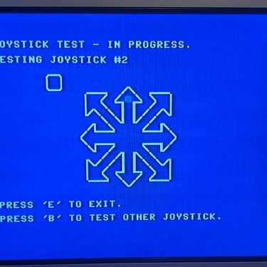
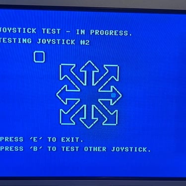
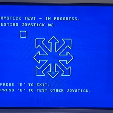
In theory the joystick should now work. The connectivity testing have confirmed that all connections are ok, but it´s always wise to verify that the joystick works on a real Commodore 64. And let´s be honest; this is also a very good excuse to play some magnificent C64 games! Nevertheless, I use Doctor64 software ase the formal testing software. See pictures below for the results. All is ok!
Final result
"A picture worth a thousand words"
Below is a collection of the final result from the refurbishment of this joystick. Hope you like it! Click to enlarge!
Banner picture credits: Kshade