

Competition Pro
Mini
Starting point
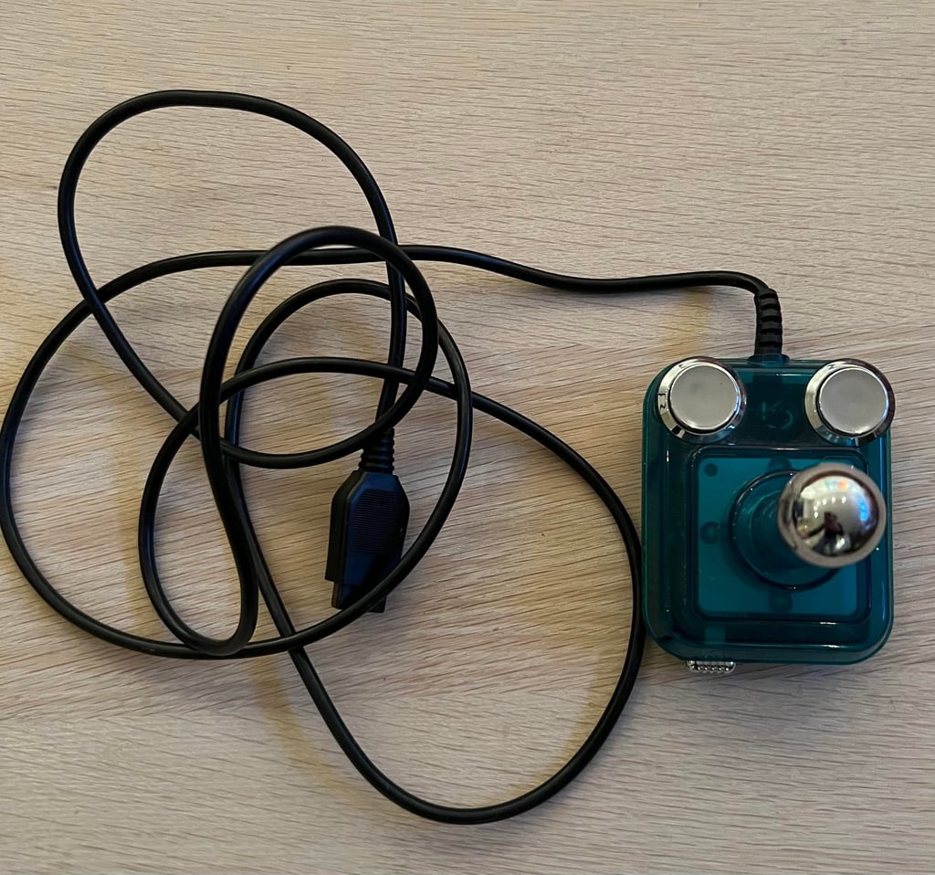
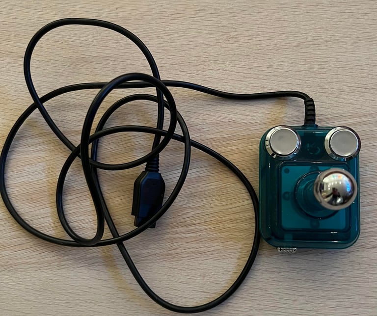
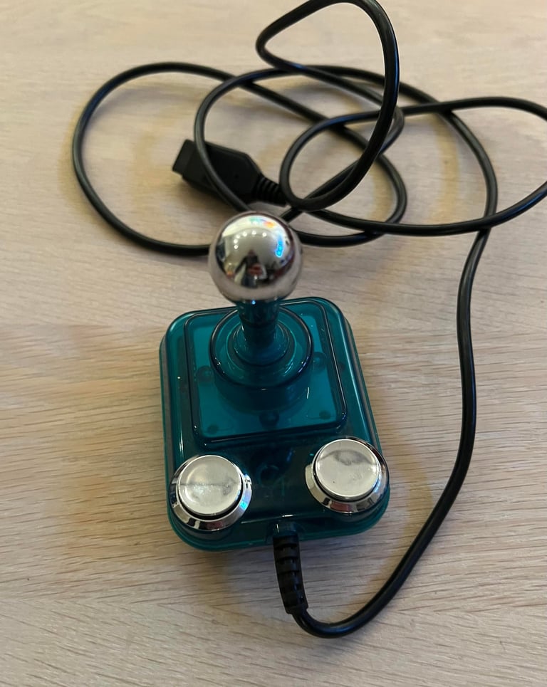
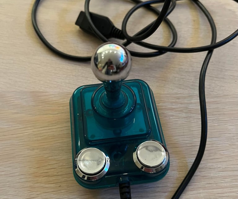
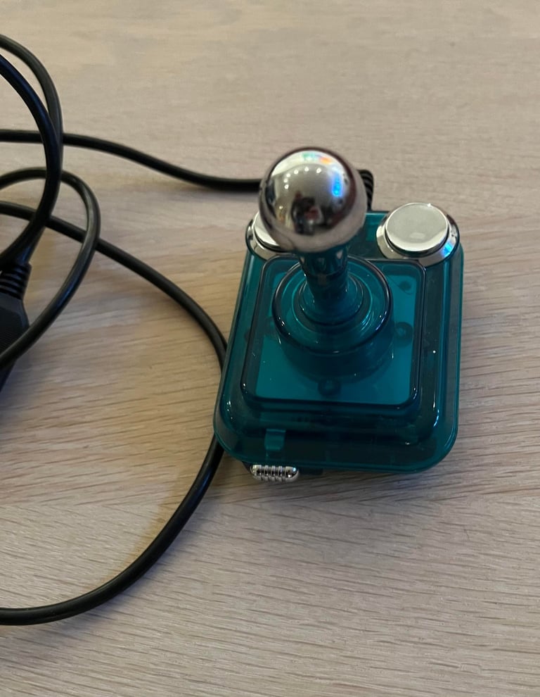
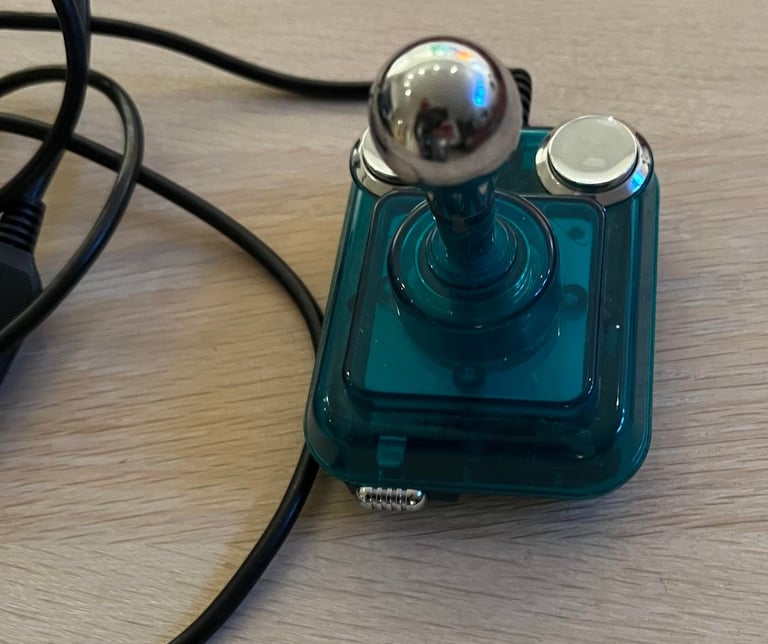
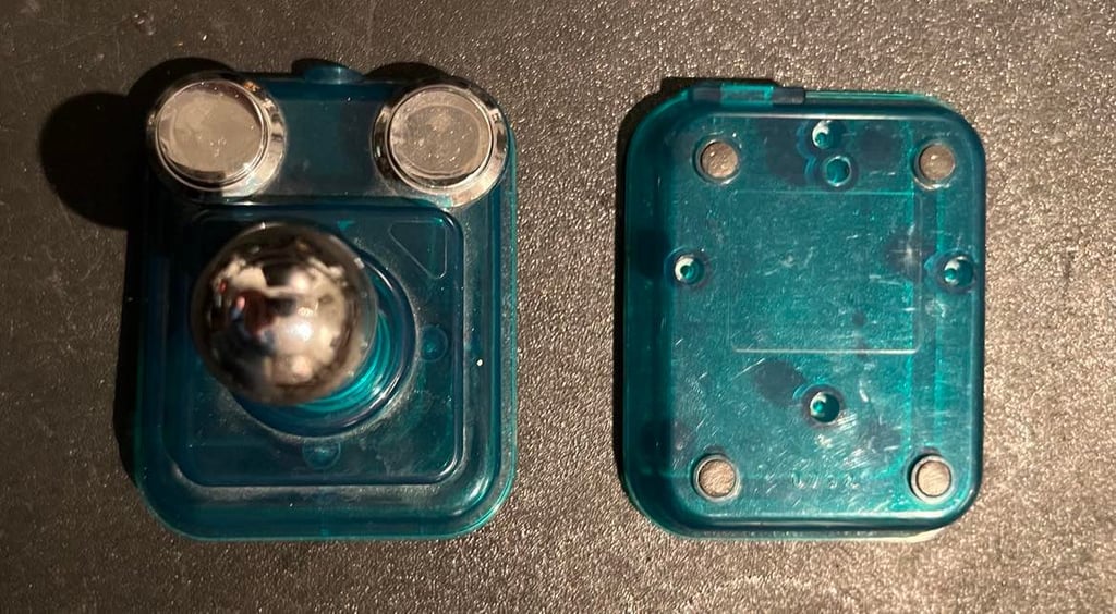
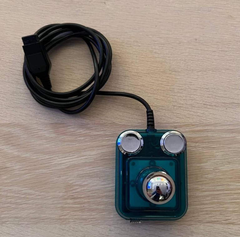
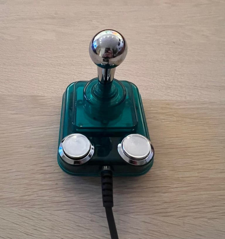
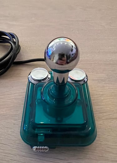
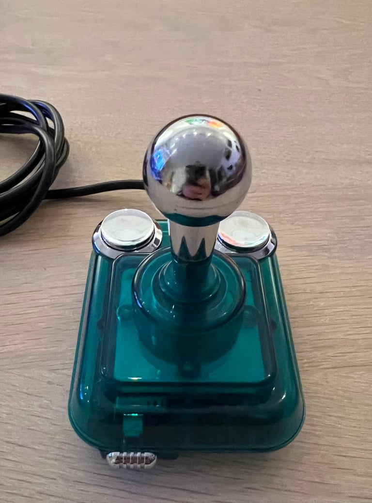
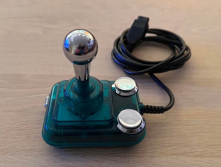
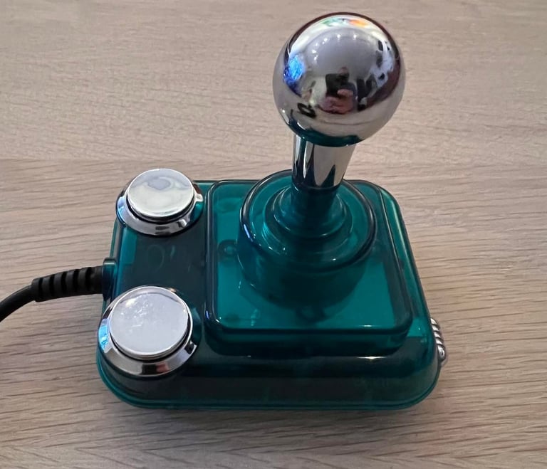
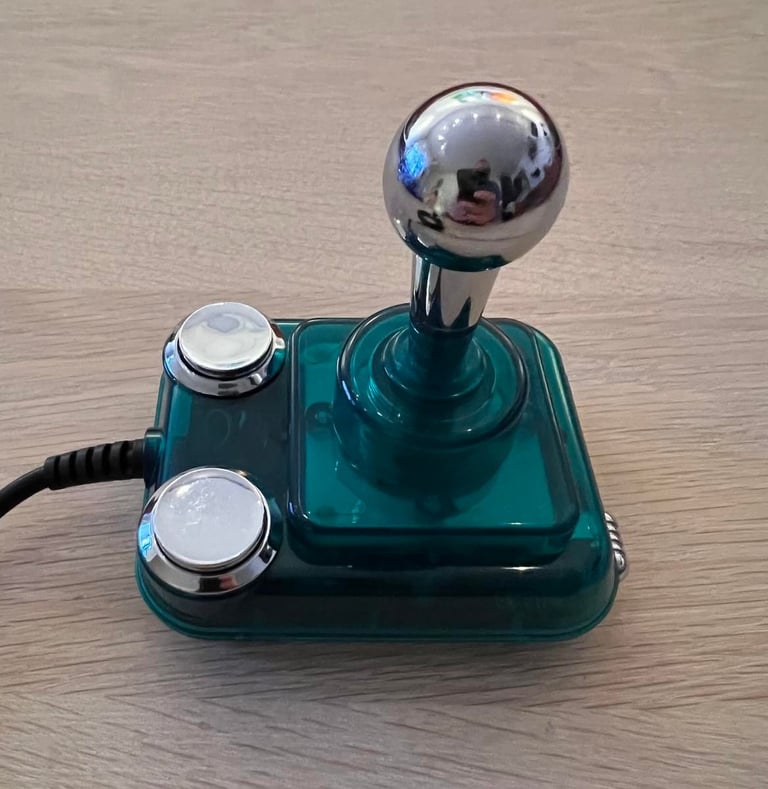
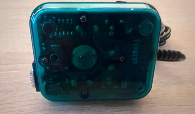
From the outside this CompetitionPro Mini joystick looks very nice. But, I already know that it doesn´t work on the inside. Previous owner started the repair, but decided to leave it to me (thanks!).
I know from experience that these joystick do have the tendency to fail. Even if there are microswitches in this joystick, they are very small compared to the big brother (Competition Pro). Nevertheless, I think some of the switches can be replaced with new switches and with some 3D printing magic it will hopefully work! Time will show!
Below are some pictures of the joystick before the refurbishing begins.
Refurbishment plan
To refurbish this joystick the plan is to do that through the following steps (some of them in parallell):
Clean the exterior chassis
Repair, check and clean interior electronics
Check cable connectivity - replace cable if broken
Verify operation by testing
Exterior casing
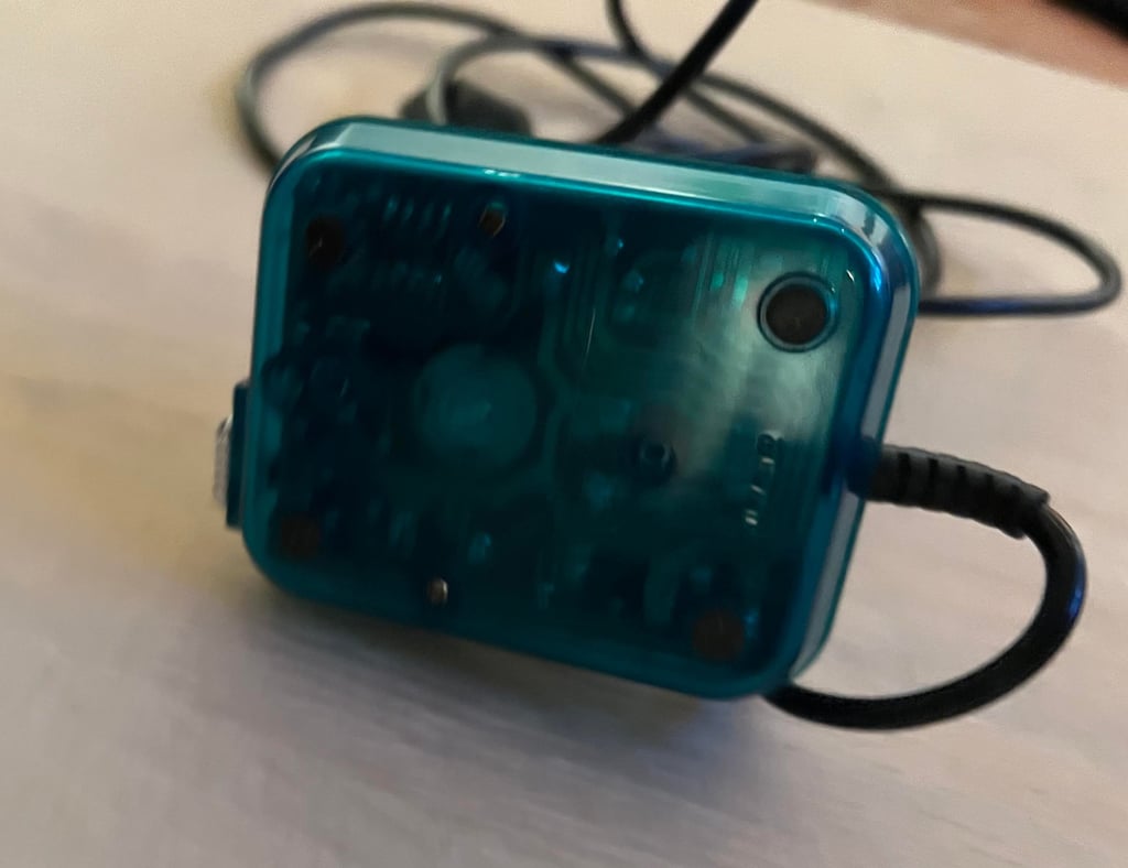
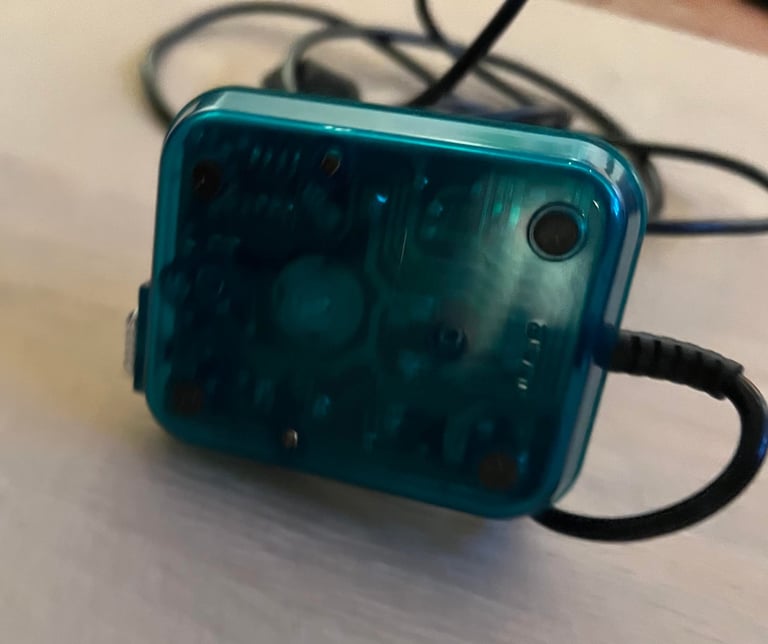
The exterior casing consists of a top- and bottom cover. These are connected by four screws at the bottom, but there are at the moment only two screws.

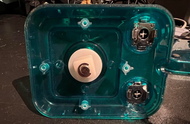
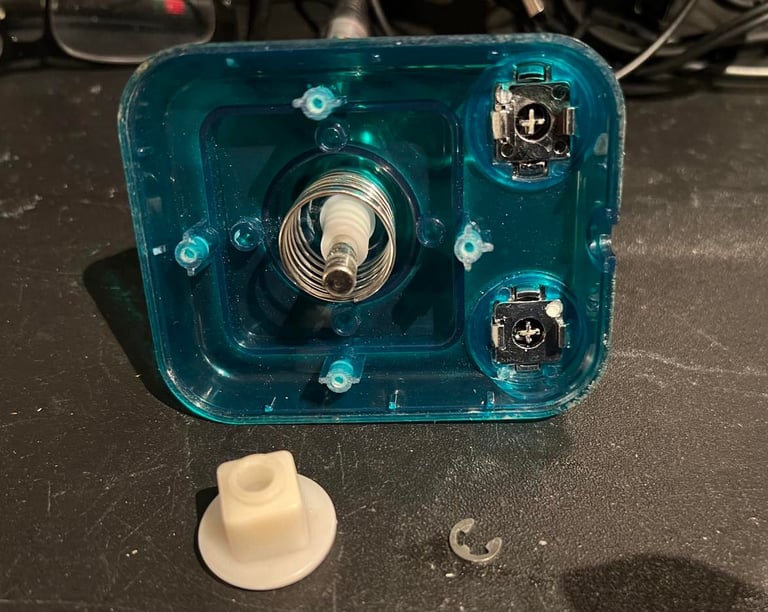
To get a proper cleaning the joystick shaft is also disassembled. This is done by first removing the metal clip from the rear of the shaft. Then the plastic parts and the spring is removed. See pictures below.

All parts are cleaned with mild soap water. The top- and bottom cover in plastic is also cleaned with some glass cleaning spray.
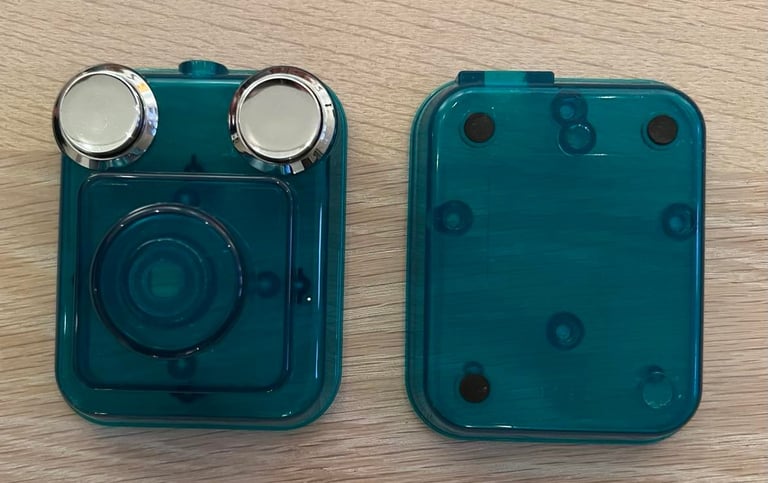
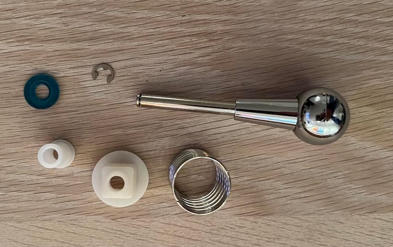
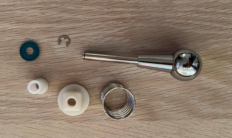
I notice that one of the rubber pads are lost. I think it is my fault - it´s probably gone while washing it. Annoying...
Interior electronics
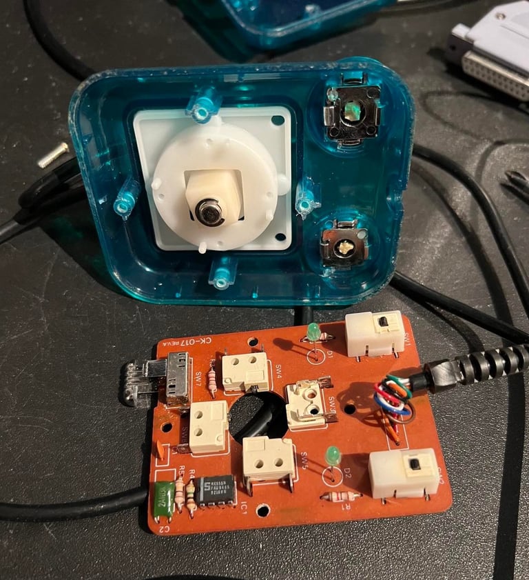
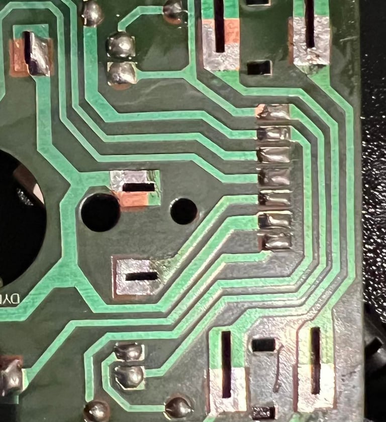
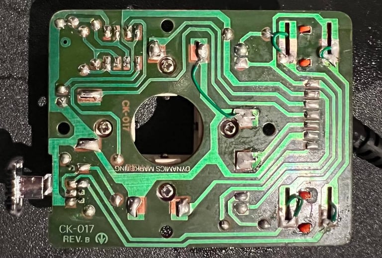
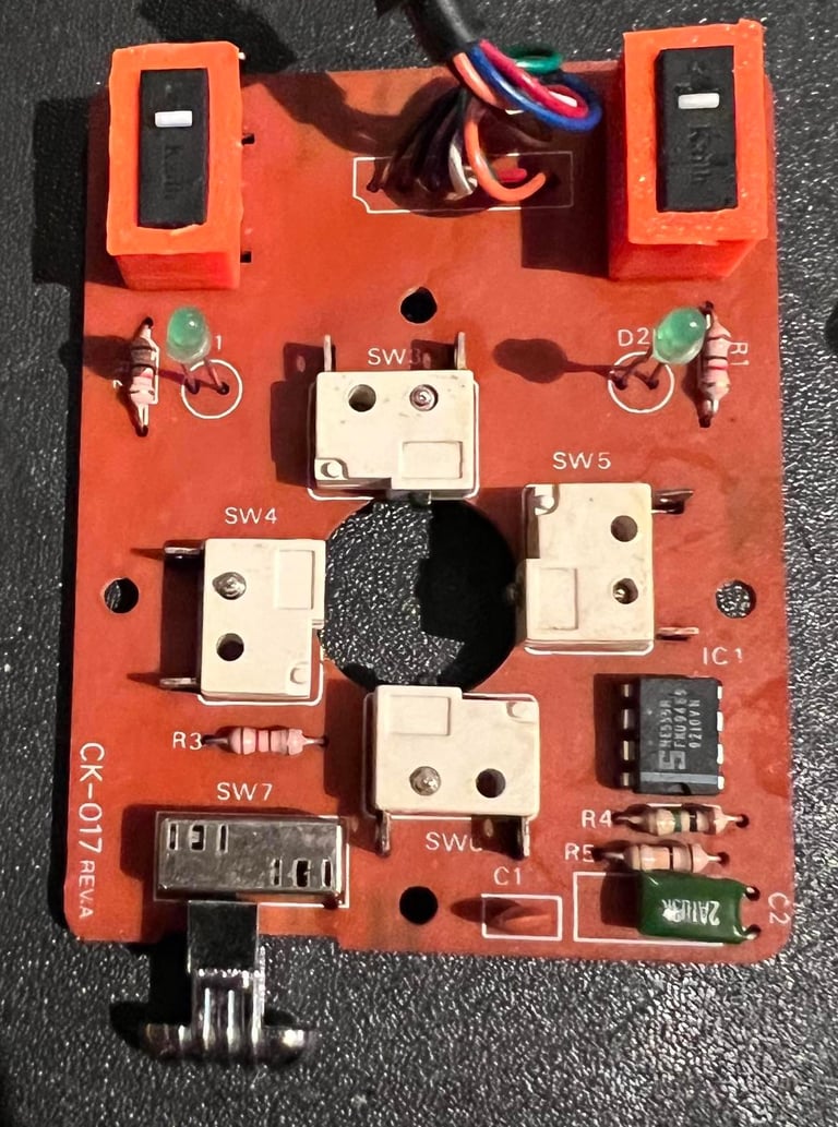
The PCB is marked with "CK-017 REV A" on the front and "REV B" on the back. Why? I don´t know. First thing I notice when opening the joystick and see the interior is that one of the microswitches is missing. Or more precisely; parts of it are missing.
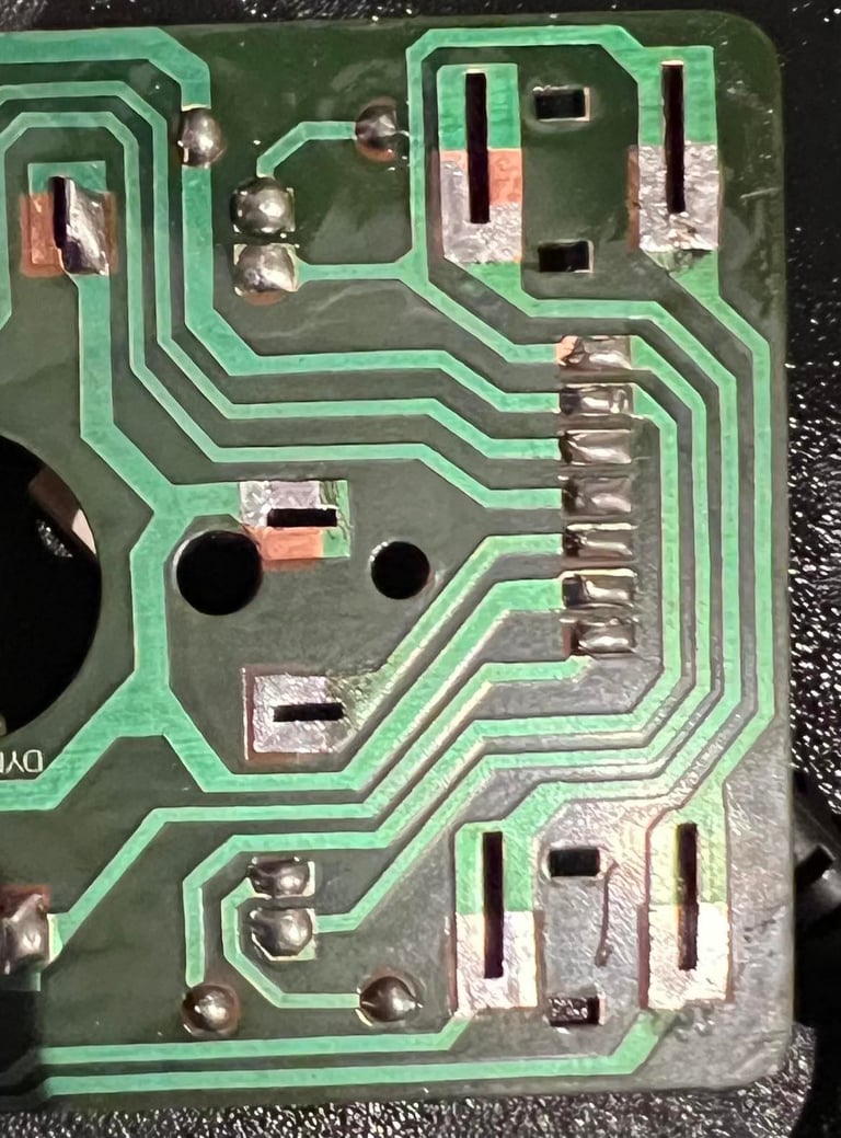
Also, the fire buttons don´t work properly. These switches are old so that some of them stops working is not uncommon. I decide to remove both fire button switches and the "DOWN" direction switch. Unfortunately, when desoldering the "DOWN" switch I see that one of the pads rips. This is not a problem since it can easily be repaired with a bodge wire. The picture below shows the PCB after these components are removed. Note that it is not easy to see that one of the pads are broken in this picture since the pad is flush with the PCB - but it is broken.
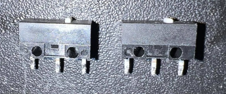
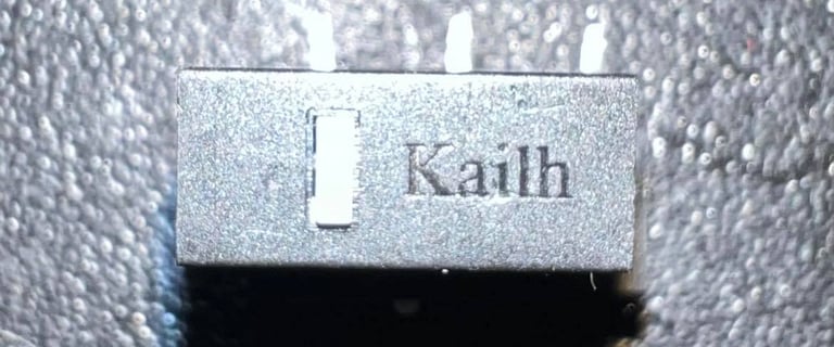
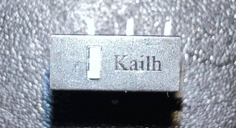
To replace the two fire buttons I choose to use switches from Kailh. I have two of these previously taken from a Lenovo mouse. These are high quality switches - but I need to find a way to get them onto the PCB since the form-factor is different.
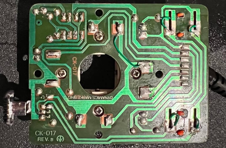
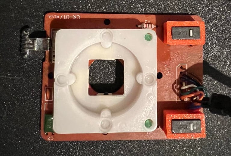
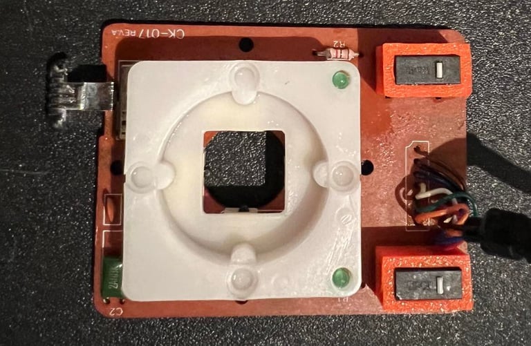
A "new" microswitch for the "DOWN" direction is taken from another Competion Pro Mini joystick which I have and used in this joystick instead. Below are pictures from front and back of the PCB with the new switches
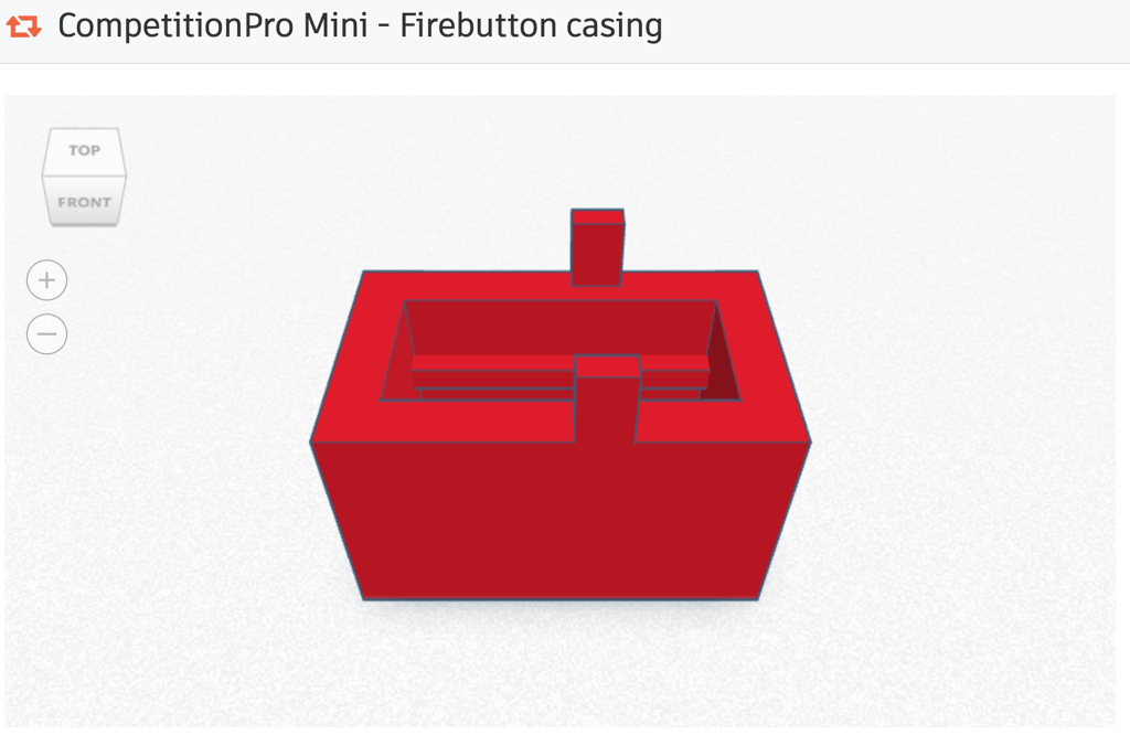
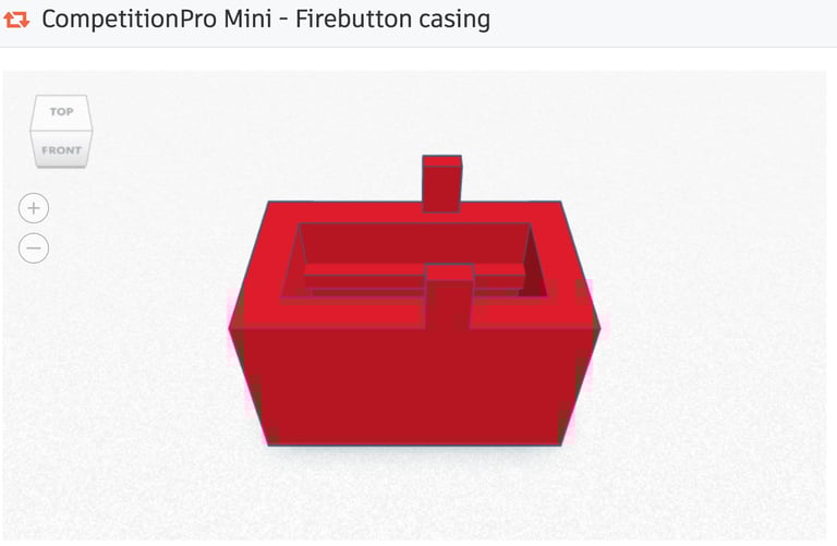
I choose to 3D print two plastic brackets to hold the fire buttons. The plastic brackets are designed by me using Tinkercad. (The STL file can be downloaded here).
The 3D printed brackets are given a small drop of super glue to make them stay in position.
This joystick also have an auto fire functionality. This feature is made from a 555 timer chip in combination with a resistor / capacitor circuit. There are no visual damage/corrosion around the chip and circuit - testing will reveal later if this works.
UPDATE AFTER TESTING:
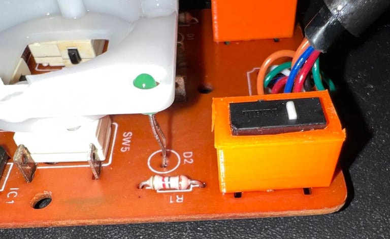
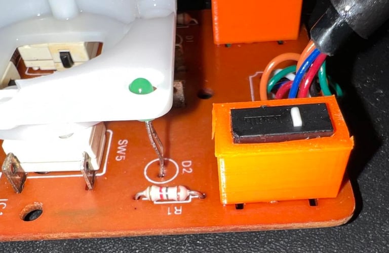
The testing revealed that the LEFT direction was not working as it should. So a "new" microswitch is soldered in. See picture below (marked as SW5).

Connectivity
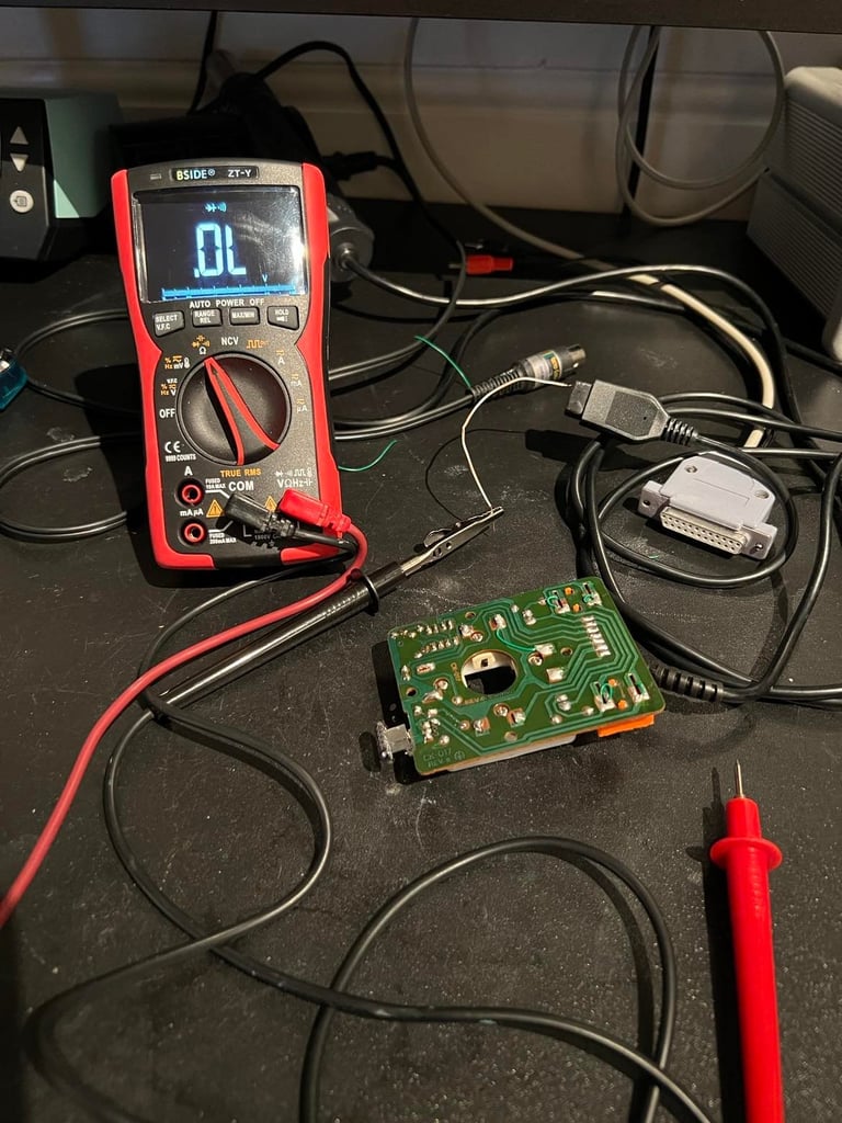
The connector, cable and wires are checked to make sure connectivity is ok. I use a multimeter set in "beep" mode to make sure all the wires have good connection - even while the cable is twisted and turned. Below is the pinout for the joystick. Note that this schematics is seen from the computer side, so you need to mirror it if you check directly on the cable (which I do).
The connector, cable and wires are checked to make sure connectivity is ok. I use a multimeter set in "beep" mode to make sure all the wires have good connection - even while the cable is twisted and turned.
All seven wires have good connectivity; UP/DOWN/RIGHT/LEFT/FIRE/GND/+5V. Note that this joystick also have +5V DC - this is to give voltage to the 555 timer chip used by the auto fire. Below is a snapshot from the testing process.

Testing
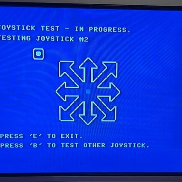
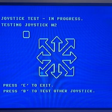
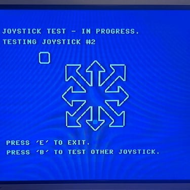
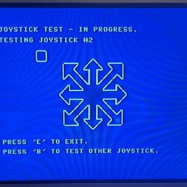
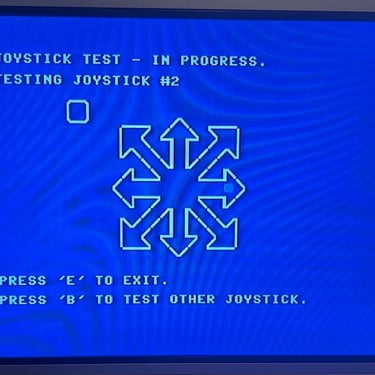
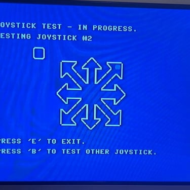
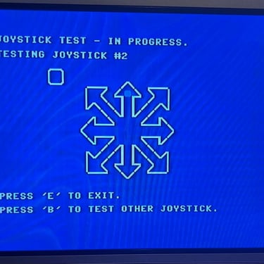
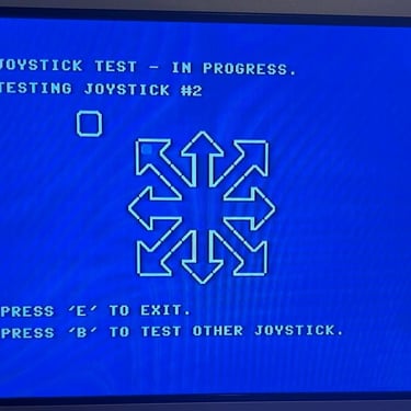
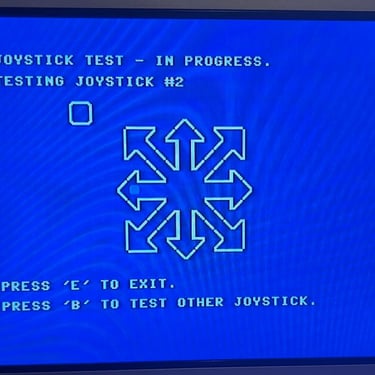
To test the joystick I use the 64 Doctor software running on a Commodore 64. But I notice on first test run that the "LEFT" direction is not working properly. There is response, but it only works about 80 % of the time. So I decide to replace this also switch with a "new" one from another similar Competition Pro Mini joystick. But after the replacement I do a complete test which shows that all directions, fire button and auto fire is working as it should.
But as a general comment my impression is that the quality of these miniature microswitches are not too good. They are ok when they work, but they are very fragile I think.
Below is a gallery of pictures from the testing with 64 Doctor.
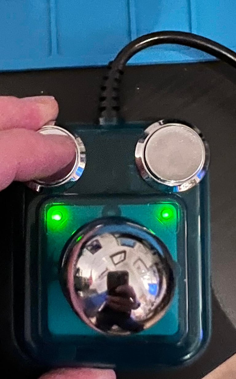
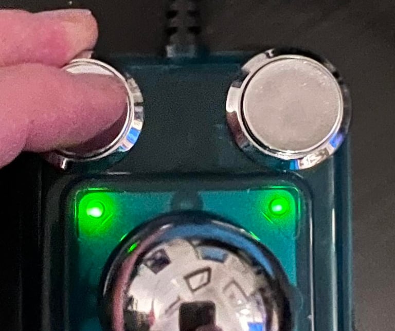
There are two LED also which light up when fire buttons are pressed. Just a fancy effect I guess...
Final result
"A picture worth a thousand words"
Below is a collection of the final result from the refurbishment of this Competition Pro Mini joystick. Hope you like it! Click to enlarge!


Banner picture credits: Aukro.cz