

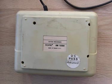
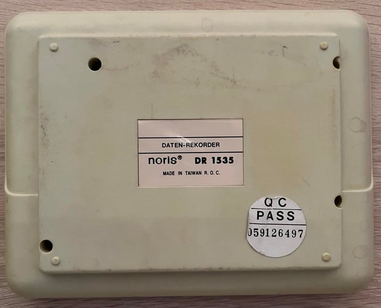
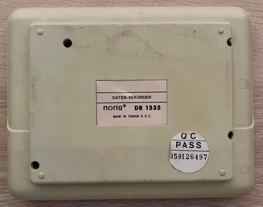
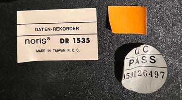
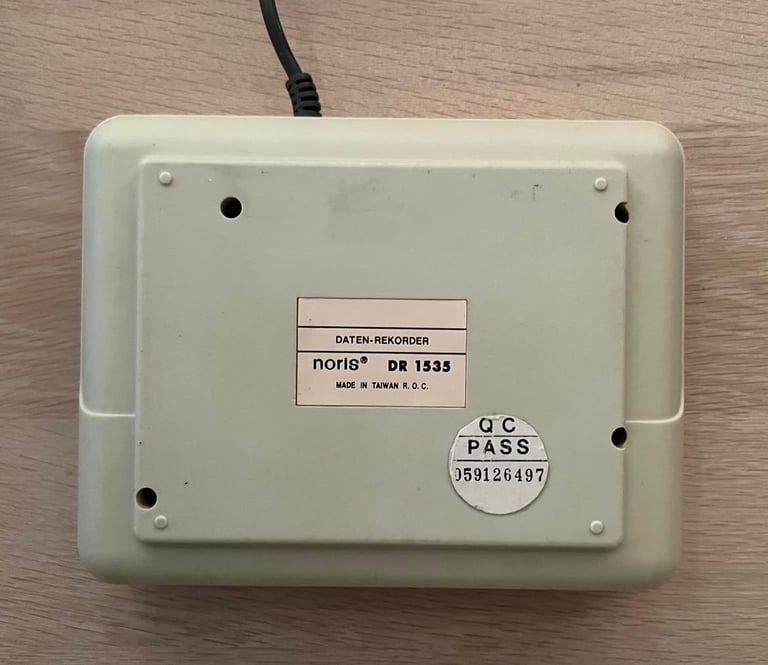
Datenrekorder (DR 1535)
Ser. No. 059126497
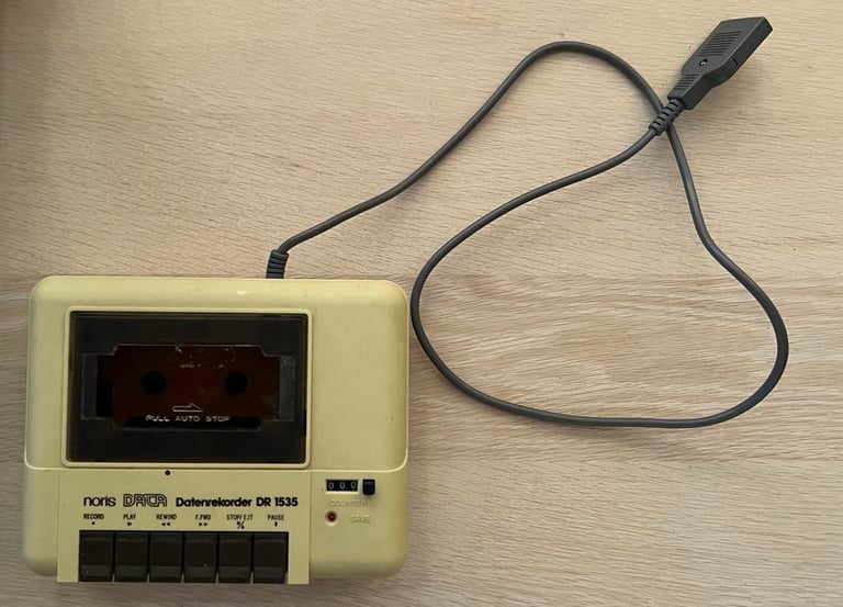
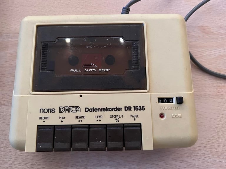
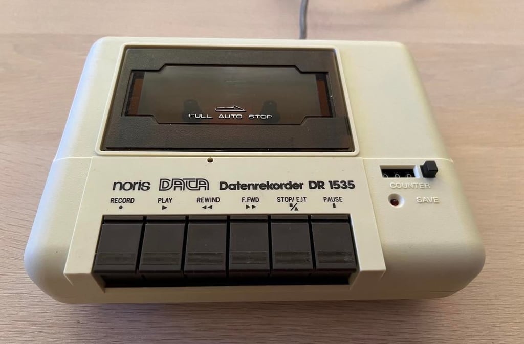
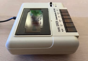
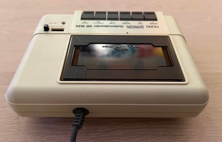
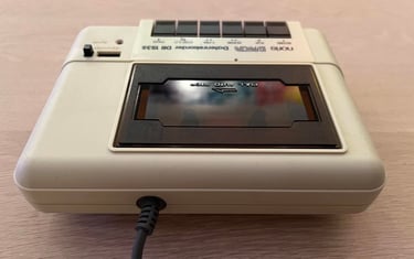
Starting point
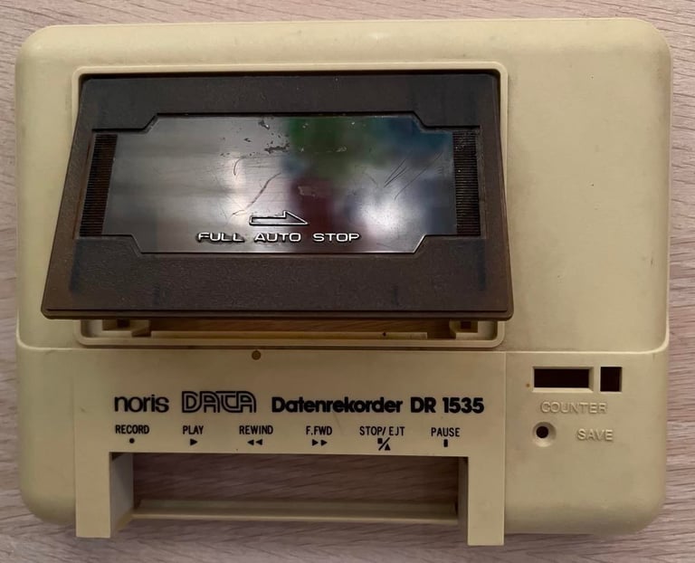
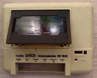
I think that this Noris Data Datenrekorder has a very good starting point. Whether it works or not I don´t know - but it looks to be undamaged and in general good condition. It is quite dirty and yellow, but looks otherwise fine.


Refurbishment plan
This is the first time I refurbish a Datenrekorder. I believe that it is quite similar to the Commodore 1530 C2N Datasette so the plan is to do this trough the following steps:
- Clean and remove stains from exterior casing
- Clean the interior mechanics
- Check cable
- Replace motor- and counter belts
- Check PCB for corrosion and replace old electrolytic capacitors
- Adjust head for optimal tape reading
- Verify datasette operation by testing
Note that several of these steps are done in parallell.
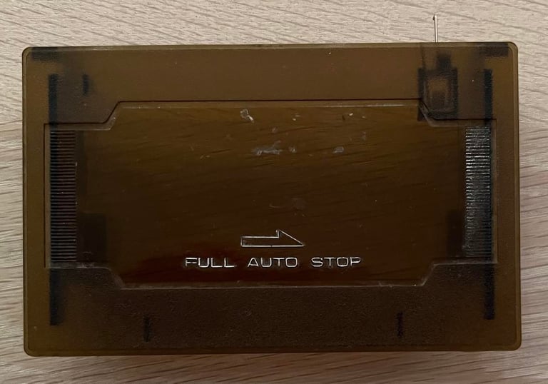
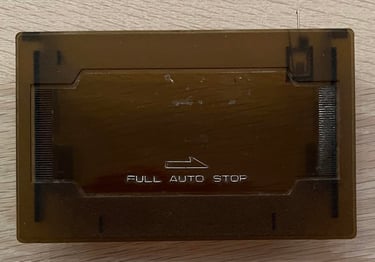
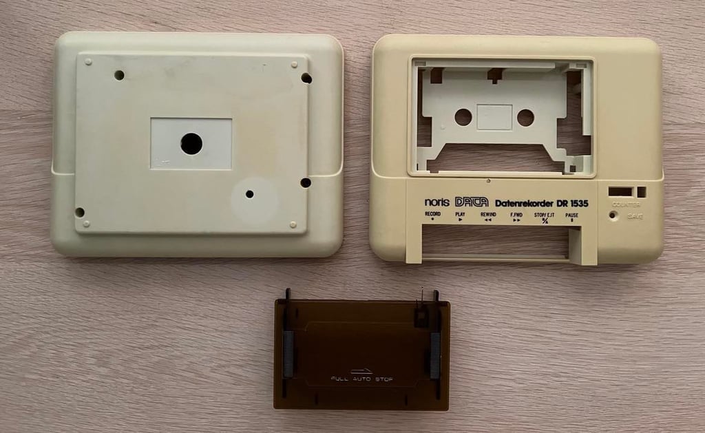
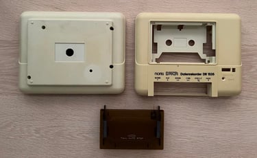
Exterior casing
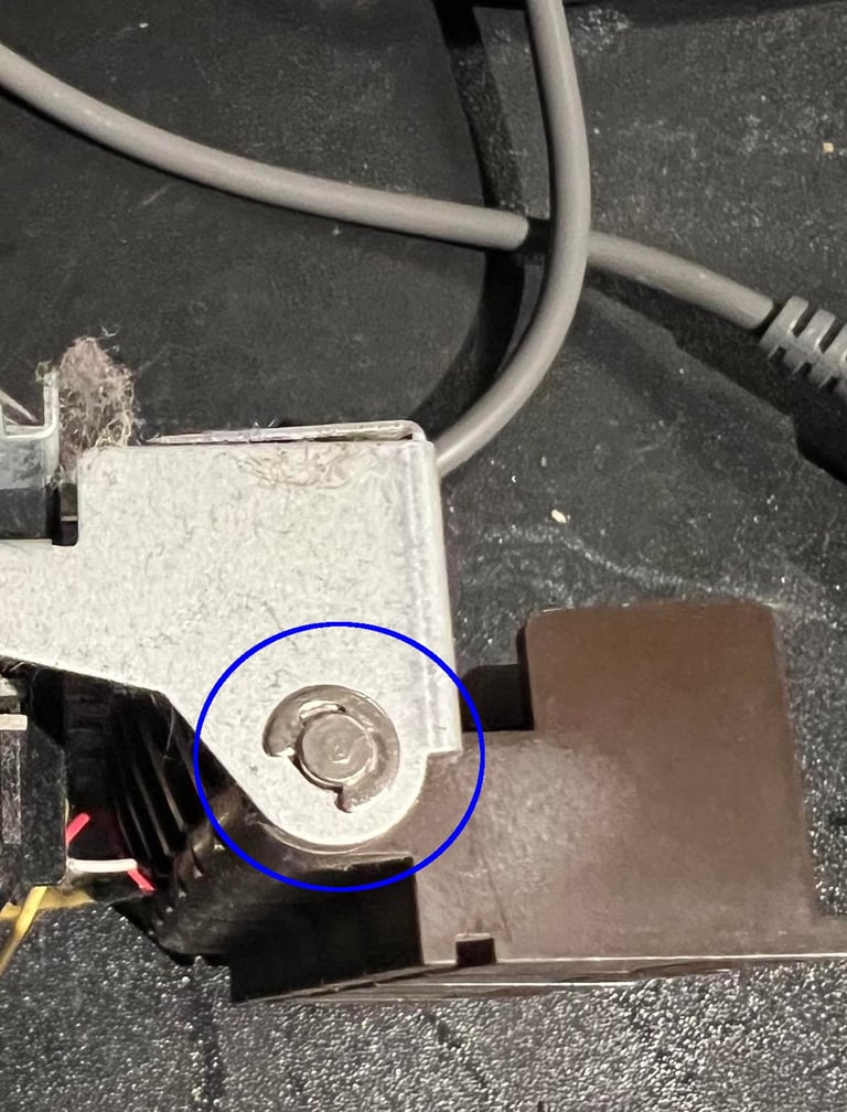
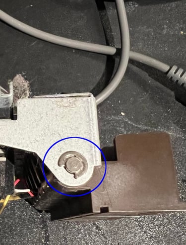
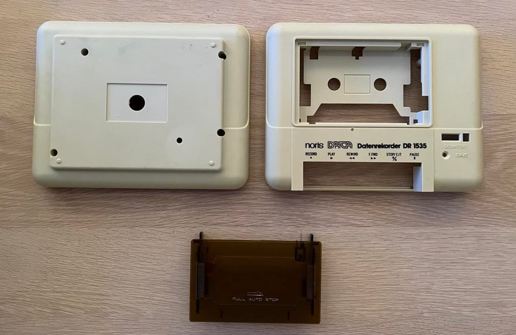
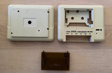
The casing consists of a top- and bottom cover. To separate these the four screws at the bottom are removed. Below are pictures of the top- and bottom cover before cleaning. To get the interior chassis out of the top cover a small screw has to be removed - see picture below for the position of this screw (blue circle).
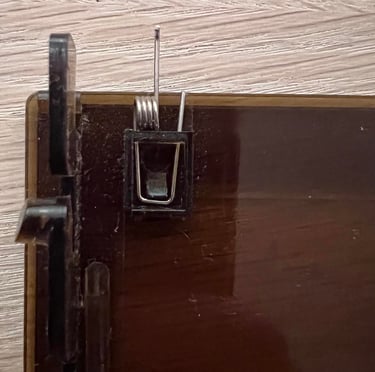
The top lid is easily removed by gently pushing the two plastic brackets towards the centre from below. The tape lid will then pop out - no screws holding it in place. BUT, note that there is a small spring in the top of the lid. Take care not to loose this.

Before the plastic parts are cleaned with water/soap, isopropanol and baking soda all the stickers are removed. This is done by carefully applying some hot air (from a hair dryer) and lifting the stickers with a sharp knife.

The result of the cleaning is shown below. All of the grease is gone. There are some small marks which doesn´t come off (even with baking soda), but it is marginal. But I think this Datenrekoder needs some retrobrighting later.
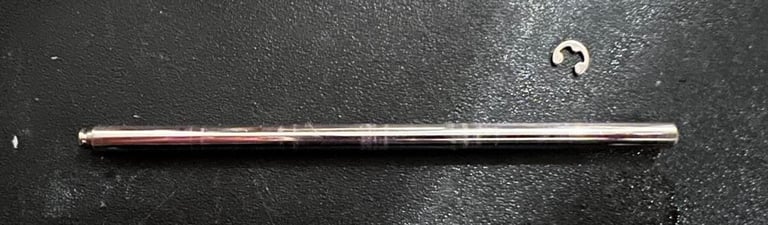
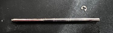
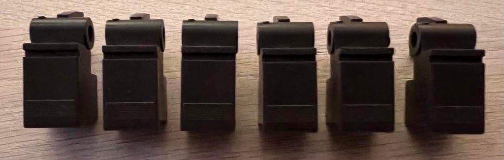
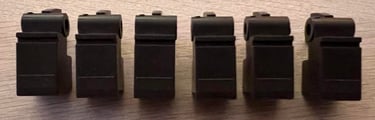
All keys are also cleaned thoroughly. To remove the keys from the interior chassis a small metal clip must be removed first. See picture below for the position of this clip (blue circle). With the clip out of the way the shaft can be removed and all the keys come loose.
The keys are cleaned with mild soap and luke warm water for some hours. They look almost like new.
Since the top- and bottom cover was quite yellowed I decided to retrobright these. This was done by using 12 % Hydroperoxide cream. The cream is replenished about every hour for 8 hours. Also, the top- and bottom cover is wrapped in clingfilm and placed in a box with UV-lamp.
Interior mechanics
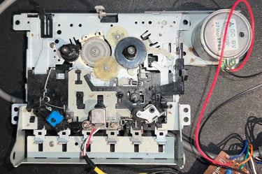
The interior chassis is very - VERY - dirty, but looks otherwise to be intact. There is dust and grease all over, but it seems like there is no serious corrosion, and also all parts looks undamaged.
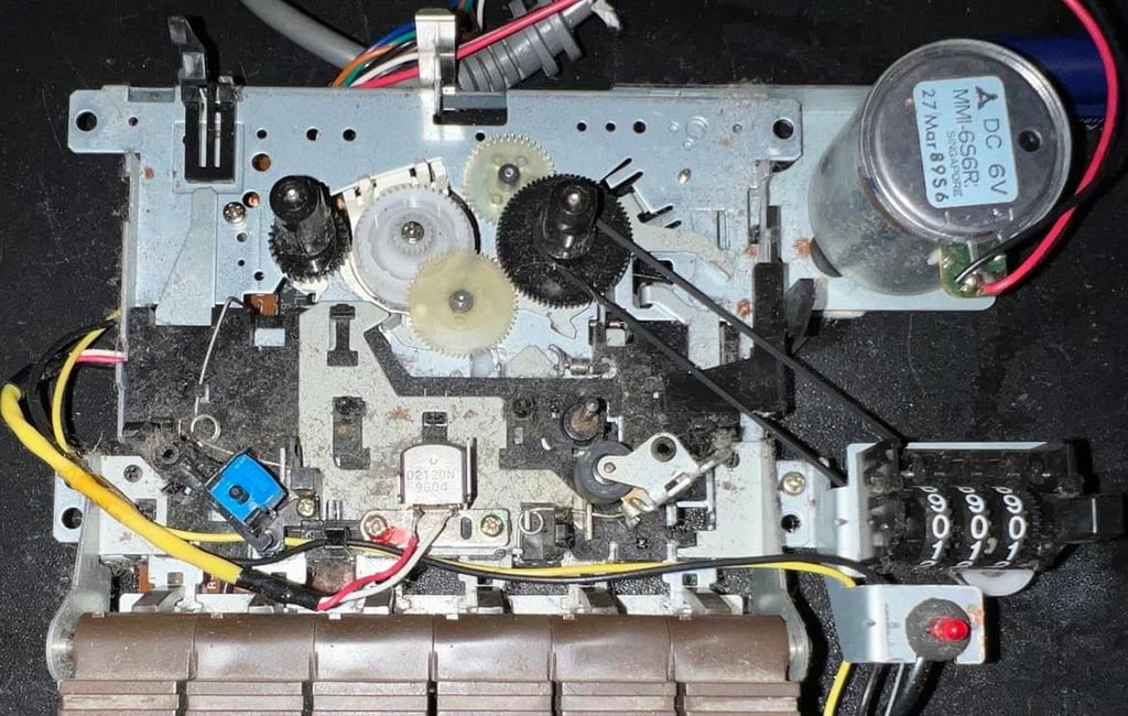


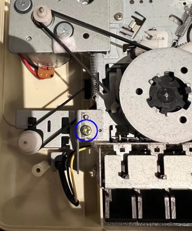
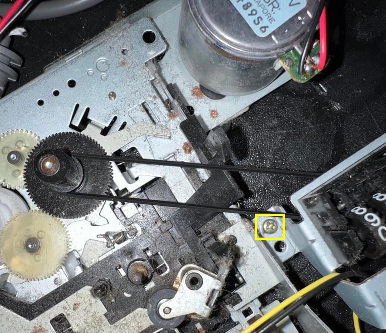
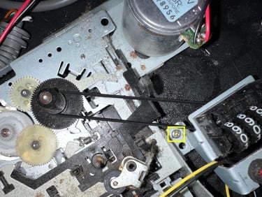
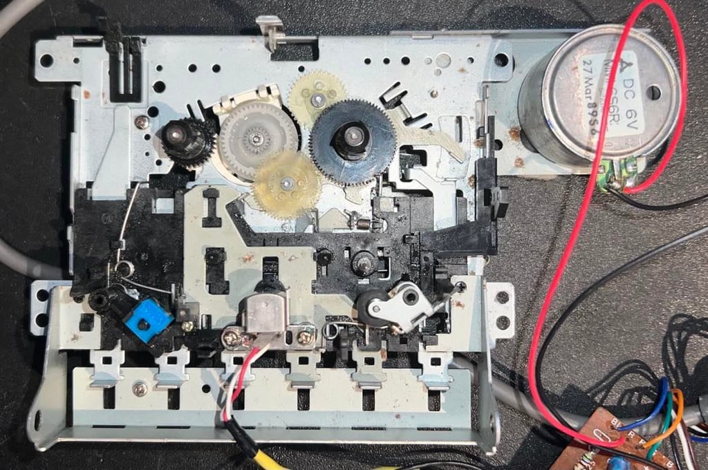
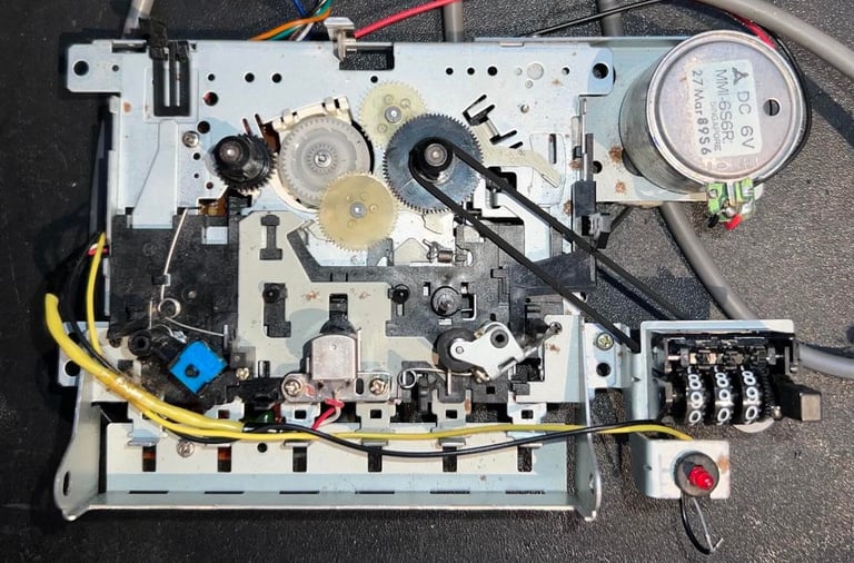
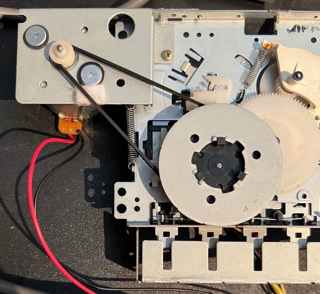
First, the two belts are removed; the one for the motor and flywheel and one for the counter. These are very easy to remove - no screws need to be removed. Just lifting both the belts out of the way. Then the screw holding the counter is removed (this is probably not strictly necessary, but it makes cleaning easier). Below is a picture of the counter belt and the yellow square shows the position of the counter screw.
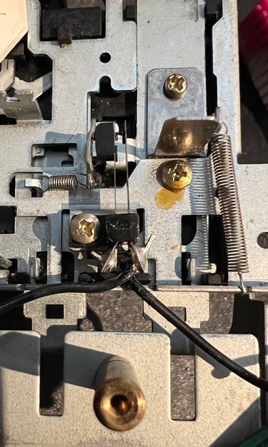
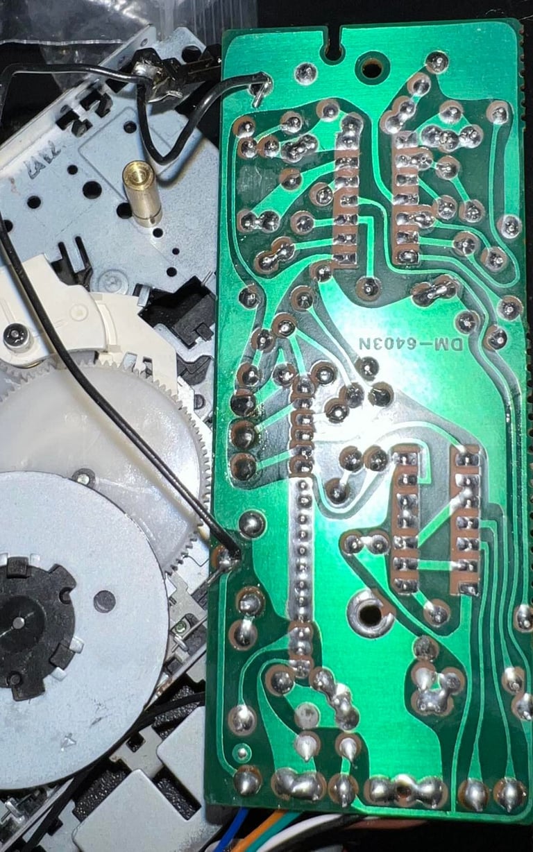
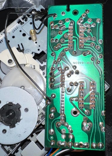
Next the PCB is removed by unscrewing the two screws holding it in place. By carefully lifting the PCB the leaf switch below is revealed. This switch is removed also by unscrewing the little screw holding it in place. When I do this the small plastic bracket holding the switch breaks (or a small part of it breaks of). This is unfortunate, but should not be a big deal. The leaf switch is so light - so no real force is placed upon this plastic bracket - that with some super glue on the screw should do the trick. Picture to the left below shows the leaf switch. Picture to the right shows the PCB after removal.
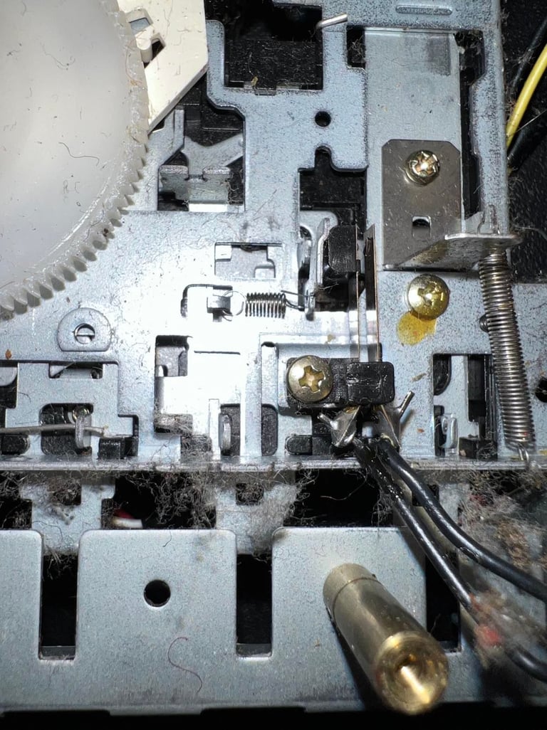

The interior is cleaned throughly with isopropanol and Q-tip. Most of the dust and grease are removed. Note that the erase head, R/W head, pinch roller and capstan will be cleaned separately later (when the belts are back in place). Picture below shows the interior after cleaning.
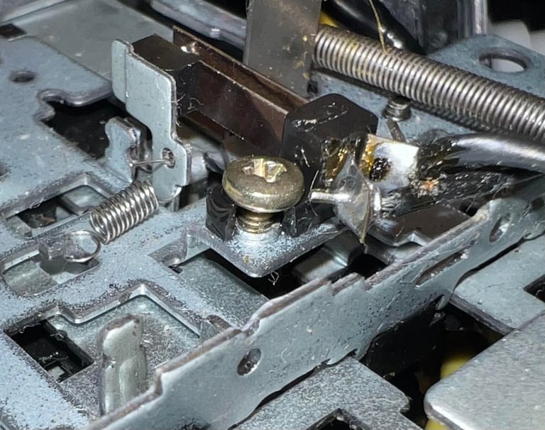
The leaf switch is cleaned with contact cleaner and fastened again. Note that part of the plastic bracket holding the screw broke... but I don´t think it matters much. I used some super glue between the screw and the plastic bracket. As previously mentioned there are no large force pushing this bracket (the force is on the leaf switch) so I think that this fix should do the job. Pictures below shows the cleaned switch and the glued bracket.


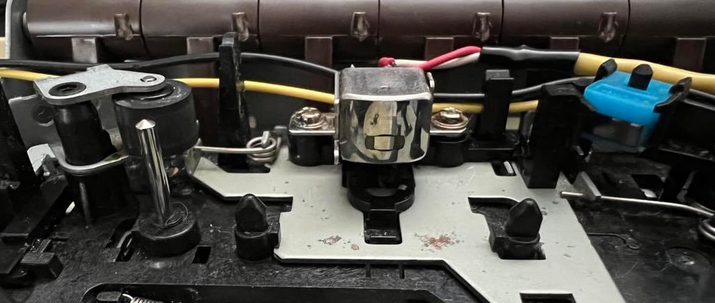
Final part of the cleaning, but probably the most important, is done after the new belts are in place. To get a real good cleaning of the erase head, the R/W head, the pinch roller and the capstan I´ve found out that to clean these while the datasette is running is very efficient. So I connect the datasette to a C64 and then press the keys such as PLAY, FF and REW and then clean all rotating parts.
In the picture below - far left: the capstan (metal rod) and pinch roller (rubber wheel), center: R/W head and far right: erase head.

If you want to see how this simple cleaning of the capstan and pinch roller is done I´ve made two small videos previously (not this datasette). See links below.


Cable
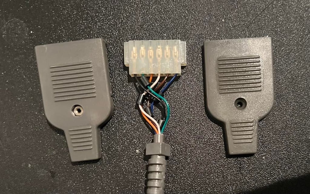
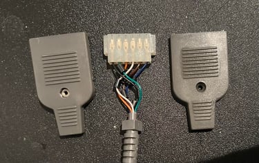
The cable and connector looks to be in good condition. Nevertheless, I will open it and check it - and clean all contacts with contact cleaner spray. Also, this datasette does not have the typical ground wire found on original Commodore datasettes (which makes sense since the ground wire is just meaningless in a Commodore 64 context). Picture below shows the connector after cleaning and checking.
Replacing the belts
In order for the datasette (or Datenrekoder) to operate as it should it is crucial that the belts are not worn out. And after 30-40 they probably are... So these needs to be changed.
Compared to the 1530 C2N Datasette removing the belts in the Datenrekoder is a walk in the park. No need to remove any screws or anything - just lift them off the flywheel and gears. But I notice that the belts in the Datenrekorder are different from the 1530 C2N Datasette.
So I reach out for the experts - DataServe Retro - to see if I can order som belts from them. This is not standard belts in the DataServe Retro shop, but I get help! Something I learn is that it is quite hard to get a proper measurement of a belt. Since I am going to change the belts anyway I decide to cut one of the belts to get a good measurement.
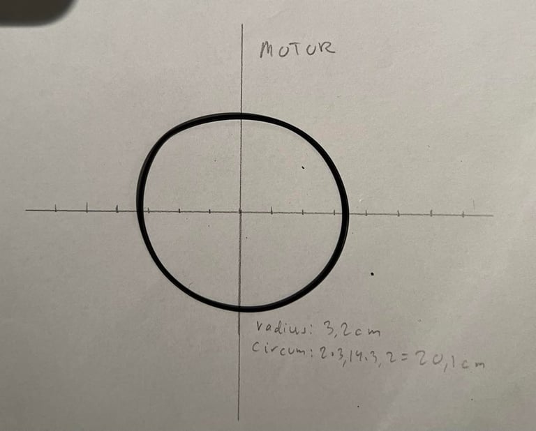
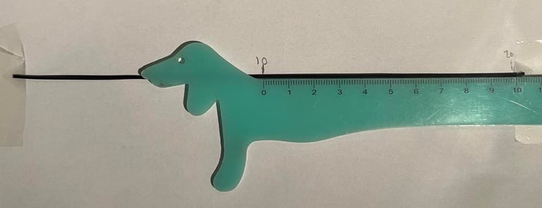

The diameter of this 30 year old belt is about 64 mm. We (DataServe and I) agree on trying to order a 62 mm which is a bit tighter, but then we allow for the slack which has occurred during the years. Fingers crossed!
Also, it turns out both the counter- and motor belt have the same diameter (with my "professional" measurement tools). The counter belt looks a bit thinner, but it is really marginal.
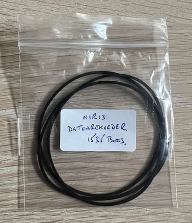
Special thanks to Stephen from DataServe for helping me find a good candidate belt for testing! Below is a picture from the packet I received - excited to see if we can make it work!

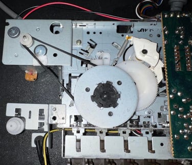
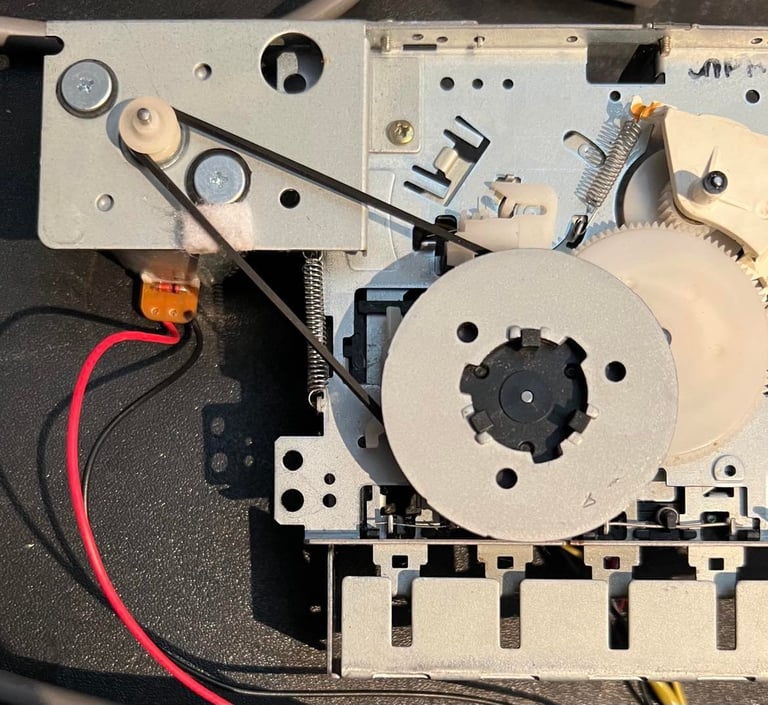
Just as easy as removing the belts it to replace them. Both the motor- and the counter belt is very simple to install. It is just to put them between the cogs and counter, and between the flywheel and the motor. They feel very good! Not too tight and not too loose! I think this was a good candidate! Picture below shows the new belts in place. Note that the counter is also put back in place.
PCB and electrolytic capacitors
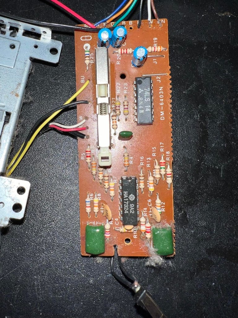
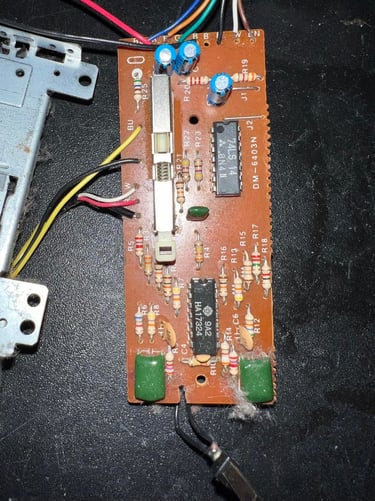
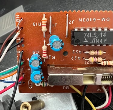
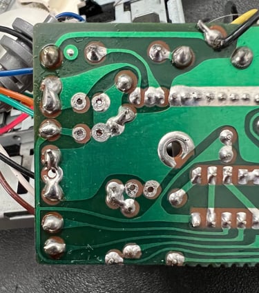
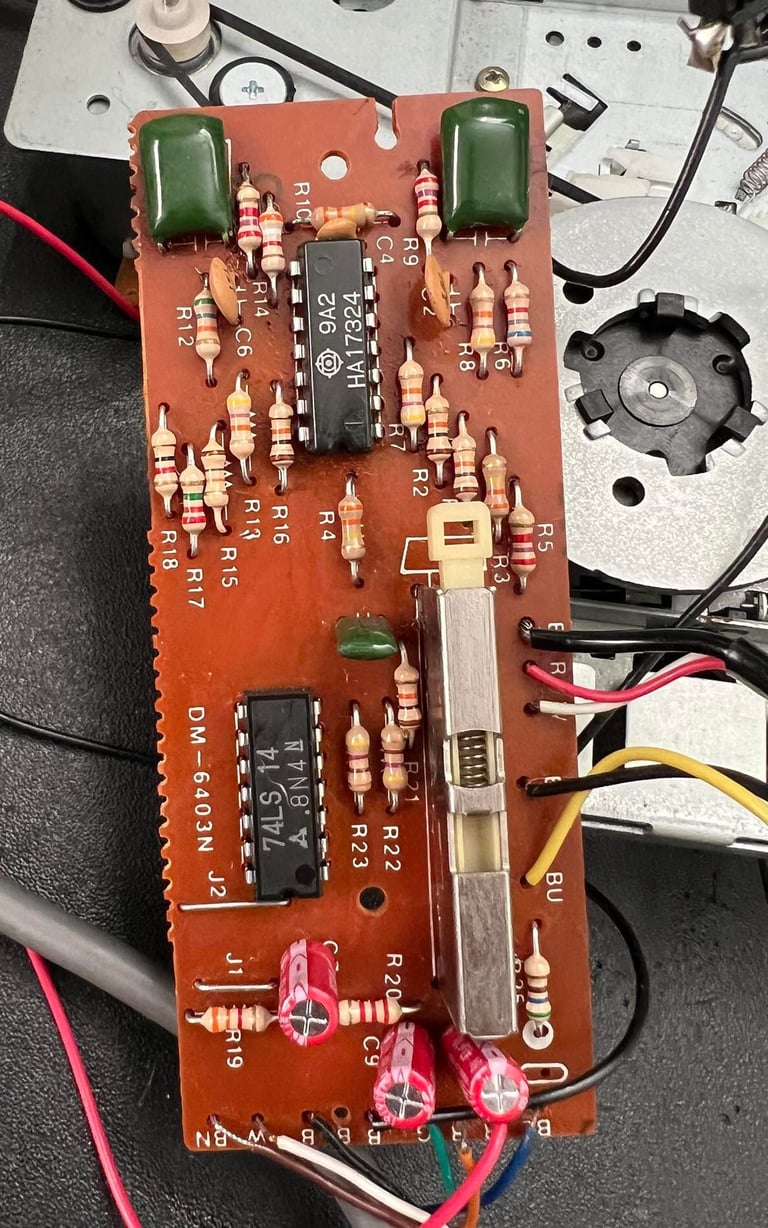
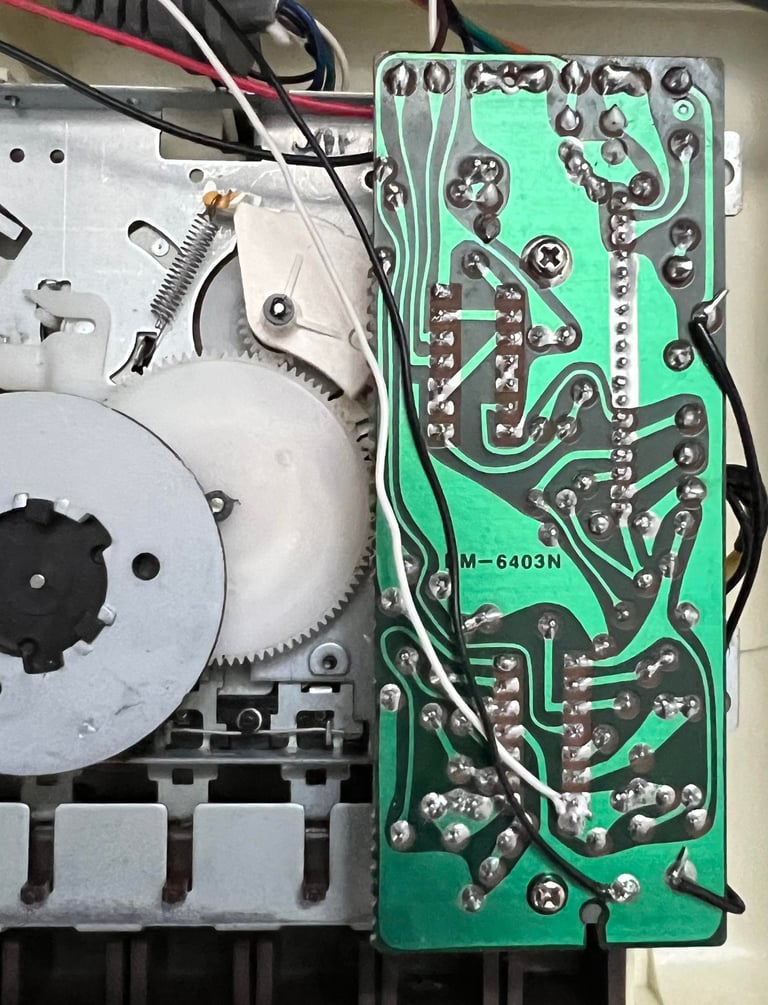
Beside from being a bit dirty the PCB looks good. I can not see any corrosion and all chips and capacitors looks undamaged / no leaking. The PCB is thoroughly cleaned with isopropanol and Q-tip. The PCB is marked with "DM-6403N" and the OP-Amp IC is HA17324 from Hitachi. I will use this information later when controlling and adjusting the R/W head.
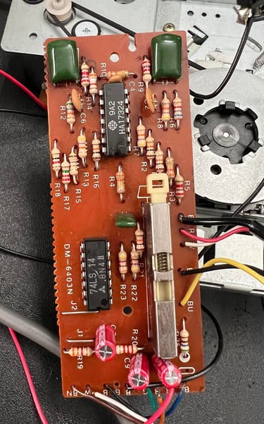
The three electrolytic capacitors are replaced since these can dry out due to old ag so I think it is good practice to replace these. The capacitors are all 47 uF [16V], and are replaced with Wurth Electronics capacitors with the same capacitance and voltage rating. Pictures below shows the old electrolytic capacitors and after they have been desoldered.

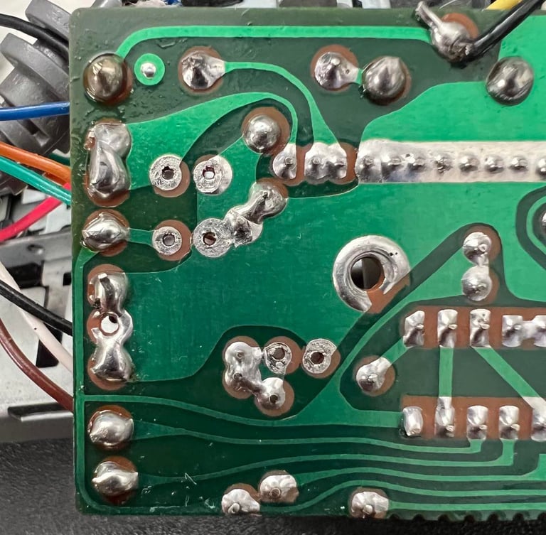
Below are pictures of the PCB with the new capacitors and after cleaning.
R/W head alignment
In addition to a properly working motor belt it is crucial that the read- and write head is aligned to the magnetic tape for the datasette to load tapes correctly. Back in the 80´s it was not uncommon that datasette owners grabbed their small screwdriver and tried to adjust the R/W head in order to make the cassettes load... but this was often done completely in the blind.
Over the years I´ve found a good way of doing this by using tools such as an oscilloscope connected to the 2nd OP Amp stage in the datasette and software running on the Commodore 64. For a thorough description on how I do this I recommend reading my "HOWTO" article for details.
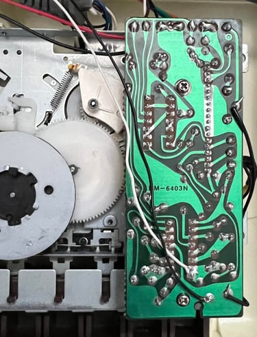
Two wires are temporarily soldered to the PCB. The white wire is connected to the output of the 2nd OP-Amp stage and the black is connected to ground. These two wires are later connected to the oscilloscope. The wires are fed trough the back together with the rest of the cable, and the complete datasette is re-assembled.
Note that it is very important to re-assemble the whole datasette before adjusting and verifying. The datasette should be "as-is" to make sure that the R/W head is aligned to the real position of the cassette in the tape lid. Picture below shows the datasette during checking and adjusting.
Note that it is very important to re-assemble the whole datasette before adjusting and verifying. The datasette should be "as-is" to make sure that the R/W head is aligned to the real position of the cassette in the tape lid. Picture below shows the datasette during checking and adjusting.
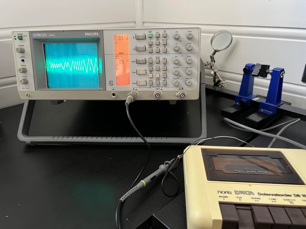

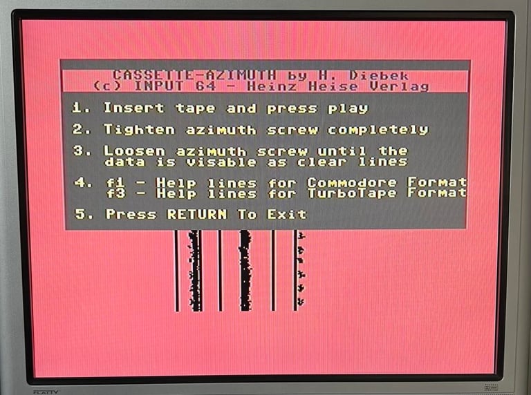
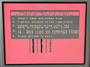
I notice that the signal amplitude is actually quite good - before any adjustment to the R/W screw. I try a few tapes and they load without any issues, so I choose to wait with the adjustment of the small screw. It is easy to adjust the screw, but I will not do it unless I need to. So next step is to run the cassette-azimuth software on a Commodore 64 while running av tape. The aim is to have the three lines as vertical as possible. And the result is very promising - see picture below. So I decide to leave it like this and wait for the final testing. If the final testing fails I will go back to this stage and try to adjust it.
Testing
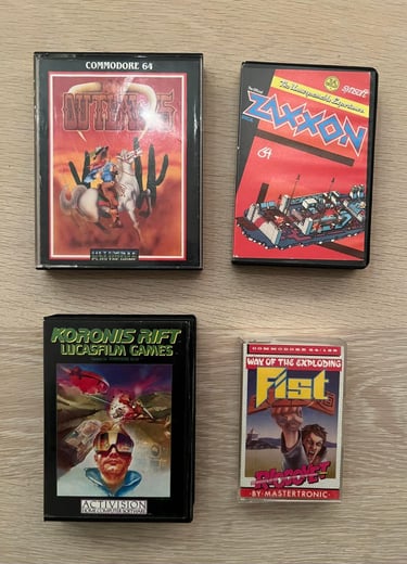
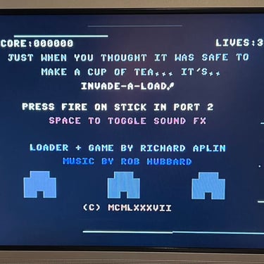
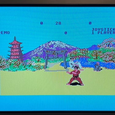
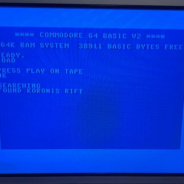
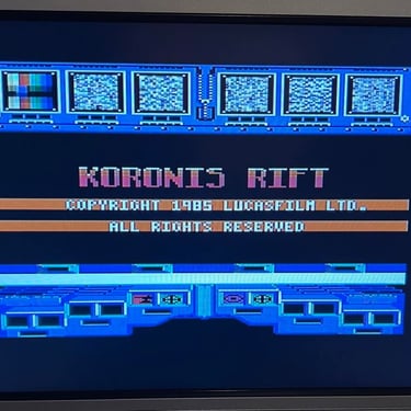
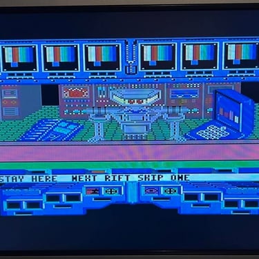
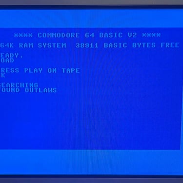
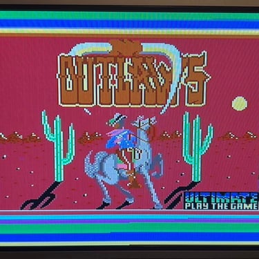
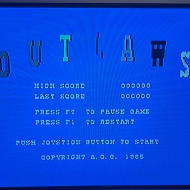
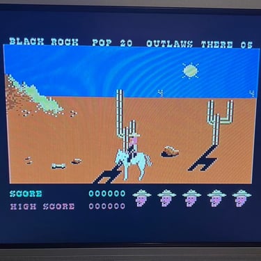
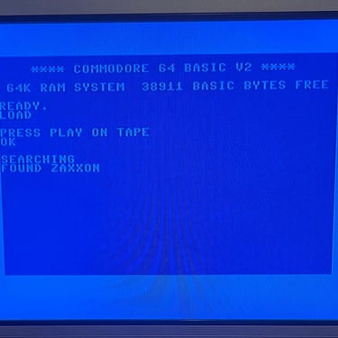
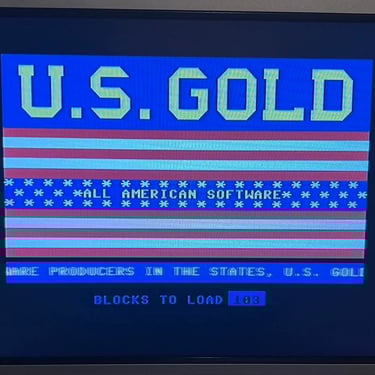
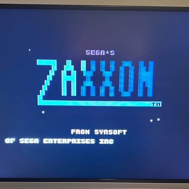
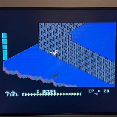
To verify that the datasette works as it should I select I choose four games on tapes that I do know work - but they are original and old. This means that the tapes are recorded professionally (with a proper aligned R/W head) and since they are old the magnetic coating on the tape is worn - which makes it a bit harder to read. Picture of the tapes selected are shown below.

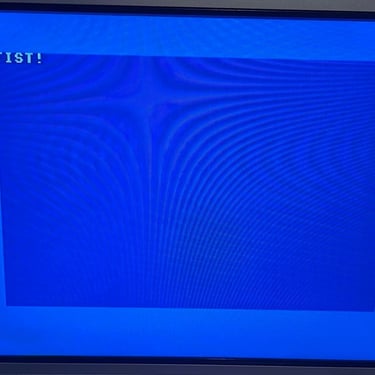
All of these games load without any issues so I conclude that the testing was successful. Below is a gallery of pictures from the testing.
Final result
"A picture worth a thousand words"
Below is a collection of the final result from the refurbishment of this datenrekorder. Hope you like it! Click to enlarge!


Banner picture credits: VİLDAN-ATİLA GÖKÇEN CALCULATOR & COMPUTER & RETROTECH MUSEUM