

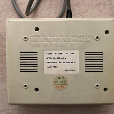
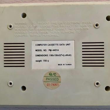
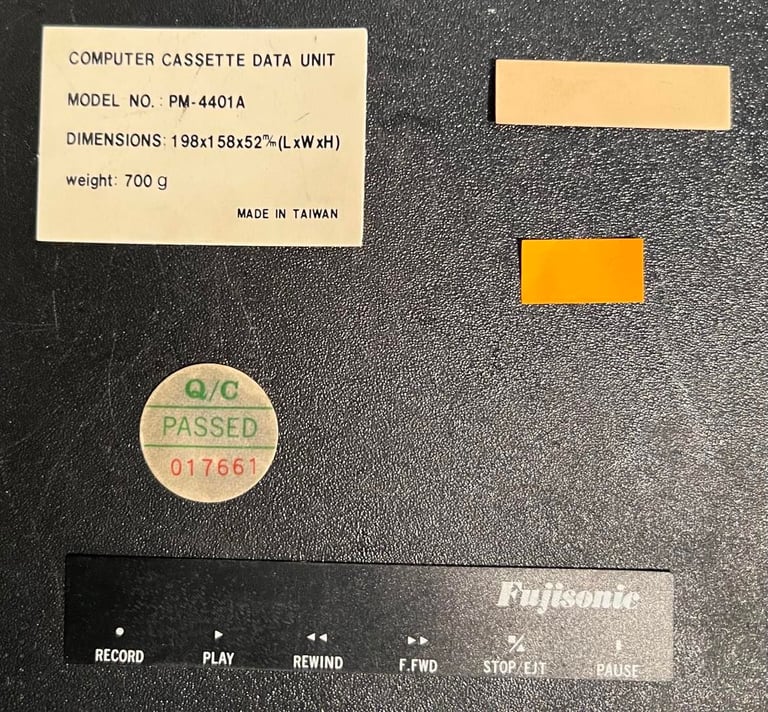
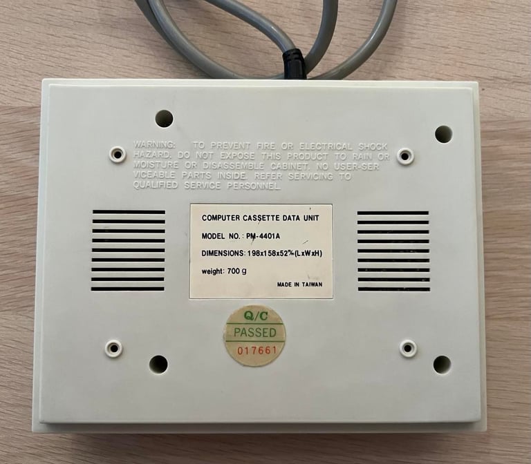
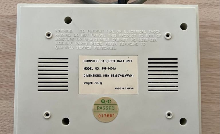
PM-4401A
Ser. No. 017661
Refurbishment plan
To refurbish this datasette the plan is to do this trough the following steps (some of these in parallell):
- Clean and remove stains from exterior chassis
- Retrobright exterior chassis
- Clean the interior mechanics
- Check cable and replace strain relief
- Replace motor- and counter belts
- Check PCB for corrosion and replace old electrolytic capacitors
- Adjust head for optimal tape reading
- Verify datasette operation by testing
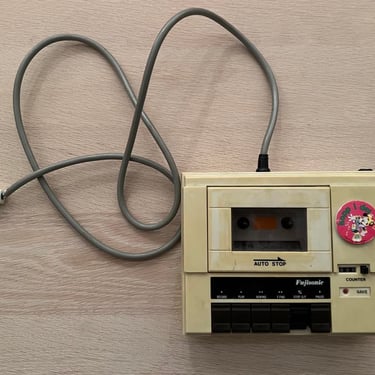
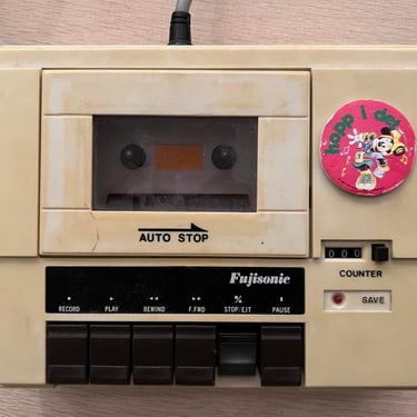
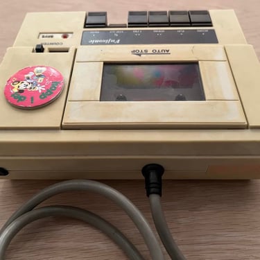
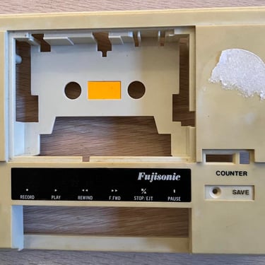
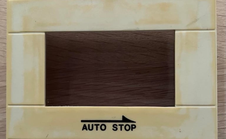
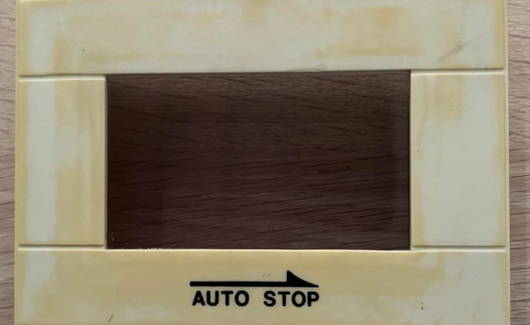
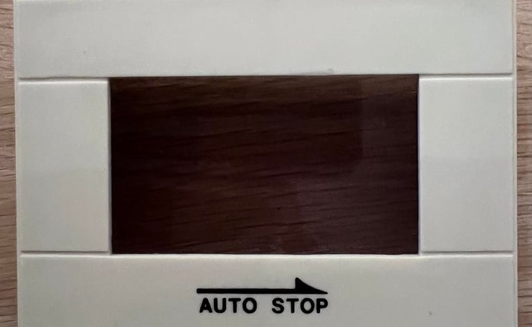
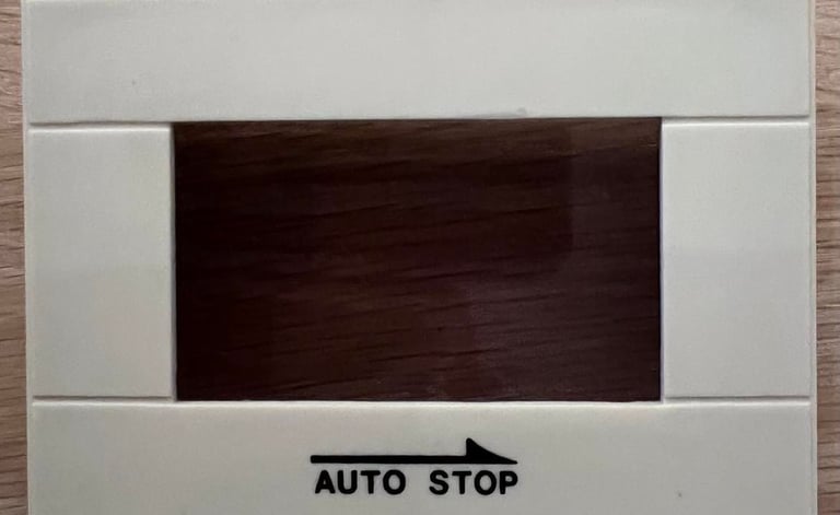
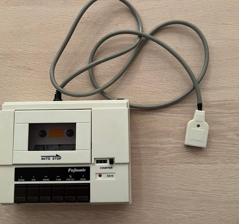
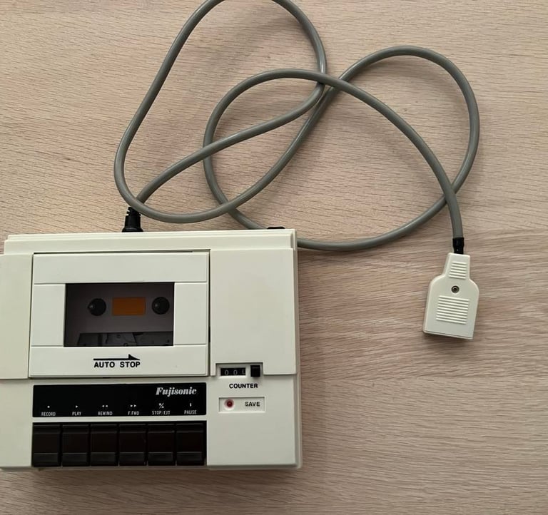
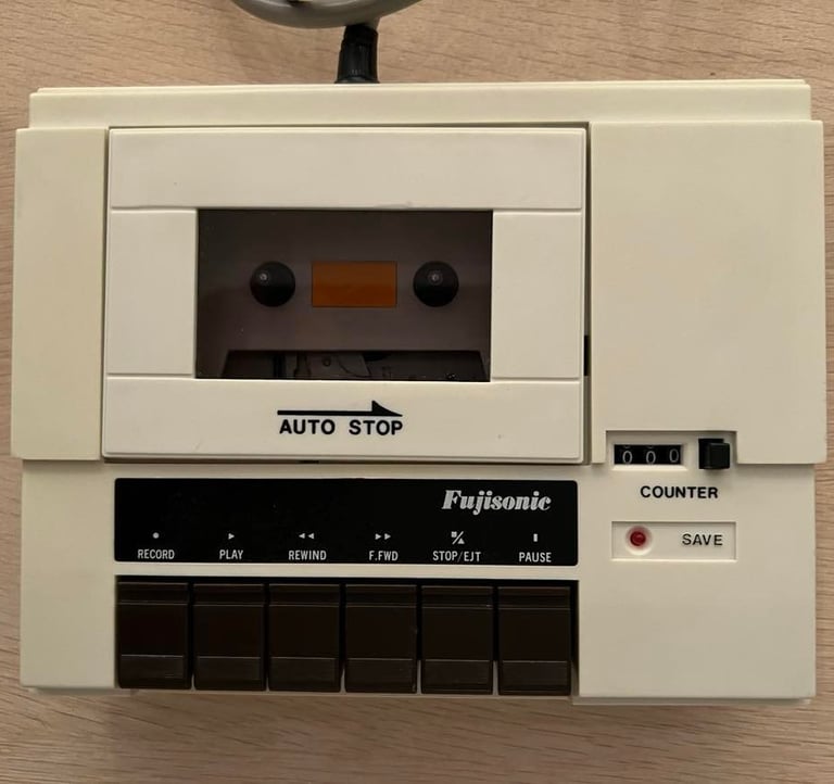
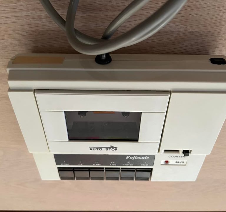
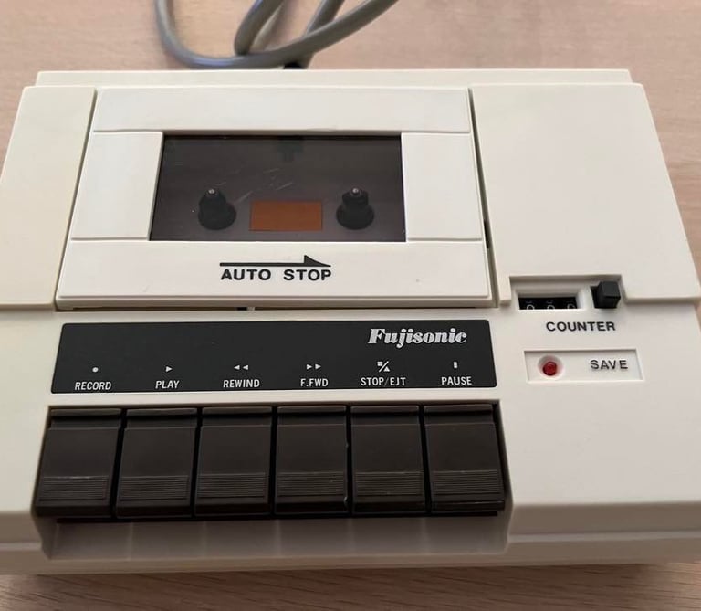
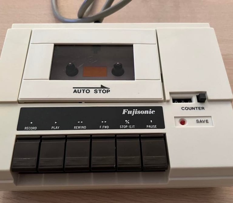
This will be an interesting project! I´ve never seen one of these datasettes before. It is marked "Fujisonic", but I wonder if this is an OEM device which means that it´s produced by one original company and then rebranded with different names. This datasette is in quite poor condition; the STOP button is stuck (?), cable connector needs repair (?), discolored and dirty. And I have no idea if it even works at all - or will work eventually.
Below are some pictures of the datasette before the refurbishment process begins.
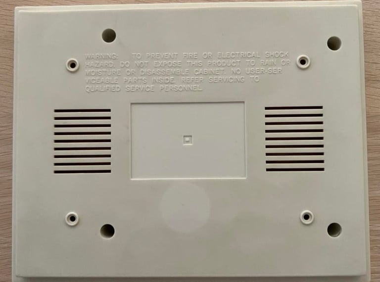
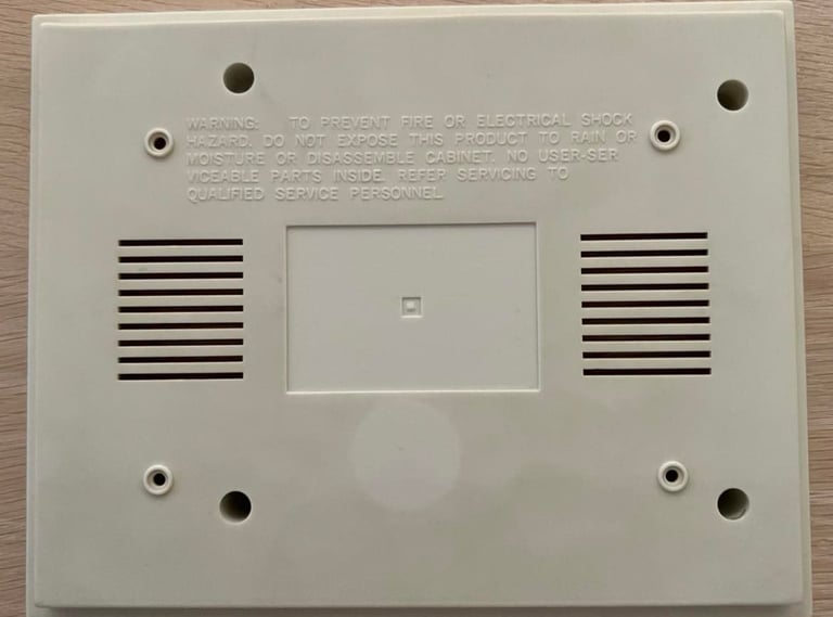
Exterior chassis
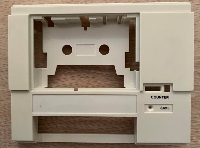
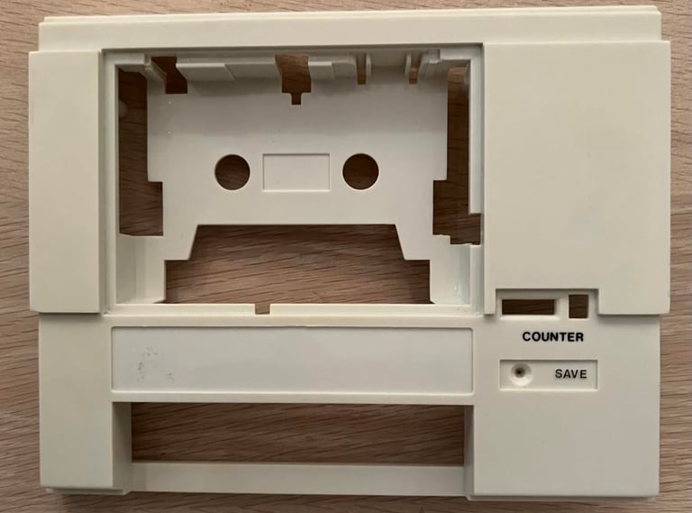
The datasette is disassembled by first removing the four screws at the bottom. This splits the chassis in two parts; top- and bottom cover. These covers are quite dirty, but otherwise looks intact. Also there is a nice little sticker "Hopp i det" which translates literally from Norwegian to English to "Jump in it" - it´s a Norwegian saying which will mean something like "Just do it" in English.
Below are some pictures of the disassembled parts before cleaning (the "Hopp i det" sticker is removed).
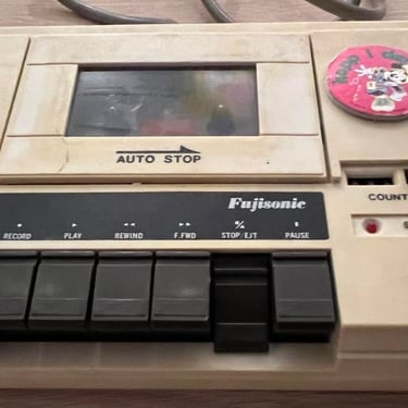
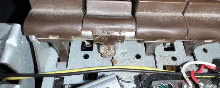
The disassembly reveals that the "STOP" button is not stuck. It´s broken unfortunately.
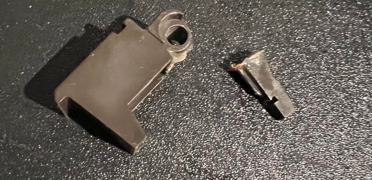
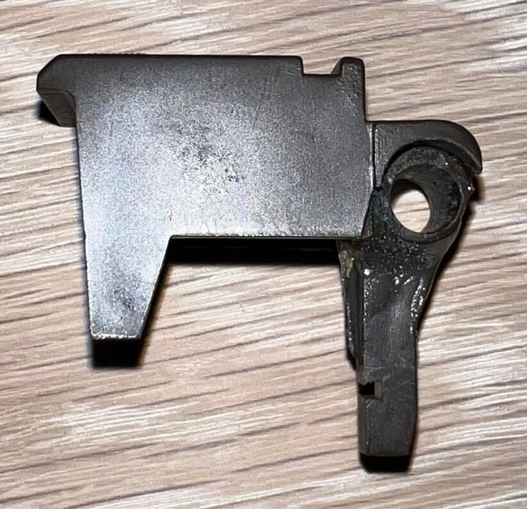
Not quite sure how to fix the broken key, so I ask the Facebook forum "Commodore/Amiga Norge(Norway)" on advice. And I get feedback to try a good 2-component glue or superglue. I try the 2-component glue from Loctite and let the glue harden for a week. I´m not sure if this work at the final testing - but I´m willing to give a try. The picture to the left below show the broken key, and to the right is the key after being glued and left for a week.
Before I start the cleaning process I make sure:
All stickers are removed to avoid these are damaged from liquids
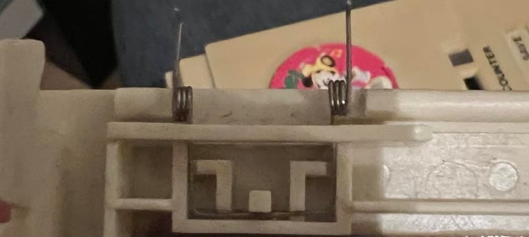
The little spring which is part of the tape lid is removed and stored in a safe place
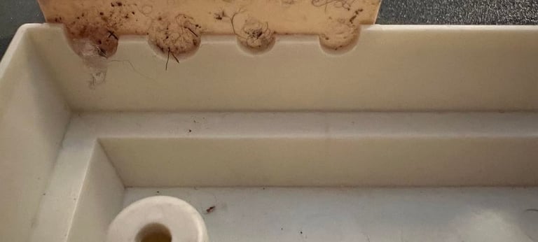
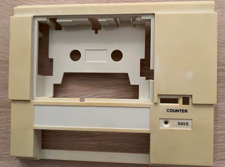
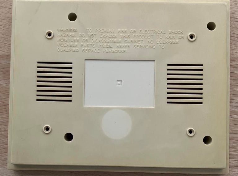
The pictures below show the stickers removed, the sticker hiding four factory made holes and also where the little spring is located in the tape lid.


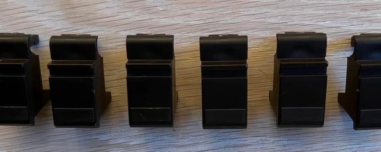
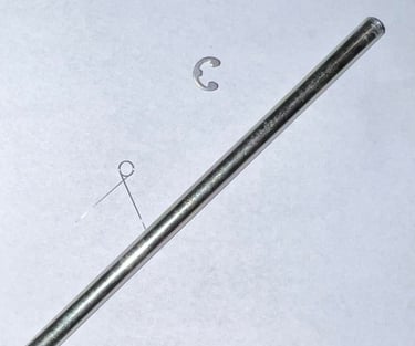
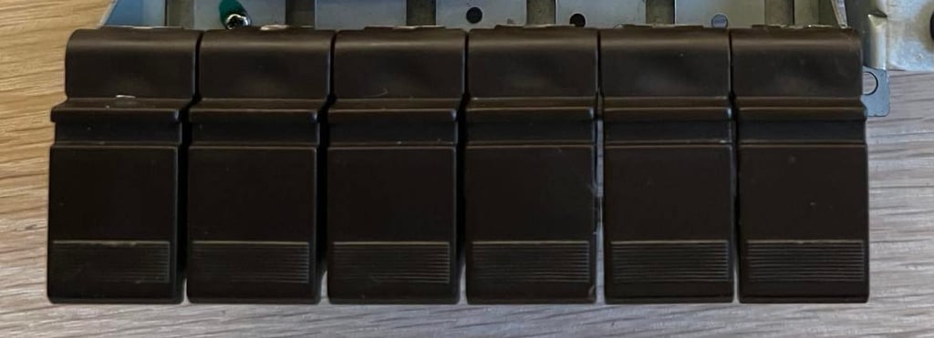
The six keys are disassembled from the chassis also. This is done by first removing the small clip on the right side of the keys, and then pulling the shaft from the left. With all the keys loose they are cleaned with mild soap water, isopropanol and glass spray. Below are pictures of the keys after cleaning and also of the shaft and the little clip. Note that there is also one little spring here. These small springs are used at the bottom of the keys and give a small "push" towards the chassis. In this datasette one of these springs are missing unfortunately. Nevertheless, the force in these springs are quite low so I don´t expect to matter very much with this missing spring.

After a week or so I assemble the keys to the shaft. I have to sand a bit in the hole of the glued key to get the shaft to move smoothly (there are some glue residue preventing this). Also, I do a little change: all keys are identical so I use this glued key as "PAUSE" key instead of "STOP" key. The reason for this is that I think that the PAUSE mechanics are quite "low force" in regards of how much force you need to apply in order for it to work, and also "who use a pause key on a datasette for Commodore"? So this key will hopefully work, but be used quite infrequently. Below is a picture of the assembled key (with the repaired to the far right).

The exterior chassis looks better after the cleaning (see pictures below). But it´s still very yellow! Notice the difference in color - this needs to be retrobrighted. Although, I am not really sure how retrobrighting will be with such heavy and scattered yellowing.


I think the retrobrigthing was a success! It´s not completely back the original white color, but I think it is very close. Check the pictures below.
Interior mechanics
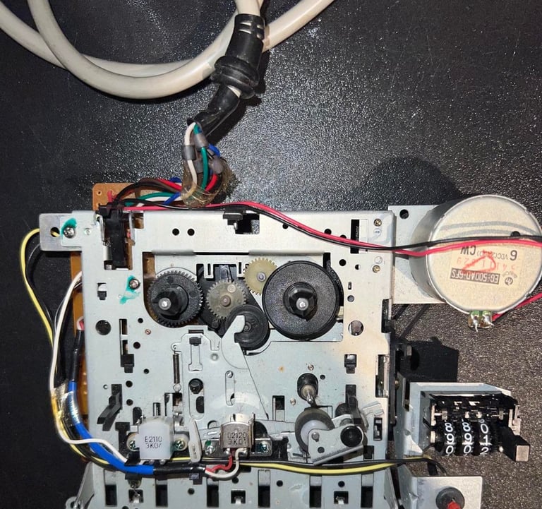
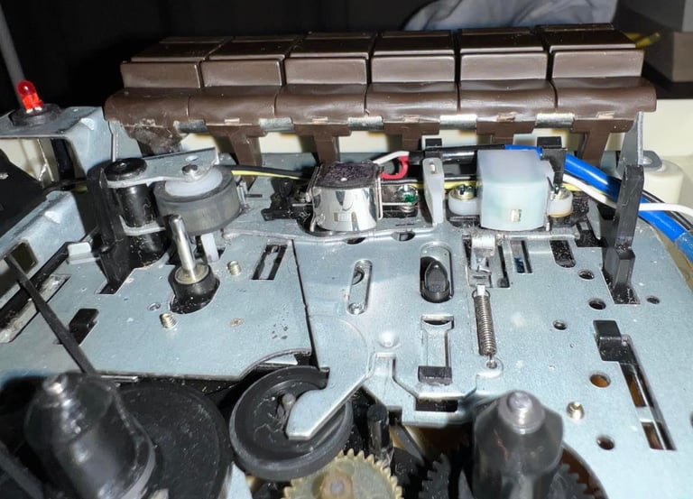
The interior mechanics looks quite nice (see pictures below). I can´t see any immediate damage or problems so I clean this interior properly with a combination of mild soap water and isopropanol. Note: the counter belt was removed when the pictures were taken. The motor belt is also removed when the cleaning is done to make sure all gears are cleaned properly, and these belts are to replaced with new anyway.


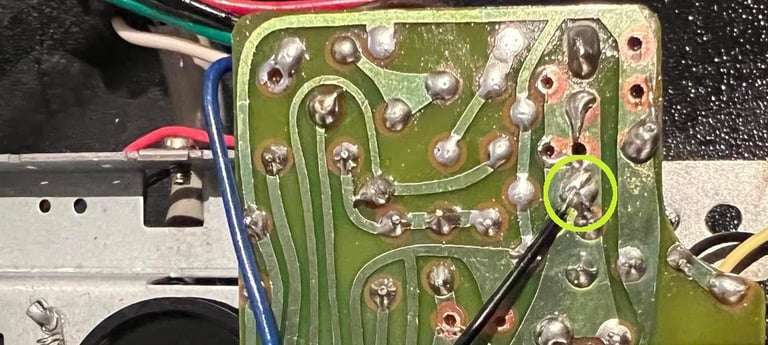
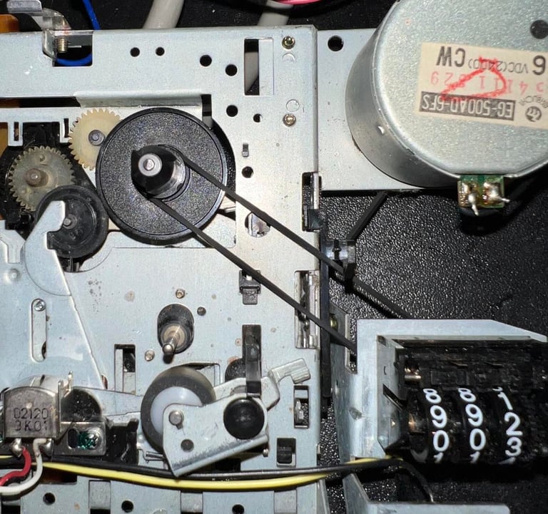
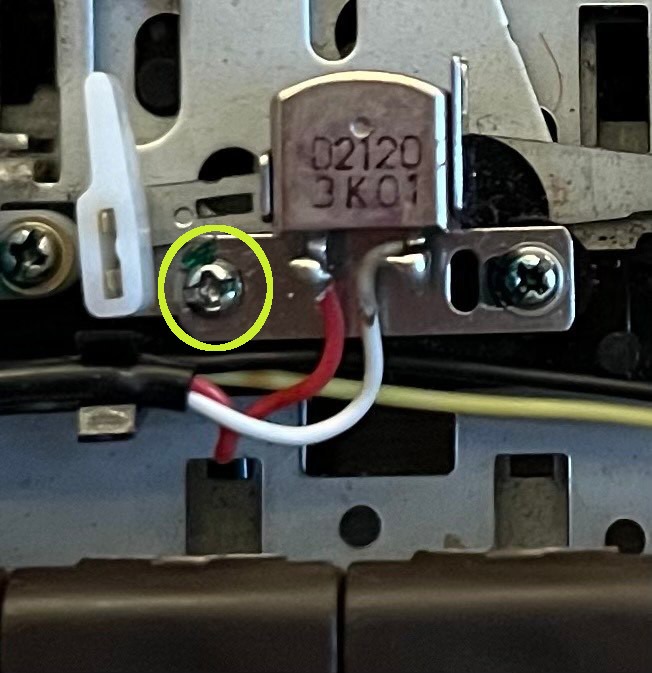
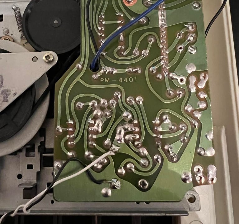
To clean the backside of the interior the PCB is partially removed. This is done by removing the two screws holding it to the chassis. Next is to desolder the black wire which protrudes the little hole of the PCB. Below is a picture describing the point to desolder (yellow circle) (click to enlarge).

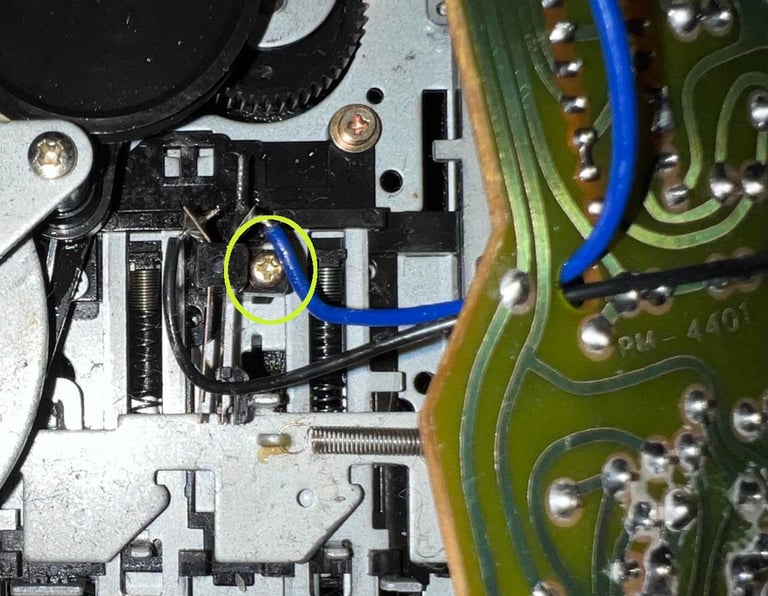
When the PCB is carefully tilted now it will reveal a small switch. Although I don´t think it´s stricly required I choose to remove this switch. It will make cleaning both the interior chassis and the PCB a lot easier, I can verify that the switch have no corrosion and with the PCB out it´s way easier to replace any electrolytic capacitor. Picture below show the small switch and the yellow circle points to the screw which needs to be removed (click to enlarge).
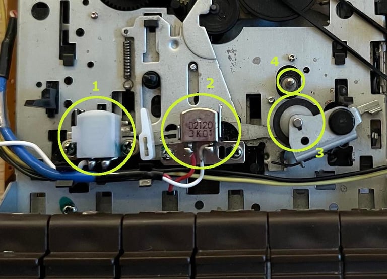
There are some areas which is critical is cleaned properly in order for the datasette to operate optimal:
The erase head [position 1]
The read/write (R/W) head [position 2]
The pinch roller [position 3]
The capstan [position 4]
Below is a picture where these are located in the datasette.
Now, to clean the erase head (1), the R/W head (2) and the capstan (4) I use isopropanol on a Q-tip. For the pinch roller I first use some mild soap water on a Q-tip, and then GENTLY / BARELY rub with some P240 sandpaper just to remove the top layer grease. Afterwards I clean it also with isopropanol. To clean the pinch roller and capstan really good I use a little trick; I connect the datasette to the C64, power on and press keys such as PLAY/FF/REW. This will makes all rotating parts move, and makes the cleaning way easier. It´s very important that the capstan and pinch roller are cleaned. They make sure that the tape is dragged firmly trough the playback. Otherwise the pulling of the tape can slip intermittently and cause "?LOAD ERROR".
I made a short video where I show this (on another datasette). Take a look if you like:
Below is a picture of the cleaned erase head, R/W head, capstan and pinch roller. Notice that on the pinch roller there still are some residue/discoloring from previous tapes. I choose not to clean it further to make sure the rubber is not damaged. As of now, it is clean and refurbed!
The rest of the interior is cleaned with isopropanol. I can´t see any corrosion either so I don´t use vinager on this one. Below are pictures of the top and bottom of the interior chassis after cleaning.
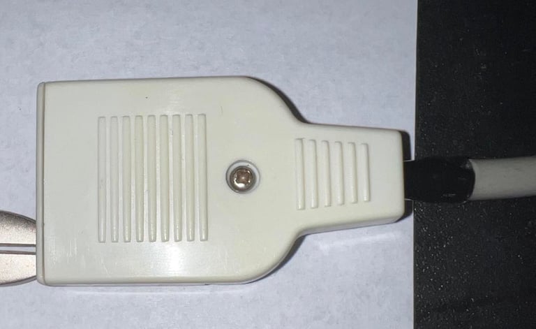
Cable
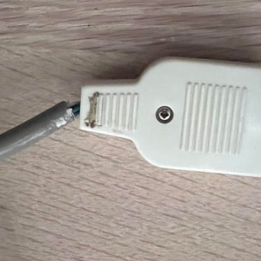
The cable needs some love and tenderness... It doesn´t look broken from the outside, but the strain relief is at least something that needs to be fixed. And it´s quite dirty with plenty of stains.
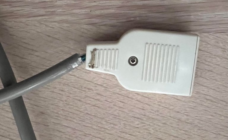
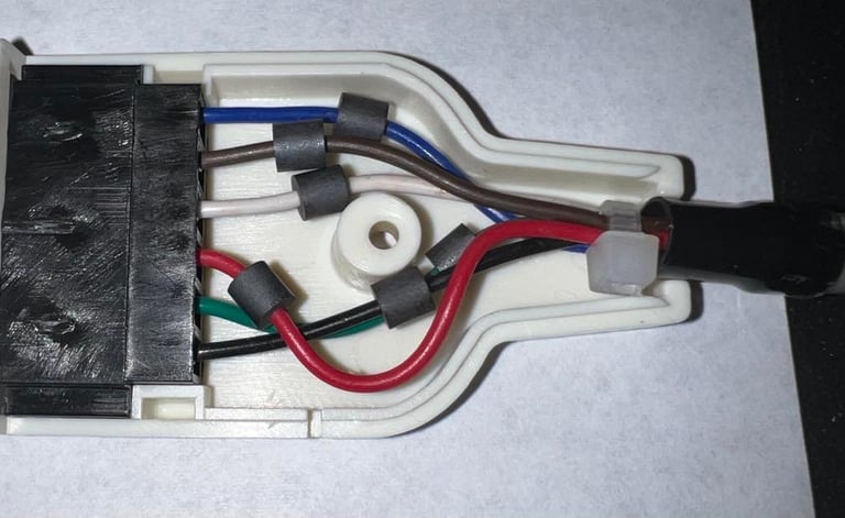
First, the screw and nut is removed. Then the two plastic parts of the contact is cleaned with a combination of mild soap water and isopropanol. The stains are quite tough to remove, but I manage to remove them. Inside the contact is the original strain relief; just a black shrink plastic. To refurbish this I clean the area around the cable end (the insulation) and gently slide the shrink plastic back in place. To make sure it stays in place I use a small cable tie to lock it. The contact itself - the part which goes into the C64 - is cleaned with contact cleaner. Note; the cable cutter in the picture is just to hold the contact down while taking the picture.
Replacing the belts
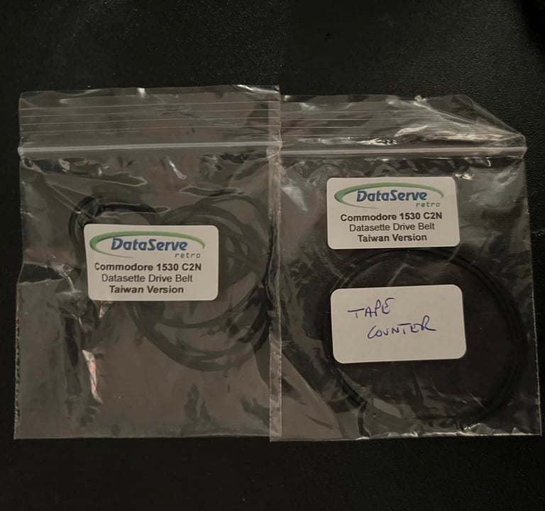
There are two belts in the datasette. One which is used to drive the counter and one between the motor and gears. It´s only the latter which is crucial to replace, but it´s good practice to do both. In fact, my experience is that replacing the belts is THE one thing which should be done in refurbishing a datasette. I think this is more important than adjusting the R/W head actually - but doing both is of course what we aim for!
But what belts to choose? For the 1530 (C2N) datasette from Commodore there are two version; one for the Japanese made and one for the Taiwan made. This datasette is in fact made in Taiwan, but I think that is just a coincidence. Nevertheless, I check the old belts with a new pair for the Commodore Taiwan version and they do match! So I go for the 1530 (Taiwan) belts. The belts I use are ordered from DataServe-Retro.

Replacing the counter belt is very easy. It´s just to remove the old (well, that´s a lie because the old is so weared out it just fell out by itself). And replace with a new fresh belt.

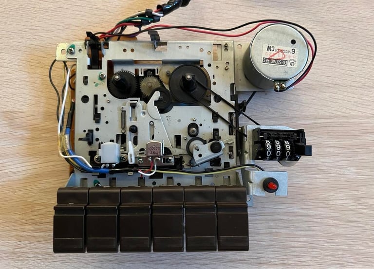
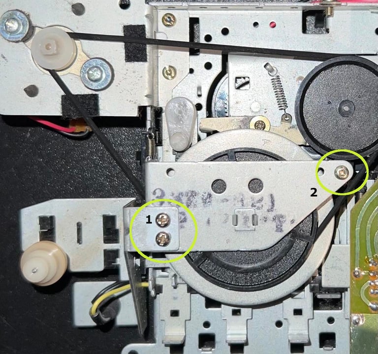
Replacing the motor belt is not difficult, but require a bit more effort. First remove the two screws which holds the counter (marked "1" in picture below). Second, partly unscrew (just loosen it) the screw holding the top gear plate (marked "2" in the picture).

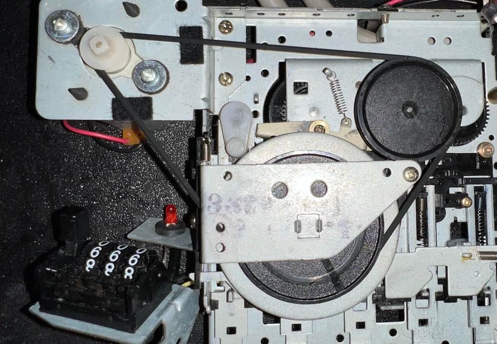
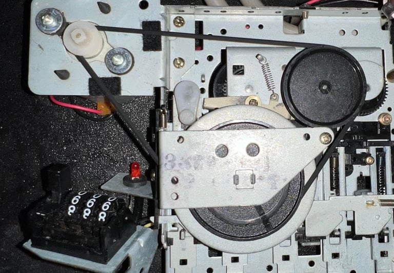
With the counter our of the way a small black plastic bracket is revealed. First I remove the little special screw (marked "3" in the picture below) with a thin flat screwdriver. This screw also have a small spacer so it´s important to note the way it is positioned. Also, note that there is a small pin sticking trough the bracket. This needs to be in aligned when the bracket is replaced (marked "4" in the picture). The plastic bracket doesn´t need to be completely removed - it´s only necessary to loosen it.
Then carefully lift the metal shield on top of the motor flywheel. Also here you don´t need to lift it completely - just lift it enough to get the belt out. There is a small notch in the metal shield where the belt can enter / exit. Picture below show the new belt in place (click to enlarge).
PCB and electrolytic capacitors
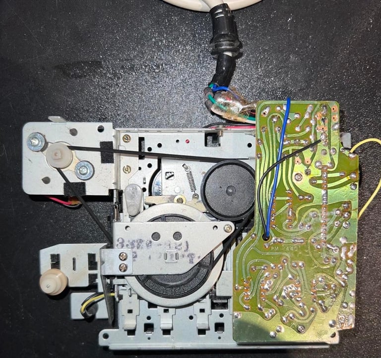
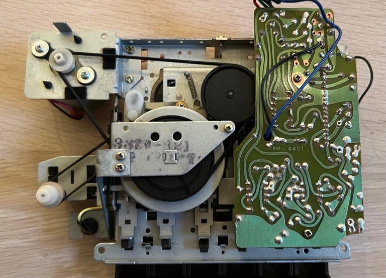
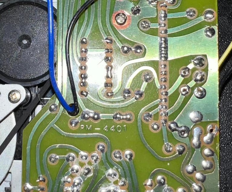
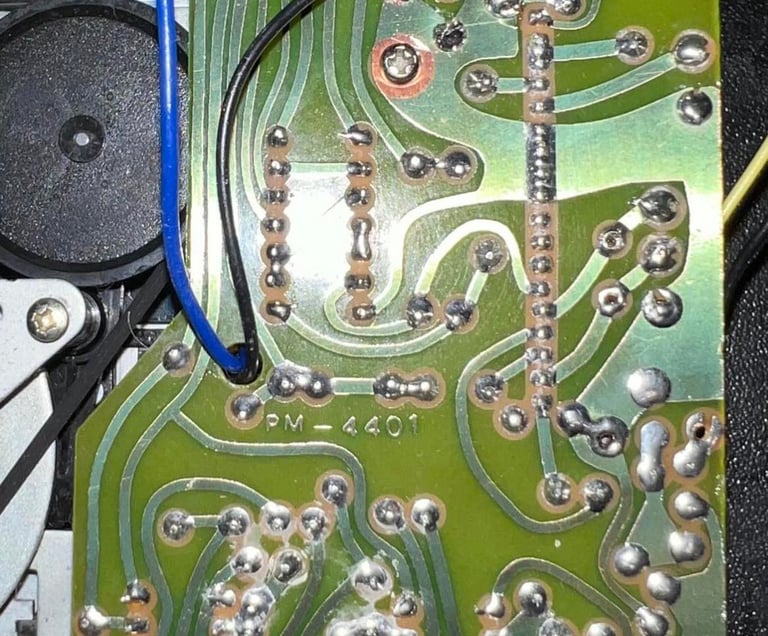
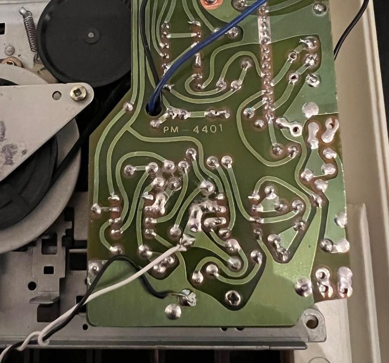
The PCB looks undamaged, but it´s quite "sticky" - due to some kind of residue(?). I clean the PCB with isopropanol and an old tooth brush. The PCB get´s much cleaner - see picture below (click to enlarge).
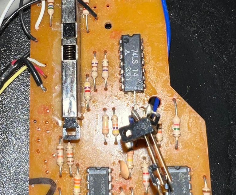
There are two electrolytic capacitors in this datasette: 1 x 220uF [10 V] and 1 x 47uF [10V]. I replace these with new ones since these old capacitors dry up due to old age - which could affect the datasette operation. I use only quality capacitors from Wurth Electronics. Note that the 47uF replacement capacitors is rated for 16 V but that is perfectly fine. Picture below shows the two new capacitors installed (top of picture) - note that the PCB looks a bit wet due to cleaning with isopropanol.

Read/write head alignment
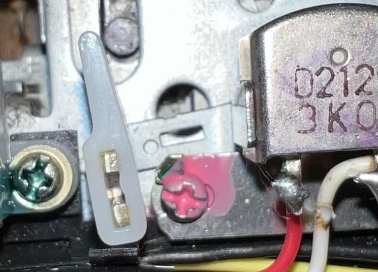
In addition to having new good belts it´s important that the read/write head is aligned for optimal playback. This is done by adjusting the screw positioned left to the R/W head. See picture below (yellow circle).

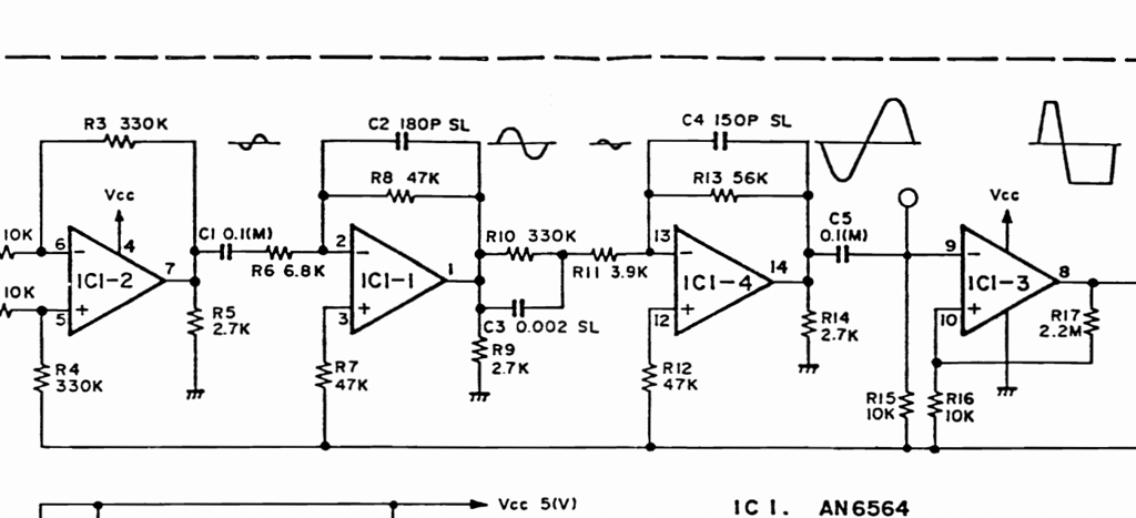
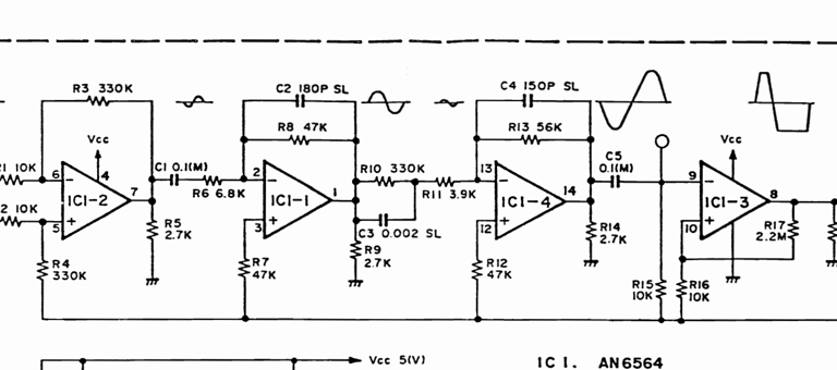
The goal is to adjust this screw until maximum signal amplitude is reached. I don´t have the schematics for this type of datasette, but I use my knowledge on how the signal is amplified from the R/W head to the output signal which is sent to the C64. This datasette (as Commodore 1530 C2N) use four OP-AMP stages in chain to amplify the signal. The signal at the 2nd stage is in my opinion the best position to measure the signal - it´s amplified which is good to make sure we´ve reached optimal alignment, but it´s before the signal amplification saturates and "cuts" the signal in order to make it a square pulse signal. The schematics below is not from this datasette (it is from a 1530 datasette), but it use the same principle with four OP-AMPs in chain. Note how the signal looks normal from the two first OP-AMP stages, but from the 3rd and 4th the signal is saturated and "cut". The schematics is from Service Manual Datasette from Commodore Computers.
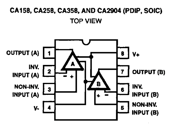
As mentioned I don´t have the schematics for this datasette, but I see that there are two op-amps of the type CA358A. A quick search on the web I find the pinout for this OP-AMP (at DigiKey).

By using the oscilloscope while a tape is running in the datasette I check pin 1 and 7 on the two OP-AMPs and I find the correct position (2nd stage). Then I solder on two wires; one from pin 7 and one from ground. This cable is then made available to the scope probes by the factory made holes at the back of the bottom cover. See picture below for these two positions where the cables are soldered.
Now, with the two wires in place I start to seek out the optimal R/W head alignment. I do this by:
Tightening the screw completely. This is now the starting point of the adjustment.
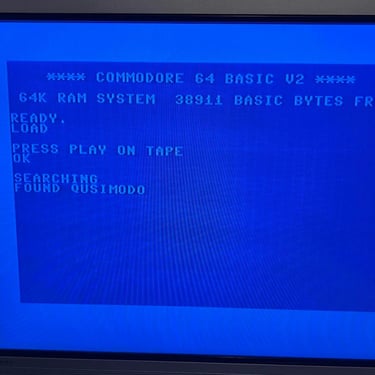
I start playback from an original C64 game tape.
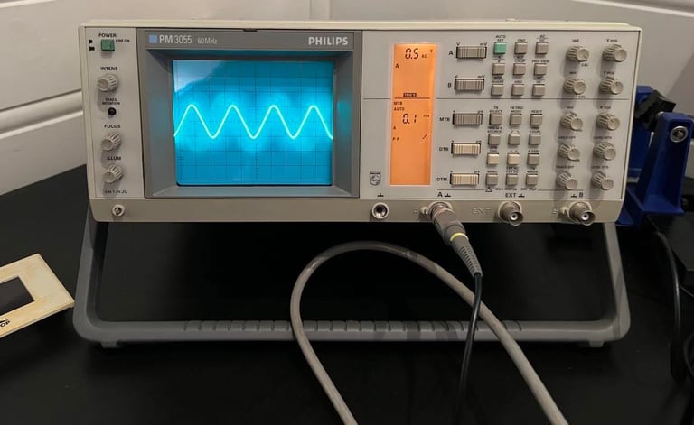
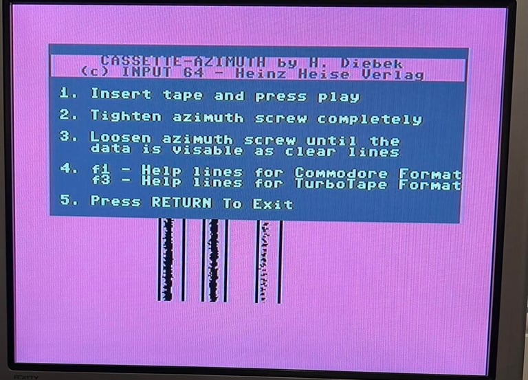
When the signal appear on the oscilloscope I start to carefully adjust the screw - until I find the maximum signal
After I´ve found the optimal position with the oscilloscope I use the Cassette-azimuth software on the C64 to verify the result. This will be confirmed when three signals appear as "solid" lines in the software. And the result on this adjustment is that is does! Mission accomplished!
As a last thing to do I "lock" the screw in position by applying some nail polish on the screw. Note; this is high quality nail polish from Chanel borrowed from my daughter:-)!
Below are some pictures from the alignment process.
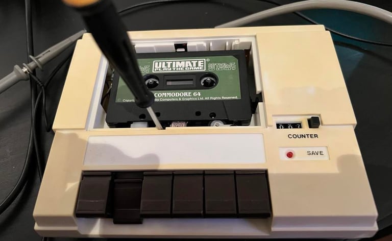
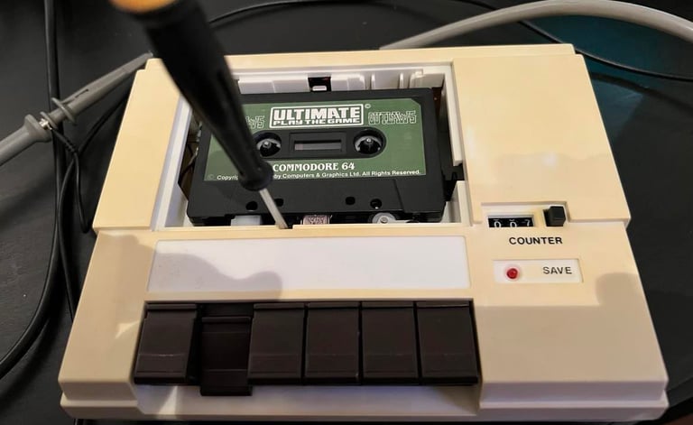

Adjusting the screw during playback.
Using the oscilloscope to find the maximum signal amplitude.
Verification that the maximum signal is reach by checking the cassette-azimuth software tool.
Locking the screw in position with a drop of nail polish.
Testing
It´s time to check that the datasette works as it should. The way I do this is that I pick at random three old original tapes. I know that these works, but they are old and marginal. If they load then that tells me that the datasette can load games as expected. The games I choose are:
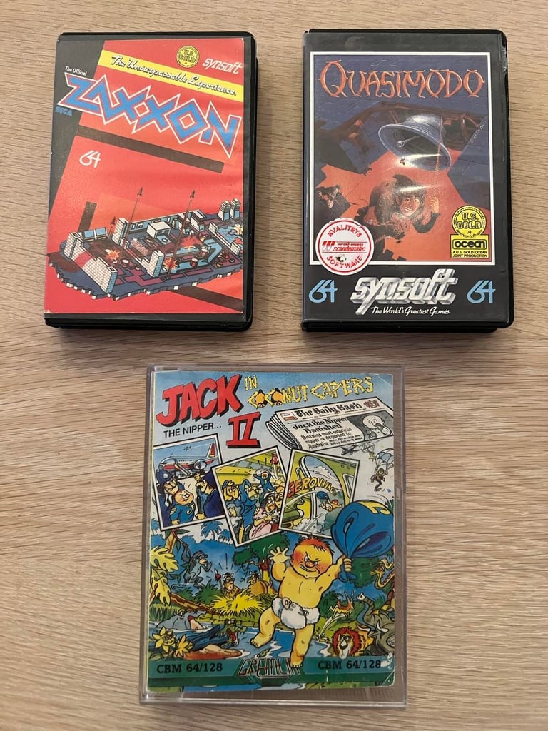
All games loads without any problems or issues. I notice that the eject mechanism works, but when tapes are loaded you need to help the top lid a bit in order for the lid to open. Without any tape the lid pop up without any issue. The spring is maybe a bit worn, but I don´t think this is a problem at all. Also, the SAVE mechanism is also verified to work (note that in order to start recording both the REC and PLAY needs to be pressed down.
Wonder about the PAUSE key? Works fine! Nevertheless, I would recommend to use this gently so that the key don´t break again (but how often do you use a PAUSE key on a C64 datasette? They are not even available on an original Commodore datasette).
Below are some pictures from the testing.

Final result
"A picture worth a thousand words"
Below is a collection of the final result from the refurbishment of this datasette. Hope you like it! Click to enlarge!

