

"No name"
Joystick
Starting point
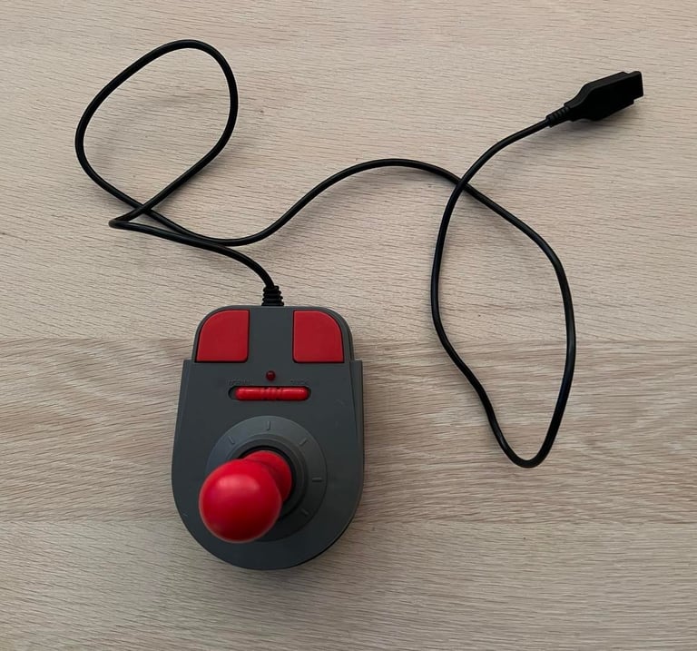
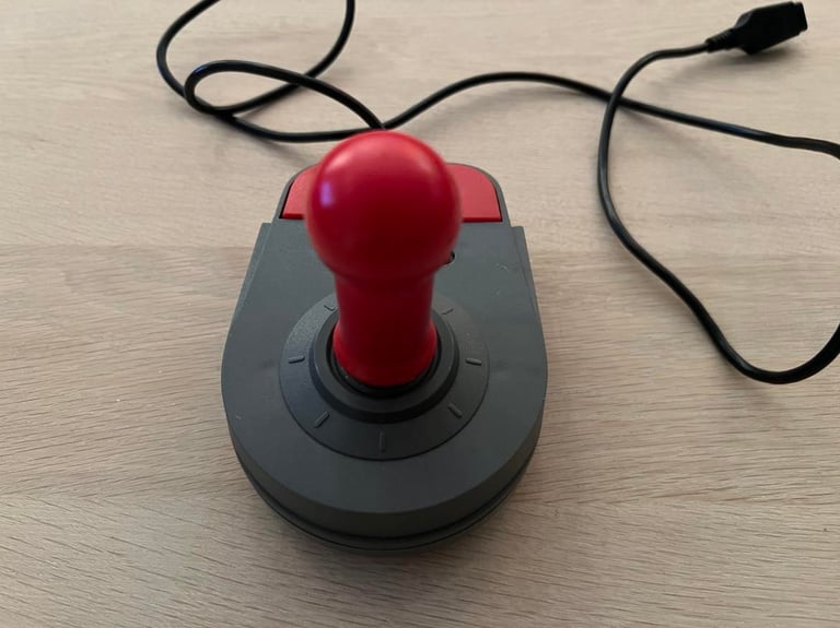
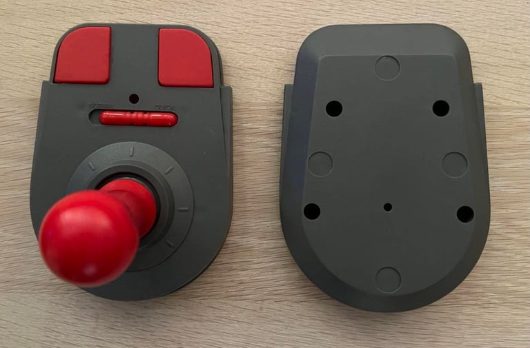
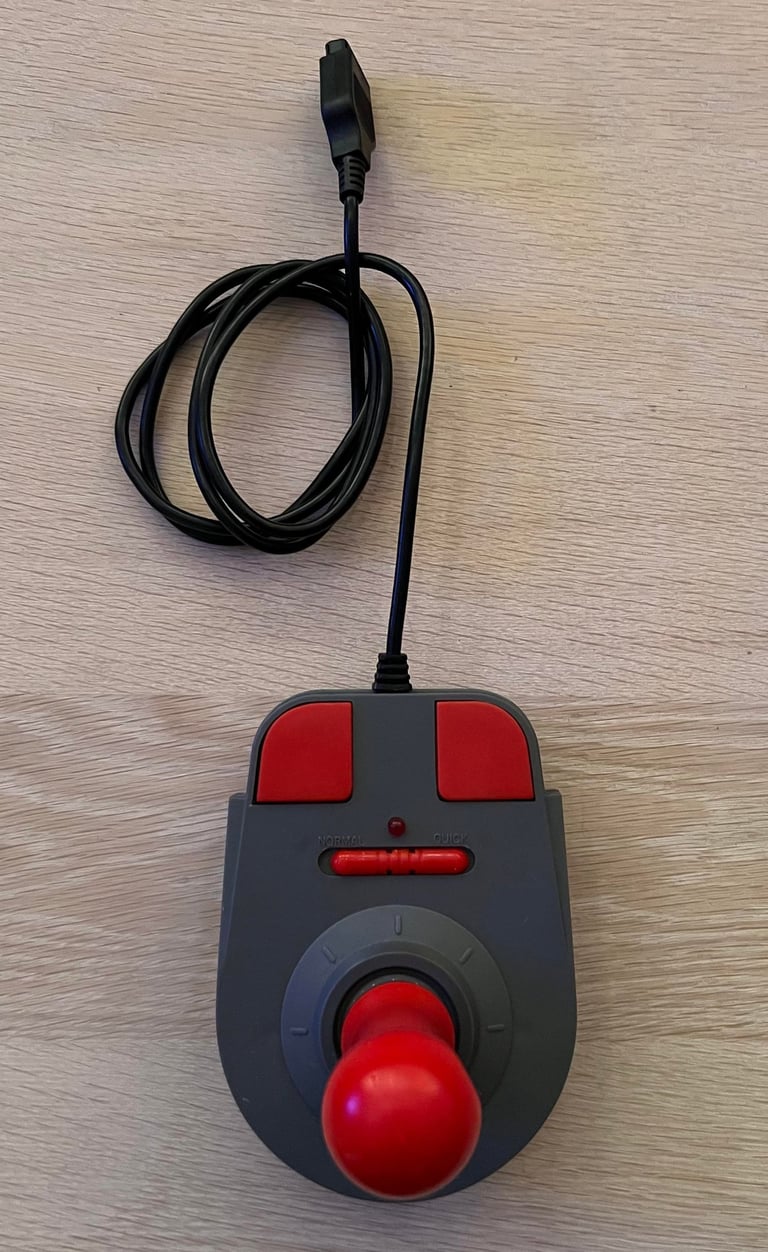
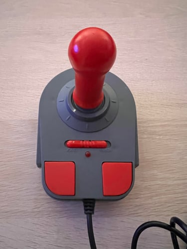
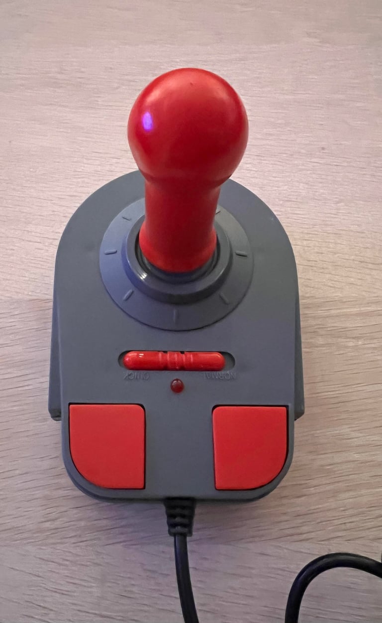
This joystick model is new to me. I´ve never seen this type before. It looks a bit like the famous Powerplay Cruiser, but there are no logo or any information about brand, serial number or origin. Also, I don´t know if this joystick works at all for Commodore/Atari systems. It has the usual 9 pin d-sub connector, but I don´t (yet) know if the wiring is the same - we´ll figure it out!
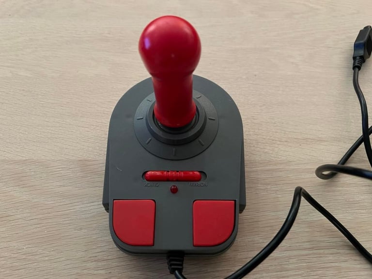
The joystick looks already quite good! Not very dirty and not any visual damage. Also, the buttons and LEFT/RIGHT/UP/DOWN movement are triggered by real "clicks" - almost like microswitches in high quality joysticks. In the center of the joystick is a switch with "Normal/Quick" labels. Some kind of autofire? And above the switch is a LED.
This is probably not a "high quality" joystick, but it feels quite good! Strange that there are no brands or anything...
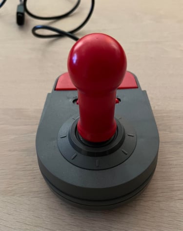
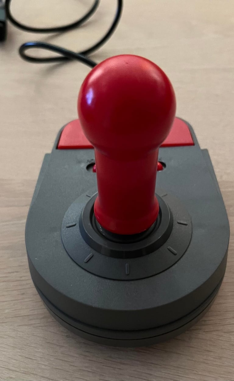
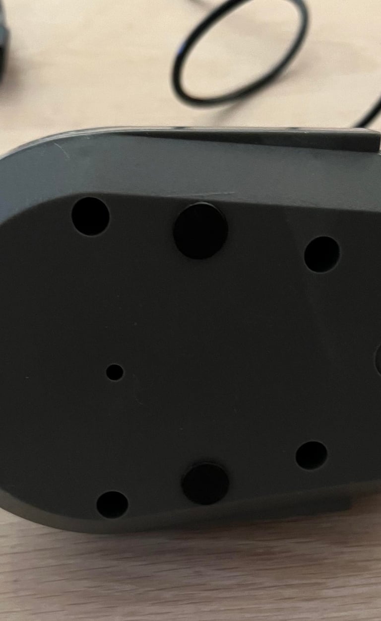
Below are some pictures of the joystick before the refurbishment.

Refurbishment plan
To refurbish this joystick the plan is to do that through the following steps (some of them in parallell):
Clean the exterior chassis
Check and clean interior electronics - and verify that the joystick is Commodore/Atari compliant
Check cable connectivity - replace cable if broken
Verify operation by testing
Exterior chassis
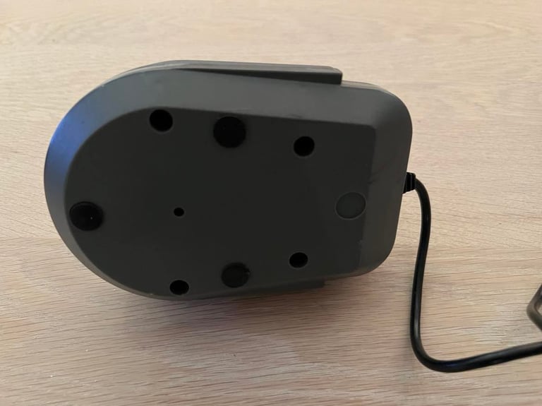
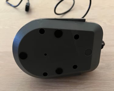
The exterior chassis consists of a top- and bottom cover. To disassemble these four screws at the bottom are removed. Also, the three rubber feets are removed so that they are not damaged during cleaning. Cleaning is done by washing the plastic parts using mild luke warm soap water first. Afterwards the parts are cleaned further with isopropanol and glass cleaning spray. The parts were already quite clean from the start, but below are some pictures after the cleaning.

Interior electronics
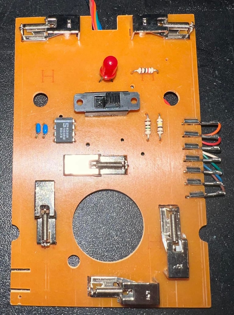
There are no sign of any major corrosion, or other damage, to the PCB when the joystick is opened. That could indicate that the joystick has been stored in a dry place, and also would give hope that the cable is also free from corrosion.
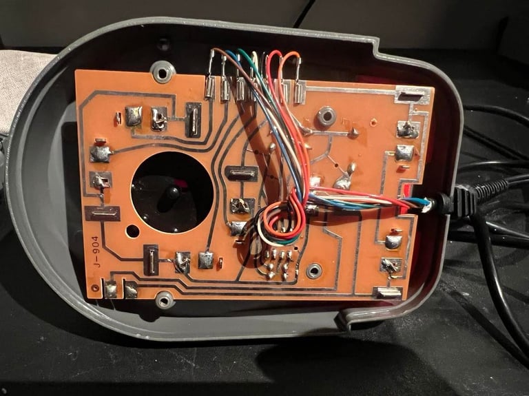
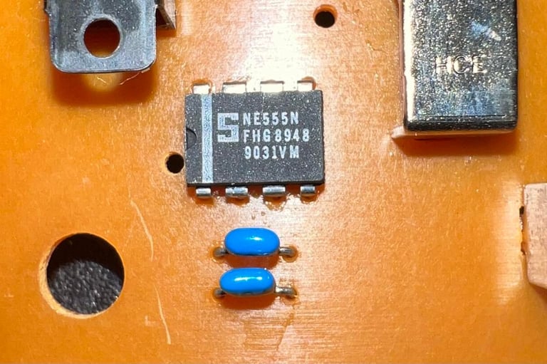
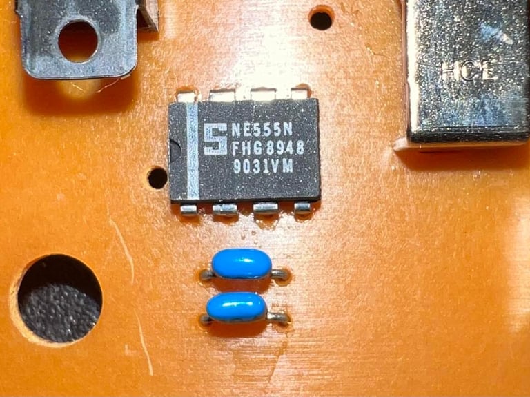
When the PCB is out from the chassis a NE555N chip is revealed. I guess the question of the "Quick" mode is solved; the 555 chip is normally used for timers so this must be an autofire mode. By using a couple of resistors and capacitors it´s straightforward to make a astable oscillator: https://en.wikipedia.org/wiki/555_timer_IC#Examples
Both the back- and front of the PCB are cleaned thoroughly with isopropanol.

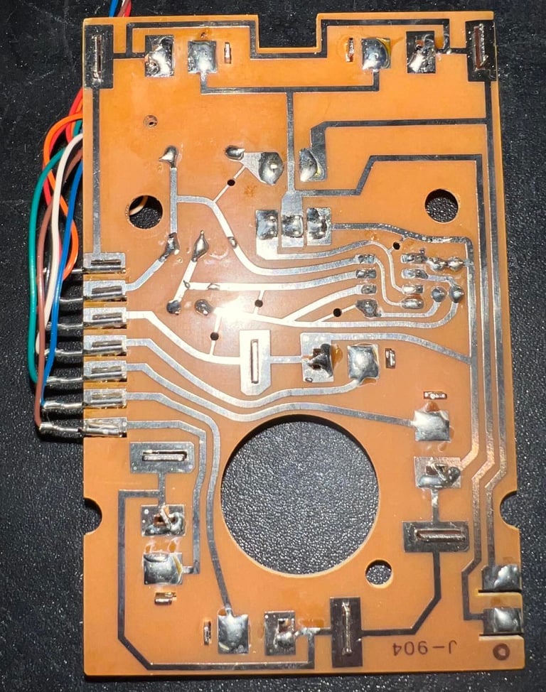
It´s time to investigate if this is in fact an Commodore/Atari joystick. There are seven wires connected to the PCB. My guess is that is UP/DOWN/LEFT/RIGHT/FIRE/+5V/GND. The reason for using the +5V would be to power the 555 chip. The pinout for a Commodore (and Atari for that sake) should be like this (seen from the controller port on the C64):

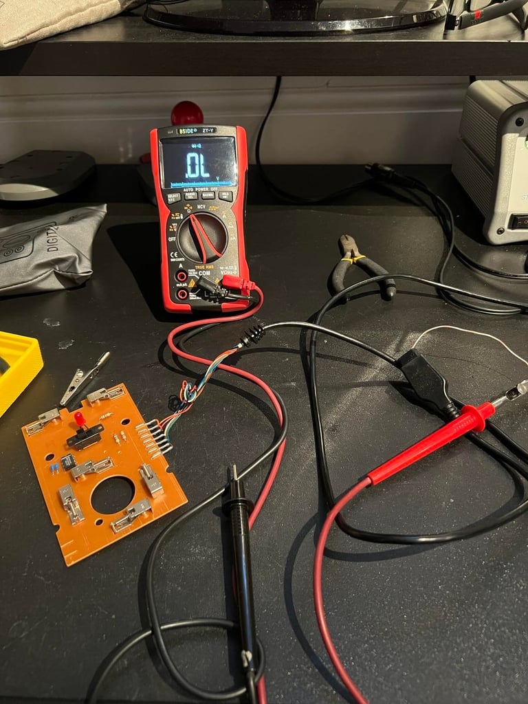
It turns out that all the wires are connected to the "correct" pins at the cable end. That is good! And also that all the wires are working fine - no broken connection.
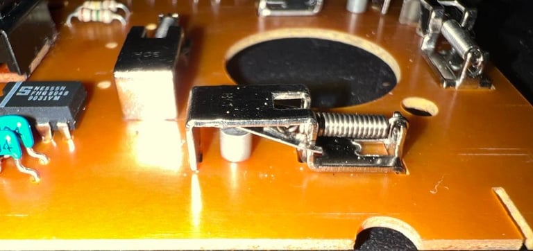
All switches are branded "HCE" and appears to be of quite good quality. I´ve never seen these kind of switches, but they remind me of microswitches except that these are not in a container. The picture below shows one of these six switches (all equal). Note that all switches are cleaned thoroughly with contact cleaner.

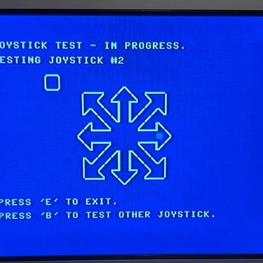
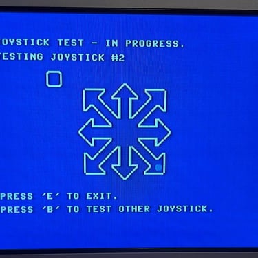
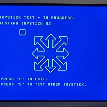
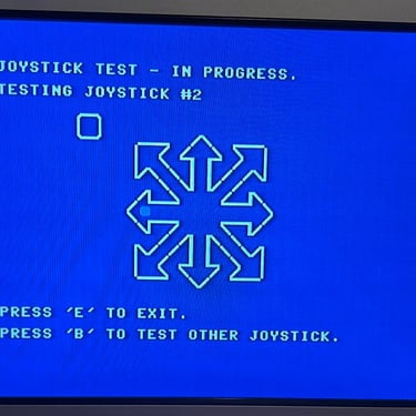
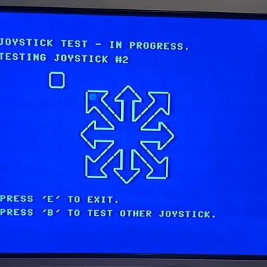
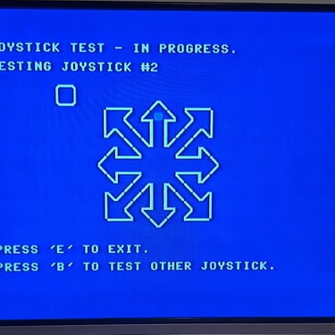
Testing
To verify that the joystick work as it should I check it with the 64 Doctor software. Result is that all directions works fine, and also that fire - and autofire - works as expected. All tests passed.
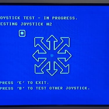
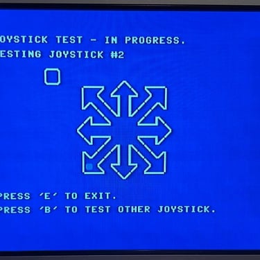
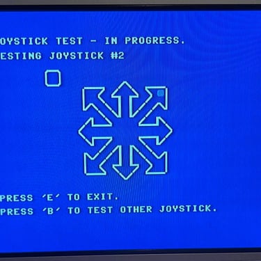
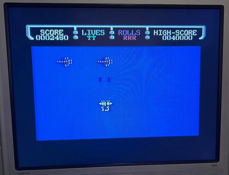
The autofire also works - it´s not so easy to show this with a single picture, but you can find a small video from the testing here. And after the formal testing it´s time to play some games! Who doesn´t love 1942!?

"A picture worth a thousand words"
Below is a collection of the final result from the refurbishment of this joystick. Hope you like it! Click to enlarge!
Final result

Banner picture credits: BHSPitMonkey